

Page 1
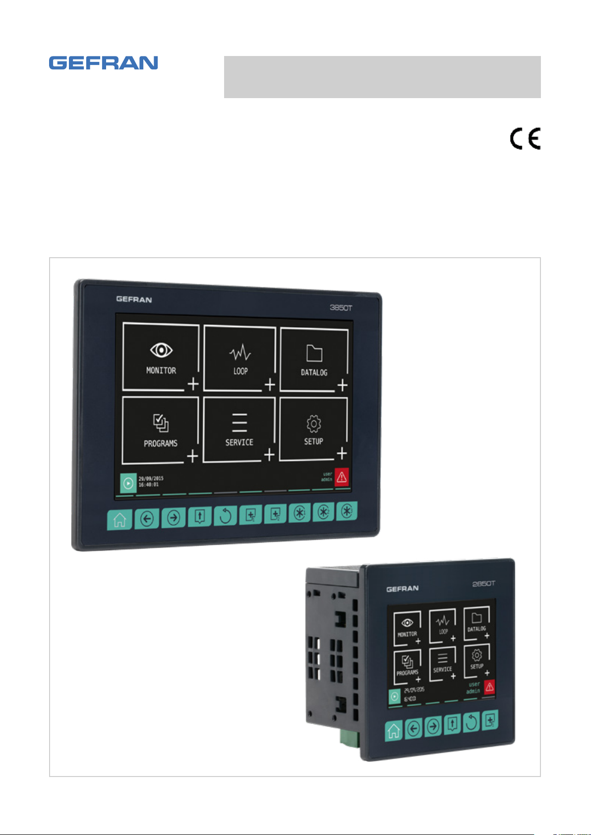
2850T - 3850T
Multi-purpose controller
USE AND INSTALLATION MANUAL
code: 80703B
80703B_MHW_2850T/3850T_02-2019_ENG
Page 2

Page 3

TABLE OF CONTENTS
TABLE OF CONTENTS
Table of Contents ..................................................... 1
Preface ...................................................................... 5
Device data ......................................................................................5
Warnings and safety .........................................................................5
Typical concepts used in the manual ............................................... 6
Glossary ...........................................................................................6
Disclaimer ......................................................................................... 7
Copyright .......................................................................................... 7
1. General Description ......................................... 9
1.1. Profile .....................................................................................9
1.2. Model differences .................................................................10
1.3. Hardware architecture ..........................................................11
1.4. 2850T controller ...................................................................12
1.4.1. Display and keys ........................................................ 12
1.4.2. Dimensions and drilling templates ............................. 13
1.5. 3850T controller ...................................................................14
1.5.1. Display and keys ........................................................ 14
1.5.2. Dimensions and drilling templates ............................. 15
1.6. I/O modules .......................................................................... 16
1.6.1. Compositions ............................................................. 16
1.6.2. Dimensions ................................................................17
2. Installation ......................................................19
2.1. Controller assembly .............................................................19
2.1.1. General installation rules ............................................ 19
2.1.2. Drilling Dimensions ....................................................19
2.1.3. Protection against dust and water infiltration ............ 19
2.1.4. Vibration .....................................................................20
2.1.5. Minimum clearances for ventilation ........................... 20
2.1.6. Positioning .................................................................20
2.1.7. Panel Mount ............................................................... 20
2.2. Installing I/O modules and Gefran communication .............. 21
2.2.1. General installation rules ............................................ 21
2.2.2. Vibration .....................................................................21
2.2.3. Minimum clearances for ventilation ........................... 21
2.2.4. Positioning .................................................................21
2.2.5. Module installation ..................................................... 21
2.3. Connections ......................................................................... 22
2.3.1. General rules for connections .................................... 22
2.3.2. Electromagnetic Compatibility (EMC) ........................ 22
2.3.3. Cables ........................................................................ 22
2.3.4. Voltage .......................................................................22
2.2.6. Removing Modules .................................................... 22
2.3.5. Input and output connections .................................... 23
2.4. Interface connection diagram ..............................................23
2.5. Ethernet Connections ..........................................................23
2.5.1. Private networks and public networks ....................... 24
2.5.2. Firewall .......................................................................24
2.5.3. Router ........................................................................24
2.5.4. VNC (Virtual Network Computing)..............................24
2.5.5. VNC Server ................................................................24
2.5.6. VNC Viewer ................................................................ 25
2.6. F-GCANs communication module connection diagram ...... 25
2.7. F-MIX module connection diagrams .................................... 26
2.7.1. General layout ............................................................ 26
2.7.2. Voltage .......................................................................27
2.7.3. Digital inputs .............................................................. 27
2.7.4. Analog inputs ............................................................. 27
2.7.5. Digital outputs ............................................................ 29
2.7.6. Analog outputs ........................................................... 29
2.8. F-EU16 digital I/O module connection diagram ................... 29
2.9. Touch Screen calibration procedure ....................................30
3. Commissioning ............................................... 33
3.1. Display information and key use .......................................... 33
3.1.1. Navigation .................................................................. 33
3.1.2. Virtual keyboards .......................................................33
3.2. Behavior when turned on ..................................................... 33
3.3. First start-up ......................................................................... 34
4. Menu and Configuration ................................ 35
4.1. Login password ....................................................................35
4.2. Display, configuration and management ..............................35
4.3. Monitor Program ..................................................................36
4.4. Monitor Recorder .................................................................37
4.5. Main menu (controller with all options) ................................38
4.6. Controller menu with programmer, GETLogic, GETview and
recorder ................................................................................39
4.7. Controller menu with GETLogic and GETview options ........40
4.8. Tool menu with GETLogic, GETview and recorder options .41
4.9. Controller menu with GETLogic, GETview and recorder
options ................................................................................42
4.10. MONITOR menu ................................................................... 43
4.10.1. STATUS sub-menu .....................................................43
4.10.2. ALARM HISTORY sub-menu .....................................43
4.10.3. MONITOR PROGR sub-menu ...................................43
4.10.4. GETview sub-menu ....................................................44
4.10.5. INFO sub-menu .........................................................44
4.10.6. ENERGY sub-menu ...................................................44
4.11. LOOP Menu .........................................................................46
4.11.1. Editing parameters ..................................................... 46
4.12. DATALOG Menu ...................................................................47
4.12.1. The Datalog ................................................................ 47
4.12.1.1. Archive Mode ....................................................47
4.12.1.2. File compression on the local disk ....................47
4.12.1.3. Amount of savable sampled data ......................47
4.12.1.4. Out of memory alarms .......................................47
4.12.2. TREND sub-menu ...................................................... 48
4.12.2.1. Graph Scale .......................................................48
4.12.2.2. Trend configuration ...........................................48
4.12.3. EXPORT sub-menu .................................................... 49
4.12.3.1. File format and data structure ...........................49
4.12.4. TREND HISTORY sub-menu ...................................... 50
4.13. PROGRAMS Menu ............................................................... 51
4.13.1. What is a Program .....................................................51
4.13.2. Loading and selecting the program ........................... 51
4.13.3. Configuring the program ............................................ 52
4.13.3.1. Base program configuration ..............................52
4.13.3.2. Configuring the Program Segments ..................54
4.13.3.3. GETlogic configuration ......................................56
4.13.3.4. Program report configuration ............................69
4.13.4. Read from disk sub-menu .........................................69
4.13.5. New prog sub-menu .................................................. 69
4.14. SERVICE Menu ....................................................................71
4.14.1. LANGUAGE sub-menu ..............................................71
4.14.2. SETUP sub-menu ......................................................71
4.14.2.1. Configuration Section ........................................71
4.14.2.2. Network Configuration ......................................72
4.14.2.3. Network NTP and VNC Configuration ...............72
4.14.2.4. Display Configuration ........................................72
4.14.2.5. Information Section ...........................................73
4.14.2.6. Fieldbus Information ..........................................73
4.14.2.7. CANopen Information ........................................73
4.14.2.8. Modbus TCP Information ..................................73
80703B_MHW_2850T/3850T_02-2019_ENG 1
Page 4

TABLE OF CONTENTS
4.14.2.9. Temperature Information ...................................74
4.14.2.10. Information System Message ............................74
4.14.3. DATA TIME sub-menu ................................................74
4.14.4. PROGRAM CLOCK sub-menu ..................................75
4.14.5. PROGRAMS MGR sub-menu .................................... 75
4.15. SETUP Menu ........................................................................ 76
4.15.1. HW CFG sub-menu....................................................76
4.15.1.1. I/O terminal exchange .......................................76
4.15.1.2. F-MIX analog input configuration ......................77
4.15.1.3. F-MIX analog output configuration ....................78
4.15.1.4. F-MIX digital input configuration .......................78
4.15.1.5. F-MIX digital output configuration .....................78
4.15.1.6. F-EU16 digital input configuration .....................79
4.15.1.7. F-EU16 digital output configuration ..................79
4.15.2. ALARM CFG sub-menu ............................................. 80
4.15.3. SETUP MGR sub-menu ............................................. 80
4.15.3.1. “Controller model” SETUP ................................80
4.15.3.2. SETUP MGR ......................................................81
4.15.3.3. IMAGE ...............................................................82
4.15.3.4. “Controller model” RESET ................................82
4.15.4. PID CFG sub-menu ....................................................82
4.15.4.1. PID configuration procedure .............................82
4.15.4.2. PID base configuration ......................................83
4.15.4.3. PID advanced configuration ..............................83
4.15.4.4. PID limit configuration .......................................84
4.15.4.5. Configuration of PID Gradient ...........................85
4.15.4.6. PID valve configuration ......................................85
4.15.4.7. PID alarm configuration .....................................85
4.15.4.8. PID HB alarm configuration ...............................86
4.15.4.9. PID variable configuration .................................87
4.15.4.10. PID synoptic configuration ................................89
4.15.5. VAR CFG sub-menu ...................................................90
4.15.6. USER CFG sub-menu ................................................ 90
5. Custom pages ................................................91
5.1. Examples of custom pages .................................................. 91
5.1.1. Example of Pit Kiln ..................................................... 91
5.1.2. Example of a Food Steriliser ...................................... 91
5.1.3. Example of Kiln heat processing ...............................91
5.2. Go to the menu page ...........................................................92
5.3. Creating a custom page .......................................................92
5.3.1. Screen coordinates .................................................... 92
5.3.2. Creating and editing a component ............................92
5.1.4. Example of autoclave .................................................92
5.3.2.1. Precision component configuration ..................93
5.3.2.2. Color ..................................................................93
5.3.2.3. Overlapping components ..................................93
5.3.3. LED Component ........................................................93
5.3.4. Edit Text component .................................................. 93
5.3.5. Text component ......................................................... 94
5.3.6. Note component ........................................................ 94
5.3.7. Progress Bar component ........................................... 94
5.3.8. Data View component ................................................ 95
5.3.9. Data Set component .................................................. 95
5.3.10. Button component ..................................................... 95
5.3.11. Image component ...................................................... 96
5.3.12. Change page component .......................................... 96
5.4. Custom page creation tutorial ..............................................97
5.4.1. Page Creation Procedure ...........................................97
5.4.2. Adding Bar Graphs ....................................................98
5.4.3. Adding Data View .......................................................98
5.4.4. Adding a Data Set ...................................................... 99
5.4.5. Adding LEDs .............................................................. 99
5.4.6. Adding Text ................................................................ 99
5.4.7. Adding an image ...................................................... 101
6. SERVICE PAGES ...........................................103
6.1. Variable selections .............................................................103
6.2. Active alarm .......................................................................103
7. Examples and application notes .................105
7.1. Multi kiln control .................................................................105
7.1.1. Managing parameter groups ....................................105
7.1.2. Configuration Procedure .......................................... 105
7.2. Building programs with default segments (TEMPLATE) ..... 106
7.2.1. Program composition with TEMPLATES..................106
7.2.2. Configuration Procedure .......................................... 106
7.3. Correction of linear inputs and outputs..............................107
7.3.1. Calibration of input ...................................................107
7.3.2. Correction of input ................................................... 107
7.3.3. Correction of output ................................................. 107
7.4. Alarms ................................................................................108
7.4.1. Generic alarms ......................................................... 108
7.5. Control ................................................................................109
7.5.1. Control actions ......................................................... 109
7.5.1.1. Proportional, Derivative and Integral action influ-
ence on the controlled process feedback .......109
7.5.2. Self-Tuning ............................................................... 109
7.5.3. Cascade control ....................................................... 109
7.5.3.1. Tuning two PIDs configured for cascade control ..
110
7.5.4. Ratio control ............................................................. 110
7.6. Motorised valve control ......................................................111
7.6.1. Valve control parameters .........................................111
7.6.2. Valve control mode ..................................................111
7.7. Practical configuration examples ....................................... 113
7.7.1. Loop configuration ................................................... 113
7.7.2. Configuring a LOOP controller with input equal to the
average value of 3 variables ....................................115
7.7.3. 2-curve setpoint profile ............................................ 119
8. Maintenance .................................................123
8.1. Gasket replacement ...........................................................123
8.2. Configuration cloning ......................................................... 123
8.3. Cleaning .............................................................................123
8.4. Disposal .............................................................................123
8.5. Troubleshooting ..................................................................124
8.5.1. LED signals .............................................................. 124
8.5.2. System signals ......................................................... 125
9. 2850T-3850T configuration in GF_eXpress .....
127
9.1. Target Selection .................................................................. 127
9.2. Offline Target Configuration ...............................................128
9.3. Online Target Configuration ................................................ 129
9.3.1. HW and functional options of the target aligned with
those of the configurator ..........................................129
9.3.2. HW and functional options of the target not aligned
with those of the configurator .................................. 130
9.4. Making changes to the configurator ..................................131
9.4.1. “PROGRAMMER EDITOR” section..........................132
9.4.1.1. “GETLogic” section ........................................132
9.4.1.2. “GRAPHICS” section ......................................133
9.4.2. “LOOP” section ........................................................134
9.4.3. “GETview” section ................................................... 134
9.4.3.1. MANAGEMENT OF GRAPHIC COMPONENTS ...
134
9.4.4. “USERS” section......................................................135
9.4.5. “CFG HARDWARE” section ..................................... 136
9.4.6. “SETUP” section ...................................................... 136
9.4.7. “ENERGY” section ................................................... 137
9.4.8. “VARIABLES” section ..............................................137
9.4.9. “PARAMETERS” section ..........................................138
80703B_MHW_2850T/3850T_02-2019_ENG2
Page 5

10. Technical specifications ..............................139
10.1. 2850T controller ................................................................. 139
10.2. 3850T controller ................................................................. 144
10.3. F-GCANs communications module ................................... 149
10.4. F-MIX module ..................................................................... 150
10.5. F-EU16 module .................................................................. 153
11. Order codes ..................................................155
11.1. 2850T controller ................................................................. 155
11.2. 3850T controller ................................................................. 157
12. Accessories ..................................................159
13. ANNEXES ......................................................161
13.1. System variables ................................................................ 161
13.1.1. General ..................................................................... 161
13.1.2. PID loop ...................................................................161
13.1.3. SP Programmer........................................................161
13.1.6. Alarms ...................................................................... 163
13.1.5. Weekly clock ............................................................163
13.1.4. Energy ......................................................................163
13.2. ImageConverter DELETE CHAPTER 12.2 .......................... 164
13.2.1. What an ImageConverter is .....................................164
13.2.2. ImageConverter installation ..................................... 164
13.2.3. Converting an image to .plk format .........................165
TABLE OF CONTENTS
80703B_MHW_2850T/3850T_02-2019_ENG 3
Page 6

80703B_MHW_2850T/3850T_02-2019_ENG4
Page 7
PREFACE
PREFACE
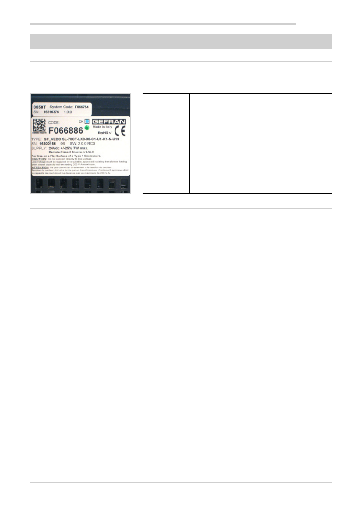
Device data
Write the order code and other plate data found on the label applied to the controller exterior here (see illustration). Should
you need technical assistance, they must be communicated to Gefran Customer Service.
Serial number SN
Finished product
code
Order code TYPE
Power voltage SUPPLY
Firmware version VERS.
Warnings and safety
The devices illustrated in the manual must be installed by
qualified technicians, following the laws and regulations in
effect and according to the instructions contained in this
manual.
Installation and/or maintenance technicians must read
this manual and strictly follow the instructions herein and
found in the annexes since Gefran cannot be held liable
for personal, property and/or product damages should the
following conditions not be met.
CODE
This manual must be available to people who interact with
the devices described herein.
Before interacting with 2850T and 3850T multi-purpose
controllers, the operator must be adequately instructed on
the device operating, emergency, diagnostics and maintenance procedures.
If 2850T and 3850T multi-purpose controllers are used in
applications with risk of personal, machine or material damages, they must be combined with auxiliary alarm devices.
We recommend ensuring the ability to check alarm operations even during normal operations.
Do not touch live device terminals.
Before contacting Gefran Customer Service, in the event of
alleged instrument malfunctions, we recommend consulting
the Troubleshooting Guide in the "Maintenance"
80703B_MHW_2850T/3850T_02-2019_ENG 5
Page 8

PREFACE
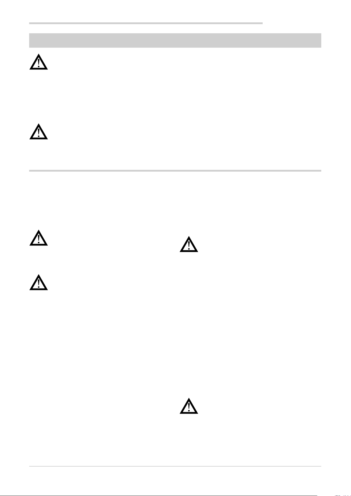
Typical concepts used in the manual
Pay attention when the following symbols are found in the manual.
They indicate particularly important information
that effect correct product operations or safety, or
provide mandatory instructions.
They indicate a risk condition for the installation
technician or user due to hazardous voltages.
They call the reader's attention to a specific point.
Glossary
They signal a suggestion that could be helpful for
better device use.
4...20 mA Electrical current used as a signal that is
transmitted by certain sensors or that is
specifically used to control a device such
as, for example, a motor-driven valve.
Alarm Output that is triggered when a certain
condition is met such as, for example, a
certain temperature.
Auto Tune Function that lets you easily calculate and
set P, I and D parameters thanks to controller self-learning.
Batch Production batch ID.
Batch Report A series of analog and digital variables are
generally associated with the batch. The
report starts with the program RUN command and ends when the program END
status is reached.
Blocks Default controls for specifications
Function function used in Sequential Logics.
Cool Control used for cooling.
Data log
encryption Technology that guaranteed logged data
integrity (DataLog and Batch).
The saved file is read and write protected
by a CRC control. Encrypted files can be
decrypted by the DataLog Utility for PC.
Datalogger Continuous recording function for a series
of analog and digital variables.
GETLogic Gefran Embedded Technology: function
that lets you set Sequential Logics directly
from the terminal.
GETView Gefran Embedded Technology: function
that lets you set custom graphics pages
directly from the terminal.
HBB Alarm Hold Back Band: alarm associated
with the SP profile, that checks that the
reference variable (PV) remains within a
tolerance band set according to the generated SP. If PV goes outside the set band,
the profile generator will be shut down and
HBB WAIT will appear on the monitor. The
profile generator automatically returns to
RUN when PV returns within the tolerance
band. If you want to move forward with
profile steps in HBB condition, SKIP is
permitted, provided you first go to HOLD
STATUS.
HB Heater Break Alarm: requires use of cur-
rent transformer inputs, associated with a
control output, of which it takes into consideration the ON and OFF phases. The
alarm signals changes in load absorption,
discriminating between current values for
current inputs.
Heat/Cool Control that is used both for heating and
cooling (requires two control outputs).
Heat Control used for heating.
Hysteresis When the value of the controlled variable,
at a precise moment, depends not only
from another reference variable, but also
by the values which the controlled variable
had previously, we are in the presence of
hysteresis. The hysteresis can therefore be
seen as an inertia which affects the control
system, causing variable delays between
variation of the reference variable and
variation of the controlled variable.
Sequential Logic
ON-OFF Control procedure based on output on and
Overshoot Situation where PV exceeds SP because
PID Acronym for Proportional-Integration-Dif-
Sequence of function blocks that describe
the sequential management of the machine cycle.
off. In heating control, the output remains
active until PV is a certain amount less
than SV (offset), and then turns off until
PV is higher than SV by the same amount
(or different, depending on the controller
configuration). In the case of cooling, the
output it is on until PV > SV - offset and off
until PV < SV + offset. This type of control
is not intelligent, does not take account of
the disturbances and is not very accurate,
but ensures a limited number of output
switching.
the control action was too late. The ONOFF controls have a greater overshoot
than the PID controls.
ferentiation indicates a negative feedback
80703B_MHW_2850T/3850T_02-2019_ENG6
Page 9

PREFACE
system, meaning a device whose input
acquires a value from a process, compares
it with a reference value and uses the
difference (error) for determine the value
of the controller output variable, which is
the variable that controls the process itself.
The output is controlled according to the
actual error value (proportional action), a
set of previous error values (integral action)
and the error value rate of change (derivative action).
Setpoint Profile
Program
Pt100 Commonly used temperature probe.
PV Acronym for Process Value, which is the
Solid State
Relay Also known as SSR (Solid-state relay) is
a relay designed specially for frequent
switching. There are no moving parts
or mechanical contacts, but may, however,
fail or short circuit. These types of relays
are often used in temperature control
systems such as PID.
Segment Basic element for the configuration of a
See SP.
Function set (Sp Profile, Sequential Logic,
Recording) that describe a production cycle.
At 0° C /F, its resistance is 100 ohms, while
at room temperature is about 106 ohms.
You can test the Pt100 for electrical continuity and you can use normal extension
cords.
value that the process variable (temperature, valve opening, etc.) has at that
moment.
SP profile. It describes the operations of
an individual segment in detail. The set of
segments describes the execution of a SP
profile.
Sensor A device that translates physical phenom-
ena (i.e. resistance variation as a function
of temperature) in electrical signals that
can be acquired and processed by the
controller.
Setpoint Set value (see SV).
SSP SP/FSSPActive set point, in the case of a
set point gradient, shows its real value.
SP Acronym for Setpoint Profile meaning the
set of segments that describe the trend
over time of a value, typically a setpoint
and the status of a series of digital events
(In/Out).
SV Acronym for Set Value which is the value
that the process variable (temperature,
valve opening, etc.) must achieve and
maintain.
TA Current transformer
Thermocouple Sensor that transmits an electrical signal
of a few millivolts, that cannot be tested
for electrical continuity.
It needs specially designed extension
cords.
Undershoot Situation where PV does not reach SV
because the control action was too early.
The ON-OFF controls have an undershoot
greater than the PID controls.
Engineering unit
Control output Output that controls the process and is
Unit of measure suited to directly express
the measured physical variable value.
turned on and off as needed.
Disclaimer
Although all information contained within this document has
been carefully checked, Gefran S.p.A. cannot be held liable
for the possible presence of errors, or damage to persons
or property due to improper use of this manual.
Gefran S.p.A. also reserves the right to make changes
to the content and form of this document as well as the
characteristics of the illustrated devices at any time without
prior notice.
The technical and performance data indicated in this
manual are to be considered as a guide for the user to
determine the suitability for a certain use, and are not
guarantees. They may be the result of Gefran S.p.A. test
conditions and the user must compare them to his/her real
application requirements.
Gefran S.p.A. cannot be held in any way liable for any damage to persons or property resulting from controller tampering, incorrect and improper use or otherwise non compliant
with controller features and instructions in this manual.
Copyright
This document and its annexes may be freely reproduced,
provided that the contents are not modified in any way
and each copy includes this warning and the statement of
Gefran S.p.A. ownership.
80703B_MHW_2850T/3850T_02-2019_ENG 7
Gefran and GF_eXpress are trademarks of Gefran S.p.A.
The document may mention or reproduce trademarks and
logos of third parties. Gefran S.p.A. acknowledges the ownership of these trademarks or logos by their respective owners.
Page 10

80703B_MHW_2850T/3850T_02-2019_ENG8
Page 11
1.1. Profile
1. GENERAL DESCRIPTION
1. GENERAL DESCRIPTION
2850T 3850T
The 2850T and 3850T multi-purpose controllers designed
to control the temperature in production processes (heat
treatment, kiln and autoclave management, etc.) used in
different industrial sectors such as automotive, food, metalworks, etc.
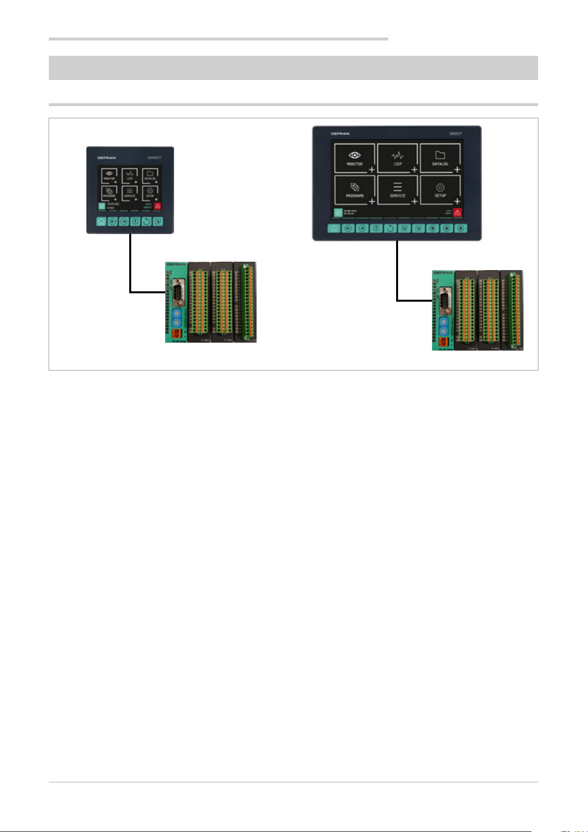
The controllers consist of three elements: the operator interface with touch screen display and keys, the I/O module
group for connection to plants and machinery and the connection cable between the interface and the module group.
The two controllers share the same main features and the
same functions. The differences are listed in paragraph
“1.2. Model differences” on page 10.
The color touch screen display (3.5" for the 2850T model
and 7" for the 3850T model) allows the operator to easily
and quickly interact with the controller, managing actions
and parameters.
Access to the main controller functions and navigation
between pages is made easier thanks to its function keys
(6 for model 2850T and 10 for model 3850T), some of which
are customisable.
Customized pages may be configured directly on the display, even without a PC or external software. This option allows you create optimised graphic interfaces to control the
machinery used. A graphic symbol library is provided for
this purpose (buttons, bargraph, data display, etc.) that can
be set and linked to the controller variables. You may also
import images, such as representations of the machinery or
of the system’s operating diagram, to be used as a background, to make control even more intuitive for operators.
Controllers can control different PID (up to 8 for model
2850T and up to 16 for model 3850T) fully configurable.
Each PID can be used as a control for a single loop, a valve
or a ratio control, it can be connected to the profile pro-
grammer or be used as a cascade controller.
Tuning is performed through advanced algorithms that
ensure stable and accurate temperature control, avoiding
exceeding set limits or having unstable process control
even in critical heat or fast motion processes.
The setpoint profile programmer allows you to set the
programs to manage heat treatment cycles. The profile is
the set of segments that describe the setpoint curve. You
can create up to 200 (model 2850T) or 250 (model 3850T)
programs, stored internally, each of which can contain up to
50 segments.
Each program lets you set up to four setpoint profiles. A descriptive message, 16 input events (IN), 16 outbound events
(OUT), the setpoint value and the HBB alarm threshold can
be set for each program.
You can launch up to four programs simultaneously with
the 2850T model and 8 programs simultaneously with the
3850T model, each of which can handle up to 4 synchronous profiles.
The profile programmer can be set in synchronous mode
(all profiles are run with a common time base) or asynchronous (each profile can be run with an independent time
base). The asynchronous mode is obtained by running
different programs simultaneously.
The available logical operators (AND, OR, Timer, Counter
etc.) allow you to create custom logic operating sequences integrated with , thus obtaining complete and flexible
machine control.
The available settable mathematical functions (addition,
multiplication, division, minimum or maximum value, algorithms, etc.) can be used associated with process values as
analog channels and virtual channels, to manage advanced
controls, such as ratio controls or custom mathematical
formulas.
80703B_MHW_2850T/3850T_02-2019_ENG
9
Page 12

1. GENERAL DESCRIPTION
The Data Logger function, combined with the Real Time
Clock (RTC clock with rechargeable buffer battery) stores
process data, IN/OUT signals and the status of the alarms
in an open file (.CSV format) or encrypted file. The minimum data sampling frequency is 1 second. Saved files can
then be exported from the controller via USB or Ethernet
network.
The batch report option lets you to associate this data
with a specific batch produced, to be able to use them in
production and quality reports.
A specific application for PC (Report Utility) is available for
easy management of all data logger data and the production batch reports which allows you to manually copy and
delete files via an Ethernet network between the controller
and a PC or automatically at dates that can be set manually
by the operator. The data stored on the PC can then be
displayed in graphical format or a spreadsheet (Excel type)
or exported as CSV or PDF files.
For the quick and safe installation of the machinery or plant,
use the recipes stored in the controller. The recipes, easily
retrievable by the operator, can be of two types: OEM
manufacturer recipes, which contain the machine setup
parameters and production recipes, which contain single
production settings (profile program, logical steps, math
functions).
The recipes can be easily transferred between different
controllers via USB key or Ethernet network.
Controllers offer complete diagnostics (probe break down
or incorrect connection, total or partial load break down,
control loop faults), which helps the operator in case of
controlled machine or process faults.
All controller alarms are stored internally and can be
viewed as Active alarms and Historical alarms. The relevant
message is displayed for each historical alarm with the
date and time of the various states (active alarm, ACK, and
alarm cleared). The ACK parameter, settable for each alarm,
ensures that the active alarm was acknowledged by the
operator.
An internal energy counter, with configurable offset alarm,
provides energy consumption and cost totals.
For accurate time stamps, the controller supports the
Simple Network Time Protocol (SNTP) service, which continuously updates the controller's date and time from the
SNTP server connected via Ethernet network.
The weekly clock function lets you automatically start or
stop a programmer or a process, without the need of operator intervention.
The clock is based on a settable weekly calendar (day of
week and time).
The display language selection lets the operator interact
with the device in the preferred language, facilitating work.
Secure access to all controller parameters is guaranteed by
3 preconfigured password levels (Operator, Maintenance
technician and OEM manufacturer). In this way, each user
can only access the assigned functions and parameters.
You can connect the controller to the factory HMI/SCADA
network by using standard Modbus TCP (Ethernet) con-
nectivity.
Complete controller configuration is facilitated by use of the
PC programming tool GF_express, which proposes intuitive
Wizard pages, permitting easy construction of customized
graphic pages and advanced logic.
1.2. Model differences
2850T 3850T
Touch Screen display dimensions 3,5” 7”
Number of keys 6 10
Number of customisable keys 0 3
Max number of LOOP 8 16
Max number of programs 200 250
Logical and mathematical operations 200 200
Data Logger analog values 25 50
Data Logger digital events 50 50
Interface dimensions 100 × 100 mm 198 × 134.4 mm
10
80703B_MHW_2850T/3850T_02-2019_ENG
Page 13
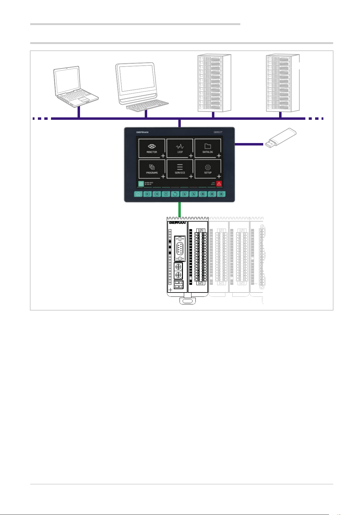
1.3. Hardware architecture
Ethernet
1. GENERAL DESCRIPTION
STNPSNTP
USB
CAN
4
1
2
3
4
5
1
PWRERR
6
6
9
C
D
B
A
9
8
7
6
5
4
C
D
B
A
9
8
7
6
5
4
F-GCANs
7
8
9
5
10
11
12
E
13
F
0
14
11
2
3
15
E
16
F
0
11
17
2
3
18
GATEWAY CAN bus
19
20
RUN
21
3
F-MIX
1
2
3
4
5
6
7
8
9
10
11
12
13
14
15
16
17
18
19
20
1
2
3
4
5
6
7
8
9
10
11
12
13
14
15
16
17
18
19
20
F-MIX F-MIX F-EU16F-EU16
1
2
3
4
5
6
7
8
9
10
11
12
13
14
15
16
17
18
19
20
1
2
3
4
5
6
7
8
9
10
11
12
13
14
15
16
17
18
19
20
80703B_MHW_2850T/3850T_02-2019_ENG
11
Page 14
1. GENERAL DESCRIPTION
1.4. 2850T controller
Main features
• Operator interface with color touch screen display, 3.5 "
• Up to 8 PID control loops
• Cascade, ratio and valve PID controls
• Profile programmer with ramps and retention; synchronous and asynchronous
• Up to 200 50-segment programmes
• 3 password protected user levels
• Energy meter (kWh)
• Configurable logic operations
• Configurable math functions
• Data Log with Real Time Clock
• Batch Report management
• Transcript of unencrypted files (CSV) or encrypted for
DataLog and production batches
• Setting up custom pages
• Management of active and historic alarms
• Current and cleared alarm management
• USB for data export and parameter cloning
• Control parameter advanced tuning
• Configurable analogue and digital I/O signals
• HMI/SCADA/PLC data exchange via Ethernet Modbus
TCP
• Message language selection
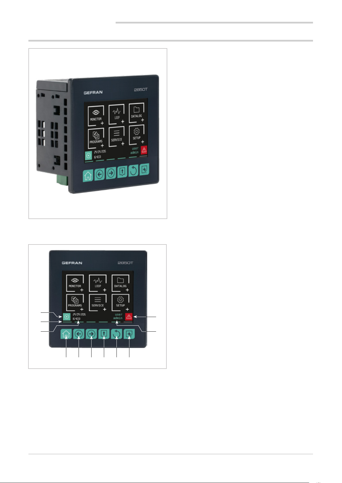
1.4.1. Display and keys
1
2
3 10
4 5 6 7 8 9
Figure 1 - 2850T display and key description
11
1. Shortcut icon (the landing page depends on the option
chosen):
• Controller with PROGRAMMER option: go to the
Program Monitor page that displays main program
information and lets you manage its execution.
• Controller with RECORDER option: go to the
Trend page that displays the set variable trends in
graphic format.
2. Lighted pressed key conformation.
3. Date and time indication.
4. Home page key: return to the main menu.
5. Left Page key: changes the page in the submenus with
multiple pages.
6. Right Page key: changes page in the submenus with
multiple pages.
7. Group Page key: go to the higher menu level.
8. Back key: return to the previous page.
9. Custom Page 1 button: go to first custom page
10. Authenticated user indication. The login page opens by
touching the indication.
11. Alarm Icon: blinks to indicate an alarm; tapping the
icon opens the page that lists current alarms.
12
80703B_MHW_2850T/3850T_02-2019_ENG
Page 15
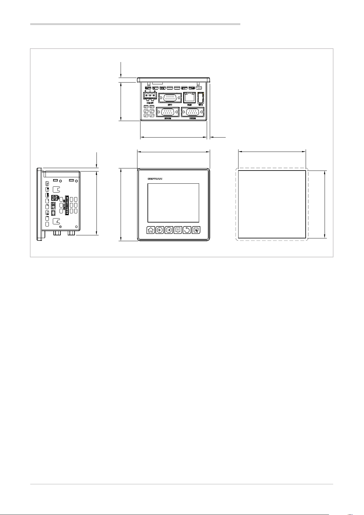
1.4.2. Dimensions and drilling templates
52.9 6.6
1. GENERAL DESCRIPTION
Dimensions in mm
4.5
88
91.6
100
2850T
100
4.2
Figure 2 - 2850T interface dimensions and drilling templates
93
Hole
93
80703B_MHW_2850T/3850T_02-2019_ENG
13
Page 16
1. GENERAL DESCRIPTION
1.5. 3850T controller
Main features
• Operator interface with color touch screen display, 7"
• Up to 16 PID control loops
• Cascade, ratio and valve PID controls
• Profile programmer with ramps and retention; synchronous and asynchronous
• Up to 250 50-segment programmes
• 3 password protected user levels
• Energy meter (kWh)
• Configurable logic operations
• Configurable math functions
• Data Log with Real Time Clock
• Batch Report management
• Transcript of unencrypted files (CSV) or encrypted for
DataLog and production batches
• Setting up custom pages
• Active and historical alarm management
• USB for data export and parameter cloning
• Control parameter advanced tuning
• Configurable analogue and digital I/O signals
• HMI/SCADA/PLC data exchange via Ethernet Modbus
TCP
• Message language selection
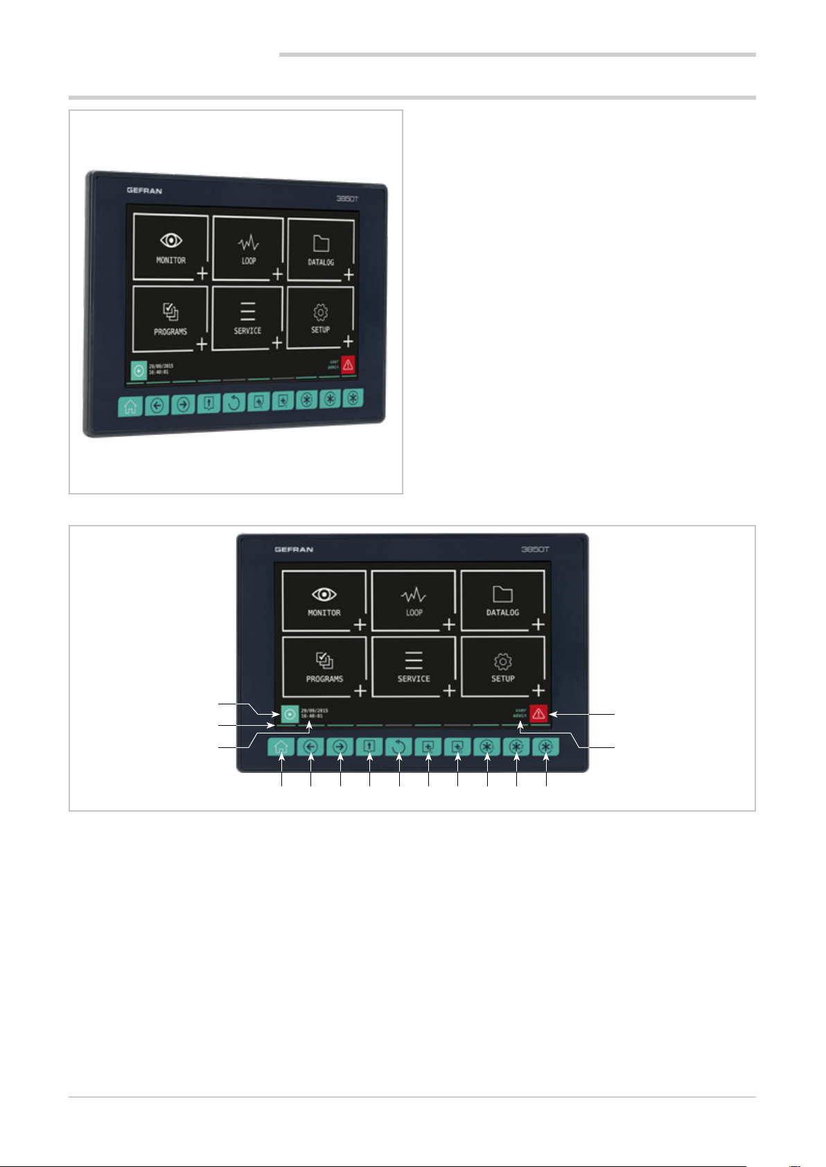
1.5.1. Display and keys
1
2
3 14
4 5 6 7 8 9 10 11 12 13
Figure 3 - 3850T display and key description
1. Shortcut icon (the landing page depends on the option
chosen):
• Controller with PROGRAMMER option: go to the
Program Monitor page that displays main program
information and lets you manage its execution.
• Controller with RECORDER option: go to the
Trend page that displays the set variable trends in
graphic format.
2. Lighted pressed key conformation.
3. Date and time indication.
4. Home page key: return to the main menu.
5. Left Page key: changes the page in the submenus with
multiple pages.
6. Right Page key: changes page in the submenus with
multiple pages.
7. Group Page key: go to the higher menu level.
15
8. Back key: return to the previous page.
9. Custom Page 1 button: go to first custom page.
10. Custom Page 2 button: go to second custom page.
11. Customizable Key Function 1: raise the digital variable
FUNCT_1.
12. Customizable Key Function 2: raise the digital variable
FUNCT_2.
13. Customizable Key Function 3: raise the digital variable
FUNCT_3.
14. Authenticated user indication. The login page opens by
touching the indication.
15. Alarm Icon: blinks to indicate an alarm; tapping the
icon opens the page that lists current alarms.
14
80703B_MHW_2850T/3850T_02-2019_ENG
Page 17
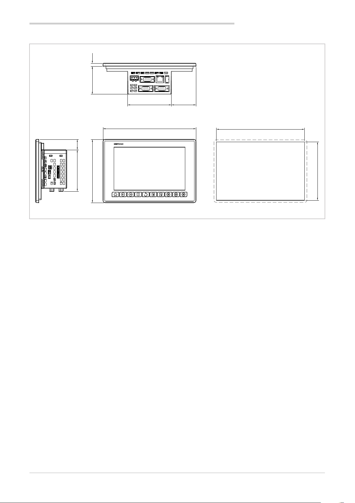
1.5.2. Dimensions and drilling templates
59.2 6.6
1. GENERAL DESCRIPTION
Dimensions in mm
22.4
88
93.3
198
134.4
52.4
3850T
Figure 4 - 3850T interface dimensions and drilling templates
187.5
Hole
124
80703B_MHW_2850T/3850T_02-2019_ENG
15
Page 18
1. GENERAL DESCRIPTION
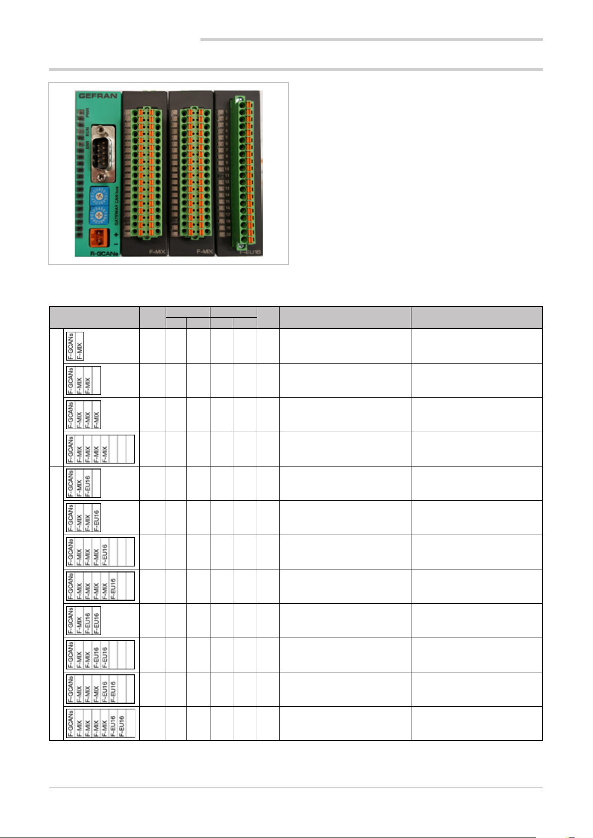
1.6. I/O modules
1.6.1. Compositions
Main features
• Available in the F-MIX versions (analog and digital
inputs and outputs) and F-EU16 (digital inputs and
outputs)
• F-MIX version: 4 analog inputs, 2 analog outputs, 8
digital inputs, 8 digital outputs
• F-EU16 version: 8 digital inputs, 8 digital outputs
• Standard composition from 1 to 4 F-MIX modules
(according to the controller model) and 1 F-GCANs
communication module
• Possibility to expand the standard composition with 1
or 2 F-EU16 modules
• Containers for 2, 4, 6 or 8 modules, according to the
chosen composition
• Container assembly on DIN 35 mm rail
Composition
Standard
Mod.
Analog Digital
1
IN OUT IN OUT
2 4 2 8 8 22 2850T-xx-04-xx-xx-xx-xx-xx-00-x-x 3850T-xx-04-xx-xx-xx-xx-xx-00-x-x
4 8 4 16 16 44 2850T-xx-08-xx-xx-xx-xx-xx-00-x-x 3850T-xx-08-xx-xx-xx-xx-xx-00-x-x
4 12 6 24 24 66 n/a 3850T-xx-12-xx-xx-xx-xx-xx-00-x-x
8 16 8 32 32 88 n/a 3850T-xx-16-xx-xx-xx-xx-xx-00-x-x
4 4 2 16 16 38 2850T-xx-04-xx-xx-xx-xx-xx-08-x-x 3850T-xx-04-xx-xx-xx-xx-xx-08-x-x
4 8 4 24 24 60 2850T-xx-08-xx-xx-xx-xx-xx-08-x-x 3850T-xx-08-xx-xx-xx-xx-xx-08-x-x
8 12 6 32 32 82 n/a 3850T-xx-12-xx-xx-xx-xx-xx-08-x-x
8 16 8 40 40 104 n/a 3850T-xx-16-xx-xx-xx-xx-xx-08-x-x
Tot.
I/O
2850T code 3850T code
4 4 2 24 24 54 2850T-xx-04-xx-xx-xx-xx-xx-16-x-x 3850T-xx-04-xx-xx-xx-xx-xx-16-x-x
with additional digital expansions
8 8 4 32 32 76 2850T-xx-08-xx-xx-xx-xx-xx-16-x-x 3850T-xx-08-xx-xx-xx-xx-xx-16-x-x
8 12 6 40 40 98 n/a 3850T-xx-12-xx-xx-xx-xx-xx-16-x-x
8 16 8 48 48 120 n/a 3850T-xx-16-xx-xx-xx-xx-xx-16-x-x
Notes
1) Container dimensions in modules
n/a = composition not available
16
80703B_MHW_2850T/3850T_02-2019_ENG
Page 19
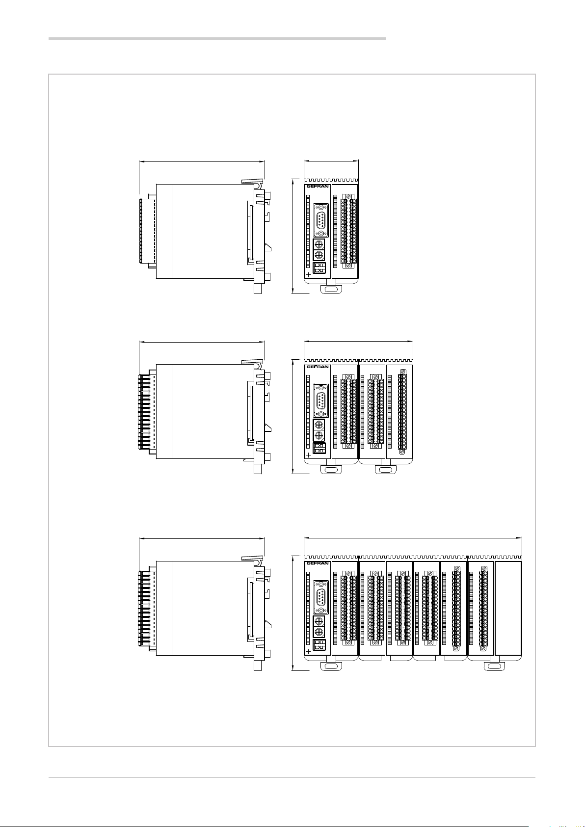
1.6.2. Dimensions
1. GENERAL DESCRIPTION
I/O 2 SLOT
I/O 4 SLOT
119,8
119,8
109,5109,5109,5
52
1
2
3
4
5
1
PWRERR RUN
6
6
7
8
9
9
5
10
11
12
C
D
B
E
13
A
F
9
0
8
14
1
1
7
2
6
3
5
4
15
C
D
B
E
A
16
F
9
0
8
131
17
7
2
6
5
4
18
GATEWAY CAN bus
19
1 2
4
20
3
F-GCANs
F-MIX
104
1
1
2
3
4
5
1
PWRERR
6
6
7
RUN
8
9
9
5
10
11
12
C
D
B
E
13
A
F
9
0
8
14
11
7
2
6
3
5
4
15
C
D
B
E
A
16
F
9
0
8
1
1
17
7
2
6
3
5
4
18
GATEWAY CAN bus
19
20
2
314
F-GCANs
F-MIX
1
2
2
3
3
4
4
5
5
6
6
7
7
8
8
9
9
10
10
11
11
12
12
13
13
14
14
15
15
16
16
17
17
18
18
19
19
20
20
F-EU16F-MIX
119,8
I/O 8 SLOT
Dimensions in mm
80703B_MHW_2850T/3850T_02-2019_ENG
1
1
2
2
3
3
4
4
5
1
PWRERR
6
RUN
9
5
C
D
B
E
A
F
9
0
8
1
1
7
2
6
3
5
4
C
D
B
E
A
F
9
0
8
1
1
7
2
6
3
5
4
GATEWAY CAN bus
21
4
3
F-GCANs
5
6
6
7
7
8
8
9
9
10
10
11
11
12
12
13
13
14
14
15
15
16
16
17
17
18
18
19
19
20
20
F-MIX
Figure 5 - I/O module container dimensions
208
1
1
2
2
3
3
4
4
5
5
6
6
7
7
8
8
9
9
10
10
11
11
12
12
13
13
14
14
15
15
16
16
17
17
18
18
19
19
20
F-MIX F-MIX F-EU16F-EU16F-MIX
20
1
1
2
2
3
3
4
4
5
5
6
6
7
7
8
8
9
9
10
10
11
11
12
12
13
13
14
14
15
15
16
16
17
17
18
18
19
19
20
20
17
Page 20

80703B_MHW_2850T/3850T_02-2019_ENG18
Page 21
Warning! The installation of the devices described in the manual must be carried out by qualified personnel, following the laws and regulations and in accordance with the instructions contained in this manual.
Before proceeding with the installation, check that the controller is intact and has not been damaged during transport. Also make sure that the package contains all the accessories listed in the supplied documentation, especially
the sealing gasket and fixing brackets.
Verify that the order code corresponds to the configuration required for the application in which the controller is
intended (the supply voltage, number and type of inputs and outputs). See chapter 10 - Order codes - to verify the
configuration corresponding to each order code.
Warning! If even one of the above-mentioned requirements (qualified technician, device intact, configuration not
matching that required) is not met, suspend installation and contact your Gefran dealer or Gefran Customer Service.
2.1. Controller assembly
2. INSTALLATION
2. INSTALLATION
2.1.1. General installation rules
The controller is designed for permanent indoor installations. It must be mounted in electrical cabinets, or in
machine or production process plant control panels, which
are able to protect the connectors on the back of the controllers.
Warning! The controller must NOT be installed in
dangerous environments (flammable or explosive).
It can be connected to elements that operate in
such environments only by means of suitable
types of interfaces in conformity with the applicable safety standards.
Warning! If the controller is used in applications
with risk of damage to persons or property, it is
essential to combine it with specific alarm devices. We recommend including the ability to check
alarm operation even during the normal operation
of the controller and the system or equipment
being monitored.
Sudden changes in temperature, freezing or condensation
or corrosive gases should not occur where the controller is
installed.
The controller can operate in environments with pollution
degree 2 (presence of non-conductive dust, only temporarily conductive due to potential condensation). Prevent the
device from being reached by metallic processing particles
or scraps as well as any condensation products.
The controller is sensitive to strong electromagnetic fields.
Avoid placing it near radio devices or other equipment that
can generate electromagnetic fields, such as high-power remote controllers, contactors, relays, thyristor power
groups (in particular, phase shift), motors, solenoids, transformers, high-frequency welders, etc.
2.1.2. Drilling Dimensions
For proper interface installation, respect the size of the single hole and the spacing between the adjacent holes shown
in the illustrations of the different models (“Figure 2 - 2850T
interface dimensions and drilling templates” on page 13
and “Figure 4 - 3850T interface dimensions and drilling
templates” on page 15).
Warning! The support on which the interface must
be mounted must have the following characteristics:
• be rigid and sturdy enough to support the
device and not bend during use;
• have a thickness between 1 and 4 mm, in
order to allow the device to be secured with
the supplied brackets.
2.1.3. Protection against dust and water
infiltration
The front of the interface provides IP65 protection. Therefore, the device can be installed in dusty environments or
subject to water sprays provided that:
• the compartment containing the interface is also dust
and water-tight;
• the support on which the interface is installed is perfectly smooth and without undulations in the front;
• the hole on the support scrupulously complies with the
indicated drilling dimensions;
• the interface well-secured to the support, to enable
the gasket inserted between the device and panel to
ensure water-tightness.
Warning! If not adequately protected, the interface protection degree is IP20 (rear housing and
connectors).
80703B_MHW_2850T/3850T_02-2019_ENG
19
Page 22
2. INSTALLATION
2.1.4. Vibration
The interface can withstand vibrations from 10 to 150 Hz,
20 m/s2 (2 g), in all directions (X, Y and Z).
If the device is mounted on a support that exceeds these
limits, a vibration suspension and damping system should
be provided.
2.1.5. Minimum clearances for ventilation
The temperature of the compartment that contains the
interface should not exceed, in any case, the 55° C (131 °F).
Never block the air vents.
The illustrations “Figure 2 - 2850T interface dimensions
and drilling templates” on page 13 and “Figure 4 - 3850T
interface dimensions and drilling templates” on page 15
indicate the minimum distances to be observed to ensure
device ventilation.
Tip. The lower the temperature in which the device
operates, the higher the life expectancy of its electronic components.
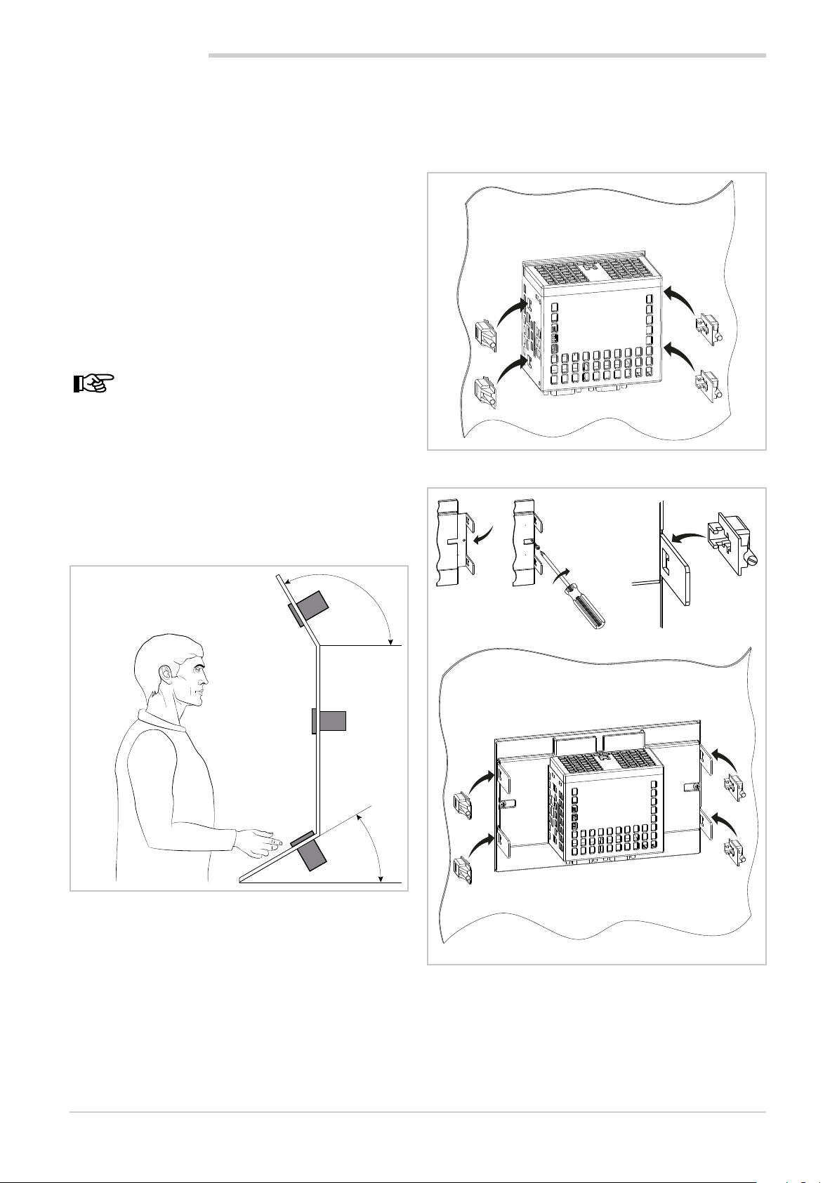
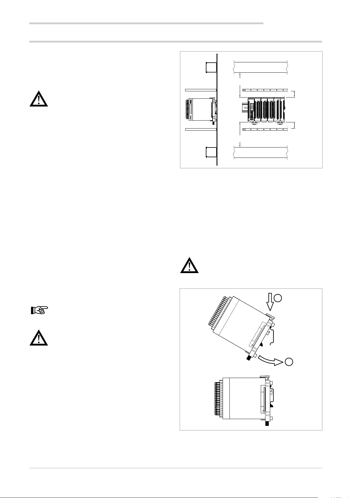
2.1.6. Positioning
The interface must be positioned so that the display is not
directly illuminated by the sun or by particularly intense light
sources. If necessary, shield direct beams, for example,
with an anti-reflective screen.
The interface angle should be between 30° and 120°, as
indicated in the figure.
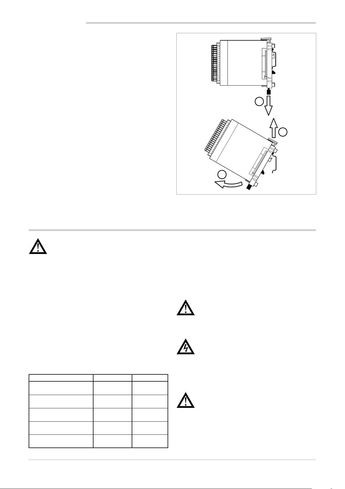
4. Tighten the screws to lock the device to the panel. The
tightening torque must be between 0.3 and 0.4 N m.
The following illustrations show how to secure the two
interface models.
Figure 7 - 2850T installation
Controllers not in scale
Figure 6 - Controller positioning
120 °
30 °
2.1.7. Panel Mount
1. Insert the tapered rubber gasket between the interface
and the panel. The gasket, supplied, it is essential to
ensure the degree of said frontal protection.
2. Insert the device into the hole previously drilled on the
panel.
3. Insert the supplied brackets on the back of the device.
For the 3850T model, first insert the square metal
brackets and secure with screws.
Figure 8 - 3850T installation
20
80703B_MHW_2850T/3850T_02-2019_ENG
Page 23
2.2. Installing I/O modules and Gefran communication
2.2.1. General installation rules
2. INSTALLATION
The I/O module groups are designed for permanent indoor
installations. They must be installed in control panels that
are able to protect the connectors on the modules.
Warning! The modules must NOT be installed in
dangerous environments (flammable or explosive).
They can be connected to elements that operate
in such environments only by means of suitable
types of interfaces in conformity with the applicable safety standards.
Sudden changes in temperature, freezing or condensation
or corrosive gases should not occur where modules are
installed.
Modules can operate in environments with pollution degree
2 (presence of non-conductive dust, only temporarily
conductive due to potential condensation). Prevent modules from being reached by metallic processing particles or
scraps as well as any condensation products.
2.2.2. Vibration
The modules can withstand vibrations from 10 to 150 Hz,
20m/s2 (2 g), in all directions (X, Y and Z).
If the modules are mounted on a support that exceeds
these limits, a vibration suspension and damping system
should be provided.
Raceway
Shield bar
Min 10 cm (3.94")
Min 3 cm
1
2
Mat. 3 4 7 5 7 6 5 0 5 9
V01
R-D/A4
F027062
3
4
5
PWRERR
6
7
RUN
8
9
10
11
12
D
C
B
E
13
A
F
9
0
8
14
1
1
7
2
6
3
5
4
15
D
C
B
E
A
16
F
9
0
8
1
1
17
7
2
6
3
5
4
18
GATEWAY CAN bus
19
20
21
4
3
R-GCANs
F-MIX
2
2
3
3
4
4
5
5
6
6
7
7
8
8
9
9
10
10
11
11
12
12
13
13
14
14
15
15
16
16
17
17
18
18
19
19
20
20
F-MIX F-MIX F-EU16F-EU16
2
3
4
5
6
7
8
9
10
11
12
13
14
15
16
17
18
19
20
1
1
1
(1.18")
1
2
3
4
5
6
7
8
9
10
11
12
13
14
15
16
17
18
19
20
Min 3 cm
(1.18")
Shield bar
Min 10 cm (3.94")
Raceway
Figure 9 - Horizontal positioning
2.2.5. Module installation
The modules must be mounted on metallic and grounded
DIN 35 mm (1,38”) rail inside switchboards.
To secure the modules:
1. insert the top of the module hook on the DIN rail;
2. rotate the module to the vertical position, pressing until
you hear the "clack" which indicates that the lower
slide hook is attached to the DIN rail.
2.2.3. Minimum clearances for ventilation
The temperature of the compartment that contains the
modules should not exceed, in any case, the 55° C (131 °F).
Never block the air vents.
Tip. The lower the temperature in which the modules operate, the higher the life expectancy of their
electronic components.
Warning! Forced module cooling (i.e. with a fan)
can cause measurement errors.
2.2.4. Positioning
The modules can only be mounted horizontally.
When positioning the modules, make sure that there is
sufficient air circulation around them. Figure 9 shows the
minimum distances from adjacent walls that must be respected for ventilation.
Warning! There is a spring contact at the back
of each module to ground it through the DIN rail.
There will be no electric continuity with the ground
if the rail is not conductive or is not connected.
1
2
80703B_MHW_2850T/3850T_02-2019_ENG
Figure 10 - DIN rail mounting
21
Page 24
2. INSTALLATION
2.2.6. Removing Modules
To remove the modules:
1. pull down lower slide lock to release the module;
2. rotate the module outwards;
3. remove the top part of the module hook from the DIN
rail.
1
3
2
2.3. Connections
Warning! Please remember that failing to follow
the instructions below could lead to electrical safety and electromagnetic compatibility problems, as
well as void the warranty.
2.3.1. General rules for connections
1. The externally connected circuits must have double
insulation.
2. In the case of shielded cables, the shield must be
grounded at one point only, possibly close to the I/O
module group.
3. Input cables must be physically separated from output
ones and the power connections.
4. Do not connect the unused I/O contacts.
2.3.2. Electromagnetic Compatibility (EMC)
The most stringent generic standards were used for electromagnetic compliance, using the following experimental
configuration:
Connection Cable section Length
Voltage 1 mm
Serial port 0,35 mm
Thermocouple 0,8 mm
Potentiometer, linear,
"PT100" thermistor
Digital inputs/outputs 1 mm
2
(17 AWG)
(18 AWG)
1 mm2
(17 AWG)
2
(17 AWG)
2
2
1 m
(39.37”)
3.5 m
(137.79”)
5 m (196.85”)
compensated
3 m
(9.84”)
3.5 m
(137.79”)
Figure 11 - Removal from DIN rail
2.3.3. Cables
Always make connections using cables suited to the voltage and current limits specified in the Technical Specifications.
For connections, use copper wires with insulation for
60/75° C (140/167 °F). For non power connections, do not
use twisted and shielded cables.
Warning! Anchor cables, at least in pairs, so that
the mechanical stresses do not discharge on the
terminal block connections.
2.3.4. Voltage
Warning! Before powering the interface and I/O
module group, make sure that the supply voltage
corresponds to that on the device plates.
The 24 VDC supply must come from a Class II source or
limited energy low voltage. The power supply must use
a separate line from that used for the electromechanical
power devices and low-voltage power cables must follow a
separate path from the plant or machine power cables.
Warning! Make sure that the grounding connection is efficient. A missing or ineffective ground
connection can cause unstable device operations
due to excessive environmental disturbances. In
particular, check that:
• the voltage between ground and earth is < 1 V;
• the ohmic resistance is < 6 Ω.
22
80703B_MHW_2850T/3850T_02-2019_ENG
Page 25
Ensure that the 24 VDC power supply is fitted with a switch,
or that there is a bipolar switch on the line that connects it
to the mains voltage, in order to easily cut-off power to the
controller in case of need.
2.3.5. Input and output connections
The I/O module input and output lines should be separated
from the power line.
To avoid disturbances, the I/O module input and output
cables must be kept away from the power cables (high
voltage or large current).
Input, output and power cables must not be laid in parallel.
Shielded cable or separate cable ducts are recommended.
Warning! If the controller is connected to NON
isolated electrical devices (i.e. thermocouples), the
ground connection must be made with a specific
conductor to prevent it from being directly through
the machine structure.
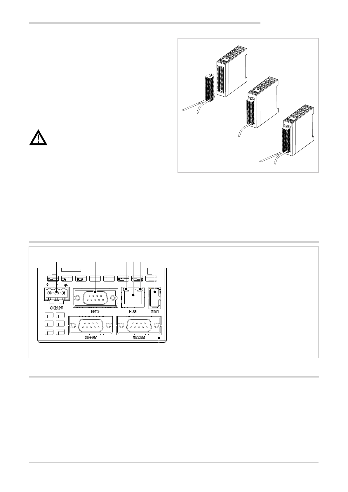
The connectors are polarised and accept wires of between
0.2 and 1,5 mm2 (from 24 to 15 AWG).
Insert the wire in the connector hole corresponding to the
terminal that is to be connected. After inserting the conductors, push the connector into the module.
To disconnect a wire, place a screwdriver into the slot next
to the conductor, to release the retaining spring.
The following figure shows how to insert or remove a wire
to/from the connector.
2. INSTALLATION
Figure 12 - I/O Connectors
2.4. Interface connection diagram
1 2 3 4 5 6
7
2.5. Ethernet Connections
Personal computers, servers and multi-purpose controllers
can communicate through the Ethernet connection. This
means that you can:
• control one or more multi-purpose controllers through
one or more personal computers;
• store data produced or used by one or more multi-purpose controllers on one or more servers and have them
readily available;
• keep one or more multi-purpose controllers time
synced via an NTP (Network Time Protocol).
1. Power supply 24 VDC ±25% Also connect the connector to the ground wire.
2. CAN Port DB9 M.
3. Green LED indicates active Ethernet connection.
4. RJ45 Ethernet port 10/100 Mbit/s.
5. Yellow LED indicates data transfer in progress.
6. USB port type A.
NTP servers allow computer systems to be synchronised,
meaning all connected devices will have the same time, referring to a precise external clock and not only the internal
clock, less precise.
Synchronisation enables a value offset of less than one
millisecond for systems belonging to the same network and
in any case less than a few hundred milliseconds for remote
networks.
80703B_MHW_2850T/3850T_02-2019_ENG
23
Page 26
2. INSTALLATION
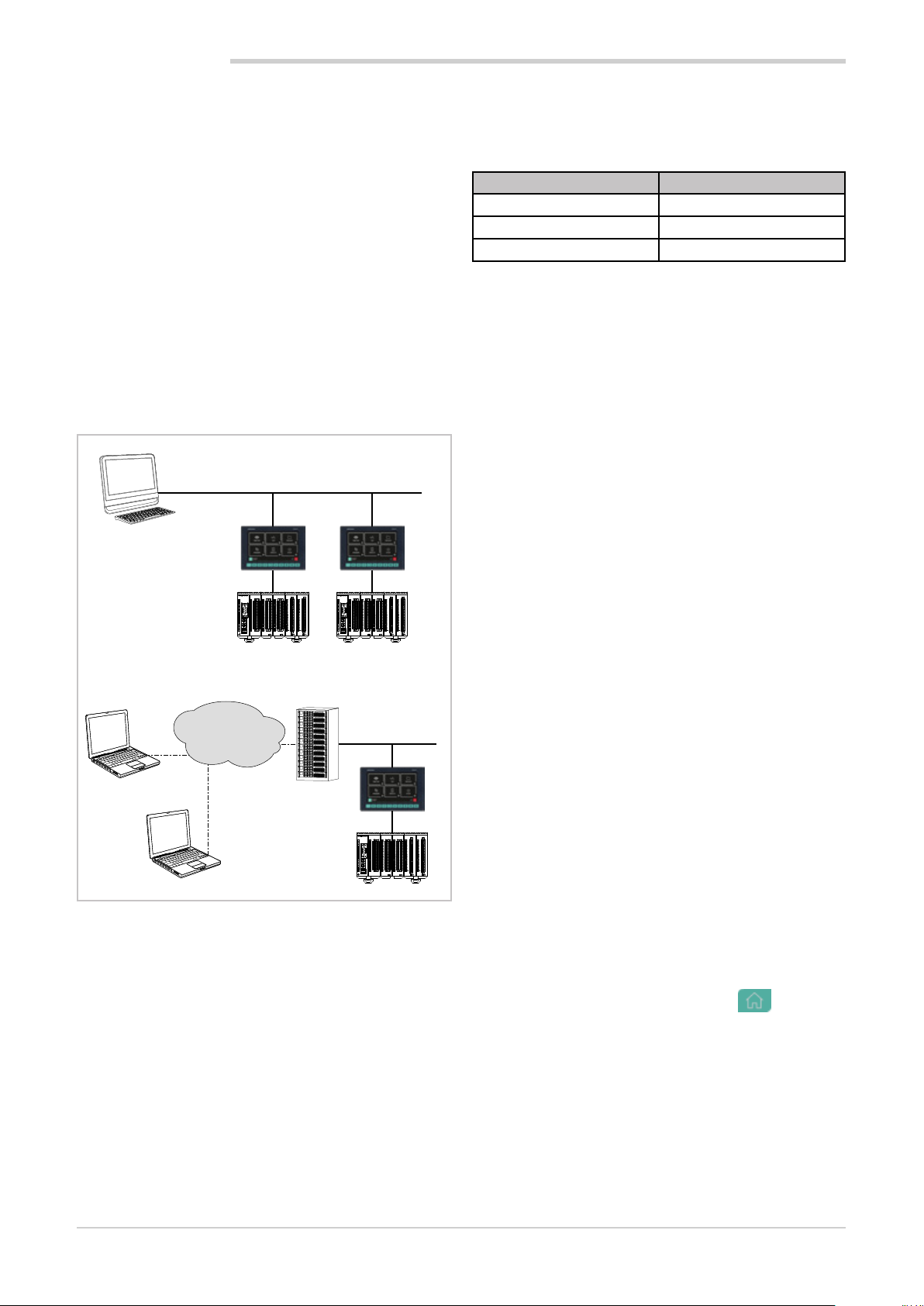
2.5.1. Private networks and public networks
The connection networks may be private or public.
A private network is a closed network with no connections
to the outside world and is intrinsically more secure.
The public network (Internet), in contrast, allows you to access the devices connected to the network from anywhere
in the world but, because of this, it is less secure.
Finally, there is the option of connecting a private network
to a public network through a device called a firewall, which
keeps them isolated except for duly authorised traffic.
In this type of configuration, a private network is often identified with the acronym LAN (Local Area Network) and the
public with the acronym WAN (Wide Area Network). Other
ways to identify them are intranet and extranet.
Note that the private network can also be constituted by a
single device.
Figure 13 3 shows the different types of networks.
PRIVATE NETWORK
Ethernet
Technician
(PC Windows)
CANCAN
1
1
1
1
1
1
1
1
1
2
2
2
2
2
3
3
3
3
3
4
4
4
4
4
5
5
5
5
5
1
PWRERR
6
6
6
6
6
7
7
7
7
RUN
8
8
8
8
9
9
9
9
9
5
10
10
10
10
11
11
11
11
12
12
12
12
D
C
B
E
13
13
13
13
A
F
9
0
8
14
14
14
14
11
7
2
6
3
5
4
15
15
15
15
D
C
B
E
A
16
16
16
16
F
9
0
8
11
17
17
17
17
7
2
6
3
5
4
18
18
18
18
GATEWAY CAN bus
19
19
19
19
20
20
20
20
21
4
3
F-MIX
F-MIX F-MIX F-EU16F-EU16
R-GCANs
PWRERR
6
7
RUN
8
9
10
11
12
13
14
15
16
17
18
19
20
21
4
3
1
2
2
2
2
2
3
3
3
3
3
4
4
4
4
4
5
5
5
5
5
1
6
6
6
6
6
6
7
7
7
7
7
8
8
8
8
8
9
9
9
9
9
9
5
10
10
10
10
10
11
11
11
11
11
12
12
12
12
12
D
C
B
E
13
13
13
13
13
A
F
9
0
8
14
14
14
14
14
11
7
2
6
3
5
4
15
15
15
15
15
D
C
B
E
A
16
16
16
16
16
F
9
0
8
11
17
17
17
17
17
7
2
6
3
5
4
18
18
18
18
18
GATEWAY CAN bus
19
19
19
19
19
20
20
20
20
20
F-MIX
F-MIX F-MIX F-EU16F-EU16
R-GCANs
Controller Controller
PUBLIC NETWORK
INTERNET
Ethernet
Remote service
CAN
1
1
1
1
1
2
2
2
2
2
3
3
3
3
3
4
4
4
4
4
5
5
5
5
5
1
PWRERR
6
6
6
6
6
6
7
7
7
7
7
8
8
8
8
8
9
9
9
9
9
9
5
10
10
10
10
10
11
11
11
11
11
12
12
12
12
12
D
C
B
E
13
13
13
13
13
A
F
9
0
8
14
14
14
14
14
11
7
2
6
3
5
4
15
15
15
15
15
D
C
B
E
A
16
16
16
16
16
F
9
0
8
11
17
17
17
17
17
7
2
6
3
5
4
18
18
18
18
18
GATEWAY CAN bus
19
19
19
19
19
20
20
20
20
20
F-MIX
F-MIX F-MIX F-EU16F-EU16
R-GCANs
Remote technician
RUN
21
4
3
Controller
Figure 13 - Types of networks
2.5.2. Firewall
The firewall is a physical device or a software application
that isolates a device or a network section from the rest of
the connection network.
Several firewalls may need to be crossed to reach a device.
For example, there might be a firewall between the corporate LAN and the Internet and another firewall that isolates
the device from the corporate network.
To access a multi-purpose controller behind a firewall you
need to configure the access channels or firewall traffic
rules and implement connections via VPN (Virtual Private
Network) or directly through a modem.
Consult the corporate IT system administrator to properly
configure firewalls or know the parameters to implement a
VPN or connect via modem.
In order to connect to an external multi-purpose controller
and ensure the proper operations of all the services, the
following ports need to be open (communicate the list to
the IT administrator):
Port Service
20, 21 FTP
502 Modbus TCP
5500, 5800, 5900 VNC
2.5.3. Router
In cases of particularly complex or extended Ethernet networks or that are subject to intense broadcast type traffic,
the connection to the 2850T and 3850T controllers must
be isolated. This is achieved by structuring the network
into subnets (corporate/machine), or by limiting the TCP/IP
traffic actually necessary for hubs or services.
This rule, in general, should be also be observed when
connecting 2850T and 3850T controllers in small sized
networks or with remote access systems.
The recommended solution is to connect the 2850T and
3850T controllers via a router.
The router is a layer 3 device that allows you to route the
communication packets between different networks, meaning to determine specific port outputs package that arrived
based on the target IP address.
The use of router ensures that the Ethernet traffic to or from
the 2850T and 3850T controllers is filtered and remains
isolated from the rest of the corporate network or from the
external network.
2.5.4. VNC (Virtual Network Computing)
You can check the multi-purpose controller remotely using
a VNC connection with a personal computer. The RFB protocol used is public domain.
With the VNC connection, the multi-purpose controller
assumes the host function and the personal computer the
client, where the connected multi-purpose controller interface is exactly reproduced.
Every action (clicking with the mouse, settings, etc.) performed on the reproduction of the interface display that
appears on the personal computer is faithfully replicated on
the controller and vice versa. The pages on the display and
computer monitor are synchronised in real time.
2.5.5. VNC Server
The VNC server is part of multi-purpose controller operations. The VNC server is disabled by default. To enable it:
1. Log in as administrator. For more information on the
login procedure, refer to the section “4.1. Login password” on page 35.
2. Open the Home Page by pressing the
selectService.
3. Select Setup
4. Select Configuration on the page that opens. Note the
device IP address that is used to configure access
through clients. If the network addresses have not yet
been set, see paragraph “4.14.2.2. Network Configuration” on page 72.
5. Select Network.
6. Select NTP VCN Configuration.
button and
24
80703B_MHW_2850T/3850T_02-2019_ENG
Page 27
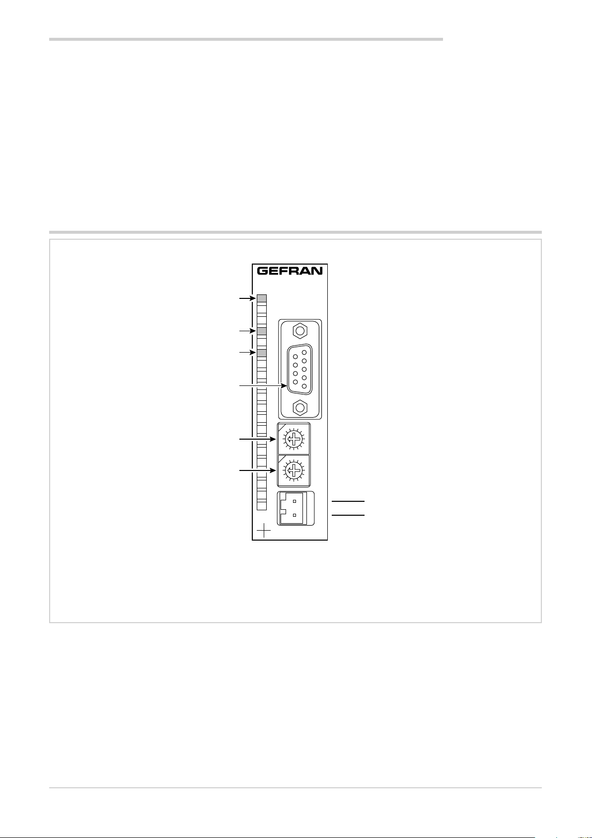
2. INSTALLATION
8
0
7
F
5
D
3
B
1
9
4
C
6
E
2
A
8
0
7
F
5
D
3
B
1
9
4
C
6
E
2
A
PWRRUNERR
+
-
GATEWAY CAN bus
F-GCANs
1 2
4 3
+
-
7. On the page that opens, enable VNC by ticking the
appropriate box and enter the password that will be
used to login. The password can be up to 34 charac-
The viewer can handle multiple concurrent connections,
but an excessive number of connections can cause image
refresh to slow.
ters long.
2.5.6. VNC Viewer
There are several programs that turn a personal computer
into a VNC client.
In addition to personal computers there are VNC viewers for
other devices such as tablets and smartphones.
2.6. F-GCANs communication module connection diagram
CAN bus connection
Yellow LED: +24 VDC power supply on
Green LED: module operating status *
*) on = module on
flashing = module not on
**) on = generic error
flashing = communication error
Red LED: module alarm **
CAN bus connector
Unused
Unused
Power supply 24 VDC ±25% 2 A max
80703B_MHW_2850T/3850T_02-2019_ENG
25
Page 28
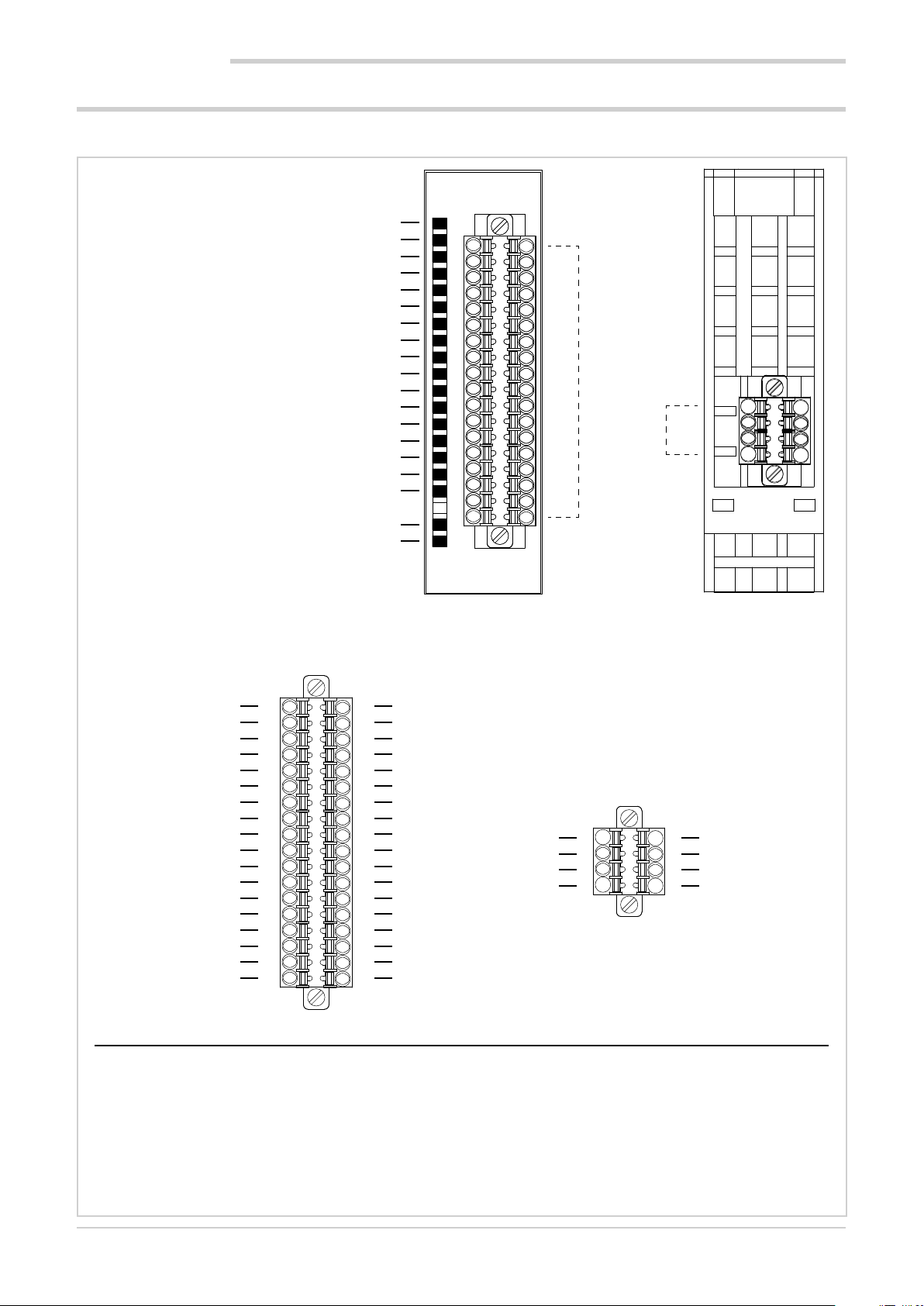
2. INSTALLATION
2.7. F-MIX module connection diagrams
2.7.1. General layout
Yellow LED: +24 VDC external power supply on
Green LED: digital input DI1 status ON
Green LED: digital input DI2 status ON
Green LED: digital input DI3 status ON
Green LED: digital input DI4 status ON
Green LED: digital input DI5 status ON
Green LED: digital input DI6 status ON
Green LED: digital input DI7 status ON
Green LED: digital input DI8 status ON
Green LED: digital output DO1 status ON
Green LED: digital output DO2 status ON
Green LED: digital output DO3 status ON
Green LED: digital output DO4 status ON
Green LED: digital output DO5 status ON
Green LED: digital output DO6 status ON
Green LED: digital output DO7 status ON
Green LED: digital output DO8 status ON
Green LED: module operating status *
Red LED: module alarm
A
1
2
1
3
4
5
6
7
8
9
10
11
12
13
14
15
16
17
18
35
19
20
2
1
7
Digital inputs
36
Digital outputs - Analog inputs - Analog outputs
2
8
F-MIX
+VI24
DO1
DO3
DO5
DO7
GNDI
AO1
TA1
VP1
-AI1
+AI1
AI1mA
VS1
GNDI
VP3
-AI3
+AI3
AI3mA
1
3
5
7
9
11
13
15
17
19
21
23
25
27
29
31
33
35
DI = Digital input
DO = Digital output
AI = Analog input
AO = Analog output
+VI24 = 24 V voltage
GNDI = 0 V voltage
TA = input from a current transformer
VP = Potentiometer power
VS = Extensometer input
2
4
6
8
10
12
14
16
18
20
22
24
26
28
30
32
34
36
GNDI
DO2
DO4
DO6
DO8
GNDI
AO2
TA2
VP2
-AI2
+AI2
AI2mA
VS2
GNDI
VP4
-AI4
+AI4
AI4mA
B
DI2
DI1
DI3
DI5
DI7
*) Fast flashing = module on
slow flashing = module awaiting configuration (not operating)
1
3
5
7
2
DI4
4
DI6
6
DI8
8
26
80703B_MHW_2850T/3850T_02-2019_ENG
Page 29

2. INSTALLATION
A
2.7.2. Voltage
Voltage
A
+24 VDC 2
2.7.3. Digital inputs
Digital inputs DI1 ... DI8
+
24 VDC
±25%
-
2.7.4. Analog inputs
Potentiometer inputs
1
3
5
7
9
4
6
8
10
A
1
3
5
7
9
2
GND
4
6
8
10
A
17
AI1
19
21
23
25
27
29
AI3
31
33
35
Type J, K, R, S, T thermocouple inputs
A
AI1 AI2
-
19
+
21
23
25
AI3 AI4
27
29
-
31
+
33
35
18
20
22
24
26
28
30
32
34
36
20
22
24
26
28
30
32
34
36
DI1
DI3
DI5
DI7
GND
1
3
5
7
Inputs RTD PT100/PT1000 - 4-wire connection
A
11
13
AI1
15
17
19
21
23
25
AI3
27
29
31
33
35
B
DI2
2
DI4
4
DI6
6
DI8
8
Inputs RTD PT100/PT1000 - 3-wire connection
11
13
AI1
15
17
19
21
23
25
AI3
27
29
31
33
35
AI2
Inputs RTD PT100/PT1000 - 2-wire connection
12
14
16
18
20
22
24
26
28
30
32
34
36
12
14
16
18
20
22
24
26
28
30
32
34
36
AI2
AI4
AI2
AI4
A
AI4
11
13
AI1
15
17
19
21
23
25
AI3
-
+
27
29
31
33
35
-
+
12
14
16
18
20
22
24
26
28
30
32
34
36
AI2
AI4
80703B_MHW_2850T/3850T_02-2019_ENG
27
Page 30
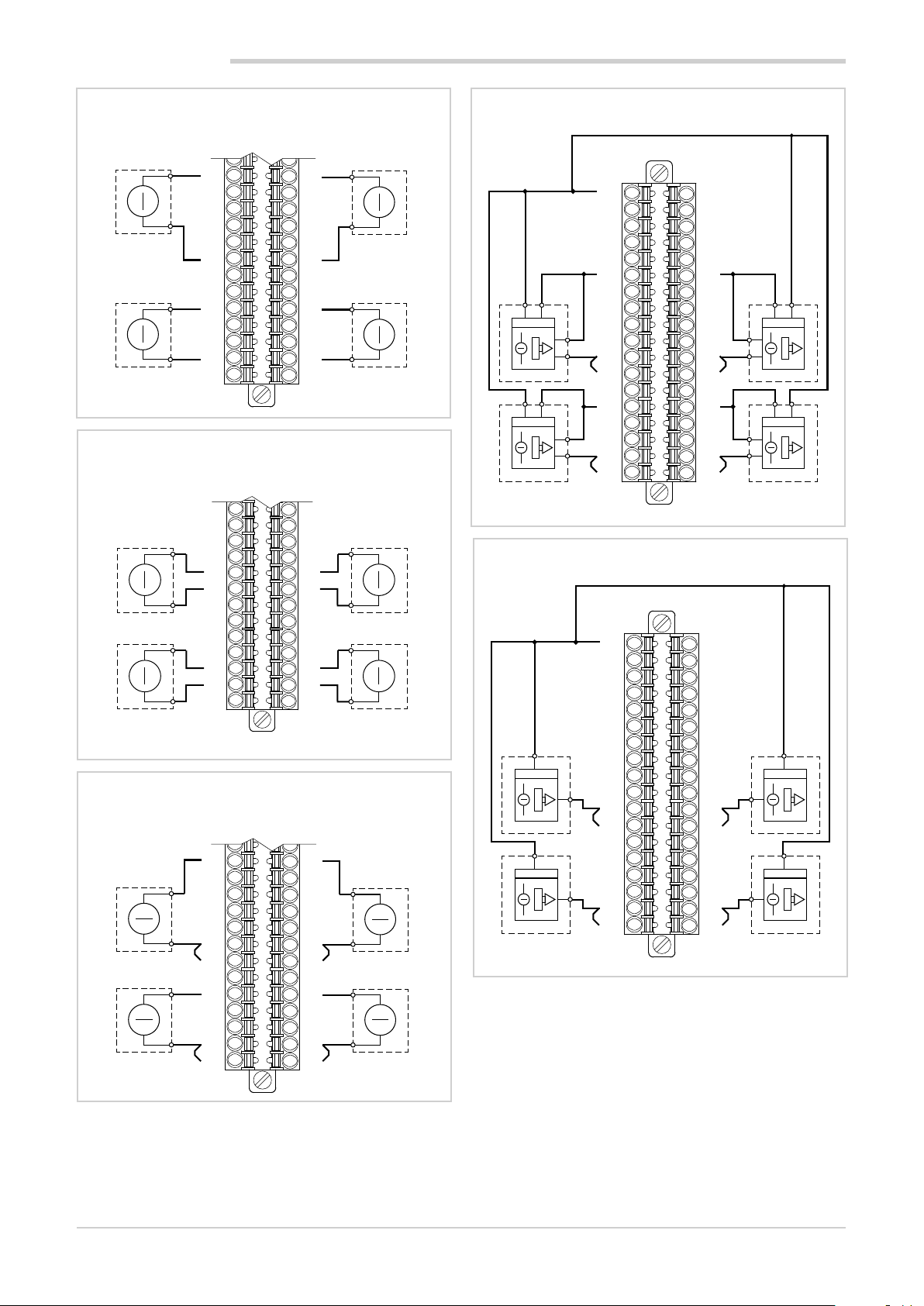
2. INSTALLATION
Single-ended voltage inputs
A
11
-
AI1
+
13
15
17
19
21
23
25
27
-
AI3
+
29
31
33
35
Differential voltage inputs
12
14
16
18
20
22
24
26
28
30
32
34
36
-
+
-
+
A
11
13
15
17
-
AI1 AI2
+
19
21
23
25
27
29
-
AI3 AI4
+
31
33
35
Current inputs
12
14
16
18
20
22
24
26
28
30
32
34
36
-
+
-
+
A
12
14
16
18
20
22
24
26
28
30
32
34
36
-
+
-
+
AI1
AI3
11
13
15
-
17
19
+
21
23
25
27
-
29
31
+
33
35
AI2
AI4
AI2
AI4
Amplified current transducer inputs - 4-wire connection
A
1
3
5
7
9
11
AI1
+ -
Power supply
AI3
+ -
Power supply
+
-
+
-
13
15
17
-
19
21
+
23
25
27
29
-
31
33
+
35
Amplified current transducer inputs - 2-wire connection
2
4
6
8
10
12
14
16
18
20
22
24
26
28
30
32
34
36
Power supply
-
+
-
+
Power supply
-
+
-
+
AI2
AI4
A
2
4
6
8
10
12
14
16
18
20
22
24
26
28
30
32
34
36
Power supply
+
Power supply
+
+
+
-
+
+
-
AI1
Power supply
AI3
Power supply
1
3
5
7
9
11
13
+
+
-
15
17
+
19
21
23
25
+
27
29
+
+
-
31
33
35
+ -
+ -
AI2
AI4
28
80703B_MHW_2850T/3850T_02-2019_ENG
Page 31

2. INSTALLATION
Extensometer inputs
11
AI1
13
15
17
19
21
23
25
27
29
31
33
35
AI3
Current transformer inputs
1
9
11
max
50 mA RMS
13
15
17
A
A
12
14
16
18
20
22
24
26
28
30
32
34
36
2
10
12
14
16
18
AI2
AI4
TA2TA1
max
50 mA RMS
2.7.5. Digital outputs
Digital outputs DO1 ... DO8
LOAD
DO1
24 VDC
±25%
+
-
DO3
DO5
DO7
LOAD
LOAD
LOAD
11
2.7.6. Analog outputs
Analog outputs AO1 ... AO8
11
13
AO1
LOAD
A
1
3
5
7
9
2
LOAD
4
6
8
10
12
LOAD
LOAD
LOAD
DO2
DO4
DO6
DO8
GND
A
12
14
LOAD
AO2
2.8. F-EU16 digital I/O module connection diagram
Yellow LED: power supply for DO1-DO4 on
Green LED: output DO1 status ON
Green LED: output DO2 status ON
Green LED: output DO3 status ON
Green LED: output DO4 status ON
Yellow LED: power supply for DO5-DO8 on
Green LED: output DO5 status ON
Green LED: output DO6 status ON
Green LED: output DO7 status ON
Green LED: output DO8 status ON
Green LED: input DI1 status ON
Green LED: input DI2 status ON
Green LED: input DI3 status ON
Green LED: input DI4 status ON
Green LED: input DI5 status ON
Green LED: input DI6 status ON
Green LED: input DI7 status ON
Green LED: input DI8 status ON
Red LED: module alarm
1
2
3
4
5
6
7
8
9
10
11
12
13
14
15
16
17
18
19
20
F-EU16
+24 VDC per DO1-DO4
+24 VDC per DO5-DO8
GND
GND
LOAD
LOAD
LOAD
LOAD
LOAD
LOAD
LOAD
LOAD
DO1
DO2
DO3
DO4
DO5
DO6
DO7
DO8
- +
24 VDC
±25%
+
24 VDC
-
DI1
DI2
DI3
DI4
DI5
DI6
DI7
DI8
±25%
80703B_MHW_2850T/3850T_02-2019_ENG
29
Page 32

2. INSTALLATION
2.9. Touch Screen calibration procedure
Step 1 – Power off the unit and locate the “SEL” rotary
switch on the right side of the unit case
Step 2 – set the switch to the “E” position
Step 4 – Proceed to calibrate all corners and screen centre
in the same way:
Upper right corner
Step 3 – Power on the unit ; the touch-screen calibration
page should appear
Touch the cross-hair to calibrate the upper left corner
position.
It is recommended to use a pen tip rather than fingers to
improve accuracy.
Lower right corner
Lower left corner
30
80703B_MHW_2850T/3850T_02-2019_ENG
Page 33

Centre
Step 5 – After the “center” calibration please wait until the
unit returns automatically to main page
2. INSTALLATION
Step 6 – Reset “SEL” switch to “0” position (it is not
necessary to power-off the unit)
The calibration procedure is over
80703B_MHW_2850T/3850T_02-2019_ENG
31
Page 34

80703B_MHW_2850T/3850T_02-2019_ENG32
Page 35

3. COMMISSIONING
3.1. Display information and key use
The general description of the display and the keys of the
individual models is contained in the paragraphs “1.4.1.
Display and keys” on page 12 for the 2850T interface
and “1.5.1. Display and keys” on page 14 for the 3850T
interface.
3.1.1. Navigation
To navigate the menus and sub-menus, use the touch
screen display and 6 or 10 keys below the display.
To select or set parameters and for all configuration tasks,
only use the touch screen display.
3.1.2. Virtual keyboards
The alphanumeric keyboard or the numeric keypad appears
on the display when you need to enter text or numeric values appear on the display, respectively.
3. COMMISSIONING
Figure 15 - Numeric keypad
The keyboards have a window at the top where the entered
text appears.
Use the following keys to save, delete, cancel or change
the keyboard:
Stores the entered text or value, as it appears in the
window, and closes the virtual keyboard.
Figure 14 - Alphanumeric keyboard
3.2. Behavior when turned on
When turned on, the multi-purpose controller loads the
operating system and the default program. "Loading ..."
appears on the screen.
When finished loading, the display turns off and "starting
..." appears after a few seconds to indicate that the default
program is launched.
Deletes the last character entered. The virtual keyboard
remains open.
Closes the virtual keyboard, discarding any entered
text or value that appears in the window.
Changes the display of the alphanumeric keyboard
keys.
When the start-up phase ends the display indicates the
Monitor Program page. The multi-purpose controller is now
fully operational.
Any communication errors between I/O modules and the
terminal are indicated by the Alarm icon in the pages.
Touch the icon to view the list of alarms and review specific
alarms.
80703B_MHW_2850T/3850T_02-2019_ENG
33
Page 36

3. COMMISSIONING
3.3. First start-up
The diagram illustrates controller operations at first start-up.
Power ON
Controller start
I/O module Installation
Loading
ON
Slow blink
Fast blink
F-GCANs
PWRRUNERRPWRRUNERRPWRRUNERRPWRRUNERR
F-GCANs
Alarm signal triggered.
The type of alarm can
be examined in the
alarm page.
Check options
Loading options
Running functions
False
Communicating
with I/O modules?
True
I/O channel signal type config-
uration
ON
Slow blink
Fast blink
Launch
F-GCANs
ON
Slow blink
OFF
Controller on
F-GCANs
ON
ON
OFF
If there are no signals
from the I/O channels,
check their electrical
connections.
34
False
I/O channel sig-
nals?
Run
True True
PID Option?
False
RECORDER Op-
tion?
False
True
80703B_MHW_2850T/3850T_02-2019_ENG
PID loop HW resource configu-
ration and type of control
Configuration number and type
of channels for storage
Page 37

4. MENU AND CONFIGURATION
4. CONFIGURATION
A high level of knowledge of problems and techniques associated with the controlled process is required to properly
set the parameters needed to configure the controller so
that it meets the application requirements.
If you are unsure of your skills, or you are not fully aware of
the consequences that could result from incorrect parameter settings, we do not recommend you proceed with the
configuration.
4.1. Login password
Access to the menus is protected by 3 password levels:
Operator, Maintenance and OEM, listed from the one with
lowest privileges to that with full access to all controller
functions and parameters.
The level determines which menus, with their functions and
parameters, you can navigate.
The first level (level 0), Operator, provides access to submenus and more operational parameters, namely the ones
that most affect the daily monitored machine or plant
operations.
The second level (level 1), Maintenance, provides access to
the sub-menus and the parameters dedicated to the configuration of device hardware resources.
Warning! Before commissioning the controller the
user must ensure the parameters are set correctly
to avoid damage to persons or property.
The default password values are:
• Level 0: free access (no user or password)
• Level 1: User = service, Password = 5678
• Level 2: User = admin, Password = 1234
Authentication with password level 0 has no time limit,
authentication with level 1 and 2 passwords expire after 30
minutes.
The name of the person currently logged in may be read in
the lower right hand corner of the display.
Passwords can be created and modified. See the paragraph in this regard “4.15.6. USER CFG sub-menu” on
page 90.
The third level (level 2), OEM, is reserved to the manufacturer who has included the multi-purpose controller in its
machinery or plant.
4.2. Display, configuration and management
Specific menus are used to view information on the
multi-purpose controller and operations it performs, to configure the device and its functions and, ultimately, to manage the machine or process controlled by the controller.
Each controller parameter, function or process can be managed by one or more menus.
Available trees and menu items vary depending on the controller model. The individual display or configuration pages,
however, are the same for all models.
The menu structure shown in detail is that of the controller
complete with all the options.
For other versions, refer to the graphical representations of
the different menus (paragraphs “4.7. Controller menu with
GETLogic and GETview options” on page 40, “4.8. Tool
menu with GETLogic, GETview and recorder options” on
page 41 and “4.9. Controller menu with GETLogic, GETview and recorder options” on page 42), from which you
can trace back to the individual information and configuration pages available.
80703B_MHW_2850T/3850T_02-2019_ENG
35
Page 38

4. CONFIGURATION
4.3. Monitor Program
The Monitor Program page is the page that shows the most
important information of the loaded program. It is also the
page which, by default (editable), appears at the end of the
multi-purpose controller start-up procedure. Through this
page, you can also manage the program (start, stop, etc).
1
2
3
4
5
The Monitor Program page is always accessible:
• using the Home Page Monitor Monitor Prog
menu or more simply
• by touching the
lower left corner of the display.
13141516
12
12
key permanently displayed in the
11
10
9
8
7
6
1. Viewing the signal to run the program.
2. START button: starts the program. A pop-up window opens when you touch the button displaying the
production batch number and you can enter a name.
To enter this information, touch the appropriate fields
and use the virtual keyboard that appears. The data is
not mandatory, but entered in the report produced at
the end of processing, if the batch name is not specified, it will be given the same name as the previous
one. Touch the Start button in the pop-up to start the
program or the Cancel button to cancel the operation
and close the pop-up.
3. RESET button: stops the program and returns to the
Ready state (first step of the program), skipping any
steps yet to be run. This opens a pop-up confirmation
window. Touch the End button in the pop-up to stop
the program or the Cancel button to cancel the operation and close the pop-up
4. PAUSE button: freezes the program, which assumes
the Hold condition. To resume the program from the
same point where it was stopped, touch the START
button again (If necessary, you may go on to the next
step in the HBB status using the HOLD and SKIP
commands).
5. SKIP button: allows you to skip to the next step and is
only active when the program is in the Hold condition.
6. Program status (Ready; Run; Hold; End).
7. Program run time. The progress bar indicates its progress in relation to the total theoretical time calculated.
8. Time remaining to run the step.The progress bar
indicates its progress in relation to the theoretical time
calculated.
9. Program messages:
• wait condition: the program is suspended pending
the signal to run the step;
• suspend: the program was suspended;
• hbb ch n: the program was suspended because
the PV is out of the HBB control range.
10. Number of the segment in progress.
11. Name of the program viewed. Touch the field to open
a list of stored programs from which you can select the
program to use.
12. Selecting PID associated with the program.
13. Deviation bar graph: indicates, in percentage, the
difference between PV and SP. If PV is less than SP the
bar is lit in blue to the left of the median point, if PV is
greater than SP is lit in red to the right of the median
point.
14. Process Value (PV): the value that the process variable
has at that time. The variable unit of measurement is
also shown.
15. Setpoint (SP): is the process set value, which is the
value that the machinery or system must reach and/or
maintain.
16. PID identification number.
36
80703B_MHW_2850T/3850T_02-2019_ENG
Page 39

4.4. Monitor Recorder
If the programmer option does not appear, the instrument
has a number of record pages. These pages may be used
to manage record recipes (start up, stop, etc).
The Monitor Program page is always accessible:
• using the Home Page Monitor Monitor Prog
menu or more simply
4. CONFIGURATION
The procedure for control recipe settings is very similar to
that of the programmer, with the same pages and the same
settings. The reader is therefore referred to the explanation
appearing at “4.13.3.4. Program report configuration” on
page 69.
• by touching the
in the lower left hand corner of the display
There are three different views, showing one, two or four
records at the same time, respectively. For each record, you
may:
• start with the START button
• stop with the STOP button
• assign a name to the record, which will then appear in
the “batch name” field
• view progressive record time
View 1 recorder
button which appears at all times
View 2 recorders
View 4 recorders
80703B_MHW_2850T/3850T_02-2019_ENG
37
Page 40

4. CONFIGURATION
4.5. Main menu (controller with all options)
Home Page
This is what the Home Page and the main menu look
like for the controller version complete with all options.
For the menu layout for other controller versions, see
paragraphs “4.7. Controller menu with GETLogic and
GETview options” on page 40, “4.8. Tool menu with
GETLogic, GETview and recorder options” on page
41 and “4.9. Controller menu with GETLogic, GETview and recorder options” on page 42.
MONITOR menu (page 43)
With this menu you can view input and output status, alarm history, go to Monitor Program page, open
custom pages and read information on the controller
configuration.
Menu LOOP (page 46)
With this menu you can view the most important information on 1, 2 or 4 LOOP.
On the page you can also set the manual power for
each LOOP displayed.
DATALOG menu (page 47)
With this menu you can view, in graphic form, current
trends of the selected PID, the historical trends of the
PID and export current trend data to a USB key.
PROGRAMS menu (page 51)
Programs used by the multi-purpose controller are
managed with this menu. You can read programs
from a storage device, you can create new programs
by setting the relative parameters or you can edit the
parameters of existing programs.
SERVICE menu (page 71)
With this menu you can set the interface language,
the Ethernet network parameters, the display brightness, controller date and time, the weekly programmer
clock, view information about the bus and the application and more.
38
SETUP menu (page 33)
With this menu you can set communication and I/O
modules, alarms, system variables, PID, user variables
and manage users.
80703B_MHW_2850T/3850T_02-2019_ENG
Page 41

4. CONFIGURATION
4.6. Controller menu with programmer, GETLogic, GETview and recorder
This menu tree applies to controllers marked with order code:
HOME PAGE
MONITOR Menu
With this menu you can view input and output status, alarm history, monitor the run process, open custom
pages (GETView), read information on the controller configuration and manage information on the energy
consumed by outputs.
2850T-PS-xx-00-00-GL-GV-00-xx-0-0
3850T-PS-xx-00-00-GL-GV-00-xx-0-0
STATUS
(page 43)
LOOP Menu
With this menu you can view the most important information on 1, 2 or 4 LOOP.
On the page you can also, with level 1, set the manual power and the set point value for each LOOP displayed. (page 46)
DATALOG Menu
This menu may be used to view current and historical trends in instrument variables in graphic format, and
to export archive data.
TREND
(page 48)
PROGRAMS Menu
With this menu, you can load a previously saved program or enter a new program. (page 51)
ALARM HISTORY
(page 43)
EXPORT
(page 49)
MONITOR
PROG
(page 36)
TREND HISTORY
(page 50)
GETview
(page 44)
INFO
(page 44)
ENERGY
(page 44)
SERVICE Menu
With this menu you can set the interface language, system parameters, controller date and time, weekly
programmer clock and manages file import and export to USB key.
LANGUAGE
(page 71)
SETUP Menu
With this menu you can set the communication and I/O modules, alarms, the functional device characteristics, manage files and images, reset the device to factory settings, configure PID, edit variables and
manage users.
HW CFG
(page 34)
80703B_MHW_2850T/3850T_02-2019_ENG
SETUP
(page 71)
ALARM CFG
(page 34)
DATA TIME
(page 74)
SETUP MGR
(page 34)
PROGRAM
CLOCK
(page 75)
PID CFG
(page 34)
PROGRAMS
MGR
(page 75)
Var CFG
(page 34)
USER CFG
(page 34)
39
Page 42

4. CONFIGURATION
4.7. Controller menu with GETLogic and GETview options
This menu tree applies to controllers marked with order code:
HOME PAGE
MONITOR Menu
With this menu you can view input and output status, alarm history, open custom pages (GETView), read
information on the controller configuration and manage information on the energy consumed by outputs.
2850T-0C-xx-00-00-GL-GV-00-xx-0-0
3850T-0C-xx-00-00-GL-GV-00-xx-0-0
STATUS
(page 43)
LOOP Menu
With this menu you can view the most important information for 1, 2, or 4 PID loops.
On the page you can also, with level 1, set the manual power and the set point value for each PID displayed. (page 46)
DATALOG Menu
This menu may be used to view current and historical trends in variables in graphic format, and to export
archive data.
TREND
CONFIGURATION
(page 48)
SERVICE Menu
With this menu you can set the interface language, system parameters, controller date and time, weekly
programmer clock and manages file import and export to USB key.
ALARM HISTORY
(page 43)
GETview
(page 44)
INFO
(page 44)
ENERGY
(page 44)
40
LANGUAGE
(page 71)
SETUP Menu
With this menu you can set the communication and I/O modules, alarms, the functional device characteristics, manage files and images, reset the device to factory settings, configure PID, edit variables and
manage users.
HW CFG
(page 35)
SETUP
(page 71)
ALARM CFG
(page 35)
DATA TIME
(page 74)
SETUP MGR
(page 35)
PROGRAM
CLOCK
(page 75)
PID CFG
(page 35)
PROGRAM MGR
(page 75)
Var CFG
(page 35)
80703B_MHW_2850T/3850T_02-2019_ENG
USER CFG
(page 35)
Page 43

4.8. Tool menu with GETLogic, GETview and recorder options
This menu tree applies to controllers marked with order code:
HOME PAGE
MONITOR Menu
With this menu you can view input and output status, alarm history, open custom pages (GETView), read
information on the controller configuration and manage information on the energy consumed by outputs.
2850T-0S-xx-00-00-GL-GV-00-xx-0-0
3850T-0S-xx-00-00-GL-GV-00-xx-0-0
4. CONFIGURATION
STATUS
(page 43)
DATALOG Menu
This menu may be used to view current and historical trends in variables in graphic format, and to export
archive data.
TREND
(page 48)
SERVICE Menu
With this menu you can set the interface language, the system parameters, controller date and time and
weekly programmer clock.
LANGUAGE
(page 71)
ALARM HISTORY
(page 43)
EXPORT
(page 49)
SETUP
(page 71)
GETview
(page 44)
TREND HISTORY
(page 50)
DATA TIME
(page 74)
INFO
(page 44)
PROGRAM
CLOCK
(page 75)
ENERGY
(page 44)
SETUP Menu
With this menu you can set the communication and I/O modules, alarms, the functional device characteristics, manage files and images, reset the device to factory settings, edit variables and manage users.
HW CFG
(page 36)
80703B_MHW_2850T/3850T_02-2019_ENG
ALARM CFG
(page 36)
SETUP MGR
(page 36)
Var CFG
(page 36)
USER CFG
(page 36)
41
Page 44

4. CONFIGURATION
4.9. Controller menu with GETLogic, GETview and recorder options
This menu tree applies to controllers marked with order code:
HOME PAGE
MONITOR Menu
With this menu you can view input and output status, alarm history, open custom pages (GETView), read
information on the controller configuration and manage information on the energy consumed by outputs.
2850T-CS-xx-00-00-GL-GV-00-xx-0-0
3850T-CS-xx-00-00-GL-GV-00-xx-0-0
STATUS
(page 43)
LOOP Menu
With this menu you can view the most important information on 1, 2 or 4 PID.
On the page you can also, with level 1, set the manual power and the set point value for each PID displayed. (page 46)
DATALOG Menu
This menu may be used to view current and historical trends in variables in graphic format, and to export
archive data.
TREND
(page 48)
SERVICE Menu
With this menu you can set the interface language, the system parameters, controller date and time and
weekly programmer clock.
ALARM HISTORY
(page 43)
EXPORT
(page 49)
GETview
(page 44)
TREND HISTORY
(page 50)
INFO
(page 44)
ENERGY
(page 44)
42
LANGUAGE
(page 71)
SETUP Menu
With this menu you can set the communication and I/O modules, alarms, the functional device characteristics, manage files and images, reset the device to factory settings, configure PID, edit variables and
manage users.
HW CFG
(page 37)
SETUP
(page 71)
ALARM CFG
(page 37)
DATA TIME
(page 74)
SETUP MGR
(page 37)
PROGRAM
CLOCK
(page 75)
PID CFG
(page 37)
Var CFG
(page 37)
80703B_MHW_2850T/3850T_02-2019_ENG
USER CFG
(page 37)
Page 45

4.10. MONITOR menu
4. CONFIGURATION
STATUS sub-menu (page 43)
Digital and analog input and output status
ALARM HISTORY sub-menu (page 43)
Alarm history stored by the controller.
MONITOR PROG sub-menu (page 43)
Opening the monitoring page and managing saved
programs.
GETview sub-menu (page 44)
Creating and managing custom pages.
INFO sub-menu (page 44)
Controller configuration management.
ENERGY sub-menu (page 44)
Management of information on the energy consumed
by outputs.
4.10.1. STATUS sub-menu
• white = OFF
• red = ON
The status of analog inputs and outputs is shown with their
value at the current time, both the converter points and the
engineering unit.
All values and status are displayed in the STATUS submenu are read-only.
4.10.2. ALARM HISTORY sub-menu
The STATUS submenu shows the status of the controller’s
inputs and outputs and has a page for the F-MIX module
and one for the F-EU16 modules (if present).
You can use the keyboard keys
from one page to another or directly touch the page number displayed on the top right of the screen. The current
page is highlighted by illuminating the page number box.
The type of I/O module is displayed at the top, in the center
of the page.
The page only displays inputs and outputs belonging to the
module.The IO terminals show the name of each card.
The status of the digital inputs and outputs is indicated by
their background color:
80703B_MHW_2850T/3850T_02-2019_ENG
and to switch
The ALARM HISTORY sub-menu displays the last 1000
alarm events recorded by the controller.
Alarms are displayed in reverse chronological order, meaning it starts from the most recent to continue with the older
ones.
The list can be scrolled using the buttons on the left of the
display:
and move the list by 3 events;
and move the list by 10 events;
The date and time the alarm triggered and type are displayed for each alarm event.
• ON = alarm becomes active
• OFF = the cause of the alarm disappears
• OFF-ACK = the alarm is acknowledged
4.10.3. MONITOR PROGR sub-menu
For information on the page opened from MONITOR PROGR, see paragraph “4.3. Monitor Program” on page 36.
43
Page 46

4. CONFIGURATION
4.10.4. GETview sub-menu
The GETview sub-menu lets you view, create and manage
custom interfaces (an example of a custom page is
illustrated).
This way you can display the most important information for
a specific machine or process and simplify their management.
The data and information used are those contained in the
controller.
To select the page to view, use keys
number of the displayed page appears at the top right.
and . The
tion and the firmware versions of each card
4.10.6. ENERGY sub-menu
The ENERGY sub-menu lets you view and quantify energy
consumption by the machine or system managed by the
controller.
The sub-menu is divided into 3 sections (synoptic, DO
Energy, PID Energy). To move to a section, simply touch its
label.
Press the specific keys to directly open:
custom page 1,
custom page 2 (3850T interface only).
To create custom pages, see chapter “5. Custom pages” on
page 91.
4.10.5. INFO sub-menu
The INFO sub-menu contains all the information about the
device:
• Instrument type: trade name.
• Functions: those available are highlighted in green.
• MAC Address.
• Serial Number
• F Code: Gefran warehouse code.
• Order code: full order code. For the interpretation of
the smart code, see paragraphs “11.1. 2850T controller” on page 155 and “11.2. 3850T controller” on page
157.
• SW INFO: information about the firmware version
• HW INFO: this page displays the hardware configura-
The Synoptic section summarises all electricity consumption.
The box at the top displays:
• the total time since the last reset (Time tot);
• the real-time total power absorbed (Tot pow);
• the unit cost of electricity (cost/kWh), which can be
entered by touching the field and entering its value;
• the total cost of electricity consumed (tot) within the
specified time period.
The box in the center displays, for each digital output:
• the output number (Digital output);
• the load power managed by the output (Power);
• the total output on time (Time ON);
• the electricity consumed by the load (Energy).
To view data on the various outputs, use keys - and +.
For each PID, the lower box displays:
• the loop number;
• the power used in heating (Pow H);
• the electricity consumed for heating (Heat energy);
• the power used in cooling (Pow C);
• the electricity consumed for cooling (Cool energy);
To view data on the various PID, use keys - and +.
To reset the counts, touch the Reset All button.
The EN button may be used to enable or disable use of all
counters
44
80703B_MHW_2850T/3850T_02-2019_ENG
Page 47

4. CONFIGURATION
Warning! The DO field shows information on each
single digital output, while the PID field shows
totals for all outputs used during the PID.
The two calculations are independent. If the energy consumption parameter of a DO (already used by the PID) is set, the total energy count will consider that of the DO twice.
The DO energy section allows you to add the power of the
load managed for each output.
To view the outputs of the various modules ( F-MIX and
R-EU16), use the + button.
To enter the power, touch the field next to the output number and enter its value.
The data will be used for Synoptic section views.
ENERGY CALCULATION WITH TA
Energy is calculated on the basis of the current reading
obtained from the TAs connected to the PID in question.
The voltage to be entered is the supply line RMS voltage.
So if it is single-phase, set 230V, or if it is three-phase, set
400V (in Europe).
To associate CT input to the PID, refer to the configuration
page of the HB alarms, paragraph “4.15.4.8. PID HB alarm
configuration” on page 86
If the load is single-phase (there must be only one CT set
for each PID), multiply the rms current value supplied by the
TAs by the concatenated (line) voltage.
If it is three-phase (with 2 TAs set per PID), multiple the
average of the two rms current values supplied by the 2 TAs
by the set voltage, by the square root of three.
P=V*(IrmsTA1+IrmsTA2)/2)*sqrt(3).
In both cases, the value thus obtained is multiplied by the
percentage of power supplied by the PID in question and
operates independently of the DO outputs.
IMPORTANT: in this assumption, the calculation is reliable
only for actuators using zero crossing.
The active power calculated is in any case an approximation, in that we suppose:
- that the load is totally resistive (cosfi approximately one)
and balanced.
- that the grid is symmetrical and supplies an effective value
that remains constant over time.
For each of the 16 PID, the PID energy section lets you add:
• PID heating power (Heat);
• the supply voltage (Voltage), which allows for a more
precise calculation of power (power = current x voltage);
• PID cooling power (Cool);
To enter power and voltage, touch its field next to the PID
number and enter its value.
The data will be used for Synoptic section Monitor.
NOTES
- If a cascade PID occupies PIDs n and n+1, the energy
parameter setup will be set ONLY on PID n+1.
- Power may be counted in two ways for the hot PID (setting rated power or using TAs) and one way for the cold one
(setting rated power).
80703B_MHW_2850T/3850T_02-2019_ENG
45
Page 48

4. CONFIGURATION
4.11. LOOP Menu
The LOOP menu lets you view 1, 2 (default view) or 4 LOOP
on the same page.
To switch from one display to another, touch the page numbers on the right side of the display.
The LOOP to be displayed are selected with the keys
and
With the double view, PID are displayed in set pairs (1-2 /
3-4 / 5-6 / 7-8 / 9-10 / 11-12 / 13-14, 15-16), with the quadruple view, the PID are displayed in set quartets (1-2-3-4 /
5-6-7-8 / 9-10-11-12 / 13-14-15-16).
The following is displayed for each PID:
• the LOOP identification number. This is the number
• the Process Value (PV), that is, the value the process
• The Setpoint (SP), meaning the set value that the
• The PV and SP units of measure.
• Deviation bar graph: indicates, in percentage, the
• The output value (OUT), expressed in %. The value
or with the + and - buttons.
that appears in the LOOP list to identify the LOOPS.
variable has at that time.
controller must have the machine or system reach and/
or maintain.
difference between PV and SP. If PV is less than SP
the bar is lit in blue to the left (or under) of the median
point, if PV is greater than SP is lit in red to the right (or
above) of the median point.
ranges from -100% (cooling at maximum power) to
100% (heating at maximum power).
• The controller operating mode (Mode), which can be
automatic (Auto), where the output value is calculated
by PID, or manual, where the output value can be set
manually with the MAN POW parameter.
• For the valve actuator only, the position of the valve
and its opening and closing commands are shown.
If mode = MAN is selected, the opening and closing
commands will be active
4.11.1. Editing parameters
You can edit some of the parameters displayed, without
changing menu.
The type of parameters that can be edited depend on the
selected password level. The table below shows which
parameters can be edited by the user.
Parameter
Mode •
Man POW • •
SP •
User level 0User level
1
46
80703B_MHW_2850T/3850T_02-2019_ENG
Page 49

4.12. DATALOG Menu
4. CONFIGURATION
TREND sub-menu (page 48)
Graphic display of time trend for 8 variables selected
by the user.
EXPORT sub-menu (page 49)
Exporting recorded controller operating data to maintain a log.
TREND HISTORY sub-menu (page 50)
Graphic display of process variable time trend in previous processes.
4.12.1. The Datalog
The Datalog is the recording function of the values assumed by a series of user-selected variables. The frequency with which these values are read (sampling) is always
determined by the user.
4.12.1.1. Archive Mode
The recorded data storage method depends on the instrument configuration:
• Model without SD Card option: data is stored directly
on the internal disk.
• Model with SD Card option: the log data for batch
reports and Data Logger are saved on SD Card and
optionally on internal disk.
With the model without the SD Card option you can:
• Copy or move the log files from the internal disk to
USB key.
• Copy or move the log files from the internal disk to
your PC using the DataLog Utility application.
• Delete the log files from the internal disk.
With the model with the SD Card option you can:
• Copy or move the log files from SD card to a USB key.
• Copy or move the log files from the internal disk to
USB key.
• Delete log files from SD Card.
• Delete the log files from the internal disk.
• Copy or move the log files from SD Card to your PC
using the DataLog Utility application.
• Copy or move the log files from the internal disk to
your PC using the DataLog Utility application.
4.12.1.2. File compression on the local disk
Log files stored in the local disk are automatically compressed to optimise occupied space. When moved from the
local disk to another external media (USB, SD or PC), files
are automatically decompressed, recovering their true size.
The compression factor for the local disk is about 4:1 (a 1
MB file becomes about 250 kB).
4.12.1.3. Amount of savable sampled data
The amount of sampled data that can be stored depends on:
• capacity of the storage medium;
• number of variables sampled;
• sample frequency;
• saved graphic imagers;
The table shows an estimate of the number of samples and
the overall sampling duration for the different instrument
configurations.
4.12.1.4. Out of memory alarms
To avoid losing data when the memory is full, the instrument
generates two types of alerts.
Warning Signal
Automatic alert in a pop-up window when the amount of
free memory, on the internal disk or SD Card, is less than
10 MB. The pop-up is displayed automatically every 10
minutes as long as free memory is less than 10 MB. There
is a button in the pop-up window to directly open the management page where you can delete the log files or move
them to a USB key.
ESTIMATED NUMBER OF OBTAINABLE SAMPLES
Number of
variables
6 60 s 260 (local disk without GETview) 2,580,000 43,000 approx. 1790 c. approx. 59 c.
6 60 s 200 (local disk with GETview) ** 2,040,000 34,000
6 60 s 1000 (SD support) 10,200,000 170,000
15 30 s 260 (local disk without GETview) 1,320,000 11,000 approx. 455 c. approx. 15 c.
15 30 s 200 (local disk with GETview) ** 1,020,000 8,500 approx. 350 c. approx. 11 c.
15 30 s 1000 (SD support) 5,040,000 42,000
*) The maximum sampling durations are approximate.
**) In the case of local disk with GETview, the space occupied by any graphic images must be taken into account. In the table calculations it was assumed that
these images occupy about 10 MB, which are added to the space occupied by GETview.
80703B_MHW_2850T/3850T_02-2019_ENG
Sampling interval Available storage space (MB) Number of
samples
Equivalent to
hours * days * months *
approx. 1,415 c.
approx. 7,080 c.
approx. 1,750 c.
approx. 47 c.
approx. 236 c.
approx. 58 c.
47
Page 50

4. CONFIGURATION
Disk Full Alarm
Automatic alert with alarm (reported in the alarm list) when
the amount of free memory on internal disk or SD card, is
less than 5 MB.
All new DataLogger type recordings are disabled and Batch
reports will not be activated.
If Batch Reports are in progress, these will end normally,
but will not be restarted with the following RUN command.
Forced stop of recording
When the threshold of 3 MB is reached, active recordings
are also interrupted, while batch execution continues without reporting.
4.12.2. TREND sub-menu
the
the 10 horizontal divisions of the grid is indicated below the
Grid time [s] label.
Vertical cursor
We may use the vertical cursor to identify the exact value of
the curve at a given instant in time. Date and time identified
by the green scrolling vertical line. The cursor may be made
to slide by touching the exact spot on the graph or by using
the
The cursor is always present.
4.12.2.2. Trend configuration
Touch the icon to set the trend
dow opens.
and keys. The length (in seconds) of each of
and buttons. .
. The configuration win-
The TREND sub-menu shows, in graphic format, the time
trend for variables selected by the user (max 8 simultaneously, 24 in total). Up to 5000 samples are stored for each
record.
Use the
intervals to display in the page (1-8, 9-16 or 17-24).
A number of keys corresponding to the number of enabled
variables are displayed at the top. Each key:
• enables and disables the graphic display relative to
variable that it represents;
• displays the name of the monitored variable;
• if you press without interruption for at least one second
the bottom of the scale of this curve appears (the
choice of the bottom of the scale may also be made
from the “Trend configuration” page)
The graph displays the time scale on the x axis and the
scale of recorded values on the ordinate y axis.
There is a bar that represents the entire sampling time below the graph. The blue section indicates the sampling time
which is displayed in the graph. The displayed start and
end sampling times are shown below the x axis.
To scroll the entire sample back and forth, use the
and
If you press the
can scroll the track buttons.
4.12.2.1. Graph Scale
The scale of values (ordinate) is automatically determined
by the controller, taking the values set in the trend configuration as extreme values set and dividing the interval by 5.
The time scale (abscissa) can be changed by the user with
and buttons to select the variable
keys and/or touch the bar.
and buttons on the 2850, you
You must have level 2 permissions to set the trend and
proceed as follows:
1. Set the sampling time, meaning the time interval with
which the controller stores the process variables. The
time varies from 1 to 60 seconds, in steps of 1 second.
The sampling time is the same for all variables.
To define the sampling time, touch the corresponding
field and enter the desired value using the virtual keyboard that appears.
2. Enter the variables to be monitored. You can enter
analogue or digital values. The digital values will have a
fixed scale on two levels. The total number of variables
to be entered is 24. Use the
to select the insertion intervals (1-8, 9-16 or 17-24). For
more information on details of the variable selection
see the application example “7.1. Multi kiln control” on
page 105.
3. Turn on the display of the variable using the check box
to the right of the variable name. To stop displaying,
just clear the check box (no need to delete the variable
from the list of variables to be controlled).
4. Enter the minimum and maximum values of the scale
to be used for the variable. The setting is available only
for analogue values.
5. Repeat steps 2 to 4 for each variable that you want to
enable or disable.
6. Select the reference scale for the entire lot of variables.
7. The Real and RetReal variables cannot be sampled.
8. Reset the data on each individual curve with the Clear
function.
Touch the Graphs button to return to graph view.
and buttons
48
80703B_MHW_2850T/3850T_02-2019_ENG
Page 51

4. CONFIGURATION
4.12.3. EXPORT sub-menu
The EXPORT sub-menu allows you to maintain an archive
of the processes completed through the following steps:
• Erase all records in internal memory or in the SD card
by touching the appropriate button.
• Copy all record files to a USB key by touching the
Copy all files key.
• Move (copy + delete) all record files on a USB key by
touching the Move all files key.
A level 1 or 2 user is required to delete or move files.
When an operation is performed, the state of progress is
displayed by a progressive horizontal bar. At the end of the
operation, the Operation completed message appears.
A USB key must be inserted in the controller before you
copy or move files. If the key is missing or is not properly
inserted, Wait USB appears under the USB bus symbol, to
the right.
Note
If an SD card is used, it may be used as the sole filing
medium or as a copy of the internal disk. In the first case,
moving and deleting will take place only on the SD, while
in the second case, the data will be deleted from both the
internal disk and the SD card.
Free memory on the internal disk is shown under the Disk
or SD box . The percentage of occupied memory compared
to total memory is displayed graphically by a vertical bar to
the left of the box.
Free USB key space is indicated under the USB box.
4.12.3.1. File format and data structure
The export file is a text file in CSV format (list of values
separated by ";"), which can be imported and read in an
Excel file.
The picture below shows how a generic file imported into
an Excel worksheet can appear.
The following are identified in the example worksheet:
• The instrument version (Version 1.0).
• The name of the program (Name) and operator ID (Idt).
• The segment name (Step name), its duration, any repetitions, applied program recipe, etc.
• The type of parameters tat are recorded in this example: sequential sample number (Sample), date (Date),
time (Time), process value (AI_01_PT100_1) and
setpoint (PID_01_SP). Other samples could record a
higher number of parameters.
• The list of individual samplings, each of which is identified by date and time and shows the process temperature (PV) and that of the setpoint (SP).
• The list of events (Program_Run etc.) with date and
time when they occurred.
Files can be displayed in graph format as well as arranged
and display format adjusted using the DataLog Utility application, distributed for free on the Gefran website.
Example of Datalog reports imported into Excel spreadsheet
80703B_MHW_2850T/3850T_02-2019_ENG
49
Page 52

4. CONFIGURATION
4.12.4. TREND HISTORY sub-menu
The TREND HISTORY sub-menu allows you to select and
review, in graphic format, the time trend for process variables selected by the user (max 8) relative to a completed
work cycle.
The various lists can be scrolled using the navigation buttons:
and move the list by 3 variables;
and move the list by 10 variables;
Select the work directory by touching its name.
The list of records contained in that directory appears.
The commands and information available are the same as
the TREND sub-menu, with the following exceptions:
• the name of the directory and file data are displayed
above the graph;
• the
• the
select the graphic curves. You can view from 1 to 8
variables out of the 50 available (or 25 in the case of
2850) in one single recording. The selection occurs by
choosing the variable in each line and the setting of the
relative scaling.
Touch the Trend log button to return to the graph window.
button returns to the record list page;
button opens the window that allows you to
The following is indicated for each record:
• the identification number (Number);
• end recording date and time (Date / Time);
• name attributed to the record (Name).
To select a record, touch its line:
To return to the directory list, touch the UP button.
Selecting a record will open the graphic display screen.
50
80703B_MHW_2850T/3850T_02-2019_ENG
Page 53

4.13. PROGRAMS Menu
SV
4. CONFIGURATION
Prog List sub-menu (page 51)
Selecting a program to run, edit or delete.
Program Configuration sub-menu (page 52)
Full Program configuration.
Read from disk sub-menu (page 69)
Reading a program stored on the controller.
New prog sub-menu (page 69)
Creating a new program.
4.13.1. What is a Program
A program consists of 3 macro functions to manage a production batch in its entirety.
The 3 macro functions are:
1. Setpoint profile generator.
2. Control logic (GETLogic).
3. Batch reports.
A setpoint profile is a set of segments, each characterised
by several parameters, which allow you to adjust the value
of a process or a device as a function of elapsed time, of
specific conditions and reference values stored in the controller or that are supplied from the outside.
In its most basic form, a segment consists of one step. It is
possible to create profiles made of segments with a double
step, which are shown in the graphics as two separate
lines. In this case, we have:
• a ramp, meaning a variation in a more or less long time
of the setpoint value;
• an optional permanence, meaning a period of time
in which the process value, after having equalled the
setpoint value, is kept constant.
Seg.
1
Segment
Seg.
3
Segment
4
2
Segment
5
model” SETUP” on page 80. The position in which the
program is loaded serves as reference for all the related
commands. For example, the program in position 3 can be
started using the START_3 command. For more information
on the commands, refer to “13.1.3. SP Programmer” on
page 161
To select a program just touch its name in the list on the
display. The background becomes green.
The selected program is the one on which all subsequent
operations will be carried out (editing, closing, etc.).
If an asterisk appears next to the program name, the original program has been modified without saving the changes.
If the user is level 2, the screen changes and additional
buttons appear. Button visibility may be conditioned by the
appropriate parameters in the SETUP\SETUP MGR\3850
SETUP page.
time
A program may be composed of a maximum of 50 segments and the controller can store up to 200 (model 2850T)
or 250 (model 3850T) programs.
Each program is defined by the name that is assigned to it.
The program can be controlled using the display, buttons,
digital inputs from events (Function Block outputs), or commands from the custom pages. For a detailed description of
the commands, refer to “13.1.3. SP Programmer” on page
161
4.13.2. Loading and selecting the program
This tool provides up to 8 slots (4 for the 2850T), where you
can load, edit, and execute programs. The default is only
1 visible slot. To change this setting, refer to ““Controller
80703B_MHW_2850T/3850T_02-2019_ENG
The buttons that appear are to:
view the Monitor Program page (see page
36);
access the selected program configuration
pages;
close the selected program and delete it from
the list;
read a program from the disk;
create or duplicate a program.
51
Page 54

4. CONFIGURATION
4.13.3. Configuring the program
Configuring a program consists in defining all the parameters, functions, times, interactions with other programs
and commands that characterise it and make it suitable for
performing the task for which it is designed.
To configure an existing program, just select it from
the PROGRAMS menu list, and then touch the button
to access the configuration pages.
The configuration procedure is developed through 4 sections (Base, Segments, GETlogic, Reports), each consisting
of one or more configuration pages. Each page contains the
name of the program.
If any changes have been made, the Save and Cancel
buttons appear on the pages in order to save the changes
or cancel them. Touching these buttons also closes the
configuration procedure.
BASE - page 1
Parameter Description Possible values
Program name.
Program name
Number Absolute program identification number Automatic value.
Description
Time unit
N° repetitions
Start Mode
Stop mode
Ready mode
Start state
Touching the field opens a pop-up window with
which you can select another program.
Extended program description. It is used to identify the program running on different pages.
It is the time base shared by all program segments. The active base is highlighted in green. To
change, touch the time base you want to use.
Number of automatic program repetitions before
it stops.
0 means the program runs one time and then
stops; 1 means the program is run twice and
then stops, and so on. A program can be run
automatically up to 10,000 times.
Select the reference value at program start (SP =
PV or SP can be set).
Operating mode at the end of the program in
END status.
Behaviour of outputs when the program switches
from any state to READY.
Status when the controller is switched on.
The Run, Hold, and End modes are only active
if the program was running (Run or Hold) when
turned off, otherwise the program is always
brought to the Ready state.
4.13.3.1. Base program configuration
This is the page (1) that appears when activating the program configuration procedure.
To navigate to other pages in the Base section, just touch
the corresponding number or select the page from the
drop-down menu that appears by touching the "Base" label
or by using keyboard keys
Alphanumeric string, max. 16 characters long.
The name must be unique (duplicates are not
allowed).
Characters allowed a ... z, A ... Z, 0 ... 9, _.
Alphanumeric text. The maximum length of the
text is 23 (model 2850T) or 30 (model 3850T)
characters.
m : s = Minutes : Seconds
h : m = Hours : Minutes
d : h = Days : Hours
0...9999
Start from SP
Start from PV
DO off:
Last step
Reset
Unchanged Out
DO off
Out = PV
Unchanged Out, DO off
Out = PV, DO off, PID disabled
Ready
Run
Hold
End
and .
NOTE 1 : Enable the PIDs associated with a profile when the profile starts, using the number in the PID column in the programmer’s BASE2 page as reference for association.
NOTE 2: If the PID operates a valve, it will not be possible to disable it at the end of the programme
NOTE 3 : Before it can start again, the PID must operate empty to reset the integral
52
80703B_MHW_2850T/3850T_02-2019_ENG
Page 55

4. CONFIGURATION
NOTE 4 : In the following table, DO off means that the program-controlled outputs are reset
BASE - page 1
Mode or status Parameter OUT Controlled digital outputs
Start Mode
Stop mode
Ready mode
Start Mode
Start from SP Sp Value
Start from PV PV Value
DO off 0 off
Last step Last SP Last value
Reset it goes in a ready state it goes in a ready state
Constant out Last value Last value
DO off 0 off
Out = PV PV Last value
Constant out, DO off Last value off
Out = PV, DO off,
PID disabled
Run Initial value of the last run segment Initial value of the last run segment
Hold Initial value of the last run segment Initial value of the last run segment
End Final last value segment Final last value segment
Ready Constant Constant
PV off
The BASE table - page 1 lists the page parameters, their
meaning, and the values they can take.
The BASE table - synoptic outputs shows how the outputs
behave in the various modes.
Program Base configuration page (2) lets you configure, for
the 4 available profiles, the variables where the generated
values are written.
The parameters to be configured are:
• OUT: program setpoint variable.
• PV: variable used to control the HBB alarm and band
alarms.
• PID: PID identification number. The number appears on
the Monitor program page as the index of the displayed information.The PIDs controlled are exclusive
in terms of programmes in execution, so it will not be
possible to start programmes with resources already in
use. To free the resource, enter the value 0 in this field.
The number of rows filled out determines the number of
synchronised profiles enabled.
To define a variable for OUT or PV touch the line and select
the variable from the pop-up list that opens. For details on
the pop-up window, see the description on page 103.
Program Base configuration page (3) allows you to configure up to 16 input events to be used as consent to run the
segment to which they are associated.
To associate an input event with a digital resource, touch
the line and select the variable from the pop-up list that
opens. For details on the pop-up window, see the description on page 103.
Resources 1 to 8 may be set, among the consensuses
required for each segment, only by level 2
80703B_MHW_2850T/3850T_02-2019_ENG
53
Page 56

4. CONFIGURATION
Program Base configuration page (4) allows you to configure up to 16 output events that can be enabled (ON) or
disabled (OFF) in the various steps.
Output events can take the ON or OFF status or maintain
the previous state and can be associated with any segment
of the program.
To associate an output event with a digital resource, touch
the line and select the variable from the pop-up list that
opens. For details on the pop-up window, see the description on page 103.
Resources 1 to 8 may be set, among the outputs managed
for each segment, only by a level 2 user (admin or manufacturer), while resources 9 to 16 may be set by any user.
To define a variable, touch the line and select the variable
from the pop-up list that opens. For details on the pop-up
window, see the description on page 103.
4.13.3.2. Configuring the Program Segments
The Segments page let you configure each segment of the
program.
Each program can handle up to 4 synchronous profiles, i.e.
profiles that use the same time base for segment change.
Segments can belong to groups of contiguous segments
that can be repeated.
Page (5) of Basic program configuration
permits addition of variables to the recipe and memorisation of their values. These values are updated whenever
a change is made when the programme is loaded in the
memory.
When the programme is loaded, the “Recipe“ variables are
reinitialised with the values they had at the time of the latest
change with the programme loaded in memory.
These auxiliary variables may be used, for example, in GETlogic, to initialise counters or default values.
You may, for example, use a “counter” user variable which
is incremented by logic in the “Prog1” programme at every
external impulse. When working with the “Prog1” programme, the counter will reach the value 50 and it will be
memorised in “Prog1”. The programme is then removed
from memory, and the variable counter may be changed to
80 by any other logic.
When Prog1 is called up in memory in the future, the variable counter will be written to the value 50.
The variables used are retentive.
Use of variables that frequently change their value while the
programme is loaded in memory is not recommended.
Touch the icon
you to:
• Create a new segment before or after the selected
segment (highlighted in green).
• Configure the status of input and output events while
running the segment.
• Configuring segment profiles.
• Deleting the segment.
To create a new segment touch New before or New after
depending on whether you want the new segment to appear before or after the selected segment. When creating
the first segment, the choice is indifferent.
to open a pop-up window that allows
54
80703B_MHW_2850T/3850T_02-2019_ENG
Page 57

4. CONFIGURATION
4. CONFIGURATION
A blank line appears in the window for the new segment.
Touch the individual fields to:
• Give a descriptive name to the segment. The name
can be an alphanumeric text up to 16 characters long.
• Assign a value to SP 1, the setpoint of the 1st synchronised profile.
• Assign a value to SP 2, the setpoint of the 2nd synchronised profile, if it exists.
• Assign a value to SP 3, the setpoint of the 3rd synchronised profile, if it exists.
• Assign a value to SP 4, the setpoint of the 4th synchronised profile, if it exists.
The step number is generated automatically.
Touch IO step in the pop-up menu to open Input Event
Configuration Window 1 that enables the segment to run.
The list corresponds to the corresponding variables set in
the Base section.
For each variable you can set:
• = : keep the original variable value.
• ON: assign value ON to the variable.
• OFF: assign value OFF to the variable.
To change the reference value, touch the field next to the
variable name repeatedly until the desired value appears.
Touch the CFG step button in the pop-up menu to open the
profile configuration window of the individual segments.
CH1, CH2, CH3 and CH4 correspond to synchronous profiles 1, 2, 3 and 4 respectively (the number of synchronous
profiles depends on the settings in Base section page 2).
For each variable you can set:
• - : ignore the variable value.
• ON: only run the segment if the variable is ON.
• OFF: only run the segment if the variable is OFF.
To change the reference value, touch the field next to the
variable name repeatedly until the desired value appears.
If the start conditions are not met, the program remains in
standby (WAIT CONDITION).
You can switch from one segment to another using the +
and - buttons above and below the segment number to the
left of the page. You can also jump directly to a particular
segment by touching its number and entering, in the virtual
keyboard that appears, the desired segment number.
Touching button 2 at the bottom of the page, the output
event configuration window 2 opens.
The list corresponds to the corresponding variables set in
the Base section.
80703B_MHW_2850T/3850T_02-2019_ENG
As a segment run time, you can set a time (unique value
valid for all synchronous profiles), a gradient (value that may
be different for each synchronous profile), or both.
There are two times (ramp and retention) in the case of a
program with a double step, as shown in the figure ABOVE
(add number)
The configuration of the single profile can therefore be:
• Time = 0 and Grad ≠ 0: the SP setpoint for the profile is
generated following the gradient value set.
• Time ≠ 0 and Grad = 0: the SP setpoint for the profile
is generated following the set time.
• Time ≠ 0 and Grad ≠ 0: the SP setpoint for the profile
is generated based on the gradient but also takes into
account the set time, as shown below.
Segment behaviour with Time ≠ 0 and Grad ≠ 0
Case 1 - Segment time = Grad.
The set gradient reaches the segment SP setpoint in the
set time. The segment change occurs at the end of the set
time.
55
Page 58

4. CONFIGURATION
T
Segment SP
Time
Grad
segment end
Case 2 - Segment time > Grad.
The set gradient reaches the segment SP setpoint before
the set time. The setpoint is maintained and the segment
change occurs at the end of the set time.
Segment SP
T
4. CONFIGURATION
use the lower indicated pair unit of measurement).
The increase or decrease ramp is linear. Starting from
the process value (PV) at the start of the segment, the
controller increments or decreases the setpoint value
linearly so that, at the end of the set time, the setpoint
corresponds to the final SP value.
• HBBh: High range value for HBB alarm
• HBBl: Low range value for HBB alarm
• ALLh: Generic high temperature alarm value
t
• ALLl: Generic low temperature alarm value
• Group: PID group used for the segment.
HBB and ALL are two relative signals following the
OUT in the programme. They differ in that HBB stops
the programme cycle under way, while ALL is a generic
indication linked with the programme.
4.13.3.3. GETlogic configuration
The GETlogic page allows you to configure program functions.
When the program is on, the functions are run cyclically
every 25 ms sequentially, from the first to the last.
Time
Grad
segment end
Case 3 - Segment time < Grad.
The set gradient reaches the segment SP setpoint after the
set time. The segment change occurs when the setpoint is
reached.
Segment SP
T
Time
Grad
segment end
Warning! In order for the process PV to faithfully
follow the SP generated by the gradient or the set
time, the heating or cooling actuators should be
sufficiently powerful.
t
t
The list shows all the program functions. If the memory
location is free (no function), only the order number is displayed. The selected row is highlighted in green.
The left buttons let you scroll through the list.
Right buttons allow you to:
• View1/View2: displays the list with the name attributed
to the function or its formal representation in mathematical-logic language.
• New: lets you create a new function.
• Edit: lets you edit the function.
• Delete: deletes the function.
Set the segment time , touching the fields, and using the
virtual keyboard to enter the values. The units of measure
are the same as those set in the Base section.
Warning! If you have configured input events to
enable segments to be run, the concerned variables must have the required value. Otherwise the
segments will not run and the controller remains in
standby (WAIT CONDITION).
For each segment, set:
• SP: final setpoint value in the segment.
• Grad: gradient, that is, the “speed” at which the SP
setpoint is reached. This figure is indicated in seconds,
minutes, or hours depending on whether the time measurement unit is, respectively, m:s, h:m or d:h (always
56
80703B_MHW_2850T/3850T_02-2019_ENG
Page 59

4. CONFIGURATION
Press the New button to open a pop up window where you
can create a new function choosing from the different types
available.
Once created, the new function can be set
variable. For details on the pop-up window, see the
description on page 103.
• A box that displays the real status or value of the
associated variable.
Depending on the function selected, input fields and values
are compiled with default values, which can be changed
later.
Outputs are listed at the bottom right according to the function. (Output). Each row corresponds to an output.
For each output there are:
• The distinctive output number, which corresponds
to that shown in the graphic diagram. It only applies to
function blocks with multiple outputs.
• A box for the denied output logic (NOT). This only
applies to digital outputs. When the box is activated it
becomes red.
• The variable name associated with the output. Touch
the field to open a pop-up window where you can
choose the variable. For details on the pop-up window,
see the description on page 103.
• A box that displays the real status of the associated
variable.
There is a Comment field at the bottom, in the center,
where you can enter the name or description of the function
that will appear in the list. Touching the field opens a virtual
keyboard with which you can enter the name or description.
The entered text can be up to 34 characters in the 2850T
model and up to 42 characters in the 3850T model.
The List of functions button at the top left lets you return
to the function list.
At the top, in the center, there is the number and the arrow
button that let you scroll all the functions of the type selected at the time of creation.
The Off check box at the top right lets you disable the function without deleting it.
A graphic diagram of the function appears in the middle of the window with input data, processing and output
results.
On the right, for some functions, you can set the timer base
(Time), choosing between seconds or minutes to set the
timer excitement delays (ON) Or de-energization (OFF). If
delays are equal to 0, output switching is instantaneous.
1 to 4 inputs are listed in the lower left, according to the
chosen function.(Input). Each row corresponds to an input.
For each input there are:
• The distinctive input letter, which corresponds to that
shown in the graphic diagram.
• A box which, according to the input type, allows you
to set:
–A direct or denied input (NOT). It only applies to digital
inputs.
–A constant or variable. It only applies to analog inputs.
When the box is activated it becomes red.
• The variable name associated with the input or input
value type (for example constant). Touch the field to
open a pop-up window where you can choose the
80703B_MHW_2850T/3850T_02-2019_ENG
The tables below detail the various types of functions available and their features.
57
Page 60

4. CONFIGURATION
Timer
Only digital variables are admitted such as:
• Digital outputs
Yes
• Merker
• Retain Merker
1
Yes
Only digital variables are admitted such as:
• Digital outputs
• Merker
• Retain Merker
Only digital variables are admitted such as:
• Digital outputs
1
Yes
• Merker
• Retain Merker
1
Yes
Only digital variables are admitted such as:
• Digital outputs
• Merker
• Retain Merker
1
Only digital variables are admitted such as:
• Digital outputs
• Merker
• Retain Merker
1
Only digital variables are admitted such as:
• Digital outputs
• Merker
• Retain Merker
1
Inputs Outputs
Only digital variables are admitted such as:
• Digital inputs/outputs
Logic Functions
no. type no. type
• Merker
• Retain Merker
• System functions (*)
Only digital variables are admitted such as:
• Digital inputs/outputs
• Merker
• Retain Merker
• System functions (*)
Only digital variables are admitted such as:
• Digital inputs/outputs
• Merker
4
Out = TRUE if at least one input is
TRUE (1)
4
Out = TRUE if all inputs are equal
to TRUE (2)
• Retain Merker
• System functions (*)
Only digital variables are admitted such as:
• Digital inputs/outputs
• Merker
• Retain Merker
• System functions (*)
Only digital variables are admitted on input
A such as:
• Digital inputs/outputs
• Merker
• Retain Merker
• System functions (*)
Searching for the rising edge (5) 2
Only the operating mode can be set on
input B , selecting from:
• full cnt out
• one shot cnt out
Only digital variables are admitted on input
A such as:
• Digital inputs/outputs
• Merker
• Retain Merker
• System functions (*)
Only the operating mode can be set on
input B , selecting from:
• full cnt out
• one shot cnt out
Searching for the trailing edge (5) 2
OPERATING MODE FOR BLOCKS Rtrig AND Ftrig
full cnt out: interception of the rising/trailing edge (function block output) remains equal to TRUE for a single cycle of the PLC (25 msec). After this time the output
returns to FALSE to the next rising/trailing edge.
one shot cnt out: interception of the rising/trailing edge (function block output) remains equal to TRUE until the output is forced to FALSE. All rising/trailing edges occur
while the block output is TRUE are ignored.
58
Diagram Formal language Description
Out = A | B | C | D
Out = A & B & C & D
Out = SR(S:A,R:B) Flip Flop SR (3) 2
Out = RS(R:A,S:B) Flip Flop RS (4) 2
Out = Rtrig one shot cnt out(A)
Out = Rtrig full cnt out(A)
Out = Ftrig one shot cnt out(A)
Out = Ftrig full cnt out(A)
variables” on page 161.
& = AND, | = OR
(*) For the list of functions, see paragraph “13.1. System
80703B_MHW_2850T/3850T_02-2019_ENG
Page 61

4. CONFIGURATION
Timer
Only digital variables are admitted such as:
• Digital outputs
Yes
• Merker
• Retain Merker
1
Yes
Only digital variables are admitted such as:
• Digital outputs
• Merker
• Retain Merker
1
Out = (A | B) & (C | D) (8)
A B C D OUT
FALSE FALSE FALSE FALSE FALSE
FALSE FALSE FALSE TRUE FALSE
FALSE FALSE TRUE FALSE FALSE
FALSE FALSE TRUE TRUE FALSE
FALSE TRUE FALSE FALSE FALSE
FALSE TRUE FALSE TRUE TRUE
FALSE TRUE TRUE FALSE TRUE
TRUE FALSE FALSE FALSE FALSE
FALSE TRUE TRUE TRUE TRUE
TRUE FALSE FALSE TRUE TRUE
TRUE FALSE TRUE FALSE TRUE
TRUE FALSE TRUE TRUE TRUE
TRUE TRUE FALSE FALSE FALSE
TRUE TRUE FALSE TRUE TRUE
TRUE TRUE TRUE FALSE TRUE
TRUE TRUE TRUE TRUE TRUE
Inputs Outputs
Only digital variables are admitted such as:
• Digital inputs/outputs
Logic Functions
no. type no. type
• Merker
• Retain Merker
• System functions (*)
Only digital variables are admitted such as:
• Digital inputs/outputs
• Merker
• Retain Merker
• System functions (*)
4
Out = TRUE if A and B equal to
TRUE or C and D equal to TRUE (7)
4
Out = TRUE if A and B equal to
TRUE or C and D equal to TRUE (8)
Out = (A & B) | (C & D) (7)
A B C D OUT
FALSE FALSE FALSE FALSE FALSE
FALSE FALSE FALSE TRUE FALSE
FALSE FALSE TRUE FALSE FALSE
FALSE FALSE TRUE TRUE TRUE
FALSE TRUE FALSE FALSE FALSE
FALSE TRUE FALSE TRUE FALSE
FALSE TRUE TRUE FALSE FALSE
Out = A & B & C & D (2)
A B C D OUT
FALSE FALSE FALSE FALSE FALSE
FALSE FALSE FALSE TRUE FALSE
FALSE FALSE TRUE FALSE FALSE
FALSE FALSE TRUE TRUE FALSE
FALSE TRUE FALSE FALSE FALSE
FALSE TRUE FALSE TRUE FALSE
FALSE TRUE TRUE FALSE FALSE
FALSE TRUE TRUE TRUE TRUE
TRUE FALSE FALSE FALSE FALSE
FALSE TRUE TRUE TRUE FALSE
TRUE FALSE FALSE FALSE FALSE
TRUE FALSE FALSE TRUE FALSE
TRUE FALSE FALSE TRUE FALSE
TRUE FALSE TRUE FALSE FALSE
TRUE FALSE TRUE TRUE TRUE
TRUE FALSE TRUE FALSE FALSE
TRUE FALSE TRUE TRUE FALSE
TRUE TRUE FALSE FALSE TRUE
TRUE TRUE FALSE FALSE FALSE
TRUE TRUE FALSE TRUE TRUE
TRUE TRUE TRUE FALSE TRUE
TRUE TRUE FALSE TRUE FALSE
TRUE TRUE TRUE FALSE FALSE
TRUE TRUE TRUE TRUE TRUE
TRUE TRUE TRUE TRUE TRUE
TRUE FALSE TRUE TRUE FALSE FALSE
TRUE TRUE FALSE TRUE TRUE FALSE
FALSE TRUE FALSE FALSE TRUE TRUE
FALSE FALSE FALSE FALSE FALSE FALSE
Out = (A & B) | (C & D)
Diagram Formal language Description
80703B_MHW_2850T/3850T_02-2019_ENG
Out = (A | B) & (C | D)
Out = A | B | C | D (1)
A B C D OUT
FALSE FALSE FALSE FALSE FALSE
FALSE FALSE FALSE TRUE TRUE
FALSE FALSE TRUE FALSE TRUE
FALSE FALSE TRUE TRUE TRUE
FALSE TRUE FALSE FALSE TRUE
& = AND, | = OR
(*) For the list of functions, see paragraph “13.1. System variables” on page 161.
FALSE TRUE FALSE TRUE TRUE
FALSE TRUE TRUE FALSE TRUE
FALSE TRUE TRUE TRUE TRUE
TRUE FALSE FALSE FALSE TRUE
TRUE FALSE FALSE TRUE TRUE
TRUE FALSE TRUE FALSE TRUE
TRUE FALSE TRUE TRUE TRUE
TRUE TRUE FALSE FALSE TRUE
TRUE TRUE FALSE TRUE TRUE
TRUE TRUE TRUE FALSE TRUE
Flip Flop SR (3) Flip Flop RS (4) Searching for the rising edge (5) Searching for the trailing edge (6)
TRUE TRUE TRUE TRUE TRUE
A B OUT A B OUT A current A previous OUT A current A previous OUT
FALSE TRUE FALSE FALSE TRUE TRUE
TRUE FALSE TRUE TRUE FALSE FALSE
TRUE TRUE TRUE TRUE TRUE FALSE
FALSE FALSE = FALSE FALSE =
= : the value does not change = : the value does not change
59
Page 62

4. CONFIGURATION
Timer
Analog variables are admitted such as:
• Analog outputs
• Register
• Retain Register
• Real
• Retain Real
Analog variables are admitted such as:
• Analog outputs
• Register
• Retain Register
• Real
• Retain Real
Analog variables are admitted such as:
• Analog outputs
• Register
• Retain Register
• Real
• Retain Real
Analog variables are admitted such as:
• Analog outputs
• Register
• Retain Register
• Real
• Retain Real
Analog variables are admitted such as:
• Analog outputs
• Register
• Retain Register
• Real
• Retain Real
1
Inputs Outputs
– Analog inputs/outputs
– Register
– Retain Register
The following are admitted:
• analog variables such as:
no. type no. type
Mathematical Functions
– Real
– Retain Real
• constant values
1
– Analog inputs/outputs
– Register
– Retain Register
– Real
– Retain Real
The following are admitted:
• analog variables such as:
4
• constant values
1
– Analog inputs/outputs
– Register
– Retain Register
– Real
– Retain Real
The following are admitted:
• analog variables such as:
• constant values
1
– Analog inputs/outputs
– Register
– Retain Register
– Real
– Retain Real
The following are admitted:
• analog variables such as:
• constant values
1
– Analog inputs/outputs
– Register
– Retain Register
– Real
– Retain Real
The following are admitted:
• analog variables such as:
4
• constant values
60
Diagram Formal language Description
Subtraction of B, C and D from A,
in order
Out = A + B + C + D Sum of all input values 4
Out = A - B - C - D
Out = A * B * C * D Multiplication of all input values 4
Out = A : B Divides input A by input B 2
80703B_MHW_2850T/3850T_02-2019_ENG
Instant arithmetic average of
inputs A, B, C, D
Out = AVG (A, B, C, D)
Page 63

Timer
Analog variables are admitted such as:
• Analog outputs
• Register
• Retain Register
• Real
• Retain Real
Analog variables are admitted such as:
• Analog outputs
• Register
• Retain Register
• Real
• Retain Real
Analog variables are admitted such as:
• Analog outputs
• Register
• Retain Register
• Real
• Retain Real
Analog variables are admitted such as:
• Analog outputs
• Register
• Retain Register
• Real
• Retain Real
4. CONFIGURATION
Analog variables are admitted such as:
• Analog outputs
• Register
• Retain Register
• Real
• Retain Real
1
Inputs Outputs
– Analog inputs/outputs
– Register
– Retain Register
The following are admitted:
• analog variables such as:
no. type no. type
Mathematical Functions
4
– Real
– Retain Real
• constant values
1
– Analog inputs/outputs
– Register
– Retain Register
– Real
– Retain Real
The following are admitted:
• analog variables such as:
4
• constant values
1
– Analog inputs/outputs
– Register
– Retain Register
– Real
– Retain Real
The following are admitted:
• analog variables such as:
• constant values
1
– Analog inputs/outputs
– Register
– Retain Register
– Real
– Retain Real
The following are admitted:
• analog variables such as:
• constant values
1
– Analog inputs/outputs
– Register
– Retain Register
– Real
– Retain Real
The following are admitted:
• analog variables such as:
• constant values
Minimum value between inputs A,
B, C, D
Out = MIN (A, B, C, D)
Diagram Formal language Description
80703B_MHW_2850T/3850T_02-2019_ENG
Maximum value between inputs A,
B, C, D
Out = MAX (A, B, C, D)
Out = √¯A Square root of input A 1
Out = log A Input A base 10 logarithm 1
Out = ln A Natural logarithm of input A 1
61
Page 64

4. CONFIGURATION
Timer
Analog variables are admitted such as:
• Analog outputs
• Register
• Retain Register
• Real
• Retain Real
1
Analog variables are admitted such as:
• Analog outputs
• Register
• Retain Register
• Real
• Retain Real
1
Timer
No
Only analog variables are admitted such as:
• Analog outputs
• Register
• Retain Register
• Real
• Retain Real
1
Inputs Outputs
– Analog inputs/outputs
– Register
– Retain Register
The following are admitted:
• analog variables such as:
no. type no. type
Mathematical Functions
and raised to the power of A 1
– Real
– Retain Real
• constant values
– Analog inputs/outputs
– Register
– Retain Register
– Real
– Retain Real
The following are admitted:
• analog variables such as:
A raised to the power of B 2
• constant values
Inputs Outputs
Only digital variables are admitted on input
A such as:
• Digital inputs/outputs
• Merker
• Retain Merker
• System functions
Only analog variables are admitted on input
B such as:
no. type no. type
Special mathematical functions
2
Out = lowest value of B since last
reset (input A) (*)
• Analog inputs/outputs
• Register
• Retain Register
• Real
• Retain Real
62
Diagram Formal language Description
A
Out = e
B
Out = A
Diagram Formal language Description
OUT = MIN L(B)RS:(A)
• FALSE and trailing edge: the output is NOT cooled and maintains the last input sampling value (DISABLE)
• Rising edge: output is set to input value (RESET)
• TRUE: The function is on (ENABLE)
(*) input B also works by function Enable:
80703B_MHW_2850T/3850T_02-2019_ENG
Page 65

4. CONFIGURATION
Timer
Np
Only analog variables are admitted such as:
• Analog outputs
• Register
• Retain Register
• Real
• Retain Real
1
No
Only analog variables are admitted such as:
• Analog outputs
• Register
• Retain Register
• Real
• Retain Real
1
No
The following types of variable are admit-
ted, which must be the same in input and
output:
• Analog outputs
• Register
• Retain Register
• Real
• Retain Real
• String
1
Inputs Outputs
Only digital variables are admitted on input
A such as:
• Digital inputs/outputs
• Merker
• Retain Merker
• System functions (*)
Only analog variables are admitted on input
B such as:
no. type no. type
2
Special mathematical functions
Out = highest value of A from last
reset (input B) (**)
• Analog inputs/outputs
• Register
• Retain Register
• Real
• Retain Real
Only digital variables are admitted on input
A such as:
• Digital inputs/outputs
• Merker
• Retain Merker
• System functions (*)
Only analog variables are admitted on input
B such as:
2
Out = B if A = ON
Out = constant if A = OFF
• Analog inputs/outputs
• Register
• Retain Register
• Real
• Retain Real
Only digital variables are admitted on input
A such as:
• Digital inputs/outputs
• Merker
• Retain Merker
• System functions (*)
Input B and C are admitted:
• analog variables such as:
3
Out = C if A = ON
Out = B if A = OFF
– Analog inputs/outputs
– Register
– Retain Register
– Real
– Retain Real
– String
• constant values
OUT = MAX L(B)RS:(A)
Diagram Formal language Description
80703B_MHW_2850T/3850T_02-2019_ENG
OUT = S&H(B)EN:(A)
OUT = select[(sel(A),f:(B),t:(C)]
For the list of functions, see paragraph “13.1. System variables” on page 161.
(**) input B also works by function Enable:
(*)
• FALSE and trailing edge: the output is NOT cooled and maintains the last input sampling value (DISABLE)
• Rising edge: output is set to input value (RESET)
• TRUE: The function is on (ENABLE)
63
Page 66

4. CONFIGURATION
Timer
No
Only analog variables are admitted such as:
• Analog outputs
• Register
• Retain Register
• Real
• Retain Real
1
No
Only analog variables are admitted such as:
• Analog outputs
• Register
• Retain Register
• Real
• Retain Real
1
Inputs Outputs
Only digital variables are admitted on input
A such as:
• Digital inputs/outputs
• Merker
• Retain Merker
• System functions (*)
Input B are admitted:
• analog variables such as:
no. type no. type
Special mathematical functions
2
Out = mean time value of input B
from function enable (input A)
– Analog inputs/outputs
– Register
– Retain Register
– Real
– Retain Real
Inputs A, B and C are admitted:
• analog variables such as:
• constant values
– Analog inputs/outputs
– Register
– Retain Register
– Real
– Retain Real
• constant values
3
Out = the value of input A if it is
between the Max value (input B)
and the minimum value (input C)
Value of B if A > B, value of C if
A < C
64
Diagram Formal language Description
OUT = average[en:(A),in:(B)]
OUT = limit[(A),max:(B),min:(C)]
For the list of functions, see paragraph “13.1. System variables” on page 161.
(*)
80703B_MHW_2850T/3850T_02-2019_ENG
Page 67

4. CONFIGURATION
Timer
Only digital variables are admitted on out-
put 1 such as:
• Digital outputs
• Merker
Yes
• Retain Merker
Only analog variables are admitted on
output 2 such as:
• Analog outputs
• Register
2
• Retain Register
• Real
• Retain Real
Only digital variables are admitted on out-
put 1 such as:
• Digital outputs
• Merker
Yes
• Retain Merker
Only analog variables are admitted on
output 2 such as:
• Analog outputs
• Register
2
• Retain Register
• Real
• Retain Real
Yes
Only digital variables are admitted such as:
• Digital outputs
• Merker
• Retain Merker
1
Inputs Outputs
Only digital variables are admitted on input
A such as:
Timer functions
no. type no. type
– Analog inputs/outputs
– Register
– Retain Register
• Digital inputs/outputs
• Merker
• Retain Merker
• System functions (*)
Input B are admitted:
• analog variables such as:
2
Timer with excitation delay.
Input A = timer start command.
Input B = delay time.
Output 1 = output signal generated
at the end of the delay.
Output 2 = indication of the time
elapsed since the delay activation.
delay
– Real
– Retain Real
• constant values
Only digital variables are admitted on input
A such as:
• Digital inputs/outputs
• Merker
• Retain Merker
• System functions (*)
Input B are admitted:
2
Timer with de-energizing delay.
Input A = timer start command.
Input B = delay time.
Output 1 = output signal generated
– Analog inputs/outputs
– Register
– Retain Register
– Real
– Retain Real
• analog variables such as:
at the end of the delay.
Output 2 = indication of the time
elapsed since the delay activation.
• constant values
Only digital variables are admitted on input
A such as:
• Digital inputs/outputs
• Merker
• Retain Merker
• System functions (*)
Input B and C are admitted:
• analog variables such as:
3
Flashing timer
Input A = flash enable
Input B = output ON time
– Analog inputs/outputs
– Register
– Retain Register
– Real
– Retain Real
• constant values
Input C = Output OFF time
A
Out1
Diagram Diagram Description
80703B_MHW_2850T/3850T_02-2019_ENG
delay
A
Out1
OUT = BLINK[EN:(A),t1:(B),t2:(C)]
For the list of functions, see paragraph “13.1. System variables” on page 161.
(*)
65
Page 68

4. CONFIGURATION
Timer
Only digital variables are admitted on
output 1 such as:
• Digital outputs
• Merker
• Retain Merker
No
Only analog variables are admitted on
output 2 such as:
• Analog outputs
• Register
• Retain Register
2
• Real
• Retain Real
Only digital variables are admitted on
output 1 such as:
• Digital outputs
• Merker
• Retain Merker
No
Only analog variables are admitted on
output 2 such as:
• Analog outputs
• Register
• Retain Register
2
• Real
• Retain Real
Inputs Outputs
Only digital variables are admitted on
inputs A and B such as:
• Digital inputs/outputs
no. type no. type
Counter Functions
Increasing counter
Input A = increase command
– Analog inputs/outputs
– Register
– Retain Register
– Real
– Retain Real
• Merker
• Retain Merker
• System functions (*)
Input B are admitted:
• analog variables such as:
3
Input B = count reset command
Input C = value to be reached with
the count
Output 1 = Signal generated when
the count reaches the value of
input C
Output 2 = value reached by count
Note: The count increases on the
rising edge of input A
• constant values
Only digital variables are admitted on
inputs A and B such as:
• Digital inputs/outputs
• Merker
• Retain Merker
Decreasing counter
Input A = Decrease command
Input B = count reset command
Input C = value to be reached with
– Analog inputs/outputs
– Register
– Retain Register
– Real
– Retain Real
• System functions (*)
Input C are admitted:
• analog variables such as:
3
the count
Output 1 = Signal generated when
the count reaches the value of
input C
Output 2 = value reached by count
• constant values
Note: The count increases on the
rising edge of input A
66
Diagram Formal language Description
CU:(A)
R:(B)
SET:(C)
CTU Q:(Out1)
CV:(Out2)
CD:(A)
R:(B)
PRESET:(C)
CTU Q:(Out1)
CD:(Out2)
For the list of functions, see paragraph “13.1. System variables” on page 161.
(*)
80703B_MHW_2850T/3850T_02-2019_ENG
Page 69

4. CONFIGURATION
Timer
No
Only digital variables are admitted on out-
put such as:
• Digital outputs
1
• Merker
• Retain Merker
Inputs Outputs
no. type no. type
Comparison Functions
– Analog inputs/outputs
– Register
– Retain Register
– Real
– Retain Real
Inputs are admitted:
• analog variables such as:
2
Out = TRUE if A is greater than or
equal to B
• constant values
Out = TRUE if A is less than or
equal to B
Out = (A> B) Out = TRUE if A greater than B
Diagram Formal language Description
80703B_MHW_2850T/3850T_02-2019_ENG
Out = (A < B) Out = TRUE if A less than B
Out = (A ≥ B)
Out = (A ≤ B)
Out = (A = B) Out = TRUE if A equals B
Out = (A ≠ B) Out = TRUE if A other than B
67
Page 70

4. CONFIGURATION
Timer
No
Only analog variables are admitted such as:
• Analog outputs
• Register
• Retain Register
• Real
• Retain Real
1
Inputs Outputs
F0 Function
Only digital variables are admitted on input
A such as:
• Digital inputs/outputs
• Merker
• Retain Merker
no. type no. type
F0 is the exposure time equivalent
to 121.11° C (249.99 °F) of the
actual exposure time at a variable
temperature calculated for an ideal
micro organism with a destruction
temperature coefficient equal to
10° C.
• System functions (*)
Analog variables are admitted on inputs B,
C and D such as:
• Analog inputs/outputs
• Register
4
Input A = Enable F0 calculation.
(ENABLE)
Input B = Actually read tempera-
ture. (TX)
Input C = Reference temperature
in the selected unit of measure (°C
or °F).
Input D = Distribution temperature
• Retain Register
• Real
• Retain Real
• Constant values
coefficient in the selected unit of
measure (° C or °F), corresponds
to the temperature change to vary
the reduction time by a factor of
10. (Z)
(Time equivalent to the exposure time at 121.11 ° C (249.99 °F) applied to a product in the sterilisation process expressed in minutes)
68
Diagram Formal language Description
Out = F0
For the list of functions, see paragraph “13.1. System variables” on page 161.
NB:
With input A (ENABLE) = FALSE, the output value remains frozen at the last calculated F0 value with input A (ENABLE) = TRUE.
On the rising edge of the A input, the output is reset.
(*)
With input A (ENABLE) = TRUE the calculation of F0 is on.
80703B_MHW_2850T/3850T_02-2019_ENG
Page 71

4. CONFIGURATION
4.13.3.4. Program report configuration
The Report section allows you to configure archived variables such as DataLog and Batch Report.
Report (Page 1) allows you to configure the DataLog by
determining the information to be stored.
The available parameters are:
• Sampling time: determines the sampling frequency.
The time interval between one sampling and the next
can vary from 1 to 3600 seconds.
• Include recipes: includes the program recipe at the
top of the DataLog.
• File name job no.: includes the production batch number in the file name.
• Encrypted file: apply encryption to the DataLog file.
The file can be decrypted with the DataLog Utility
application.
• Comma : dot format: use the dot as the separation
between the integer and the decimal part of the numbers.
• Sampled variables - Group: allows you to select the
variables to be sampled and assign them to a group,
so that they can be viewed in the DataLog Utility application.
Assign the same group to homogeneous variables.
Touch the variable field to open a window pop-up to
select the variable. For details on the pop-up window,
see the description on page 103, while to find out
about management of saving on different media
• on page 47
For details on the pop-up window, see the description
on page 103.
• String: lets you select a stored text string.
For details on the pop-up window, see the description
on page 103.
4.13.4. Read from disk sub-menu
In order to use this submenu you should be level 1 or 0,
depending on the instrument configuration. The visibility of
the reading button may be conditioned by parameters in
page x850 SETUP\CFG 2.
Opens a pop-up window that lists all programs stored on
the disk. For details on the pop-up window, see the description on page 103.
4.13.5. New prog sub-menu
In order to use this submenu you should be level 1 or 0,
depending on the instrument configuration.
The available parameters are:
• Program name: touch the field to open the virtual
keyboard to enter the program name. The name can be
up to 16 characters long and must be unique.
• Number: the program ID number. It is automatically
generated by the system and can not be modified.
• Enable double step: the double step is a segment
composed of a ramp and a retention; if double step is
disabled, each ramp and each retention will constitute
a single segment created independently.
Report (page 2) allows you to include segments from digital
variables in the event report and to associate a descriptive
text for each event. In the report, events are listed after
sampling. The available parameters are:
• Variable: lets you select digital variables.
Touch the variable field to open a window pop-up to
select the variable.
80703B_MHW_2850T/3850T_02-2019_ENG
Double step
example
Single step
example
Step
1
7 9 11 12 s
Step
1
Step
2
7 9 11 12 s
Step 1: ramp 2 s +
hold 2 s
Step 2: ramp 2 s +
Step
hold 0 s
2
Step 1: ramp 2 s
Step 2: hold 2 s
Step
Step 3: ramp 2 s
3
The Save button appears when a name is attributed to a
program and is used to create the new program. Saving the
program opens page 1 in the program configuration Base
section. To continue see instructions on page 105 and
subsequent.
The Cancel button closes the window without saving the
changes made.
69
Page 72

4. CONFIGURATION
Special programmes, the ZERO programme
The ZERO programme is a special programme always
present in the instrument, a routine without any associated
profiles, but only the getLogic and Reporting part, which
cannot be deleted by the user. Its most important features
are:
• Continuous execution: the ZERO programme is
executed by default, with no need for the user to start
it, but it must be explicitly stopped. It follows from this
feature that the associated logical functions and report
will always be active.
• The logical functions of the ZERO programme: The
logical functions of the ZERO programme, unlike those
of all the other programmes, are editable while the
programme is under way. These functions should be
used for all system logic not strictly associated with a
single programme. For example, the logic of the ZERO
programme may be used to manage alarm chains.
• Continuous datalog: The ZERO programme generates
a continuous report which has all the features we have
seen in the section on reports, such as sampling time
and encrypting, but with some differences. As it is a
continuous record, the most important of these is the
possibility of breaking up the report file hourly, daily
or weekly. These files can only be viewed using the
ReportUtility tool. Another difference is the absence of
a recipe for association with the report file, because the
ZERO programme has no recipes.
70
80703B_MHW_2850T/3850T_02-2019_ENG
Page 73

4.14. SERVICE Menu
4. CONFIGURATION
LANGUAGE sub-menu (page 71)
Setting the language used in the instrument.
SETUP sub-menu (page 71)
Network Address Settings and TNP and VNC Connections. Display adjustment. Firmware information. Bus,
internal temperature and system message information
and configurations.
DATA TIME sub-menu (page 74)
Internal clock time and date settings.
PROGRAM CLOCK sub-menu (page 75)
Weekly clock configuration.
PROGRAMS MGR sub-menu (page 75)
Selecting and deleting programs from internal memory.
4.14.1. LANGUAGE sub-menu
To use this submenu, the user must be level 1 or 2.
The LANGUAGE sub-menu allows you to change the con-
troller language. All system texts will appear in the chosen
language. Custom text, to be entered separately, is excluded from the change and remain in one language.
The language currently set appears below the flags. To
change the language just touch the flag of the desired
language.
4.14.2. SETUP sub-menu
The buttons are used to:
• Configuration: access the pages for the network configurations and the TNP and VNC links as well as the
page to adjust the display.
• Information: provides controller firmware information
and access to pages that provide bus information and
let you configure them, as well as pages about internal
controller temperature and system messages.
• Exit: closes the sub-menu and restarts the controller
with the new settings.
Other indications displayed are technical support information for Gefran.
4.14.2.1. Configuration Section
To use this submenu, the user must be level 1 or 2.
80703B_MHW_2850T/3850T_02-2019_ENG
With the buttons you can access:
• Network: network settings and NTP and VNC configuration.
• Display: adjusting the screen brightness and screen
saver.
The HOME button returns to the SETUP sub-menu.
71
Page 74

4. CONFIGURATION
4.14.2.2. Network Configuration
On this page you can manually enter the parameters for
your corporate Ethernet connection:
• IP Address: corporate network address that is assigned to the controller. It must be unique.
• Subnet: subnet mask.
• Gateway: device address (such as a router) that con-
nects the controller network to other external networks.
• DNS: Domain Name Server address.
By touching one of these fields (single box), a virtual keyboard appears where you can edit the field value.
Ask your network administrator for the addresses and parameters to use to connect the multi-purpose controller to
your corporate network.
Enable DHCP enables the (Dynamic Host Configuration
Protocol). DHCP automatically retrieves information (IP
Address, Subnet, Gateway, DNS) required for network
connection. By enabling DHCP, a message appears when
saving that warns you to restart the controller. Touch the
Yes button to reboot, No to cancel the operation. After re-
booting, with the DHCP enabled, the configuration parameters recovered by DHCP appear in the various fields (IP
Address, Subnet, Gateway, DNS).
The Save and Cancel buttons appear when changes have
been made and allow them to be saved or cancelled, respectively, leaving the previous configuration.
The NTP VNC Configuration button opens the page to
configure these two services.
The HOME button returns to the SETUP sub-menu and
BACK to the previous page.
internal clock. As soon as the connection to the NTP server
is restored, the internal clock re-synchronises.
The address of the NTP server can be entered in the appropriate field both as a name and as an IP address.
The following table lists some free-to-use NTP servers.
Other servers may also be used, provided they conform to
the NTP standard. If an internal server is used, the Gateway
must be configured correctly.
Note
If the NTP function is active and the connection is interrupted, no error message will appear on the instrument
Server address IP Address
time.google.com 216.239.35.8
it.pool.ntp.org 212.45.144.206
europe.pool.ntp.org 46.4.24.238
The current time and date are displayed on the right while
on the left you can set the time difference with the Greenwich time (GMT, same as the USC) with the + and - buttons.
There is no automatic notification of daylight savings time.
Enabling the VNC (Virtual Network Computing) you can
control the controller from a computer that has access to
the Ethernet network on which the controller is connected.
More information on the VNC is available in paragraph “2.5.
Ethernet Connections” on page 23.
Enter the password that will be used by VNC clients to authenticate with the controller. The password can be from 1
to 34 characters, freely chosen from those displayed on the
keyboard.The terminal must be restarted after enabling.
The Save and Cancel buttons appear when changes have
been made and allow them to be saved or cancelled, respectively, leaving the previous configuration.
The HOME button returns to the SETUP sub-menu and
BACK to the previous page.
4.14.2.4. Display Configuration
4.14.2.3. Network NTP and VNC Configuration
Enabling NTP (Network Time Protocol) the controller's
internal clock is constantly synchronised to the time of an
external NTP server. When the external signal stops, for
any reason, the controller continues to operate using the
72
Changes the brightness of the screen and the screen saver
timer.
To edit the set value, use the - and + keys.
A time of 0 seconds as the screen saver time always leaves
80703B_MHW_2850T/3850T_02-2019_ENG
Page 75

the screen on.
To turn the screen back on once a screen saver timer has
been set, just touch the screen.
Reduce the brightness and do not always leave the screen
on to lengthen its life.
The Save and Cancel buttons appear when changes have
been made and allow them to be saved or cancelled, respectively, leaving the previous configuration.
The HOME button returns to the SETUP sub-menu and
BACK to the previous page.
4. CONFIGURATION
4.14.2.5. Information Section
The page shows the versions of the system software installed in the controller.
The buttons allow you to:
• Fieldbus: open the bus page.
• Temperature: access the internal temperature page
detected by the controller.
• System Message: access the system message page.
The HOME button returns to the SETUP sub-menu.
4.14.2.6. Fieldbus Information
The page shows information about the CANopen bus.
Node shows the controller CANopen node address and
allows you to modify it. Leave the value at 1, which must
also be set on the F-GCANs communication module. For
communication module address settings, see paragraph
“2.6. F-GCANs communication module connection diagram” on page 25.
Status displays CAN bus status:
• Configured indicates whether or not the node was
correct set.
• Present (operational) indicates whether the node is
present or not.
• Net Status displays network status. If other than 5, it
signals an error.
• Miss counter shows the errors counted since the last
boot.
The values are read-only.
Emergency internal reserved code.
The HOME button returns to the Information sub-menu and
BACK to the previous page.
4.14.2.8. Modbus TCP Information
The CANopen button opens the page for the CANopen
bus.
The Modbus TCP button opens the Modbus/TCP bus
page.
The HOME button returns to the Information sub-menu and
BACK to the previous page.
4.14.2.7. CANopen Information
80703B_MHW_2850T/3850T_02-2019_ENG
The page shows information about the Modbus/TCP bus.
Node shows the controller Modbus/TCP node address and
allows you to modify it. The hub can assume a value from 1
to 127 and updates the other related fields.
Status displays Modbus/TCP bus status:
• Active indicates whether or not Modbus/TCP is running.
• Configured indicates whether or not the node was
73
Page 76

4. CONFIGURATION
correct set.
• Present (operational) indicates whether the node is
present or not.
• Net Status displays network status. If other than 5, it
signals an error.
• Miss counter shows the errors counted since the last boot.
• IP Address displays the controller IP address.
The values are read-only.
The HOME button returns to the Information sub-menu and
BACK to the previous page.
4.14.2.9. Temperature Information
4.14.2.10. Information System Message
The page shows low-level system messages that may be
useful for diagnostics in case of malfunction.
The HOME button returns to the Information sub-menu and
BACK to the previous page.
4.14.3. DATA TIME sub-menu
This page displays information relating to the internal temperature recorded by the instrument (touch panel).
The following are displayed:
• Normal operating temperature limits (Limits).
• Read real-time temperature (Istant.).
• The maximum (Max peak) and minimum (Min peak)
values recorded for normal operating temperatures.
Touching one of the two Max peak and Min peak
buttons opens a window that also specify the date and
time when the peak temperature was detected.
The table shows the overtemperature detected by the
controller. The last registered value and the date and time it
was detected is displayed for each temperature (Range).
Touch the button
the overtemperatures recorded for that temperature range.
to open a window that displays all
The DATA TIME submenu allows you to adjust the date and
time of the controller's internal clock.
The date and time may be changed only when the NTP is
disabled and batch processes are stopped.
To adjust, touch the individual fields and enter the desired
value using the virtual keyboard that appears.
The daylight savings time / winter time button may be used
for manually switching between these two periods of the
year, only when the NTP is disabled and batch processes
have been stopped.
A string indicates NTP active or NTP disabled.
The HOME button returns to the Information sub-menu and
BACK to the previous page.
74
80703B_MHW_2850T/3850T_02-2019_ENG
Page 77

4. CONFIGURATION
4.14.4. PROGRAM CLOCK sub-menu
To use this submenu, the user must be level 1 or 2.
The PROGRAM CLOCK submenu may be used to create
and manage weekly clocks for controlling automatic operations undertaken on the basis of the time and day of the
week.
Each clock acts on the “virtual functions” alarm_clkn_cmd1
and alarm_clkn_cmd2, where n is the selected clock number, from 1 to 4:
The PROGRAM CLOCK sub-menu allows you to create and
manage weekly clocks to automatically turn the controller
on and off.
Each clock operates on two "virtual functions":
• alarm_clkn_cmd1 to turn on and
• alarm_clkn_cmd2 to turn off,
where n is the selected clock number.
These functions can be used in logical functions to start a
program or to perform any other action, such as commanding a siren, raising or lowering a digital output, etc.The two
variables remain high for one second from time on which
they were set, to permit interception.
For each day of the week you can set a power-on and oneoff time. The time is entered as hour and minute; the time is
24 hour format.
Power off can be before power on. Switching on and off
can also take place on different days, meaning you can
turn on the controller and leave it on for a few days before
turning it off.
You can enable multiple weekly clocks at the same time.
This way you can have more than one on and off operation
on the same day. The maximum number of weekly clocks
that can be enabled simultaneously is 4.
The button
of the clocks (green = enabled, grey = disabled).
enables and disables the weekly repetition
4.14.5. PROGRAMS MGR sub-menu
To use this submenu, the user must be level 1 or 2.
The PROGRAMS MGR sub-menu allows you to transfer
programs from a USB key to the controller and vice versa,
or erase them.
Some programs, such as ZERO, TEMPLATE and CFG_
ZONE_n, can not be erased from the internal disk, as they
are indispensable for instrument operations.
By inserting the USB key, the left column lists the recipes
stored in the controller, the right one containing the recipes
in the USB key.
To select a recipe just touch its name; the contour of the
corresponding row is highlighted.
The icons and buttons are used to:
Scroll down the list.
Scrolls the list upwards.
Indicates that a USB key is connected to the
controller.
It transfers the selected image from the USB key
to the controller memory.
Moves the selected image from the controller
memory to the USB key.
Deletes the selected image in the list above.
The buttons and allow you to select the weekly
clock, whose identification number appears at the top.
The first 3 columns on the left are related to on operations
(ON), the remaining 3 to off (OFF). Each row corresponds to
a day of the week.
To set a time, touch the h and m fields related to the operation and the day that interests you. Then enter with the
virtual keyboard that appears, the time and minutes you
want.
To enable an on or off operation, touch its Enable label:
it will turn green to indicate that the operation has been
enabled. To disable an operation, touch its green Enable label: the color change will indicate that it has been disabled.
The button
clock (green = enabled, grey = disabled).
80703B_MHW_2850T/3850T_02-2019_ENG
enables and disables the entire weekly
75
Page 78

4. CONFIGURATION
4.15. SETUP Menu
HW CFG sub-menu (page 76)
F-MIX and F-EU16 module configuration and exchanging terminals.
ALARM CFG sub-menu (page 80)
Alarm configuration.
SETUP MGR sub-menu (page 82)
Configuring pages and programs, managing configuration recipe and image management.
PID CFG sub-menu (page 82)
PID configuration.
VAR CFG sub-menu (page 90)
User variable configuration.
USER CFG sub-menu (page 90)
Creating new users.
4.15.1. HW CFG sub-menu
To use this sub-menu, the user must be level 1 or 2.
The HW CFG sub-menu lets you to configure the F-MIX and
F-EU16 controller modules. The number of keys displayed
depends on its composition.
•
• F-MIX: lets you open the configuration page for all
• F-EU16: lets you open the configuration page for all
: lets you open the I/O terminal exchange page.
F-MIX modules (analog and digital). The first page to
appear is the analog input configuration page.
F-EU16 modules (digital only). The first page to appear
is the input configuration page.
4.15.1.1. I/O terminal exchange
The page lets you to exchange two HW terminals, analog or
digital (provided the same type), without any impact on the
program and logic functions.
Four pairs are available: analog inputs, analog outputs,
digital inputs and digital outputs.
Each row shows the terminal number and the name of the
associated variable.
To make an exchange, choose one of the two pair variables
one after the other by tapping the name of the variable and
selecting it from the pop-up window that opens.
Then tap the
key to start the exchange.
76
The DI/DO sim ON button enables control of input by the
external GetLogic tool
80703B_MHW_2850T/3850T_02-2019_ENG
Page 79

4. CONFIGURATION
4.15.1.2. F-MIX analog input configuration
All module analog inputs are listed in the upper group, one
per line. Each input is identified by its progressive number,
which corresponds to that shown in the module wiring
diagram (see paragraph “2.7. F-MIX module connection
diagrams” on page 26).
Additional input configuration parameters are shown in the
lower group.
• F-MIX: identification number of the module to be configured. It can be selected with the + key. In the module
group, the F-MIX modules are numbered progressively,
with the module next to the communication module
assuming number 1.
• F: set Fahrenheit degrees as temperature unit of measure. Warning! Changing the unit of measure does not
automatically change the value set for the temperature.
• INx Type: input type, which is selected from a pop-up
window. For further information see paragraph “10.4.
F-MIX module” on page 150.
The selected type is displayed in the Type field.
Warning!The instrument must be restarted after making this change.
• Name: the variable name associated with the input.
Touching the field opens the virtual keyboard where
you can enter an identifying name as you like. The
name must be unique for the entire controller and can
be up to 16 characters long, chosen from a ... z, A ... Z.
0...9 and _. This name is used in creating programs, in
all logical functions etc.
• Offset: Positive or negative deviation from analog
channel reading. It is used to change the value read, for
example, for precision calibration.
• Value: actual value read.
• [mis]: the temperature unit of measure, or other unit of
measure set by choice in the case of it is not temperature.
• Filter: filters the input signal to mitigate sudden changes in the sampled value. When setting a number n In
the Filter field, the controller assumes the average value between the last sampled value and the n previously
sampled values. With Filter equal to 0, only the last
sampled value is valid.
For more information on calibration and linear conversion,
see paragraph “7.3. Correction of linear inputs and outputs”
on page 107.
• D.P.: set the number of decimal places (max 3) to display the value in engineering units. For temperatures,
the precision is set to 1 decimal.
To configure the other module inputs and outputs, tap the
key at the top of the screen.
Use the CT button to access calibration of the dedicated
inputs to the current transformers
Calibration of analogue input Current Transformer
You can change the settings on the two inputs (present on
each F-MIX card) for the current transformers.
The top part contains configuration parameters:
• F-MIX: number identifying the module to be configured.
May be selected with the + button.
• Name: name to be assigned to the variable for use in
the rest of the application.
• Value: value effectively measured.
• Filter: filters the input signal to mitigate sudden changes in the sampled value. When setting a number n In
the Filter field, the controller assumes the average value between the last sampled value and the n previously
sampled values. With Filter equal to 0, only the last
sampled value is valid.
In the lower part are the configuration parameters for fourpoint calibration, described for the analogue IN card.The
following parameters are used:
• TA mA: card reading in mA.
• min mA: minimum number of mA for calibration.
• max mA: maximum number of mA for calibration.
• Load A: Load amperes.
• A min: minimum current for calibration.
• A max: maximum current for calibration.
This parameter (TA) may be used in the ENERGY submenu
and in the menus for the HB alarms on the PID.
To go back to the analogue IN card, simply press the X
button.
The following parameters are used for analog input calibration and conversion:
• Ana PV: points read by the board.
• Ana min: minimum number of points for calibration.
• Ana max: maximum number of points for calibration.
• Eng PV: resulting engineering unit.
• Eng min: minimum engineering unit for calibration.
• Eng max: maximum engineering unit for calibration.
80703B_MHW_2850T/3850T_02-2019_ENG
77
Page 80

4. CONFIGURATION
4.15.1.3. F-MIX analog output configuration
All the module analog outputs are listed in the upper group,
one per line. Each output is identified by its progressive
number, which corresponds to that shown in the module
wiring diagram (see paragraph “2.7. F-MIX module connection diagrams” on page 26).
Additional output configuration parameters are shown in the
lower group.
• F-MIX: identification number of the module to be configured. It can be selected with the + key. In the module
group, the F-MIX modules are numbered progressively,
with the module next to the communication module
assuming number 1.
• Type: output type, which is selected by cyclically
pressing the + key. For further information see “10.4.
F-MIX module” on page 150.
• Name: the variable name associated with the output.
Touching the field opens the virtual keyboard where
you can enter an identifying name as you like. The
name must be unique for the entire controller and can
be up to 16 characters long, chosen from a ... z, A ... Z,
0 ... 9, and _. This name is used in creating programs
and in logical functions.
The following parameters are used for linear calibration and
conversion of the analogue output value:
• Eng PV: resulting engineering unit.
• Eng min: minimum engineering unit for calibration.
• Eng max: maximum engineering unit for calibration.
• Ana PV: points read by the board.
• Ana min: minimum number of points for calibration.
• Ana max: maximum number of points for calibration.
For further information on calibration conversion, see
paragraph “7.3. Correction of linear inputs and outputs”
on page 107.
4.15.1.4. F-MIX digital input configuration
All module digital inputs are listed, one per line. Each input
is identified by its progressive number, which corresponds
to that shown in the module wiring diagram (see paragraph
“2.7. F-MIX module connection diagrams” on page 26).
F-MIX: identification number of the module to be configured. It can be selected with the + key. In the module
group, the F-MIX modules are numbered progressively, with
the module next to the communication module assuming
number 1.
The list contains the names of the variable associated with
the respective input. The default name is DI_nn, where
nn is a sequential number calculated by the first F-MIX
module (first all F-MIX modules are numbered, then F-EU16
modules). Touching the field opens the virtual keyboard
where you can enter an identifying name as you like. The
name must be unique for the entire controller and can be
up to 16 characters long, chosen from a ... z, A ... Z, 0 ... 9,
and _. This name is used in creating programs and in logical
functions.
Digital inputs do not have parameters to configure.
The current status is displayed on the right, next to the
name (0 = OFF, 1 = ON).
To configure the other module inputs and outputs, tap the
key at the top of the screen.
4.15.1.5. F-MIX digital output configuration
• D.P.: set the number of decimal places to display the
value in engineering units.
• [mis]: unit of measure for values other than temperature, such as pressure or humidity.
To configure the other module inputs and outputs, tap the
key at the top of the screen.
78
All module digital outputs are listed, one per line. Each
output is identified by its progressive number, which corresponds to that shown in the module wiring diagram (see
paragraph “2.7. F-MIX module connection diagrams” on
page 26).
80703B_MHW_2850T/3850T_02-2019_ENG
Page 81

F-MIX: identification number of the module to be configured. It can be selected with the + key. In the module
group, the F-MIX modules are numbered progressively, with
the module next to the communication module assuming
number 1.
The list shows the names of the variable associated with
the output. The default name is DO_nn, where nn is a sequential number calculated by the first F-MIX module (first
all F-MIX modules are numbered, then F-EU16 modules).
Touching the field opens the virtual keyboard where you
can enter an identifying name as you like. The name must
be unique for the entire controller and can be up to 16 characters long, chosen from a ... z, A ... Z, 0 ... 9, and _. . This
name is used in creating programs and in logical functions.
4. CONFIGURATION
4.15.1.7. F-EU16 digital output configuration
Digital outputs do not have parameters to configure.
The current status is displayed on the right, next to the
name (0 = OFF, 1 = ON).
To configure the other module inputs and outputs, tap the
key at the top of the screen.
4.15.1.6. F-EU16 digital input configuration
All module digital inputs are listed, one per line. Each input
is identified by its progressive number, which corresponds
to that shown in the module wiring diagram (see paragraph
“2.8. F-EU16 digital I/O module connection diagram” on page
29).
The list contains the names of the variable associated with
the respective input. The default name is DI_nn, where
nn is a sequential number calculated by the first F-MIX
module (first all F-MIX modules are numbered, then F-EU16
modules). Touching the field opens the virtual keyboard
where you can enter an identifying name as you like. The
name must be unique for the entire controller and can be
up to 16 characters long, chosen from a ... z, A ... Z, 0 ... 9,
and _. This name is used in creating programs and in logical
functions.
All module digital outputs are listed, one per line. Each
output is identified by its progressive number, which
corresponds to that shown in the module wiring diagram
(see paragraph “2.8. F-EU16 digital I/O module connection
diagram” on page 29).
The list shows the names of the variable associated with
the output. The default name is DO_nn, where nn is a sequential number calculated by the first F-MIX module (first
all F-MIX modules are numbered, then F-EU16 modules).
Touching the field opens the virtual keyboard where you
can enter an identifying name as you like. The name must
be unique for the entire controller and can be up to 16 characters long, chosen from a ... z, A ... Z, 0 ... 9, and _. This
name is used in creating programs and in logical functions.
Digital inputs do not have parameters to configure.
Digital outputs do not have parameters to configure.
The current status is displayed on the right, next to the
name (0 = OFF, 1 = ON).
To configure module digital inputs, touch the IN digital key
at the top of the screen.
Digital inputs do not have parameters to configure.
The current status is displayed on the right, next to the
name (0 = OFF, 1 = ON).
To configure module digital outputs, touch the OUT digital
key at the top of the screen.
80703B_MHW_2850T/3850T_02-2019_ENG
79
Page 82

4. CONFIGURATION
4.15.2. ALARM CFG sub-menu
To use this sub-menu, the user must be level 1 or 2.
The ALARM CFG sub-menu lets you configure alarms managed by the controller.
Each row in the list represents an alarm. The list can be
scrolled using the buttons on the left of the display:
and move the list by 3 events;
and move the list by 10 events;
The following parameters can be set for each alarm:
• Name: name of the variable that identifies the alarm.
The name must be unique for the entire controller and
can be up to 16 characters long, chosen from a ... z,
A ... Z, 0 ... 9, and _. The alarm can be used once the
default name is changed.
• String: descriptive text message that can be displayed
when the alarm variable switches ON. Text can be up
to 32 characters long.
• noACK: disables automatic ACK, meaning the alarm
is automatically cleared when the conditions that
triggered it no longer exist. If the field is not selected,
the alarm is manually managed meaning the alarm is
cleared by operator confirmation, called ACK.
• Level: indicates the alarm order of importance
(5=most important , 1 = least important). Touch the
button to cyclically change the value from 1 to 5. The
most important alarms are displayed first and, if the
event of several alarms, grouped by levels (first all
those in level 1 then all those in level 2 and so on).
ACK may be given only using the appropriate button on the
active alarms page.
For Name and String, touch the field to open the virtual
keyboard to enter text.
80
4.15.3. SETUP MGR sub-menu
To use this sub-menu, the user must be level 1 or 2.
The SETUP MGR sub-menu keys let you:
• controller_model SETUP: set up controller pages and
programs.
• SETUP MGR: manage configuration recipes.
• IMAGE: manage images for custom pages.
• RESET controller_model: reset the controller to facto-
ry settings.
4.15.3.1. “Controller model” SETUP
Configuration pages page 1 lets you set up controller
pages. The available parameters are:
• Home page: the page displayed when turned on. The
currently selected page is displayed under the key.
Touch the key to open a selection pop-up window. The
possible options are:
– StartProgr: programmer home page. For further
information, see paragraph “4.3. Monitor Program”
on page 36.
– Menu: Main menu page.
– PID (2): 2 PID monitor page. For further informa-
tion, see paragraph “4.11. LOOP Menu” on page
46.
– PID (1): 1 PID monitor page. For further informa-
tion, see paragraph “4.11. LOOP Menu” on page
46.
– Trend: page with real-time graph of 8 records. For
further information, see paragraph “4.12.2. TREND
sub-menu” on page 48.
– Alarm: triggered alarm page.
– USB exp: log file export page to USB key. For fur-
ther information, see paragraph “4.12.3. EXPORT
sub-menu” on page 49.
– Prog: running program page.
– Step: programmer segments.
80703B_MHW_2850T/3850T_02-2019_ENG
Page 83

4. CONFIGURATION
– W clock: weekly clock page. For further infor-
mation, see paragraph “13.1.5. Weekly clock” on
page 163.
– Custom x: custom x page. For further information,
see chapter “5. Custom pages” on page 91.
• Number of clocks: field where you can specify the
maximum number of asynchronous weekly clocks
(1...4), using the virtual keyboard.
• ACK: determines ACK behaviour (acknowledgement).
There are 2 possible behaviours: ACK always possible
or ACK only possible without alarms.
ACK can be used, for example, to confirm having
viewed an alarm and reset its display.
PB UM: defines the proportional band unit of measure
that can be in tenths of a degree or range percentage
(where the bottom of the scale is defined as the difference between the HIS and LOS parameters).
• Saving on internal disk and SD card: if this option is
active, you have the security of double saving, on the
internal disk and the SD card.
To change the current parameter settings, touch the relevant key.
To switch to Program configuration page 2, where program permission levels are set, simply touch its number or
use the keyboard
and keys.
changed when you go into the step configuration page.
• No. visible prog: determines the number of programs
visible to the user (from 1 to 4 for model 2850T and
from 1 to 8 for model 3850T).
• Key disable: possibility of disabling physical keys by
simultaneously pressing the
the indicated amount of seconds (0 = physical keys enabled).This key lock only works in the GetView pages,
and locks users in customized pages so that they can
only get out of them with the appropriate link and get
back into them with the physical button returning to
GetView.
• Monitor page access: determines the minimum access level required to open the “monitor” menu.
• Service page access: determines the minimum access level required to open the “service” menu.
• Setup page access: determines the minimum access
level required to open the “setup” menu.
• Prog reading lev: determines minimum user level for
loading and executing programmes. At 0, these operations can be performed by users with a minimum level
of 0, while with 1 the user must be at least level 1.
• Prog creation lev: determines the minimum user level
to create programs. With 0, user level 0 can create
programs, with 1, user level 1 can create them.
To open page 1, simply touch its number or use the key-
board
and keys.
and keys for
To change a settings, simply touch the relevant field. The
available parameters are:
• Program read: determines whether programs are partially or fully read. In partial reading, only the temperature profile, made up of segments with name, setpoint,
alarms and HBB tied to the step, is read. The “basic
programme” parameters remain the same as in the
basic programmes for each zone (CFG_ZONE_n), as
do the reporting parameters.
• Template ON/OFF: determines template on mode
where all programs are derived from the reference
program called TEMPLATE. For further information on
templates, see paragraph “7.2. Building programs with
default segments (TEMPLATE)” on page 106.
• Decimal mark, comma/dot: determines the decimal
separator choice: comma or dot.
• Program commands visibility: determines whether
START, STOP, PAUSE and SKIP commands are visible
from the programmer home page.
• Controller: datalog vis: determines access to the DATALOG page. The possibilities are: always visible (ON) or
visible at level 2 only.
• Segment setpoint visibility: at level 0 and 1, determines visibility of setpoints for each segment in the
programme, during programme creation. SPs may be
80703B_MHW_2850T/3850T_02-2019_ENG
4.15.3.2. SETUP MGR
The Configuration recipe page lets you transfer configurations from the controller to a USB key and vice versa, or
delete them. This way, you can clone a typical configuration
on other controllers or make a back-up copy of the current
configuration, to be safe or as a precaution before changing
the running configuration.
The column on the left lists the configuration files saved in
the controller, the one on the right the configuration files in
the USB key.
The various configurations are stored in files with standard
names, listed in the following table.
File name Content
user_var_ret Retentive system memory
language Translatable strings
text Non-translatable strings
81
Page 84

4. CONFIGURATION
File name Content
cfg 1. PID parameters
2. Internal simulator configurations
3. Analog input/output scaling
4. Comma management combined with
virtual analog variables (register, ret
register, etc.)
5. Unit of measure management combined with variables
6. All instrument configurations are
associated with their use modes
(number of clocks, home page, program operating mode, etc.)
7. Graph range, both real-time and log
custom_page Custom page
To select a configuration file just touch its name; the contour of the corresponding row is highlighted. The icons and
buttons are used to:
Scroll down the list.
Scrolls the list upwards.
Indicates that a USB key is connected to the
controller.
It transfers the selected file from the USB key to
the controller memory.
Moves the selected file from the controller memory to the USB key.
To select an image, just touch its name; the contour of the
corresponding row is highlighted.
The icons and buttons are used to:
Scroll down the list.
Scrolls the list upwards.
Indicates that a USB key is connected to the
controller.
It transfers the selected image from the USB key
to the controller memory.
Moves the selected image from the controller
memory to the USB key.
Deletes the selected image in the list above.
4.15.3.4. “Controller model” RESET
Deletes the selected file in the list above.
4.15.3.3. IMAGE
The Image page allows you to transfer images from a USB
key to the controller and vice versa, or erase them.
The images can be used in custom pages, as simple images or in two-state keys (key pressed and key not pressed).
Images can have dimensions up to 320 x 240 pixel for model 2850T and 800 x 480 pixel for model 3850T.
Images to be loaded must be in .plk format which is a Gefran proprietary format.
Images in this format are authomatically made from GF_
eXpress configurator during download.
By inserting the USB key, the left column lists the images
stored in the controller, the right one containing the images
in the USB key.
The Reset instrument page lets you delete log, configuration or program files.
Select the files to be deleted:
• Instrument configuration: all configurations are deleted and the controller returns to factory settings.
• Alarm history: Datalogs and alarm logs are deleted.
• User Database: all users are deleted.
• Program: all programs are deleted.
•
The Reset button deletes data, and the Cancel button
closes the window without doing anything.
Warning!The reset operation is not reversible.
Once deleted, data cannot be recovered unless
you have an external back-up copy.
4.15.4. PID CFG sub-menu
To use this sub-menu, the user must be level 1 or 2.
4.15.4.1. PID configuration procedure
The new PID configuration procedure is the following:
1. Log in as a Level 2 user.
2. Select the Synoptic section and set the PID operating
type: normal, cascade, valve or ratio.
3. Select the Variable section to link variables to inputs
and outputs.
4. Select the Alarm section to set PID alarms.
5. Select the Base section to enter all PID base parameters. This section is made up of several pages accessible via the drop-down menu that opens by clicking on
the Base label.
82
80703B_MHW_2850T/3850T_02-2019_ENG
Page 85

4. CONFIGURATION
The page configuration sequence is specifically in reverse
order because the Base/Alarm/Variable/Synoptic order
reflects the order of importance of parameters when edited
in an existent PID.
4.15.4.2. PID base configuration
The Base section lets you set PID base parameters. To
open the base parameter page, double-click the Base button and select Base from the drop-down menu. The Base
page can be opened from other pages in the Base section
by touching key 1 on the left.
The number of the PID to be set is displayed at the top of
the screen and can be changed using the - and + keys.
Turn the PID on and off with the EN button. The key turns
green when the PID is enabled.
The value can be entered with the virtual keyboard by
touching some parameters.
The available parameters and functions are:
• RATIO: indicates the value of the ratio and is only
displayed if Ratio operations were set in the Synoptic
menu.
• SP: setpoint, value to be reached and maintained.
• PV: process value, current value (read only).
• Group: group of PID parameters used for regulation
chosen from the 10 available. Groups are a permanent
setting, and so if the device is restarted, group 1 will
always be set. Their principal use is in combination
with the programmer, in which the regulation unit can
be chosen for each segment.
• PID / ON-OFF: touch the key to alternatively enable
automatic regulation (PID) or ON-OFF.
• HEAT: turns the heating function on (green) or off.
• COOL: turns the cooling function on (green) or off.
• CT s : Cycle time, that is, the duration of the digital
output cycle. If set to 0, cycle time is as short as possible (Burst Firing mode); otherwise, it will be the time
shown in seconds. Available separately for Heat and
Cool functions.
• PB: Proportional band, meaning the proportional band
used for PID regulation. Available separately for Heat
and Cool functions. In the case of ON/OFF control, this
parameter represents hysteresis (HYS)
• IT m: Integral time, meaning the integral time used for
PID regulation. Available separately for Heat and Cool
functions. The parameter is not displayed if manual or
ON-OFF regulation is enabled.
• DT m: Derivative time, meaning the derivative time
used for PID regulation. Available separately for Heat
and Cool functions. The parameter is not displayed if
manual or ON-OFF regulation is enabled.
Note
If you choose Burst Firing management (CT=0.0), digital
outputs will be controlled (with On and Off times of no less
than 100 ms) to distribute dispensation of the required power as uniformly as possible and in as little time as possible.
If you choose a cycle time other than zero, on the other
hand, control of the On and Off times of digital outputs
will be managed simply to ensure that the ratio with the
selected CT time corresponds to the required power. In this
way, digital outputs may be controlled for times of no less
than 25ms.
If, for example, we wish to deliver power at 50.0% with
CT=0.0, the outputs will be On for 100ms and Off for
100ms. At 75.0% power, they will be 300ms On and 100ms
Off, followed immediately by another 300 ms On, and so
on.
In the case of CT=10.0s, on the other hand, at 50.0% we
will have a period of 500ms On and another 500ms Off.
With power at 75.0% it will be 7500ms On and 2500ms Off,
followed by another 7500ms On, and so on.
Power displays the percent power currently in use or if
used for heating or cooling.
The value indicated therefore represents the amount of
power truly delivered on the physical outputs of the
instrument, considering the evental contributions of the
parameters GRAD OUT and the SOFT START.
The pure Power % calculated by the PID algorithm is available on the page BASE2 and in the PID_nn_MAN variables.
The A / M icon indicates whether the operating mode is
automatic (A) or manual (M).
The ST icon light turns on during self tuning.
4.15.4.3. PID advanced configuration
The Base 2 section lets you set PID advanced parameters.
The number of the PID to be set is displayed at the top of
the screen and can be changed using the - and + keys.
Turn the PID on and off with the EN button. The key turns
green when the PID is enabled.
The value can be entered with the virtual keyboard by
touching some parameters.
The available parameters and functions are:
• RATIO: indicates the value of the ratio and is only
displayed if Ratio operations were set in the Synoptic
menu.
• SP: setpoint, value to be reached and maintained.
• PV: process value, current value (read only).
• Group: group of PID parameters used for regulation
chosen from the 10 available. The groups are used to
80703B_MHW_2850T/3850T_02-2019_ENG
83
Page 86

4. CONFIGURATION
preconfigure sets of operating parameters that can
easily be called up. The number of parameters available
to groups is limited to those regarding PID control for
heating and/or cooling. The parameters for all groups
are overwritten at the end of the self-tuning process.
The group will be set to 1 at the time of start-up.
• Man: touch the key to enable or disable manual regulation. The key turns green when on.
• P man: percent power that can be set in manual mode.
This percentage remains identical to the automatic
power when the PID is not in a manual mode. Otherwise, it can be set. The PID_MAN_POW_n variables allow
you to manage this parameter in GETlogic and GETview
• Antispike filter: antispike filter representing the
minimum duration of an ON or OFF impulse on digital
outputs, measured in seconds. This parameter is not
displayed if manual control or burst firing control (with
CT set to 0) is enabled.
• Soft start: enables gradual initial power distribution. If
enabled (value other than 0), the next time the instrument is turned on power will not be deliverable at
100% right from start-up, but will follow a time ramp
set in minutes.
For example, set 10 minutes to achieve: 1 minute
after turning on, maximum power will be 10%, after
5 minutes it will be 50% and maximum power will be
reached after 10 minutes. The power shown in the
page PID cfg reveals the effective power delivered at
that time on the physical outputs of the PID. The power
calculated by the PID algorithm alone is available in the
BASE2 page and in the PID_nn_MAN variables.
• Dead band: Symmetric dead band around the SETPOINT where the PID does not change power distributed (unless derivative action). The parameter is not
displayed if manual regulation is enabled. Proportional
band calculation is reconstructed on the basis of dead
band. When we enter dead band, global control will
also change slightly.
• Self T on: touch the key to enable Self Tuning, meaning a one-shot procedure to be run with start from
room temperature. If there is a difference between PV
and SETPOINT (in terms of absolute value) of greater
or less than 5% of the bottom of the scale (HIS-LOS),
self tuning cannot be activated. The key turns green
when on. The parameter is not displayed if manual
regulation is enabled. The Self Tuning process modifies
the parameters of all 10 parameter groups.
Self tuning consists of assessment of response to
system step, calculating control parameters which
optimise power delivery. The Self Tuning phase starts
providing the max power untill the PV reaches a value
in the middle between the starting value and the setpoint, than the power is switched off and it is evaluated
the overshoot of the system.
• Sts: self tuning status, indicated by a red LED when
on. The parameter is not displayed if manual regulation
is enabled.
Power displays the percent power calculated at that
time by the PID and if used for heating (red LED) or
cooling (blue LED).
4.15.4.4. PID limit configuration
The Base 3 page lets you set PID limits.
The number of the PID being examined, which may be
changed using the - and + buttons, appears at the top of
the screen.
Turn the PID on and off with the EN button. The key turns
green when the PID is enabled.
The value can be entered with the virtual keyboard by
touching some parameters. The available parameters are:
• RATIO: indicates the value of the ratio and is only
displayed if Ratio operations were set in the Synoptic
menu.
• SP: Setpoint, value to be reached and maintained.
• PV: Process value, current value (read only).
• Comma Red: shows, in display only mode, PID pa-
rameters with one less decimal place than the Process
Value variable. Therefore, this operation does not
affect controller precision. The key turns green when
Comma Red is enabled.
• HIS: Upper range limit.
• LOS: Lower range limit.
• HIL: Maximum settable set point.
• LOL: Minimum settable set point.
• HPH: Maximum power limit in heating.
• HPL: Minimum power limit in heating.
• CPH: Maximum power limit in cooling.
• CPL: Minimum power limit in cooling.
Power displays the percent power calculated at that time
by the PID and if used for heating (red LED) or cooling (blue
LED).
84
80703B_MHW_2850T/3850T_02-2019_ENG
Page 87

4. CONFIGURATION
4.15.4.5. Configuration of PID Gradient
The gradient page is used to set a gradient on variation of
the PID SetPoint or variation of power.
There are two parameters for gradient on variation of the
SP:
• GRAD INC: SP increase gradient
• GRAD DEC: SP decrease gradient
• GRAD OUT: gradient of the variation in output power,
acting on the variation of delivered power (%) per sec-
ond and active all the time.
If GRAD INC and GRAD DEC are used, the SSP variable will
show the current set point.
GRAD INC and GRAD DEC are expressed in the units of
measurement of the PV / seconds or minutes. The time
base may be set by pressing the appropriate button. GRAD
OUT is expressed as a percentage.
These parameters are only active when PID is set to
automatic, Self Tuning is disabled and there is no active
programmer for the PID in question.
4.15.4.6. PID valve configuration
green when the PID is enabled.
The value can be entered with the virtual keyboard by
touching some parameters.
The available parameters are:
• SP: Setpoint, value to be reached and maintained.
• PV: Process value, current value (read only).
• travel time: indicates the time, in seconds, the valve
motor requires to move it from the “fully closed” to
“fully open” position or vice versa.
• Man: touch the key to enable or disable manual regulation. The key turns green when on.
• T_LO: Minimum pulse: expressed as a percentage
(with a resolution of 0.1%) of the actuator time, it
represents the minimum valve position variation corresponding to the minimum power variation provided
by the controller (power under which the actuator does
not respond physically to the command).
Increasing T_LO decreases the wear of actuator to the
detriment of positioning precision. The minimum pulse
duration can be set in T_ON as a percentage of the
actuator time. When you set T_LO, the same value is
automatically set in T_ON.
• T_HI: Impulsive tripping threshold: expressed as a percentage (with resolution of 0.1%) of the actuator time,
it represents the deviation of position (required position - real position) under which the switching request
becomes impulsive.
T_HI is only active with T_OF = 0. The kind of impulsive approach allows fine control of the valve position,
which is useful especially in cases of high mechanical
inertia.
• T_ON: is the minimum time of the control valve pulse
expressed as a percentage of the actuator time. You
should set T_ON to the same value as T_LO.
• T_OF: is the minimum time between two valve ON
commands expressed as a percentage of the actuator
time.
Setting T_OF = 0 excludes the function.
Setting T_OF ≠ 0, valve switching becomes impulsive
throughout the position deviation (pulse ON Time = T_
ON and OFF time = T_OF). A value set in T_OF <T_ON
is forced to T_ON.
The Valve page lets you configure valve control. This type
of control is compatible with both regulation in cascade and
regulation as a ratio. The page only opens if Valve mode
was set in the Synoptic page for the PID.
To open the valve page, double-click the Base button and
select Valve from the drop-down menu. The Valve page can
be opened from other pages in the Base section by touching key 4 on the left.
At the top of the screen is the number of the PID under
examination, which may be changed using the - and +
buttons.
Turn the PID on and off with the EN button. The key turns
80703B_MHW_2850T/3850T_02-2019_ENG
A bar graph displays the level of valve opening, even in percent. 0% means valve fully open, 100% valve fully closed.
Warning! The valve opening indication is linear, a percentage value of the total valve travel time, result of a pure linear
calculation.
The opening reading is real at the travel limits and in the
middle.
In order to have a real information about the phisical position of the valve on all the travel, so the real opening for the
fluid flow, a position feedback signal must be used.
Power displays the percent power calculated at that time
by the PID and if used for heating (red LED) or cooling (blue
LED).
Heat/Cool selects the valve operating mode: Heat controls
a heating valve, Cool a cooling valve.
Valves without feedback should e used only if their flight
time is greater than 5 seconds. Under this time, estimate
resolution is worse than 0.5%
4.15.4.7. PID alarm configuration
85
Page 88

4. CONFIGURATION
The Alarm section lets you set PID alarm parameters. To
open the alarm page, double-click the Alarms button and
select Alarms from the drop-down menu. The Alarm page
can be opened from other pages in the Alarms section by
touching key 1 on the left.
The number of the PID to be set is displayed at the top of
the screen and can be changed using the - and + keys.
The number of the alarm to be set is displayed at the right
of the screen and can be changed using the - and + keys.
Turn the alarm on and off with the EN button. The key turns
green when the alarm is enabled.
The settable modes are:
• On EN / On DIS: The parameter sets alarm behaviour
upon turning on the instrument. If the parameter is “On
EN” , if the process variable exceeds the limits of the
alarm threshold, the alarm will go off when the controller is turned on. If the parameter is “On DIS”, the
’alarm will not go off until the alarm threshold value has
been intercepted at least once since the controller was
turned on.
• Direct/Reverse: with Direct, a reference higher than
the alarm threshold triggers the alarm, with Reverse,
the alarm is triggered when the reference is lower than
the alarm threshold.
• Absolute/Relative: with Absolute, the reference is
compared to a constant alarm threshold. With Relative,
the reference is compared to a dynamic THRESHOLD
=SP+Offset set.
• Normal / Symmetric: if Symmetrical is selected, there
will be a double alarm symmetrical to the threshold
itself.
Power displays the percent power calculated at that time
by the PID and if used for heating (red LED) or cooling (blue
LED).
Alarms function and are independent of the functioning or
enabling of the PID. They may therefore be used even if the
PIDs are off and with variables unrelated to process control.
The value can be entered with the virtual keyboard by
touching some parameters.
The available parameters are:
• ALARM: alarm threshold, that can be relative or absolute.
• REF: reference to be compared with the alarm threshold.
• HYST: alarm hysteresis.
• DELAY: alarm activation delay, expressed in minutes
and seconds.
• AL: lets you select one of the user alarms for a certain
PID alarm. This way the alarm is also associated with a
string.
• OUT: lets you select a digital variable, excluding digital
inputs, that will be turned on (ON) when an alarm is
triggered and turned on (OFF) without one.
• Status: LED that displays alarm status (red = alarm,
grey = no alarm).
For variable names, the list can be scrolled using the buttons on the right of the display:
and move the list by 3 variables;
and move the list by 10 variables;
You can also jump directly to specific points in the list by
touching the alphabetic directory keys. When the key is
marked with two characters or digits (for example, A0, B1,
etc.) quickly touch the key twice to jump to the second
character. The sp button means “space”.
Once you see the variable, touch it to select it.
The CLEAR button deletes any variable in the field and
closes the window; the field becomes empty.
Touching the X at the top right corner closes the window
without confirming any selections.
Touch the keys on the right to turn the function or operating
mode on or off (the green light on means it is enabled).
4.15.4.8. PID HB alarm configuration
The HB alarm section lets you set HB alarm parameters. To
open the alarm page, double-click the Alarms button and
select HB from the drop-down menu. The HB page can be
opened from other pages in the Alarms section by touching
key 2 on the left.
The number of the PID to be set is displayed at the top of
the screen and can be changed using the - and + keys.
The value can be entered with the virtual keyboard by
touching some parameters.
Note: One (single phase load), two (three-phase load) or no
CT (current transformer) can be associated with each PID
based on needs and for all available CT (the total number of
CT is equal to the number of F-MIX modules × 2).
The available parameters are:
• TA 1 number: number of the first CT associated with
the PID.
• TA 2 number: number of the second CT associated
with the PID.
86
80703B_MHW_2850T/3850T_02-2019_ENG
Page 89

4. CONFIGURATION
• low on: current absorption value under which the HP
alarm triggers when the control output is ON.
• hig on: current absorption value over which the HP
alarm triggers when the control output is ON.
• time: minimum time when exceeding LOW_ON, HIG_
ON and HI_OFF must be valid before the HB alarm
triggers.
• hig off: current absorption value over which the HP
alarm triggers when the control output is OFF.
• AL: lets you associated an alarm to HB alarm detection.
• OUT: lets you associate any digital variable (except
input digital variables) to the HB signal.
Management of HB alarms
Single-phase load: there is only one current signal, so its
management is simple. Simply enter the security band for
ON current and the maximum limit for OFF current. Take
into consideration that not only a failure (or deterioration) of
loads can cause a variation in current, but also oscillation
of line voltage. You should therefore set thresholds with a
certain amount of margin, capable of “tolerating” oscillation
in the power supply.
Three-phase load:
With a three-phase system you will need to set 2 TAs.
Let us consider the case of a symmetrical, balanced threephase system with balanced loads.
and move the list by 10 variables;
You can also jump directly to specific points in the list by
touching the alphabetic directory keys. When the key is
marked with two characters or digits (for example, A0, B1,
etc.) quickly touch the key twice to jump to the second
character. The sp button means “space”.
Once you see the variable, touch it to select it.
The CLEAR button deletes any variable in the field and
closes the window; the field becomes empty.
Touching the X at the top right corner closes the window
without confirming any selections.
Power displays the percent power calculated at that time
by the PID and if used for heating (red LED) or cooling (blue
LED).
4.15.4.9. PID variable configuration
The Variable section lets you associate variables to PID
inputs and outputs.
The displayed screen depends on the PID operating mode,
that is set in the Synoptic section.
CASE 1) closed triangle load, a failure in a resistance
(open circuit) generates a drop of about 42% in current on
other branches. So if there is a failure, at least one CT will
show a drop in current of about 42%.
CASE 2) load is star without neutral, a failure in a resistance generates total absence of current on the phase
connected with the faulty resistance, and a drop of about
13% in the other two phases.
And so in case 1, the variation in current will be easy to see
with good sensitivity in at least one TA. Even if the system
is not ratiometric with line voltage, its nominal fluctuation
(+10%/-10%) will NOT create false alarms. In conclusion,
the breakage of a resistance is always detected by setting
the threshold LOW_ON>58%. This means we can practically reach 70% (with no risk of false alarms due to line
variations).
In case 2, seeing as the CT may not be connected to the
faulty line (where the fault is evident), it will be necessary
to tighten the alarm threshold and set LOW_ON>87%. As
the system is not ratiometric with line voltage, fluctuation
of (+10%/-10%) can result in false alarms. It is therefore
suggested that you set the value of LOW_ON to 90% (with
a slight risk of false alarm due to the line if it drops by 10%).
To ensure secure interception of the failure under any conditions, independently of changes in voltage, use of 3 TAs
will be necessary,
Through logical functions and the available CT variables (if
the system configuration has at least 3 TAs), you can check
that each line does not go down to zero (a clear fault condition). In this way you are immune to line oscillation.
Normal PID
Cascade PID
For variable names, the list can be scrolled using the buttons on the right of the display:
and move the list by 3 variables;
80703B_MHW_2850T/3850T_02-2019_ENG
87
Page 90

4. CONFIGURATION
Valve PID
can be edited.
The parameters are:
• PVx: the name and current value of the input process
variable.
• SP: the value to be reached or maintained (read only).
• OUTP: the name and value of the output variable,
or power distributed, that varies from -100.0% to
+100.0% for PID hot/cold.
• HEAT: the name and value of the output heating Bool-
ean variable. The default outputs are Digital Outputs
01, 02, 03, etc.
• COOL: the name and value of the output cooling Bool-
ean variable.
• Fb: the name and value of valve feedback with retro-
action. Parameter FB is fixed, between 0.0 and 100.0
(with one decimal point).
• RATIO: are the name and value of the fixed control
ratio between two process values.
The number and type of available variables depends on the
type of PID.
The variable list can be scrolled using the buttons on the
right of the display:
and move the list by 3 variables;
and move the list by 10 variables;
Ratio PID
Valve + Ratio PID
The number of the PID to be set is displayed at the top of
the screen and can be changed using the - and + keys.
Turn the PID on and off with the EN button. The key turns
green when the PID is enabled.
The diagrams can be interpreted as follows:
• the arrows that enter the PID box identify the input variables that must be processed or compared by the PID;
• the arrows that exit the PID box identify machine or
process control signals that were processed by the
PID;
• the arrow that enters the valve symbol identifies the
valve motor control signal;
• the box marked with an X indicates that process that
forces a fixed regulation ratio between two process
values.
The values shown in this page cannot be edited, while the
names of the variables associated with some parameters
You can also jump directly to specific points in the list by
touching the alphabetic directory keys. When the key is
marked with two characters or digits (for example, A0, B1,
etc.) quickly touch the key twice to jump to the second
character. The sp button means “space”.
Once you see the variable, touch it to select it.
The CLEAR button deletes any variable in the field and
closes the window; the field becomes empty.
Touching the X at the top right corner closes the window
without confirming any selections.
The Sim button lets you open simulator functions.
The simulation page is divided into 3 sections: Regulation,
Valve and CT (current transformer). Use the enable sim
button to enable or disable the simulator and use the PID
no. + and - buttons to switch from one PID to another. The
enable sim button enables the simulator in GF_eXpress
from the outside, which allows you to force DI/DO
The Regulation section lets you simulate a process variable (simulated input) according to the associated heating
or cooling function.
The noise field (in points) lets you set white noise to disturb
simulation. The maximum range points can be set as the
88
80703B_MHW_2850T/3850T_02-2019_ENG
Page 91

difference between HIS and LOS. The process is modelled
with three integrators in cascade whose time constants are
KT1, KT2 and KT3. The higher these values, the slower the
system response.
To reset simulation of the analogue input, set all KT parameters to 0.
The Valve section lets you simulate a valve. It is sufficient
to set feedback (if present) and valve travel time, which
must be consistent with the settings of the PID in question.
The CT section (current transformer) lets you simulate an
HB alarm.
The available parameters are:
• Delay: delay between output variation and simulated
CT input variation, in ms.
• Value: value simulated with output ON (peak current).
• MinValue: value simulated with output OFF (residual
current).
• Output number: number of the digital output that controls current passage in the simulated TA.
4.15.4.10. PID synoptic configuration
4. CONFIGURATION
When Cascade is enabled, the first PID controls the second
PID in the pair, which, in turn, can control a driven valve.
Trim range only appears in the case of cascade, and is
the value of the SP for the PID downstream when the PID1
output is 100.0%.
If Cascade is not enabled, the two PID in the pair are independent and can control a driven valve, fixed ratio regulation or both.
Synoptic section page 1 lets you set the PID operating
mode: normal, cascade, driven valve or fixed ratio regulation.
The PID are displayed in default pairs (1-2, 3-4, ...). Changing the first PID number with the - and + keys automatically
updates the other.
Touch the Cascade, Valve or Ratio keys to enable that
operating mode. The enabled mode button turns green. To
disable the function, touch the button again.
When one of these modes is selected, the corresponding
symbol appears in the Base and Alarms sections, as a
reminder.
Page 2 (PID overview) displays the operating modes set for
all PID.
The operating mode is indicated by the icon next to the PID
ID number; the cascade label combines the two PID that
work in cascade.
IMPORTANT NOTE
To ensure correct functioning of the PID control functions,
all the values involved (PV, SP, scale limits, etc.) must stay
within certain limits dictated by system architecture, and
80703B_MHW_2850T/3850T_02-2019_ENG
89
Page 92

4. CONFIGURATION
particularly:
from -32768 to 32767 scale points, where scale point is the
plant engineering unit without the decimal point (e.g. 750.0
C° becomes 7500 scale points, 5.00 bar becomes 500
scale points)
4.15.5. VAR CFG sub-menu
To use this sub-menu, the user must be level 1 or 2.
The VAR CFG sub-menu lets the user create, view and set
variables.
There are three types of variables: digital, analog and string.
Digital variables are:
• Marker: volatile virtual digital variables.
• Ret Mark: non volatile virtual digital variables.
Analog variables are:
• Register: volatile virtual numeric variables.
• Ret Reg: non volatile virtual numeric variables.
• Real: real-type volatile virtual numeric variables, useful
for several calculations in cascade to maintain good
precision.
• Ret Real: real-type non volatile virtual numeric variables, useful for several calculations in cascade to
maintain good precision.
The only text variable (messages, names, etc.) is String.
4.15.6. USER CFG sub-menu
To use this sub-menu, the user must be level 2.
The USER CFG sub-menu lets you create a new user or
delete an existent one.
To change an existent user password, first delete it and
then recreate it with the new password.
To create a user, touch the “Create users” label.
Enter the following data in the page using the virtual keyboard:
• User: user ID. It can be up to 16 characters long.
• Password: login password. It can be up to 16 charac-
ters long.
• Confirm password: enter the password again to
confirm.
• Level: assign a login level to the new user (0, 1 or 2).
For further information on the login levels, see paragraph “4.1. Login password” on page 35.
The Create button creates a new user, the X button closes
the window without creating one.
Touch one of These buttons to view a list where each row
displays a variable of that type. The following is displayed
for each variable:
• The full name given by the controller (left column).
• The name (Name) attributed to the variable by the user.
This name will be used to create programs, set PID and
alarms, etc. The variable may be used if the default
value is changed.
• The number of decimal points in the variable (D.P.).
• Any unit of measure for the variable ([mis]).
The list can be scrolled using the buttons on the left of the
display:
and move the list by 3 events;
and move the list by 10 events;
To edit or create a name, a decimal number or unit of measure, touch the corresponding field and enter the required
value with the virtual keyboard.
90
To delete a user, touch the “Delete users” label.
Enter the name that identifies the user to be deleted in the
User field with the virtual keyboard.
The Delete button deletes the user, the X button closes the
window without deleting it.
80703B_MHW_2850T/3850T_02-2019_ENG
Page 93

5. CUSTOM PAGES
5. CUSTOM PAGES
With the 2850T and 3850T multi-purpose controllers,
thanks to Gefran GETView technology you can create custom graphics with the touch of a finger.
Using the terminal graphic touch screen you can develop
extremely effective man-machine interfaces, both in terms
of machine and process management and in terms of visualization and interpretation of their data.
Controllers allow up to 10 custom pages, of which one
(model 2850T) or two (model 3850T) can be immediately
recalled from their keyboard.
Different types of components (fields, buttons, completion
5.1. Examples of custom pages
5.1.1. Example of Pit Kiln
indicators, LED, text boxes, pictures, navigation keys) are
available to view and edit data within the controller.
You can also import images, such as machine diagrams or
system diagrams, to be used as a backdrop to make their
control and use even more intuitive.
To go to the customized pages, press the
(present on 2850/3850) or press the
on 3850 only)
temperature (TIC) and internal pressure (PIC) control of the
sterilisation cycle.
The page shows the process value (PV) and setpoint (SP)
values of both PIDs in numeric format, while two distinct
Bar graphs display the 2 PID control value percent. Setpoint
values can be edited from the page.
The page also displays the temperature of the product
(Food temperature).
Also on the page there are two components (ON/OFF buttons) to control pump pressure and the main motor.
button
button (present
5.1.3. Example of Kiln heat processing
The controller controls the processing temperature via a
PID (TIC), using the highest of the two T1 temperatures read
in the kiln as the reference temperature. One of the two
values read are selected with a Selection Logic Function
(MAX).
The controller also controls the pressure (P) in the kiln
through a second PID (PIC).
The page shows the process value (PV) and setpoint (SP)
values of both PIDs in numeric format, while two distinct
Bar graphs display the 2 PID control value percent. Setpoint
values can be edited from the page.
In addition, there are two components (ON/OFF buttons) for
entering the 2 process gases: ammonia (NH3 ammonia) and
nitrogen (Nitrogen H3).
5.1.2. Example of a Food Steriliser
The controller controls the processing temperature via a
PID (TIC), using the highest of the two T01 and T02 temperatures read in the kiln as the reference temperature. One
of the two values read are selected with a Selection Logic
Function (MAX).
The page shows the values of process value (PV) and setpoint (SP) in numeric format, while 3 Bar graphs graphically
display the two PV and SP values and the PID (OUT) control
value percent. The setpoint value is editable from the page.
The page also displays the temperature (Material Temperature) of the material being processed.
Also on the page are two components (ON/OFF and Open/
Close buttons) for air recirculation inside the kiln (Main Fan)
and to open and close the material door (Door ).
The controller uses two distinct PID loops for internal
80703B_MHW_2850T/3850T_02-2019_ENG
91
Page 94

5. CUSTOM PAGES
5.1.4. Example of autoclave
5.2. Go to the menu page
2 operating modes are possible for custom pages:
• View, that permits their use;
• Edit, that permits their creation or configuration.
View mode is activated either by accessing custom pages
through the menu or by using dedicated keyboard keys for
direct access to Page 1 and Page 2 (the Page 2 access key
is only available in the 3850T model).
The controller controls the processing temperature via a
PID (TIC), using the highest of the 3 T1, T2 and T3 temperatures read in the autoclave as the reference temperature.
One of the three values read are selected with a Selection
Logic Function (MAX).
The page shows the values of process value (PV) and setpoint (SP) in numeric format, while 3 Bar graphs graphically
display the two PV and SP values and the PID (OUT) control
value percent. The setpoint value is editable from the page.
The page displays the internal pressure of the autoclave
(Autoclave pressure), the pressure inside of the bag
containing the material (Vacuum bag pressure) and two
temperatures of the material (TM1 and TM2).
Also on the page there is a component (ON/OFF button) for
the control of air recirculation inside the autoclave (Fan).
To switch between View mode and Edit mode, select the
page you want to configure and press the direct access
button on Page 1. Edit mode is secured by level 2 password.
To return to View mode from Edit mode, press the direct
access key on Page 1 again.
5.3. Creating a custom page
Once you have accessed the custom page creation section,
select the first empty page with the help of the
keys.
The number of the displayed page appears at the top right.
Press the Custom Page 1 button again to display a + button
on the screen.
Touch the button to open a pop-up window with 10 buttons, one for each of the types of components that can be
added.
The X button at the top right will close the pop-up window
without making any changes. The object limits per page
are:
Max 20 LED widgets per page
Max 20 Button widgets per page
Max 16 Progress Bar widgets per page
Max 10 Image widgets per page
Max 40 numerical widgets per page (Data set, Data view)
Max 40 text widgets per page (Edit Text, Text, Note)
1 Change Page Button per type
The available components are:
• Led: add a LED.
• Edit Text: enter a field whose content is a message
contained in the controller message database. The
message is editable.
• Text: add a field to display a fixed message stored in
the controller.
• Note: add a field where you can write a message. The
message is stored in the controller and its translation is
not available.
and
• Progress: adds a rectangular component that is colored, horizontally or vertically, in proportion to the value
of a variable.
• Data View: adds a field in which a number is displayed
(read-only, for reading and writing see the Edit Field).
• Data Set: adds a field in which a number is viewed and
set.
• Button: adds a button that allows you to view the status of a digital data and change it.
• Image: adds an image taken from the collection of
images stored in the controller.
• Change page: add buttons to change page.
5.3.1. Screen coordinates
The screen is measured in pixels and every point is defined
by the distance in pixels from the upper left corner.
Horizontal distances are identified by the letter X (abscissa),
those vertically by the letter Y (ordinate). Each point is then
defined by a pair of values X, Y. The pixel at the top left of
the screen has 0, 0 coordinates.
The position and size of the components are defined by the
coordinates of their upper left corner and their width and
height measured in pixels.
5.3.2. Creating and editing a component
To add a component, touch its button in the pop-up
window and then, when the window is closed, touch the
custom page where you want it to appear. The component
will be drawn automatically on the screen, in a default
92
80703B_MHW_2850T/3850T_02-2019_ENG
Page 95

5. CUSTOM PAGES
format that can then be Customized and completed, using
the contact point on the screen as the coordinate of its top
left corner.
To change the component that you just created, or an
existing one, touch it. You can select multiple components
in sequence. Multiple components may be selected in sequence; the selected objects will appear in pink.
On the display, to the right, 4 new buttons appear below the
+ button:
• -: delete the selected component(s).
• Deselect: cancel the component(s) selection
• At left: align two or more selected component on the
left side of the last selected component.
Al. top: align two or more selected component on the top
of the last selected component.
4 arrow buttons appear to the right which, held down, move
the component or components you select, pixel by pixel, in
the direction of the arrow.
The component can also be moved by selecting it and then
dragging it on the screen.
5.3.2.1. Precision component configuration
Quickly touch a component twice to open its configuration
where you can define its operating properties.
Each page has a set of parameters that are common to all
pages and others that are specific to that component.
• 3D / Flat: three-dimensional or flat aspect of the component.
• Color OFF: LED component color when the associated
variable is OFF.
• Color ON: LED component color when the associated
variable is ON.
• Dim font: font size, if the LED has text. Possible choices 8, 12, 16, 20, 24, 36, 50 pixel.
• Text OFF: optional text included in the LED component
that appears when the associated variable is OFF. Text
color can be customized with the field or button next
to it.
• Text ON: optional text included in the LED component
that appears when the associated variable is ON. Text
color can be customized with the field or button next
to it.
• Image OFF: optional image included in the LED component that appears when the associated variable is
OFF.
• Image ON: optional image included in the LED component that appears when the associated variable is ON.
The X button at the lower right closes the window, saving
changes .
5.3.4. Edit Text component
5.3.2.2. Color
You can customize the color of one or more component el-
ements. To do this, just touch the
nent detail page and select the desired color in the pop-up
window. Alternatively, you can touch the adjacent field and
enter the RGB color code in hexadecimal notation.
5.3.2.3. Overlapping components
The various different components may not be overlapped,
with the exception of images, which may be overlapped by
all other components.
button in the compo-
5.3.3. LED Component
This page allows you to configure the LED component
parameters. The available parameters are:
• X pos: distance in pixels from the top left corner of the
component to the left side of the screen.
• Y pos: distance in pixels from the top left corner of the
component to the top of the screen.
• X dim: component width in pixels.
• Y dim: component height in pixels.
• Variable: name of the variable associated with the LED
component.
80703B_MHW_2850T/3850T_02-2019_ENG
This page allows you to configure the parameters of the
field set to contain a message can be viewed and edited
from the controller message database. The available parameters are:
• X pos: distance in pixels from the top left corner of the
component to the left side of the screen.
• Y pos: distance in pixels from the top left corner of the
component to the top of the screen.
• X dim: component width in pixels.
• Y dim: component height in pixels.
• Variable: name of the variable associated with the
field.
• Font: character size. Possible choices 8, 12, 16, 20,
24, 36, 50 pixel.
• Text color: text color.
• Background color: component background color.
The X button at the lower right closes the window, saving
changes.
93
Page 96

5. CUSTOM PAGES
5.3.5. Text component
This page allows you to configure field parameters set to
contain a fixed message. The available parameters are:
• X pos: distance in pixels from the top left corner of the
component to the left side of the screen.
• Y pos: distance in pixels from the top left corner of the
component to the top of the screen.
• X dim: component width in pixels.
• Y dim: component height in pixels.
• Font: character size. Possible choices 8, 12, 16, 20,
24, 36, 50 pixel.
• Text color: text color.
• Background color: component background color.
• Text: message text that appears in the component.
Text can be up to 16 characters long. Excess text is
truncated.
Touching the X at the bottom right corner closes the window without saving changes.
5.3.6. Note component
• Text color: text color.
• Background color: component background color.
Touching the X at the bottom right corner closes the window without saving changes.
5.3.7. Progress Bar component
This page allows you to enter a bar to graphically display
the value of a variable. The available parameters are:
• X pos: distance in pixels from the top left corner of the
component to the left side of the screen.
• Y pos: distance in pixels from the top left corner of the
component to the top of the screen.
• X dim: component width in pixels.
• Y dim: component height in pixels.
• Variable: name of the variable associated with the
field, that determines progress bar status.
• Format: vertical or horizontal bar layout.
• Maximum: absolute maximum value of the variable
that is displayed with the bar. The value that is scaled
on the component size, is managed as a whole
number, with no decimal point.
• Minimum: absolute minimum value of the variable
that is displayed with the bar, is managed as a whole
number, with no decimal point.
• Bar color: color used to display the value of the
variable according to the minimum-maximum range
(bar size).
• Background color: bar background color.
This page allows you to configure the parameters of a
component that contains the text entered directly from the
graphics page. The operator can then enter custom notes
and descriptions, for example as an indication for the next
operator. The entered text is saved when the controller is
switched off. The available parameters are:
• X pos: distance in pixels from the top left corner of the
component to the left side of the screen.
• Y pos: distance in pixels from the top left corner of the
component to the top of the screen.
• X dim: component width in pixels.
• Y dim: component height in pixels.
• Font: character size. Possible choices 8, 12, 16, 20,
24, 36, 50 pixel.
94
Switching these by setting MIX and MAX in the opposite
way creates a progress bar which works the opposite way,
that is, it fills from the top down and from right to left.
Real variables are not accepted in progress bars.
The X button at the lower right closes the window, saving
changes.
80703B_MHW_2850T/3850T_02-2019_ENG
Page 97

5. CUSTOM PAGES
5.3.8. Data View component
This page allows you to configure the parameters of the
field set to only display numeric type data. The available
parameters are:
• X pos: distance in pixels from the top left corner of the
component to the left side of the screen.
• Y pos: distance in pixels from the top left corner of the
component to the top of the screen.
• X dim: component width in pixels.
• Y dim: component height in pixels.
• Variable: name of the variable associated with the
field.
• Font: character size. Possible choices 8, 12, 16, 20,
24, 36, 50 pixel.
• Color: value color.
• Background color: component background color.
Touching the X at the bottom right corner closes the window without saving changes.
5.3.9. Data Set component
This page allows you to configure field parameters set to
display and modify numeric data, such as a setpoint. The
available parameters are:
• X pos: distance in pixels from the top left corner of the
component to the left side of the screen.
• Y pos: distance in pixels from the top left corner of the
component to the top of the screen.
• X dim: component width in pixels.
• Y dim: component height in pixels.
• Variable: name of the variable associated with the
field.
• Edit level: user level necessary to change the value of
the variable.
• Font: character size. Possible choices 8, 12, 16, 20,
24, 36, 50 pixel.
• Color: value color.
• Background color: component background color.
Touching the X at the bottom right corner closes the window without saving changes.
5.3.10. Button component
This page allows you to configure the parameters of the
component button that allows you to view and force the
status of a given digital. The available parameters are:
• X pos: distance in pixels from the top left corner of the
component to the left side of the screen.
• Y pos: distance in pixels from the top left corner of the
component to the top of the screen.
• X dim: component width in pixels.
• Y dim: component height in pixels.
• Var button: digital variable associated with the button.
• Edit level: user level necessary to change the value of
the variable.
• 3D / Flat: three-dimensional or flat aspect of the component.
• Normal / Toggle: with Normal the digital variable is
forced as long as the button is pressed, with Toggle it
is forced until the button is pressed again.
• Color : button color when the associated variable is
OFF.
• Selizi : button color when the associated variable is
ON.
• Dim font: font size, if the button has text. Possible
choices 8, 12, 16, 20, 24, 36, 50 pixel.
• Text OFF: optional text included in the Button component that appears when the associated variable is OFF.
Text color can be customized with the field or button
next to it.
• Text ON: optional text included in the Button component that appears when the associated variable is ON.
Text color can be customized with the field or button
next to it.
• Image OFF: optional image included in the Button
component that appears when the associated variable
is OFF.
• Image ON: optional image included in the Button
component that appears when the associated variable
is ON.
The X button at the lower right closes the window, saving
changes.
80703B_MHW_2850T/3850T_02-2019_ENG
95
Page 98

5. CUSTOM PAGES
5.3.11. Image component
This page allows you to configure the parameters of an
image to be added to the page. The image appears in 1:1
format, without resizing.
The available parameters are:
• X pos: distance in pixels from the top left corner of the
component to the left side of the screen.
• Y pos: distance in pixels from the top left corner of the
component to the top of the screen.
• Image name: name of the image to be added, to be
chosen among the images already uploaded to the
controller.
• W clock: SERVICE menu Weekly clock configuration
page.
• Custom 1: GETView page 1.
• Custom 2: GETView page 1.
• Custom 3: GETView page 1.
• Custom 4: GETView page 1.
• Custom 5: GETView page 1.
The X button at the upper right closes the window, saving
changes.
Double touch the newly created button to open a configuration page
The X button at the lower right closes the window, saving
changes.
5.3.12. Change page component
This page allows you to choose and add a button that
jumps to a particular page. On the custom page you can
only enter one button per type (for example, you cannot
have two Trend buttons). The available pages, which are
standard controller pages, are:
• StartReg: program monitor page.
• Menu: Menu page with selection of 6 groups of pages.
• PID (2): 2 PID view page.
• PID (1): 1 PID view page.
• Date/time: SERVICE menu page that allows you to set
the date and time of the controller.
• Trend: page of current trends
• Alarm: real alarm list page.
• USBexp: SERVICE menu Program manager page.
• Prog: Menu menu Programs page.
• Segment: programmer segment configuration page.
The available parameters are:
• X pos: distance in pixels from the top left corner of the
component to the left side of the screen.
• Y pos: distance in pixels from the top left corner of the
component to the top of the screen.
• X dim: component width in pixels.
• Y dim: component height in pixels.
• Font size: character size. Possible choices 8, 12, 16,
20, 24, 36, 50 pixel.
• ON color: color of the button when pressed.
• OFF color: color of the button when not pressed.
• ON text: color of the text on the button when pressed.
• OFF text: color of the text on the button when not
pressed.
• 3D/FLAT: 3D or 2D (flat) button.
Touching the X at the bottom right corner closes the window without saving changes.
96
80703B_MHW_2850T/3850T_02-2019_ENG
Page 99

5.4. Custom page creation tutorial
48 9 10 11 13
1
2
3
5. CUSTOM PAGES
16
6
7
15
12 14 5
The tutorial below illustrates how to create the GETView
sample page shown above. This custom page allows you
to manage a single PID (PID1) loop and display an image of
the machine controlled by the controller.
The following components will be added and set in the
page:
1. Bar to graphically display the PID1 process value (PV)
percentage.
2. Bar to graphically display the PID1 setpoint value (SP)
percent.
3. Bar to graphically display the PID1 output value (OUT)
percentage.
4. Numeric display of the PID1 process value (PV).
5. Numeric display of the PID1 setpoint (SP) and its ability
to be edited.
6. PID1 HEAT control status display LEDs.
7. PID1 COOL control status display LEDs.
8. "PV" text label
9. "SP" text label
10. "OUT" text label
11. Max bar percent value text label.
12. Min bar percent value text label.
13. "PV" text label
14. "SP" text label
15. Image of the controlled machinery.
5.4.1. Page Creation Procedure
To create the sample page, proceed as follows:
1. Calls a custom page (see page 44).
2. Activates EDIT mode (see page 92).
3. Add the various component to the page and set them
(see later paragraphs).
4. Test page operations.
The custom page in use is indicated directly from GETView:
16. Custom page number.
80703B_MHW_2850T/3850T_02-2019_ENG
97
Page 100

5. CUSTOM PAGES
5.4.2. Adding Bar Graphs
Add the three bars to the page to graphically display process data percent.
For general instructions on adding and configuring a Bar
Graph, see paragraph “5.3.7. Progress Bar component” on
page 94.
Bar Graph for PV (1)
Bar Graph for OUT (3)
Add a Bar Graph component and set parameters to display
the PID1 PV value.
Bar Graph for SP (2)
Add a Bar Graph component and set parameters to display
the PID1 OUT value. Notice how the Ypos and Ydim values
are the same as those of the Bar Graph component for PV.
5.4.3. Adding Data View
Add the Data View component to the page to display the
numeric value of the PV process value.
For general instructions on how to enter and configure a
Data View read-only component see paragraph “5.3.8. Data
View component” on page 95.
Add a Bar Graph component and set parameters to display
the PID1 SP value. Notice how the Xdim, Ypos, and Ydim
values are the same as those of the Bar Graph component
for PV.
98
Configure Data View (4) component parameters to display
the PID1 PV value.
80703B_MHW_2850T/3850T_02-2019_ENG
 Loading...