

Page 1
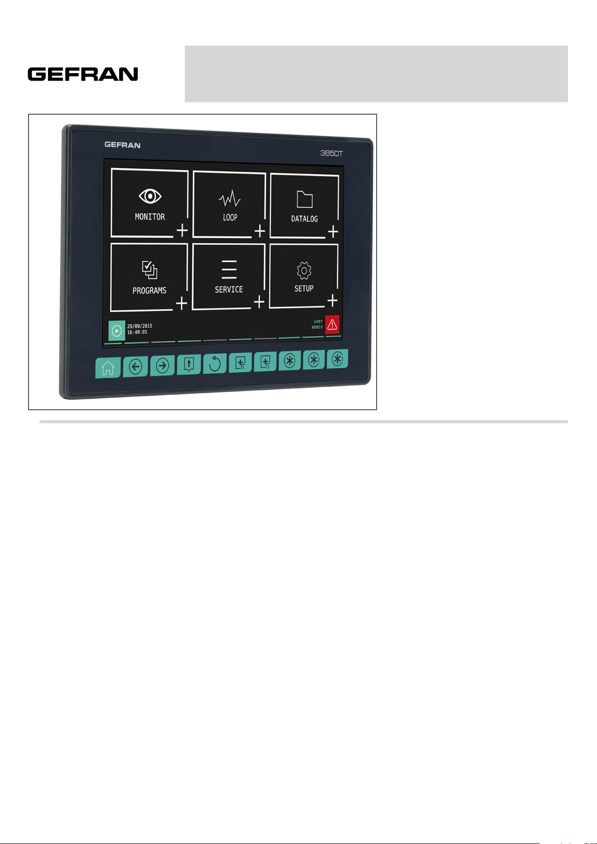
3850T
MULTIFUNCTION CONTROLLER
Main features
• Operator interface with color touch
screen display, 7”
• Up to 16 PID control loops
• Cascade, ratio and valve PID controls
• Profile programmer with ramps and retention; synchronous and asynchronous
• Up to 250 Programs with 50 segments
• 3 password protected user levels
• Energy meter (kWh)
• Configurable logic operations
• Configurable math functions
• Data Log with Real Time Clock
• Batch Report management
• Open format files (CSV) or encrypted for
DataLog and production batches
• Setting up custom pages
• Active and historical alarm management
• USB for data export and parameter
cloning
• Control parameter advanced tuning
• Configurable analogue and digital I/O
signals
• HMI/SCADA/PLC data exchange via
Ethernet Modbus TCP
• Message language selection
PROFILE
The 3850T multifunction controller is
designed to control the temperature in
production processes (heat treatment,
kiln and autoclave management, etc.)
used in different industrial sectors such as
automotive, food, metalworks, etc.
The controllers consist of three elements:
the operator interface with touch screen
display and keys, the I/O module group for
connection to plants and machinery and the
connection cable between the interface and
the module group.
The color touch screen display 7” allows
the operator to easily and quickly interact
with the controller, managing actions and
parameters.
Access to the main controller functions and
navigation between pages is made easier
thanks to its 10 function keys, some of
which are customisable.
Customized pages may be configured
directly on the display, even without a PC
or external software. This option allows
you create optimised graphic interfaces
to control the machinery used. A graphic
symbol library is provided for this purpose
(buttons, bargraph, data display, etc.) that
can be set and linked to the controller
variables. You may also import images,
such as representations of the machinery
or of the system’s operating diagram, to
be used as a background, to make control
even more intuitive for operators.
The controller can manage up to 16 PID
loops, fully configurable. Each PID can be
used as a control for a single loop, a valve
or a ratio control, it can be connected to
the profile programmer or be used as a
cascade controller.
Tuning is performed through advanced
algorithms that ensure stable and accurate
temperature control, avoiding exceeding
set limits or having unstable process
control even in critical heat or fast motion
processes.
The setpoint profile programmer allows
you to set the programs to manage heat
treatment cycles. The profile is the set of
segments that describe the setpoint curve.
You can create up to to 250 programs,
stored internally, each of which can contain
up to 50 segments.
Each program lets you set up to four setpoint
profiles. A descriptive message, 16 input
events (IN), 16 outbound events (OUT), the
setpoint value and the HBB alarm threshold
can be set for each program.
You can launch up to 8 programs
simultaneously, each of which can handle
up to 4 synchronous profiles.
The profile programmer can be set in
synchronous mode (all profiles are run with
a common time base) or asynchronous
(each profile can be run with an independent
time base). The asynchronous mode is
obtained by running different programs
simultaneously.
The available logical operators (AND, OR,
Timer, Counter etc.) allow you to create
custom logic operating sequences with
the PID, thus obtaining complete and
flexible machine control.
The available settable mathematical
functions (addition, multiplication,
division, minimum or maximum value,
algorithms, etc.) can be used associated
with process values as analog channels
and virtual channels, to manage advanced
controls, such as ratio controls or custom
mathematical formulas.
The Data Logger function, combined
with the Real Time Clock (RTC clock with
rechargeable buffer battery) stores process
data, IN/OUT signals and the status of
the alarms in an open file (.CSV format) or
encrypted file. The minimum data sampling
frequency is 1 second. Saved files can then
be exported from the controller via USB or
Ethernet network.
The batch report option lets you to
associate this data with a specific batch
produced, to be able to use them in
production and quality reports.
Page 2
A specific application for PC (Report
Utility) is available for easy management
of all data logger data and the production
batch reports which allows you to copy and
delete files via an Ethernet network between
the controller and a PC, manually by the
operator or automatically at configurable
time. The data stored on the PC can then
be displayed in graphical format or a
spreadsheet (Excel type) or exported as
CSV or PDF files.
For the quick and safe installation of
the machinery or plant, use the recipes
stored in the controller. The recipes, easily
retrievable by the operator, can be of two
types: OEM manufacturer recipes, which
contain the machine setup parameters and
production recipes, which contain single
production settings (profile program, logical
steps, math functions).
The recipes can be easily transferred
between different controllers via USB key
or Ethernet network.
Controllers offer complete diagnostics
(probe break down or incorrect connection,
total or partial load break down, control loop
faults), which helps the operator in case of
controlled machine or process faults.
All controller alarms are stored internally
and can be viewed as Active alarms and
Historical alarms. The relevant message is
displayed for each historical alarm with the
date and time of the various states (active
alarm, ACK, and alarm cleared). The ACK
parameter, settable for each alarm, ensures
that the active alarm was acknowledged by
the operator.
An internal energy counter, with
configurable offset alarm, provides energy
consumption and cost totals.
For accurate time stamps, the controller
supports the Simple Network Time Protocol
(SNTP) service, which continuously
updates the controller’s date and time from
the SNTP server connected via Ethernet
network.
The weekly clock function lets you
automatically start or stop a programmer
or a process, without the need of operator
intervention.
The clock is based on a settable weekly
calendar (day of week and time).
The display language selection lets the
operator interact with the device in the
preferred language, facilitating work.
Secure access to all controller parameters is
guaranteed by 3 preconfigured password
levels (Operator, Maintenance technician
and OEM manufacturer). In this way, each
user can only access the assigned functions
and parameters.
You can connect the controller to the factory
HMI/SCADA network by using standard
Modbus TCP (Ethernet) connectivity.
Complete controller configuration is
facilitated by use of the PC programming
tool GF_express, which proposes intuitive
Wizard pages, permitting easy construction
of customized graphic pages and advanced
logic.
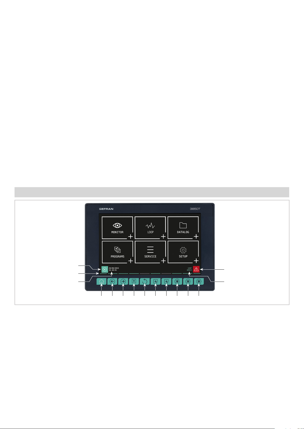
DISPLAY AND KEYS
1
2
3 14
4 5 6 7 8 9 10 11 12 13
Figure 1 - 3850T display and key description
1. Shortcut icon (the landing page depends on the option
chosen):
• Controller with PROGRAMMER option: go to the
Program Monitor page that displays main program
information and lets you manage its execution.
• Controller with RECORDER option: go to the Trend
page that displays the set variable trends in graphic
format.
2. Lighted pressed key conformation.
3. Date and time indication.
4. Home page key: return to the main menu.
5. Left Page key: changes the page in the submenus with
multiple pages.
6. Right Page key: changes page in the submenus with multiple pages.
15
7. Group Page key: go to the higher menu level.
8. Back key: return to the previous page.
9. Custom Page 1 button: go to first custom page.
10. Custom Page 2 button: go to second custom page.
11. Customizable Key Function 1: raise the digital variable
FUNCT_1.
12. Customizable Key Function 2: raise the digital variable
FUNCT_2.
13. Customizable Key Function 3: raise the digital variable
FUNCT_3.
14. Authenticated user indication. The login page opens by
touching the indication.
15. Alarm Icon: blinks to indicate an alarm; tapping the icon
opens the page that lists current alarms.
Page 3
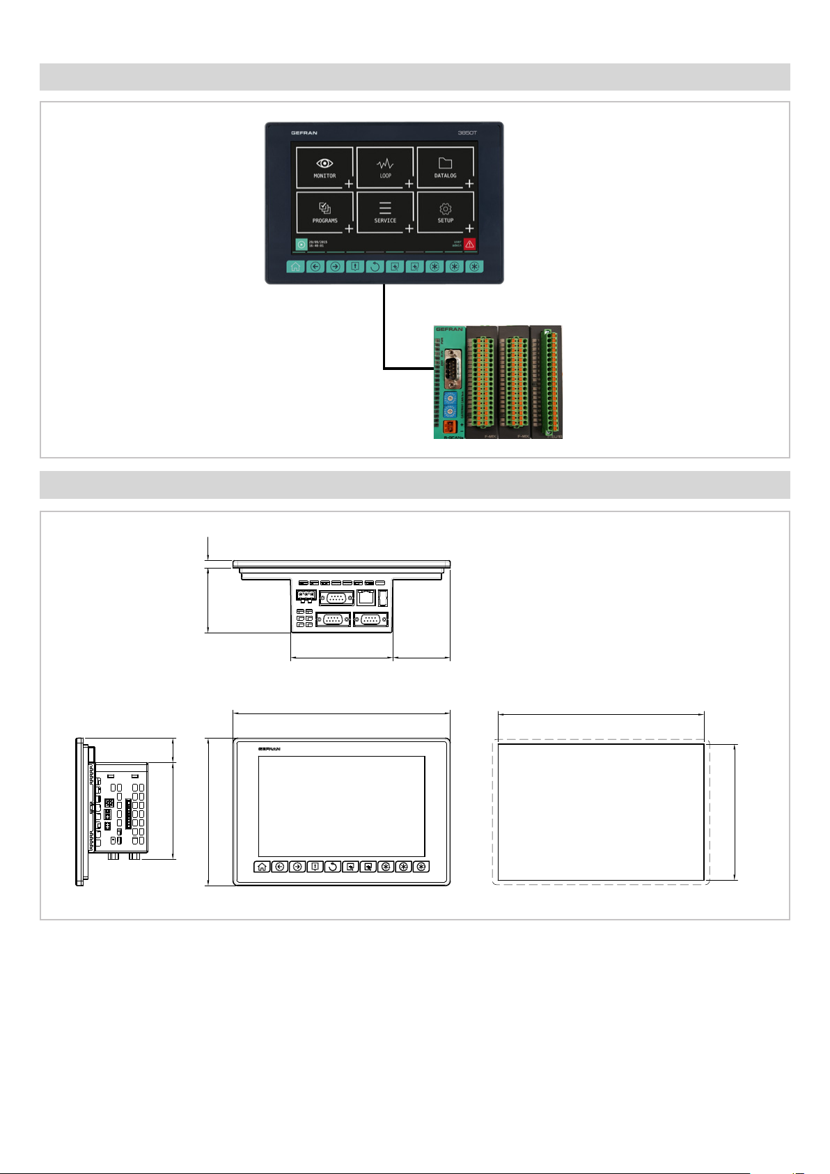
HARDWARE ARCHITECTURE
DIMENSIONS AND DRILLING TEMPLATES
59.2 6.6
22.4
88
134.4
93.3
198
52.4
3850T
187.5
Foro
124
Dimensions in mm
Page 4
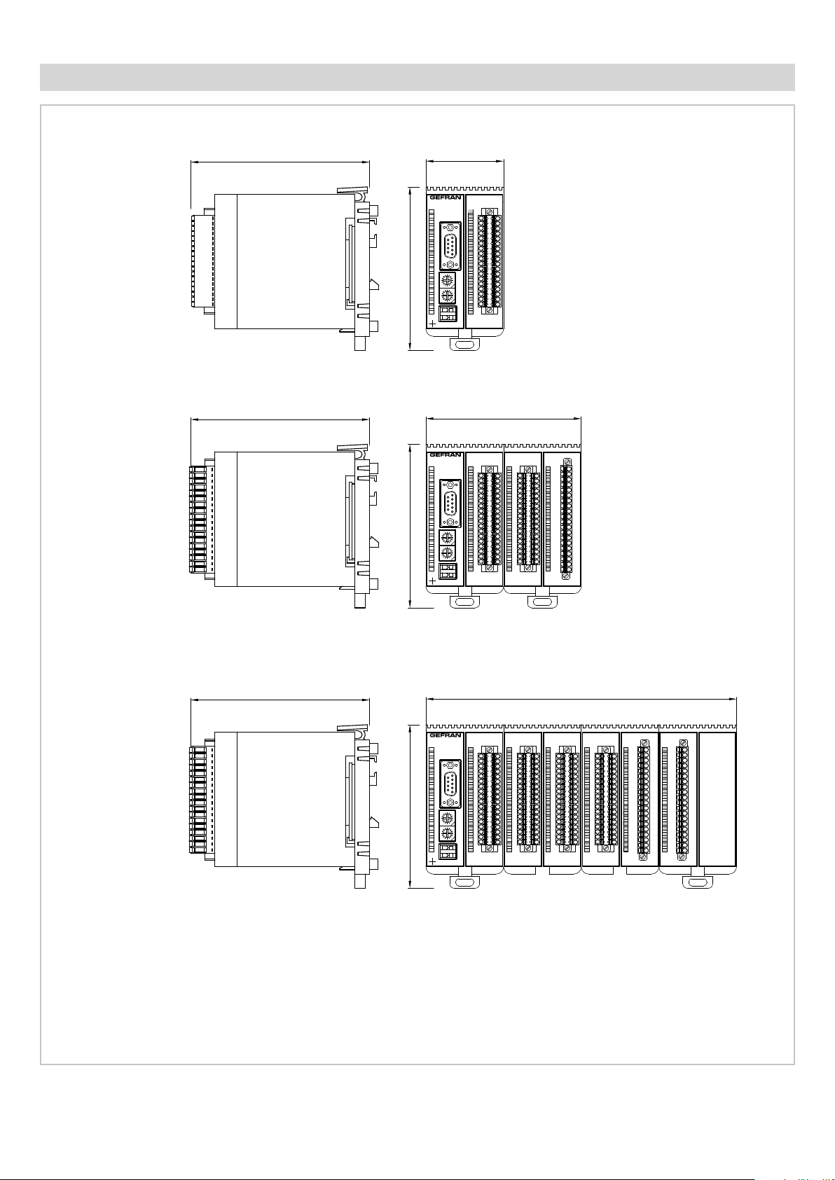
I/O MODULE DIMENSIONS
I/O 2 SLOT
I/O 4 SLOT
119,8
119,8
109,5109,5109,5
52
1
2
3
4
5
1
PWRERR RUN
6
6
7
8
9
9
5
10
11
12
C
D
B
E
13
A
F
9
0
8
14
1
1
7
2
6
3
5
4
15
C
D
B
E
A
16
F
9
0
8
131
17
7
2
6
5
4
18
GATEWAY CAN bus
19
1 2
4
20
3
F-GCANs
F-MIX
104
1
1
2
3
4
5
1
PWRERR
6
6
7
RUN
8
9
9
5
10
11
12
C
D
B
E
13
A
F
9
0
8
14
11
7
2
6
3
5
4
15
C
D
B
E
A
16
F
9
0
8
1
1
17
7
2
6
3
5
4
18
GATEWAY CAN bus
19
20
2
314
F-GCANs
F-MIX
1
2
2
3
3
4
4
5
5
6
6
7
7
8
8
9
9
10
10
11
11
12
12
13
13
14
14
15
15
16
16
17
17
18
18
19
19
20
20
F-EU16F-MIX
I/O 8 SLOT
Dimensions in mm
119,8
208
1
1
1
2
2
3
3
4
4
5
1
PWRERR
6
RUN
9
5
C
D
B
E
A
F
9
0
8
1
1
7
2
6
3
5
4
C
D
B
E
A
F
9
0
8
1
1
7
2
6
3
5
4
GATEWAY CAN bus
21
4
3
F-GCANs
5
6
6
7
7
8
8
9
9
10
10
11
11
12
12
13
13
14
14
15
15
16
16
17
17
18
18
19
19
20
20
F-MIX
F-MIX F-MIX F-EU16F-EU16F-MIX
1
2
2
3
3
4
4
5
5
6
6
7
7
8
8
9
9
10
10
11
11
12
12
13
13
14
14
15
15
16
16
17
17
18
18
19
19
20
20
1
1
2
2
3
3
4
4
5
5
6
6
7
7
8
8
9
9
10
10
11
11
12
12
13
13
14
14
15
15
16
16
17
17
18
18
19
19
20
20
Page 5
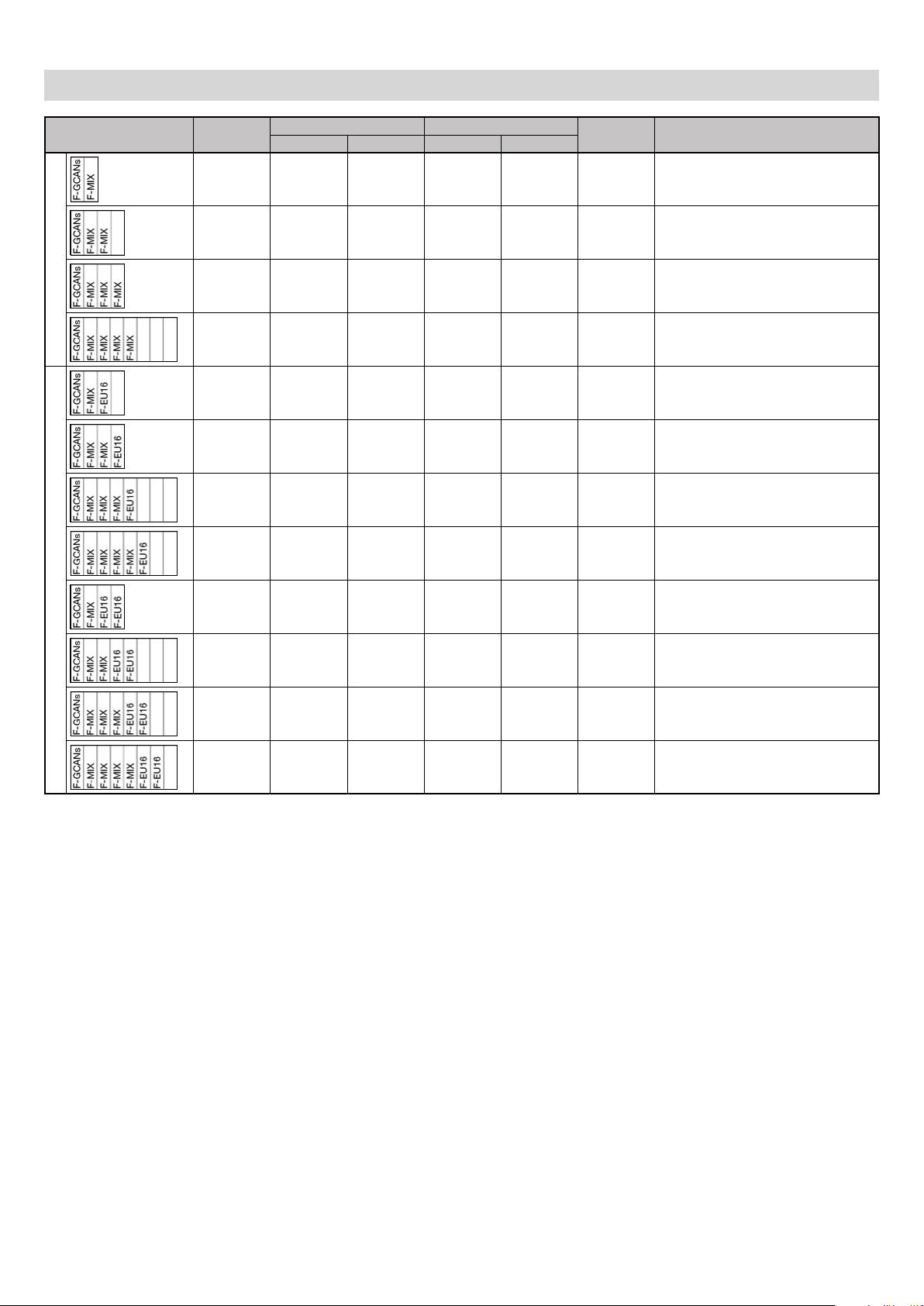
I/O MODULE COMPOSITIONS
Composition Mod.
Standard
1
2 4 2 8 8 22 3850T-xx-04-xx-xx-xx-xx-xx-00-x-x
4 8 4 16 16 44 3850T-xx-08-xx-xx-xx-xx-xx-00-x-x
4 12 6 24 24 66 3850T-xx-12-xx-xx-xx-xx-xx-00-x-x
8 16 8 32 32 88 3850T-xx-16-xx-xx-xx-xx-xx-00-x-x
4 4 2 16 16 38 3850T-xx-04-xx-xx-xx-xx-xx-08-x-x
4 8 4 24 24 60 3850T-xx-08-xx-xx-xx-xx-xx-08-x-x
8 12 6 32 32 82 3850T-xx-12-xx-xx-xx-xx-xx-08-x-x
8 16 8 40 40 104 3850T-xx-16-xx-xx-xx-xx-xx-08-x-x
Analog Digital
IN OUT IN OUT
Tot.
I/O
3850T code
4 4 2 24 24 54 3850T-xx-04-xx-xx-xx-xx-xx-16-x-x
with additional digital expansions
8 8 4 32 32 76 3850T-xx-08-xx-xx-xx-xx-xx-16-x-x
8 12 6 40 40 98 3850T-xx-12-xx-xx-xx-xx-xx-16-x-x
8 16 8 48 48 120 3850T-xx-16-xx-xx-xx-xx-xx-16-x-x
Notes
1) Container dimensions in modules
n/a = composition not available
Page 6
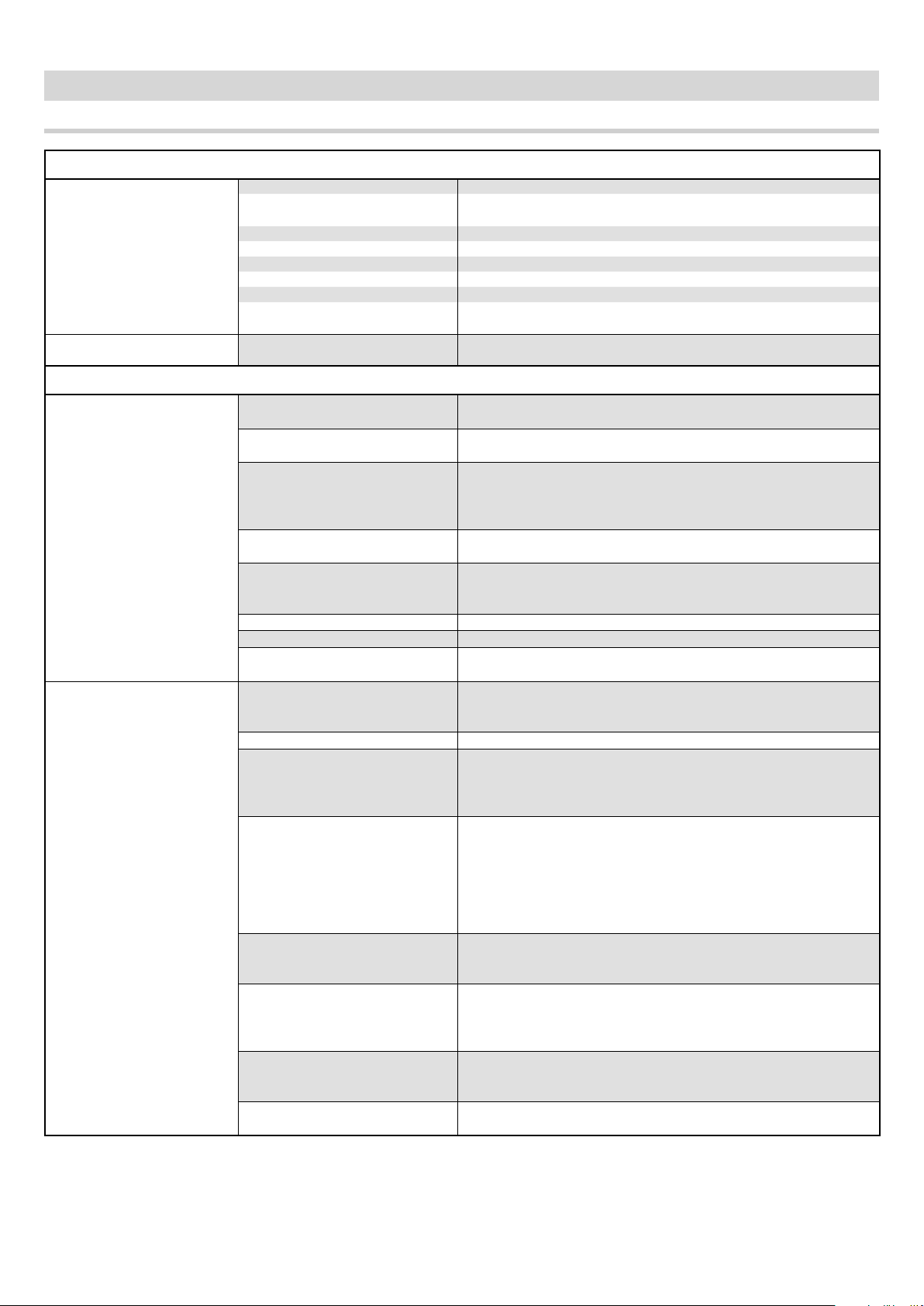
TECHNICAL SPECIFICATIONS
3850T controller
OPERATOR INTERFACE
DISPLAY
KEYBOARD
CONTROL FUNCTIONS
LOOP
(Regulation)
SETPOINT PROGRAMMER
Type TFT Touch Screen with 4-wire resistive type technology
View area
Lighting Back lit with LED, duration 50.000 hours @ 25 °C (77 °F)
Resolution (pixel) 800 × 480 (WVGA)
Colors 262,000
Max brightness 240 cd/m
Contrast 1000:1
View angle
Type
PID
Regulation type
Control output
Valve control
Sampling time 25 ms
Tuning Automatic Self Tuning algorithms.
Alarms
Programmer type
Program profile From 1 to 4 synchronous profiles
Program
Segments
IN profile events
OUT profile events
Simplified configurability
HBB alarm
Diagonal: 7”
Dimensions (L × H): 152 × 90 mm (5.98” x 3.54”)
2
Horizontal: 60°
Vertical: +45° ... -60°
Number of keys: 10 (of which 3 programmable)
Type: mechanical
Single loop; Cascade (2 consecutive PID: PID1-PID2, PID3-PID4
…); Ratio; Valve
Number: 16 max
Parameter groups: 10 max
PID
ON/OFF
Single action heat or cool
Double action heat or cool
Type: continuous (0... 100%) or ON/OFF with PWM modulation.
Cycle time: constant or optimised (Burst Firing)
Open/close for floating type motorized valve
Open/close for motorized valve with feedback (potentiometer
position control)
Number: max 4 associated with each PID
Type: maximum, minimum, symmetric, absolute/relative
Synchronous and asynchronous setpoint programs
Single-segment setpoint or ramp + maintenance profile
Integrated function blocks
Max number of programs: 250
Maximum number of programs running at the same time: 8
Available commands: START, HOLD/PAUSE, RESET, END, SKIP
Status outputs: RUN, READY,END, HOLD
Setting: time segments (dd:hh / hh:mm / mm:ss) or gradient configuration
Maximum number of segments per program: 50
Maximum number of ramps and holds per program: 100 (50 ramps - 50 holds)
High/low limit threshold configurable for each segment
PID group activation for each segment
Max number of settable IN events: 16
Acknowledged events: digital IN-resource, digital OUT, system
merker
Max number of settable OUT events: 16
ON/OFF while running the profile segment
Events acknowledged: digital OUT resource, logic operation,
programmer status
Template
Configuring and running the same program on several PIDs simultaneously
Alarm range configuration per single segment
High/low range setpoint
Page 7
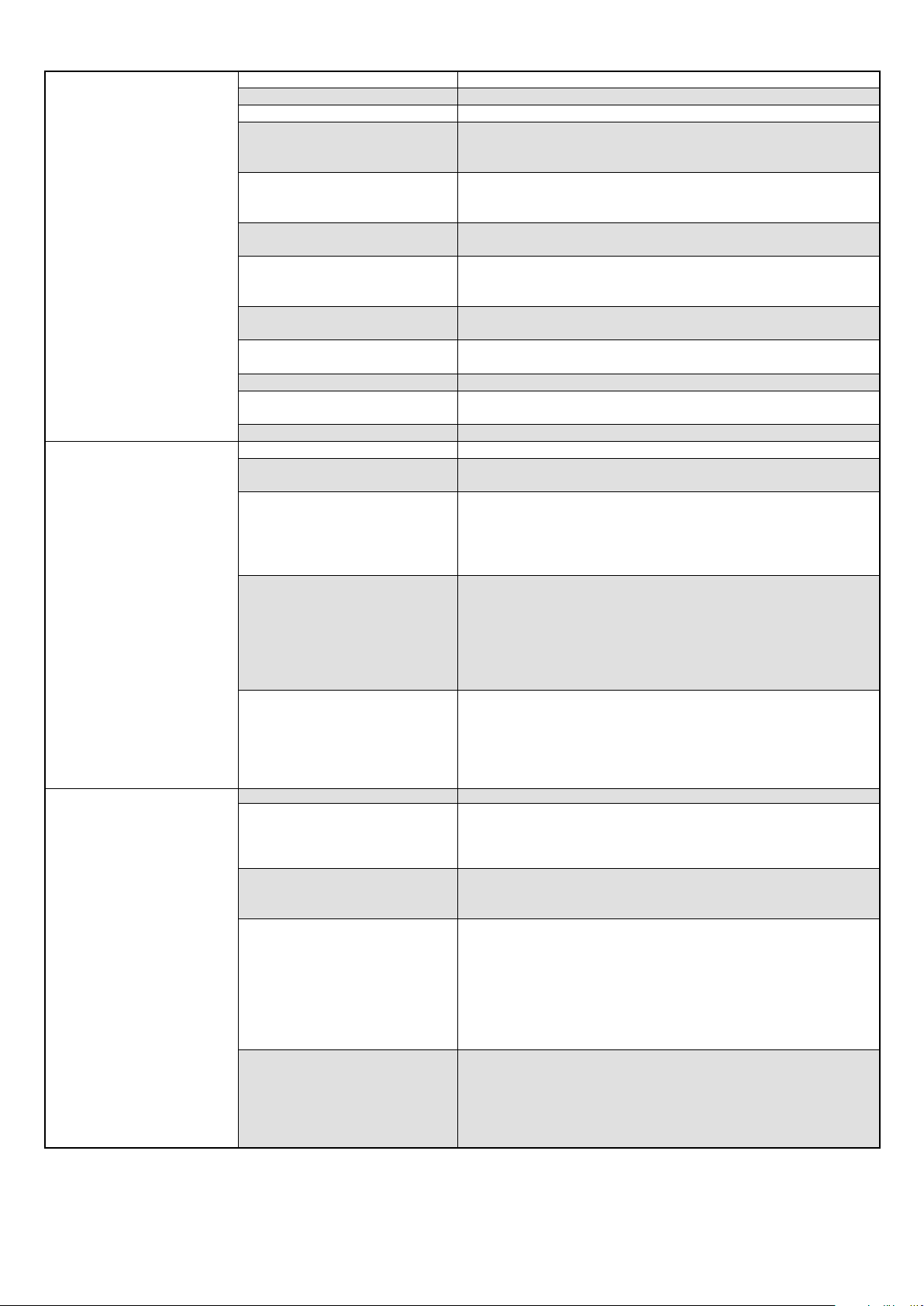
GETLogic
DATA LOGGER
PRODUCTION REPORT
(Batch report)
Scope Sequential execution of logical and mathematical instructions
Running sequences 1 for each program (max 8) + 1 global always active
Function blocks Max number per program: 200
AND, OR with default logic patterns
Logic function blocks
Timer function blocks
Counter function blocks
Basic mathematical function
blocks
Special mathematical function
blocks
Special mathematical function
blocks
Process function blocks F0 (sterilisation coefficient)
Resources for mathematics
operators
Resources for logical operators Digital In/Out, Alarm Status, System Merker
Scope Continuous configured data recording
Recordable values
Sampling
Data storage
Graphic display
Scope Synchronous recording when running the program profile
Recordable values
Sampling
Data storage
Graphic display
Set/Reset, Reset/Set
Rising edge, trailing edge
Excitation delay timer (TON)
De-energising delay timer (TOFF)
Flip/flop timer
Increasing counter
Decreasing counter
+ , - , × , : , average, minimum value, maximum value, square root,
base 10 logarithm, natural base A logarithm, and raised to the
power A, A raised to the power B
Max peak, minimum peak, hold of a value, average of 2 values,
minimum/maximum limit of a value
Selection between two values Greater/Lesser/Equal/GreaterEqual/Lesser-Equal/Different
Analog IN/OUT, SP controller, System Log/Real data
Max number of analog values: 50
Max number of digital events: 50
Sampling interval: 1 s ... 1 h
Sampling mode: single record with time information (date/time)
and values /events/actions detected
Closing the sequential log file: automatic every hour/day/week
(configurable)
File format: CSV
Data file encryption: optional
Log file name with close date/time indication
Storage media: internal memory
File export: manual via USB key or manual/automatic via Ethernet
via Gefran - DataLog Utility PC application
- Report Utility
Graph: stored log data trend
Max number of viewable curves: 8
Data selection by association: 8 curves
Single curve scaling
Available functions: enable single curve, full scale selection, zoom
+/-, scroll +/- and cursor
Max number of analog values: 50
Max number of digital events: 50
Batch name/description (selectable)
Running profile data (selectable)
Sampling interval: 1 s ... 1 h
Sampling mode: single record with time information (date/time)
and values /events/actions detected
File format: CSV
Data file encryption: optional
Log file name with close date/time indication and Job ID reference
(optional)
Storage media: internal memory
File export: manual via USB key or manual/automatic via Ethernet
via Gefran - DataLog Utility PC application
- Report Utility
Graph: stored log data trend
Max number of viewable curves: 8
Data selection by page: 8 curves
Single curve scaling
Available functions: enable single curve, full scale selection, zoom
+/-, scroll +/- and cursor
Page 8
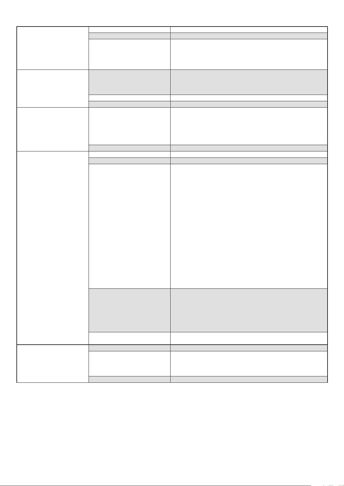
TREND GRAPH
PROGRAM RECIPE
CONFIGURATION RECIPE
GETView
WEEKLY CLOCK
Scope Continuous recording of data configured without archiving
Recordable values Max number of values: 24
Max number of viewable curves by page:8
Number of samples: 5,000
Graphic display
Data file
References Descriptive name and ID code (easy loading and activation)
Data import and export Via USB key
Types
Data import and export Via USB key
Scope Configure custom graphic pages directly from the controller panel
Number of customisable pages 10 max
Components
Available functions
Image functions
Scope Event (ON/OFF) on a weekly or daily basis
Function
Number 4 max
Single curve scaling
Available functions: enable single curve, full scale selection, zoom
+/-, scroll +/- and cursor
Programmer profile segment/event configuration
Synchronised programmer logic operations
Synchronised programmer mathematics functions
DataLog/Batch data configuration
System: number of clocks, home page, program modes ...
PID: all single PID configuration parameters
GETView: custom page configuration
InOut: analog channel range, decimal point configuration, unit of
measure configuration
Messages: custom text list
Available types:
• Led: digital variable with color/text/image change
• Notes: default text display
• Text: fixed text display
• Edit text: text view and edit
• Progress: display a value as a bar (vertical/horizontal)
• Data display: display of a numeric value
• Data edit: view and edit a numeric value
• Button: change the status of a digital value with status display (color/text/image) and change mode selection (momentary/toggle)
• System: page change function with default list selection
Maximum number of components of the same type per page:
• Text (Note, Text, Edit text) and numerical (Display date, Edit
date): max 40
• Key: max 20
• LED: max 20
• Progress: max 16
• Image: max 10
• System: max one link of each type
Add a new component
Edit component parameters
Delete a component
Move a component
Multiple component selection for move or delete
Align multiple components left
Align multiple components top
Image conversion tool from the most popular graphic file formats
Image file import and export via USB key
Configure ON/OFF event status by single day of the week
Event time settings in hh:mm
Enable the weekly clock
Enable weekly repetition
Page 9

MULTILINGUAL
DIAGNOSTICS
ALARMS
VARIABLES
USERS
REMOTE CONNECTIVITY
REPORT UTILITY
(external tool)
GF_eXpress
(PC configuration)
NON-VOLATILE MEMORY
Scope Change message language
UNICODE support
Function
Custom message translation
File import and export via USB key
Available languages Italian (ITA), English (ENG)
Scope Controller operating status
PID loop
Communication
Short circuit or probe opening
Interrupted or partially interrupted load (HB alarm)
Communication status between panel and I/O modules
Communication error alarm
I/O modules Signal status and single channel values
System Disk Full Alarm
Number 254 max
Alarm message customisation
Function
ACK/no ACK selection
Real alarm display priority order level settings
Merker (boolean)
Retain Merker (boolean)
Register (32 bit with sign)
Available types
Retain Register (32 bit with sign)
Real (32 bit)
Retain Real (32 bit)
String (text message)
Function
Number max 256 per type
Levels
Safety
Number of default levels: 3 (operator, level 0; Maintenance, level
1; OEM manufacturer, level 2)
Password
Automatic timed logout at operator level
Internal functions Add new user
Modbus TCP
VNC
Connection
Modbus TCP Slave
HMI/SCADA/DCS Data exchange systems
Remote page standard interface
Remote machine maintenance
Ethernet
Server NTP (option)
Remote DataLog and batch management
Encrypted DataLog and batch file decryption
Manual controller file copy or deletion
Function
Timer Configuration for automatic controller file copy or deletion
Data trend graphic display (with graph zoom and scroll)
Data display in spreadsheet mode
Data export in .CSV or .PDF format
Connection Ethernet
PID controller configuration read and write
Graphic display and setting of parameters useful for Programmer
Function
functions
Logic and mathematics operation settings and display
Creating custom graphic pages
Type FRAM
Capacity 32 kB retentive variables
Max number: > 10
Write
Retention: > 10 years @ 55 °C (131 °F),
12
cycles
> 55 years @ 35 °C (95 °F)
Page 10

GENERAL DATA
Operating voltage
Current absorption
Dissipated power
VOLTAGE
Protections
Connection
Type
Specifications
BUFFER BATTERY
Duration
Power reserve in the absence of
current
Ethernet (ETH)
USB
Indoor
ENVIRONMENTAL CONDI-
TIONS
Operating temperature
Storage temperature
Relative humidity
PROTECTION RATING IP 65 on the front (according to IEC 68-2-3)
Positioning
ASSEMBLY
DIMENSIONS
Installation requirements
(L × H × D)
WEIGHT 0.25 kg (0.55 lb)
EMC conformity
(electromagnetic
EC REGULATIONS
compatibility)
LV conformity (Low Voltage)
UL REGULATIONS
24 VDC ±25%
300 mA max
7.5 W max
For polarity exchange
For short circuit
Removable 3-pin polarised connector
Screw terminals, max 2,5 mm
2
(0.0038 in2 ) (13 AWG) cable section
Ml2032, not replaceable
Rechargeable Li-Al, 3 V 65 mAh
10 years.
High temperatures can reduce battery life.
> 20 months
Connector: RJ45
Speed: 10 / 100 Mbit/s
Signals: Green LED = connection, yellow LED = data transfer
Protocols: FTP (File Transfer Protocol), Modbus TCP/IP Master/
Slave
Connector: type A
Type: Host Port
Version: 2.0 Full Speed
Current: 100 mA max
File system for USB key (Flash Drive): FAT32
Use
0 ... +55 °C (32.. 131 °F) (according to IEC 68-2-14)
-20 ... +70 °C (-4.... 158 °F) (according to IEC 68-2-14)
Max 95% RH non condensing (according to IEC 68-2-3)
On panel, front pull-out
Installation category: III
Pollution rating: 2
Insulation: double
100 × 100 × 59,5 mm (3.94” x 3.94” x 2.34”) max
Compliance with the 2014/30/EU Directive
EMC Emission: EN 61000-6-4
EMC Immunity: EN 61131-2, EN 61000-4-2,
EN 61000-4-3, EN 61000-4-4, EN 61000-4-5,
EN 61000-4-6, EN 61000-4-8, EN 61000-4-11
Compliance with the 2014/35/EU Directive
LVD safety: EN 61010-1
Compliance with UL508 standard
Page 11

F-GCANs communications module
GENERAL DATA
Operating voltage 24 VDC ±25%
Current absorption 2 A max
VOLTAGE
CONNECTIONS CAN
SIGNAL ELEMENTS
ENVIRONMENTAL CONDI-
TIONS
PROTECTION RATING IP20
ASSEMBLY
DIMENSIONS (L × H × D) 25.4 × 92 × 90 mm (1” x 3.62” x 3.54”)
WEIGHT 0.15 kg (0.33 lb)
EC REGULATIONS
UL REGULATIONS Compliance with UL508 standard
Dissipated power 2.5 W
Connection
Error Red LED
Running Green LED
Voltage Yellow LED
Indoor Use
Operating temperature 0 ... +55 °C (32.... 131 °F)
Storage temperature -20 ... +70 °C (-4 .... 158 °F)
Relative humidity max 95% RH non-condensing
Positioning Vertical
Mount On DIN 35 mm (1.38”) rail
EMC conformity
(electromagnetic
compatibility)
Polarised connector with spring terminals,
cable 1 mm
Connector: DB9
Protocol: CANopen 2.0B, level CAN DS301 v.3.0, v4.0
Compliance with the 2014/30/EU Directive
EMC Emission: EN 61000-6-4
EMC Immunity: EN 61131-2, EN 61000-4-2,
EN 61000-4-3, EN 61000-4-4, EN 61000-4-5,
EN 61000-4-6, EN 61000-4-8, EN 61000-4-11
2
(0.0015 in2) (17 AWG) max
Page 12

F-MIX module
INPUTS
ANALOG
Number 4 configurable + 2 by amperometric transformer
Sensor type TC, RTD (PT100, PT1000), IR sensor, linear DC
Single-ended voltage input
Differential voltage input
Current input
Potentiometer input
Extensometer input
TC input
(thermocouple)
RTD input
(thermoresistance)
Input from a current transformer
Temperature unit of measure ° C or ° F, selectable
Probe voltage
Resolution 16 bit
Format and resolution
Voltage: 0...10 V, 0...2,5 V
Impedance: >5 MΩ (channel 1: > 50 MΩ)
Voltage: 0...60 mV
Impedance: >5 MΩ
Current: 0...20 mA, 4…20 mA
Load: 100 Ω
Potentiometer resistance: 100 Ω min.
Impedance: >5 MΩ (channel 1: > 50 MΩ)
Voltage: -5...35 mV, -10...130 mV
Impedance: > 5 MΩ
Thermocouple: J, K, R, S, T, N, C, D, E, B, L (CJ internal)
Impedance: > 5 MΩ
Number of wires) 2, 3 or 4
Thermoresistance: PT100, PT1000
rms current: 0…50 mA RMS
Frequency: 50/60 Hz
Impedance: 50 Ω
Voltage: stabilized 10 VDC or 1 VDC, selectable
Current: 130 mA max
Input type Number Min Max Resolution
Voltage 0...10 V Number
Voltage 0...2,5 V Number
Voltage 0...60 mV Number
Current 0...20 mA Number
Current 4...20 mA Number
Potentiometer Number
Extensometer
-5...35 mV
Extensometer
-10...130 mV
J thermocouple °C
K thermocouple °C
R thermocouple °C
S thermocouple °C
T thermocouple °C
N thermocouple °C
C thermocouple °C
D thermocouple °C
E thermocouple °C
B thermocouple °C
L thermocouple °C
RTD PT100 °C
RTD PT1000 °C
TA mA
Number
Number
°F
°F
°F
°F
°F
°F
°F
°F
°F
°F
°F
°F
°F
0 65535 0,15 mV
0 65535 0,04 mV
0 65535 0,9 μV
0 65535 0,3 μA
13107 65535 0,3 μA
0 65535
0 65535 0,6 μV
0 65535 2,14 μV
-210,0
-346
-270,0
-454
-50,0321768,0
-50,0
-58
-270,0
-454
-270,0
-454
0,0322300,0
0,0322300,0
-270,0
-454
44,0321800,0
-200,0
-328
-200,0
-328
-200,0
-328
0,0 50,0 0,01 mA
1200,0
2192
1372,0
2501
3182
1768,0
3214
400,0
752
1300,0
2372
4172
4523
1000,0
1832
3272
900,0
1652
850,0
1562
850,0
1562
0,1 °C
0,2 °F
0,1 °C
0,2 °F
0,1 °C
0,2 °F
0,1 °C
0,2 °F
0,1 °C
0,2 °F
0,1 °C
0,2 °F
0,1 °C
0,2 °F
0,1 °C
0,2 °F
0,1 °C
0,2 °F
0,1 °C
0,2 °F
0,1 °C
0,2 °F
0,1 °C
0,2 °F
0,1 °C
0,2 °F
Page 13

TC input (*) Note 1
Calibration: < ±(0,25% of value read in °C + 0,1 °C / 0,2 °F)
Linearisation 1,8 % of value read
Cold joint: < ±1 °C (34,7 °F) at 25 °C (77 °F)
room temperature
Cold joint compensation > 30:1 rejection at room temperature
change
RTD input
Calibration: < ±(0.15% of value read + 0.4 °C / 0,72 °F)
Accuracy
ANALOG
Conversion time 5 ms
Protection
Electric insulation Channel-bus: 2.0 kV
Diagnostics Module state: LED and software
Number 8
Voltage
Switch limit
DIGITAL
Protection
Electric insulation Channel-bus: 2.0 kV
Diagnostics
(*) Note 1 : for TC S valid with T>100°C; for TC B valid with T>200°C
Linearisation: 0.1% of value read
Thermal shift: < ±(0.005% of the value read in °C + 0.015°C /
0,072 °F) /°C starting from 25 °C (77 °F) room temperature
Linear inputs:
Calibration: < 0.1% full scale
Thermal shift: < ±0.005% full scale /°C starting from 25 °C (77 °F)
room temperature
CT input
Calibration : <0,5% full scale
Thermal shift : <+/- 0,01% full scale/°C starting from 25°C (77 °F)
Polarity inversion
Power surge: max 1 kV per 1 ms
Rated: 24 VDC (according to EN 61131-2 type 1 and type 3)
Max: 32 V, 10 mA
Low level: ≤ 8 VDC
High level: ≥ 11 VDC
Polarity inversion
Power surge: max 1 kV per 1 ms
Module state: LED and software
Channel state: LED and software
ANALOG
OUTPUTS
Number 2
Voltage output
single-ended
Current output
Resolution 16 bit
Format and resolution
Accuracy Calibration precision: ±0,1% full scale @ 25 °C (77 °F)
Conversion time 5 ms
Adjustment time 100 μs
Protection
Electric insulation
Diagnostics
±10 V, 15 mA max
0...20 mA, 4…20 mA
Max load: 600 Ω
Output type Number Min Max Resolution
±10 V Number -32768 32767 0.3 mV
0...20 mA Number 0 32767 0.6 μA
4...20 mA Number 6550 32767 0.6 μA
Short circuit: ±10 V
Overload ±10 V: 16 mA max per each channel
Open circuit 0...20 mA / 4...20 mA: Alarm status for open circuit
Power surge: max 1 kV per 1 ms
Channel-channel: No
Channel-bus: 2.0 kV
Module state: LED and software
Channel state: LED and software
Page 14

DIGITAL
GENERAL DATA
CHANNELS Number
VOLTAGE
CONNECTIONS Connector
ENVIRONMENTAL CONDI-
TIONS
PROTECTION RATING
ASSEMBLY
DIMENSIONS (L × H × D)
WEIGHT
CERTIFICATIONS
Number 8
Voltage 24 VDC ±25%
Current
Single output: 1 A max
Total outputs: 4 A max
Groups 1 group with 8 outputs
Short circuit
Protection
Overload per output @ I ≥ 2,2 A for 500 ms min.
Over temperature
Power surge: max 1 kV per 1 ms
Electric insulation Channel-bus: 2.0 kV
Diagnostics
Module state: LED and software
Channel state: LED and software
24
Operating voltage
Current absorption
Dissipated power
24 VDC ±25%
150 mA max
7.8 W
Front 36 pole
Indoor
Operating temperature
Storage temperature
Relative humidity
Wire connection with self-locking spring terminals, max cable section 0,2...1,5 mm
Use
0 ... +55 °C (32 ....131 °F)
-20 ... +70 °C (-4 ....158 °F)
max 95% RH non-condensing
2
(24...15 AWG)
IP20
Positioning
Mount
Vertical
On DIN 35 mm (1.38”) rail
25,4 × 92 × 90 mm (1” x 3.62” x 3.54”)
0.13 kg (0.29 lb)
CE, UL
If the appropriate calibration is performed in the field, the Controller meets the requirements of standard AMS2750 and may be
used in applications requiring the NADCAP directive
Page 15

F-EU16 module
INPUTS
Number 8
Voltage
Switch limit
DIGITAL
ANALOG
DIGITAL
GENERAL DATA
CHANNELS Number 16
VOLTAGE
CONNECTIONS Connector
ENVIRONMENTAL CONDI-
TIONS
PROTECTION RATING IP20
ASSEMBLY
DIMENSIONS (L × H × D) 25.4 × 92 × 90 mm (1” x 3.62” x 3.54”)
WEIGHT 0.13 kg (0.29 lb)
CERTIFICATIONS CE, UL
Filter Hardware: 100 Hz or 5 kHz selectable from software
Protection
Electric insulation Channel-bus: 2.0 kV
Diagnostics
Number 8
Groups 2 group with 4 outputs
Voltage 24 VDC ±25%
Current
Protection
Electric insulation Channel-bus: 2.0 kV
Diagnostics
Operating voltage 24 VDC ±25%
Current absorption 8 A max
Dissipated power 9 W
Indoor Use
Operating temperature 0 ... +55 °C (32 ....131 °F)
Storage temperature -20 ... +70 °C (-4 ....158 °F)
Relative humidity max 95% RH non-condensing
Positioning Vertical
Mount On DIN 35 mm (1.38”) rail
Rated: 24 VDC (according to EN 61131-2 type 1 and type 3)
Max: 32 V, 25 mA
Low level: ≤ 8 VDC
High level: ≥ 11 VDC
Polarity inversion
Power surge: max 1 kV per 1 ms
Module state: LED and software
Channel state: LED and software
Single output: 2 A max
Single group: 5 A max
Total outputs: 8 A max
Short circuit
Overload per output @ I ≥ 2,2 A for 500 ms min.
Over temperature
Power surge: max 1 kV per 1 ms
Module state: LED and software
Channel state: LED and software
Front 26 pole
Wire connection with self-locking spring terminals, max cable section 0,2...1.5 mm
2
(24...15 AWG)
Page 16
CONNECTION DIAGRAM
8
0
7
F
5
D
3
B
1
9
4
C
6
E
2
A
8
0
7
F
5
D
3
B
1
9
4
C
6
E
2
A
PWRRUNERR
+
-
GATEWAY CAN bus
F-GCANs
1 2
4 3
+
-
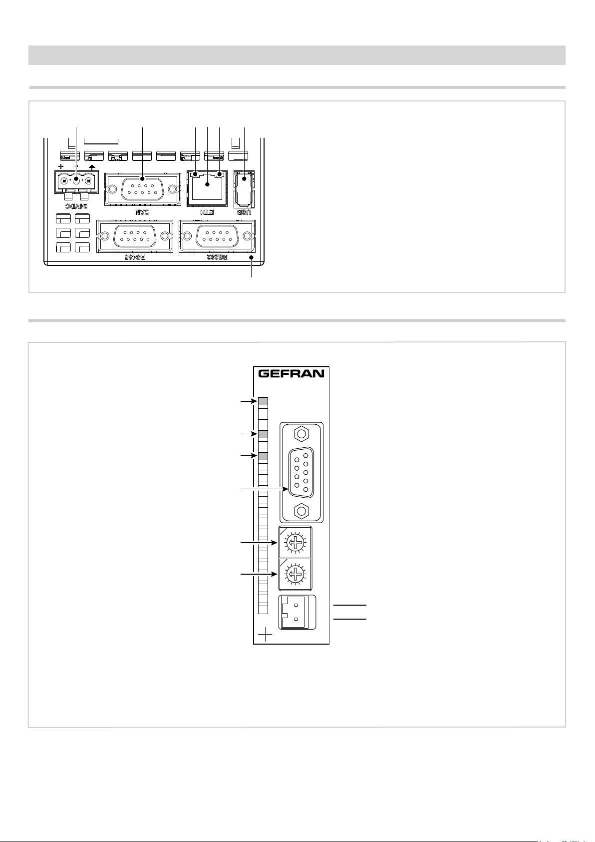
Interface connection diagram
1 2 3 4 5 6
1. Power supply 24 VDC ±25% Also connect the connector
to the ground wire.
2. CAN Port DB9 M.
3. Green LED indicates active Ethernet connection.
4. RJ45 Ethernet port 10/100 Mbit/s.
5. Yellow LED indicates data transfer in progress.
6. USB port type A.
7
F-GCANs communication module connection diagram
Yellow LED: +24 VDC power supply on
CAN bus connection
Green LED: module operating status *
*) on = module on
flashing = module not on
**) on = generic error
flashing = communication error
Red LED: module alarm **
CAN bus connector
Unused
Unused
Power supply 24 VDC ±25% 2 A max
Page 17

F-MIX module connection diagrams
General layout
Yellow LED: +24 VDC external power supply on
Green LED: digital input DI1 status ON
Green LED: digital input DI2 status ON
Green LED: digital input DI3 status ON
Green LED: digital input DI4 status ON
Green LED: digital input DI5 status ON
Green LED: digital input DI6 status ON
Green LED: digital input DI7 status ON
Green LED: digital input DI8 status ON
Green LED: digital output DO1 status ON
Green LED: digital output DO2 status ON
Green LED: digital output DO3 status ON
Green LED: digital output DO4 status ON
Green LED: digital output DO5 status ON
Green LED: digital output DO6 status ON
Green LED: digital output DO7 status ON
Green LED: digital output DO8 status ON
Green LED: module operating status *
Red LED: module alarm
A
1
2
1
3
4
5
6
7
8
9
10
11
12
13
14
15
16
17
18
35
19
20
2
1
7
Digital inputs
36
Digital outputs - Analog inputs - Analog outputs
2
8
F-MIX
+VI24
DO1
DO3
DO5
DO7
GNDI
AO1
TA1
VP1
-AI1
+AI1
AI1mA
VS1
GNDI
VP3
-AI3
+AI3
AI3mA
1
3
5
7
9
11
13
15
17
19
21
23
25
27
29
31
33
35
DI = Digital input
DO = Digital output
AI = Analog input
AO = Analog output
+VI24 = 24 V voltage
GNDI = 0 V voltage
TA = input from a current transformer
VP = Potentiometer power
VS = Extensometer input
2
4
6
8
10
12
14
16
18
20
22
24
26
28
30
32
34
36
GNDI
DO2
DO4
DO6
DO8
GNDI
AO2
TA2
VP2
-AI2
+AI2
AI2mA
VS2
GNDI
VP4
-AI4
+AI4
AI4mA
B
DI2
DI1
DI3
DI5
DI7
*) Fast flashing = module on
slow flashing = module awaiting configuration (not operating)
1
3
5
7
2
DI4
4
DI6
6
DI8
8
Page 18
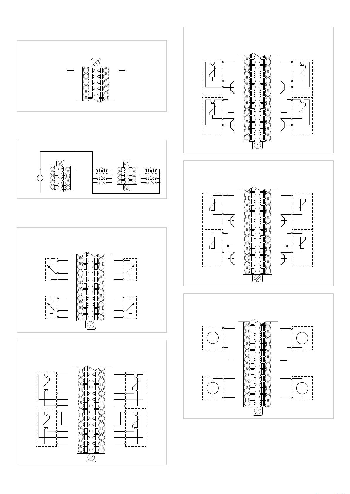
Voltage
Inputs RTD PT100/PT1000 - 3-wire connection
Voltage
+24 VDC 2
Digital inputs
Digital inputs DI1 ... DI8
A
1
3
+
24 VDC
±25%
5
-
7
9
Analog inputs
Potentiometer inputs
AI1
AI3
17
19
21
23
25
27
29
31
33
35
A
A
11
13
15
17
19
21
4
6
8
10
GND
AI1
1
3
5
7
9
23
25
AI3
27
29
31
33
35
B
DI1
2
GND
4
6
8
10
1
DI3
3
DI5
5
DI7
7
DI2
2
DI4
4
DI6
6
DI8
8
A
18
20
22
24
26
28
30
32
34
36
AI2
AI4
Inputs RTD PT100/PT1000 - 2-wire connection
A
11
13
AI1
15
17
19
21
23
25
AI3
27
29
31
33
35
Single-ended voltage inputs
A
12
14
16
18
20
22
24
26
28
30
32
34
36
12
14
16
18
20
22
24
26
28
30
32
34
36
AI2
AI4
AI2
AI4
Inputs RTD PT100/PT1000 - 4-wire connection
A
12
14
16
18
20
22
24
26
28
30
32
34
36
AI1
AI3
11
13
15
17
19
21
23
25
27
29
31
33
35
AI2
AI4
AI1
AI3
11
-
13
+
15
17
19
21
23
25
27
-
29
+
31
33
35
12
14
16
18
20
22
24
26
28
30
32
34
36
-
AI2
+
-
AI4
+
Page 19

Differential voltage inputs
Amplified current transducer inputs - 2-wire connection
A
11
13
15
17
-
AI1 AI2
+
19
21
23
25
27
29
-
AI3 AI4
+
31
33
35
Current inputs
12
14
16
18
20
22
24
26
28
30
32
34
36
-
+
-
+
A
11
13
15
-
AI1
17
19
+
21
23
25
27
-
AI3
29
31
+
33
35
Amplified current transducer inputs - 4-wire connection
12
14
16
18
20
22
24
26
28
30
32
34
36
-
+
-
+
A
AI2
AI4
AI1
+
Power supply
+
+
-
AI3
+
Power supply
+
+
-
Extensometer inputs
AI1
AI3
11
13
15
17
19
21
23
25
27
29
31
33
35
11
13
15
17
19
21
23
25
27
29
31
33
35
A
1
3
5
7
9
2
4
6
8
10
12
14
16
18
20
22
24
26
28
30
32
34
36
Power supply
+
Power supply
+
AI2
+
+
-
AI4
+
+
-
A
12
14
16
18
20
22
24
26
28
30
32
34
36
AI2
AI4
AI1
+ -
Power supply
AI3
+ -
Power supply
1
3
5
7
9
11
13
15
+
-
19
21
+
23
17
-
25
27
29
-
+
-
31
33
+
35
2
4
6
8
10
12
14
16
18
20
22
24
26
28
30
32
34
36
Power supply
-
+
-
+
Power supply
-
+
-
+
AI2
+ -
AI4
+ -
Current transformer inputs
1
9
11
max
50 mA RMS
13
15
17
A
2
10
12
14
16
18
TA2TA1
max
50 mA RMS
Page 20

Digital outputs
Analog outputs
Digital outputs DO1 ... DO8
A
2
LOAD
4
6
8
10
12
LOAD
LOAD
LOAD
DO2
DO4
DO6
DO8
GND
24 VDC
±25%
+
-
DO3
DO5
DO7
LOAD
LOAD
LOAD
LOAD
DO1
1
3
5
7
9
11
F-EU16 digital I/O module connection diagram
Yellow LED: power supply for DO1-DO4 on
Green LED: output DO1 status ON
Green LED: output DO2 status ON
Green LED: output DO3 status ON
Green LED: output DO4 status ON
Yellow LED: power supply for DO5-DO8 on
Green LED: output DO5 status ON
Green LED: output DO6 status ON
Green LED: output DO7 status ON
Green LED: output DO8 status ON
Green LED: input DI1 status ON
Green LED: input DI2 status ON
Green LED: input DI3 status ON
Green LED: input DI4 status ON
Green LED: input DI5 status ON
Green LED: input DI6 status ON
Green LED: input DI7 status ON
Green LED: input DI8 status ON
Red LED: module alarm
1
2
3
4
5
6
7
8
9
10
11
12
13
14
15
16
17
18
19
20
F-EU16
Analog outputs AO1 ... AO8
11
AO1
LOAD
+24 VDC per DO1-DO4
LOAD
LOAD
LOAD
LOAD
+24 VDC per DO5-DO8
LOAD
LOAD
LOAD
LOAD
GND
GND
13
DO1
DO2
DO3
DO4
DO5
DO6
DO7
DO8
- +
24 VDC
±25%
A
+
24 VDC
-
DI1
DI2
DI3
DI4
DI5
DI6
DI7
DI8
12
14
±25%
LOAD
AO2
Page 21

ORDER CODES
Order code:
BA E GD F H LIC
3850T - - - -- -- - - -XX XX XX XX XX XXXXXX X X
Version (A)
PID multiloop controller 0C
Recorder 0S
PID multiloop controller +
Recorder
PID multiloop controller +
Programmer + Recorder
HW configuration (B)
4 analog inputs + 2 analog
outputs + 8 digital inputs + 8
digital outputs
8 analog inputs + 4 analog
outputs + 16 digital inputs +
16 digital outputs
12 analog inputs + 6 analog
outputs + 24 digital inputs +
24 digital outputs
16 analog inputs + 8 analog
outputs + 32 digital inputs +
32 digital outputs
Reserved to Gefran (C)
Smart function (D)
No 00
SD Data Storage + SD Card
1
1 GB
CS
PS
04
08
12
16
00
01
Reserved to Gefran (L)
Reserved to Gefran (l)
I/O digital expansions (H)
No 00
8 digital inputs + 8 digital
outputs
16 digital inputs + 16 digital
outputs
Reserved to Gefran (G)
GETView (F)
No 00
Yes GV
GETLogic (E)
No 00
Yes GL
08
16
00
0
0
1) SD option includes a 1 GB SD Card
The SD option is not available for the Multiloop model (0C)
Page 22

Code examples
Digital
Common
cations
RS485 modbus RTU
Logic + mathematics functions
Ethernet modbus TCP
Custom page
Inputs Outputs
F code Model
PID loop controller
Programmer
Data Logger + Batch Reports
Analog
Digital
Analog
F072132 3850T-PS-04-00-01-GL-GV-00-00-0-0 X X X 4 8 2 8 X X X X
F071754 3850T-PS-04-00-00-GL-GV-00-00-0-0 X X X 4 8 2 8 X X X X
F067231 3850T-PS-08-00-00-GL-GV-00-00-0-0 X X X 8 16 4 16 X X X X
F072017 3850T-PS-08-00-01-GL-GV-00-00-0-0 X X X 8 16 4 16 X X X X
F072949 3850T-PS-12-00-01-GL-GV-00-08-0-0 X X X 12 24 6 24 X X X X
F073323 3850T-PS-16-00-00-GL-GV-00-00-0-0 X X X 16 32 8 32 X X X X 8 8
I/O digital
expansions
Modbus TCP + VNC remote connection
Digital inputs
Digital outputs
Page 23

ACCESSORIES
Code Description
F067612 2 m communication cable
F068066 10 m communication cable
F069369 F-MIX Module 4 AI + 2 AO + 8 DI + 8 DO
F067224 F-EU16 Module 8 DI + 8 DO
F035293 F-GCANs CANOpen communication module
F057679 USB_PEN1G 1 GB USB key
F029933 GT_USBPAN A-A USB extension with panel mount, IP65 cap and fastening screws
F057777 SD_CARD1G 1 GB SD Card
Page 24

Conformity TC RU C-IT.ГP01.B.01459
UL
Conformity C/UL/US File no. E216851
EMC (electromagnetic compatibility): conforms to directiv 2014/30/EU with reference to standard EN 61326-1
emission in industrial environment class A
Safety LVD: conforms to directiv 2014/35/EU with reference to standard EN61010-1
DTS_3850T_06-2017-ENG
 Loading...