

Page 1
1600V / 1800V
CONTROLLER for MOTORIZEDVALVES
Main applications
• Ovens
• Processing plants for chemical
and pharmaceutical industries
• Food processing plants
• Sterilizers, autoclaves,
continuous ovens and drying
unit ceramics and bricks
Main features
• Universal input configurable from the
faceplate
• Acquisition of the input signal every
120msec ; resolution 30000steps
• Two control outputs: relay, logic or
analogue with Open/Close valve
function
• 3 configurable alarms
• 2 analogue outputs (retransmission)
• 2 digital inputs with configurable
function
• Auxiliary input for valve position
potentiometer feedback
• Heater Break or shortcircuit probe
alarm
• Self and Auto-tuning, Soft-start,
Local/Remote setpoint, Auto/Man
• Multiset function, timer set ramp
GENERAL
Microprocessor controller for three-step
motorised valves, 48x96 / 96x96 (1/8DIN
- 1/4DIN) size.
Manufactured using SMT, the instrument
provides a complete operator interface,
protected by a Lexan membrane that
ensures level IP65 faceplate protection.
It has 4 keys, two green LED displays,
each with 4 digits, 4 red indicating LED’s
for the 4 logic or relay outputs, and a
further 3 LED’s that are programmable to
indicate the various operational states of
the instrument.
10 led red bargraph indication can be
associated with analogue outputs for
control, inputs, deviations or valve
position.
The main input for the process variable is
universal and provides the possibility to
connect many types of input sensor:
thermocouple, resistance thermometer,
thermistor, linear inputs, potentiometer, all
with the possibility of custom linearisation
that can be defined using the faceplate
keys.
The type of input is selected from the
faceplate keys and no external shunts or
adapter are required.
It is possible to activate correction of the
input using a linear function defined by
way of two points on it.
A second auxiliary isolated analogue
input is available, which can also be
configured for a linear input or,
potentiometer for valve position feedback.
It is possible to configure the 2 available
isolated digital inputs for selection of up
to 4 local setpoints; start, stop and reset
of internal timer; Auto/Man, Loc/Rem
functions; alarms memory reset; input
hold function.
This instrument has up to 4 relay (3A,
250V) or logic (12Vdc, 20mA) outputs, 2
of which will be dedicated to the
open/close valve functions and up to 2
isolated analogic outputs, in voltage or
current.
Every output function is configurable from
keypad; available functions are control
output (open/close valve); alarm output;
timer controlled output; digital input
repetition; retransmission of process
value, setpoint, deviation, alarm setpoint
or value read from digital communication.
A further isolated output (10 or 24Vdc,
30mA max.) is available for powering
external transmitters or potentiometers.
The serial communication interface
RS485 (RS232C compatible) makes it
possible to read or modify any parameter
and to govern the instrument online
(local/remote manual/automatic
commutation, internal timer control, direct
control of outputs).
Protocols available: MODBUS RTU and
CENCAL (Gefran).
Using these protocols it is possible to
write to any of the instrument parameters.
Specific parameters are present for the
valves control, i.e. the actuator stroke
time, the minimum pulse time, the
impulsive intervent threshold, the dead
zone; also the control type is configurable
with or without potentiometer feedback;
with PD or PID algorithm.
All the programming procedures of the
instrument are facilitated by the grouping
of the parameters in function blocks (
CFG
for the control parameters, Inp for the
inputs, Out for the outputs, etc.) and by
the possibility of selecting a simplified
menu for entering the most frequently
used parameters.
The instrument can also select the
parameters to display depending on the
hardware configuration, automatically
hiding those that are not influential.
To simplify the configuration even further,
a programming kit is available for PC,
which includes a menu driven
configuration program for Windows and
the necessary cable to connect the
instrument (see data sheet cod.
WINSTRUM).
Page 2
TECHNICAL DATA
INPUTS
Accuracy 0,2% f.s. ±1digit.
Acquisition of the input signal 120msec.
Decimal point position for linear groups
can be set freely.
For inputs from TC , RTD, PTC a decimal
figure in the maximum display field
(-199,9...999,9).
TC - Thermocouples
J (Fe-CuNi) 0...1000°C / 32...1832°F
K (NiCr-Ni) 0...1300°C / 32...2372°F
R (Pt13Rh-Pt) 0...1750°C / 32...3182°F
S (Pt10Rh-Pt) 0...1750°C / 32...3182°F
T (Cu-CuNi) -200...400°C / -328...752°F
B (Pt30Rh-Pt6Rh) 44...1800°C / 111...3272°F
E (NiCr-CuNi) -100...750°C / -148...1382°F
N (NiCrSi-NiSi) 0...1300°C / 32...2372°F
(Ni-Ni18Mo) 0...1100°C/ 32...2012°F
L-GOST (NiCr-CuNi) 0...600°C / 32...1112°F
Custom -1999...9999
RTD 3-wires
Pt100 -200...850°C / -328...1562°F
JPt100
(JIS C 1609/81) -200...600°C/
-328...1112°F
Custom -1999...9999
PTC (alternative to RTD)
-55...120°C / -67...248°F
Custom -1999...9999
DC - Linear
0...50mV; 10...50mV; 0...20mA
4...20mA; 0...10V; 2...10V
Auxiliary input
(insulation 1500V)
For Remote Setpoint:
(0...10V, 2...10V, Ri=1MΩ)
(0...20mA, 4...20mA, Ri=5Ω)
Valve position potentiometer feedback:
> 500Ω
Logic inputs
Insulation 1500V
NPN 24V/4,5mA (PNP 24V/3,6mA)
Configurable function: Man/Auto,
Loc/Rem, Alarms Reset,Hold, timer
stop/start/reset, Setpoint selection.
OUTPUTS
Outputs fully configurable for open/close
valve function, single alarm, “OR” or
“AND”, of more alarms logic input repetition
Relay
with rating: 5A/250V, cosϕ=1
(order code: R)
Logic
11Vdc, Rout=220Ω (20mA, max.6V)
(order code: D)
Analog retransmission
isolated 1500V
- Up to 2 analogue outputs for control or
retransmission (input signal, setpoint,
auxiliary input, valve position, alarm
setpoint).
- Scale range selectable from keyboard.
- Configurable output 0...10Vdc; 0/4...20mA
- Resolution 4000 steps
SERIAL LINE
Optoisolated 4-wires
Passive Current Loop configurable (1200
baud) interface, RS232 and RS422/485
(1200, 2400, 4800, 9600, 19200 baud).
Protocol: GEFRAN CENCAL or MODBUS
POWER SUPPLY
Standard: 100 to 240Vac/dc ±10%
on request: 20 to 27Vac/dc ±10%
50/60Hz; 12VAmax.
Protection by internal fuse not serviceable
by the user
TRANSMITTER SUPPLY
isolated 1500V
10/24Vdc max. 30mA, short circuit
protection
AMBIENT CONDITION
Working temperature range: 0...50°C
Storage temperature range: -20...70°C
Humidity: 20...85%Ur non condensing
Control
P, PD or PID for motorised valve (with or
without potentiometer feedback), for
heating/cooling with parameters
configurable from the faceplate.
• Proportional band 0,0...999,9% f.s.
• Integral time 0,0...99,99 min
• Derivative time 0,0...99,99 min
• Max and min control output power
limitation 0,0...100,0%
• Manual reset -999...999 digit
• Power reset -100,0...100,0%
• Cycle time 0,1...200sec
• Minimum pulse time / Actuator stroke
time 0,0...25,0%
• Pulsating control band in percentage of
actuator stroke time 0,0...1000,0%
• Dead band (symmetrical around control
Setpoint), settable in percentage of f.s.
0,0...25,0% f.s.
Alarms
- Up to 3 alarms, settable as absolute,
deviation or symmetrical deviation alarm
with respect to the control setpoint with
configurable function (Hi or Lo).
- The alarm point may be set anywhere
within the configured scale.
- Heater Break Alarm
- Loop Break Alarm
- Alarm Hysteresis configurable
- Alarms can be assigned to main input,
auxiliary input or control SP.
WEIGHT
400g (1600V); 600g (1800V) max
complete version
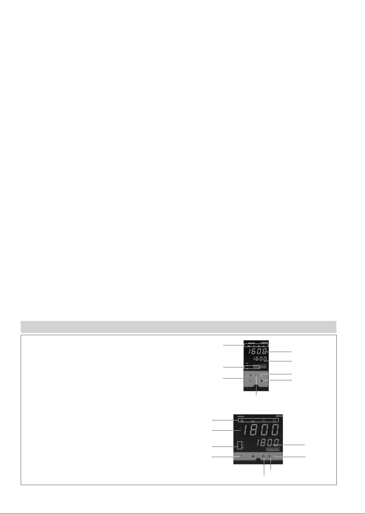
A - PV Display: process variable
B - SV Display: setpoint value
C - “Function” key
D - “Lower” key
E - “Raise” key
F - “Automatic/Manual” selection
G - Function indication
H - Indication of active outputs
Double green LED display (4 Digit)
Faceplate protection IP65
FACEPLATE DESCRIPTION
F
E
D
C
G
H
B
A
F
G
A
H
B
E
D
C
Page 3

DIMENSIONS AND CUT OUT
CONNECTION DIAGRAM
!
Apply users’ manual warnings for a correct installation
Dimensions: 48x96mm - 96x96mm (1/8DIN - 1/4DIN) depth 113mm
NC
C
NO
NC
C
NO
NC
C
NO
GND
IN2
IN1
COM
AUXILIARY
INPUT
TRANSMITTER
SUPPLY
OUT 4
(AL2)
OUT W
SERIAL
LINE
OUT 3
(AL1)
OUT 2
(CLOSE)
OUT 1
(OPEN)
PWR
SUPPLY
TC
Pt100
3-wires
PTC
Pt100
2-wires
LIN INP
Idc (20mA)
LIN INP
Vdc
96
115
108
96
113
10
92
92
115
48
70
115
44,5
92
113
10
108
96
+ Vt
Page 4

DTS_1600/1800V_0409_ENG
ORDER CODE
GEFRAN spa reserves the right to make any kind of design or functional modification at any moment without prior notice.
The instrument conforms to the European Directives 2004/108/CE and 2006/95/CE with reference to the generic standards:
EN 61000-6-2 (immunity in industrial environment) EN 61000-6-3 (emission in residential environment) - EN 61010-1 (safety)
Conformity C/UL/US File no. E216851
C - TICK
IN TA (50mAac)36
IN SPR (0/4...20mA)35
Out1 (R) + Out2 (R) + Out3 (R) + Out4 (D) RRRD
Out1 (D) + Out2 (R) + Out3 (R) + Out4 (D) DRRD
Out1 (D) + Out2 (R) + Out3 (R)
Out1 (D) + Out2 (R) + Out3 (R) + Out4 (R)
DRR0
DRRR
Out1 (R) + Out2 (R) + Out3 (R) + Out4(R) RRRR
OUT 5 (W1) 0...10V
OUT 6 (W2) 0...10V
VV
OUT 5 (W1) 0/4...20mA
OUT 6 (W2) 0...10V
IV
None 00
OUT 5 (W1) 0...10V V0
OUT 5 (W1) 0/4...20mA I0
OUT 5 (W1) 0/4...20mA
OUT 6 (W2) 0/4...20mA
II
13
IN1, IN2 NPN/PNP
IN TA(50mAc.a.) + Trasmitter Supply 10V/24V
12
IN1, IN2 NPN/PNP
IN SPR (0/4…20mA) + Trasmitter Supply 10
V/24V
11
IN1, IN2 NPN/PNP
IN SPR (0…10V) / IN Potentiometer #
+ Trasmitter Supply 10 V/24V
Out1 (R) + Out2 (R) + Out3 (R) RRR0
POWER SUPPLY
20...27Vac/dc0
100...240Vac/dc1
DIGITAL COMMUNICATIONS
None0
RS 485 / RS 2322
AUXILIARY INPUTS INSPR/INTA
DIGITAL INPUTS IN1, IN2
TRANSMITTER SUPPLY
None
IN1, IN2 NPN/PNP
00
01
Trasmitter Supply 10 V/24V
03
IN1, IN2 NPN/ PNP + Trasmitter Supply 10 V/24V
04
OUTPUTS 1,2,3,4 (R/D)
# Potentiometer input requires 10V supply transmitter
Make specific calibration request for PTC input.
Kindly contact GEFRAN for information on available codes.
10
IN1, IN2 NPN/PNP
IN SPR (0…10V) + Trasmitter Supply 10V/24V
IN SPR (0…1V) + Trasmitter Supply 10 V/24V
IN SPR (0…10V) / IN Potentiometer #
+ Trasmitter Supply 10 V/24V
06
07
IN SPR (0/4…20mA) + Trasmitter Supply 10 V/24V
08
IN TA(5050mAac) + Trasmitter Supply 10 V/24V
09
OUTPUTS 5, 6
MODEL
1600V
1800V
1600V
1800V
IN SPR (0...1V)33
IN SPR (0...10V) / Potentiometer
#
34
 Loading...