

Page 1
Dimensions
96 × 96 × 80 mm (1/4 DIN)
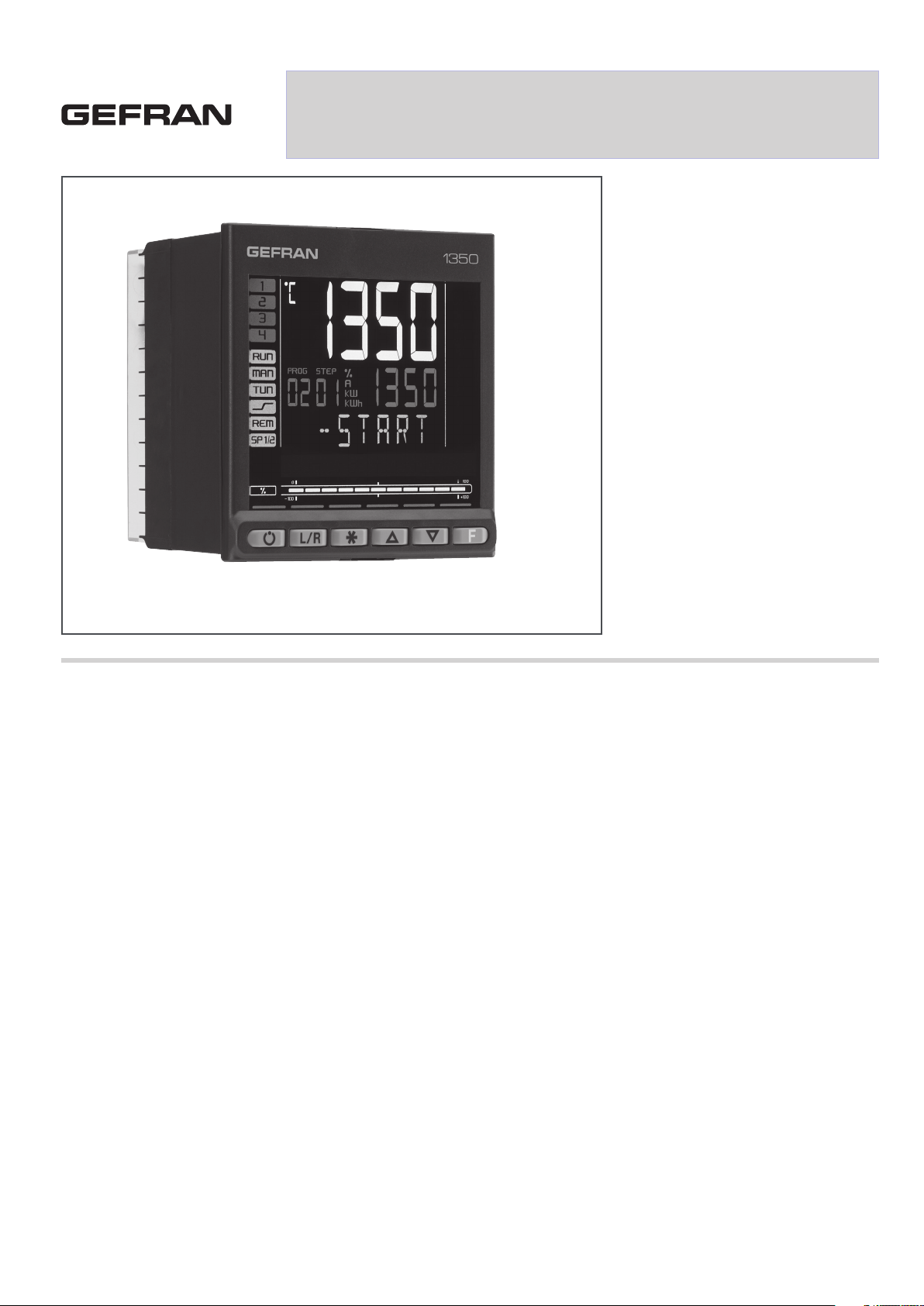
1350
PID 1/4 DIN PID TEMPERATURE CONTROLLER
Main features
• Operator interface with large LCD
Display, customizable, with choice of
colors
• Scrolling diagnostics messages,
congurable, in the selected language
• Easy, guided conguration, copy/
paste parameters even with power off
• Preventive maintenance with energy
counters (kWh) and load switching
• 16 function block applications
• Timer, setpoint and algorithm programmer
for controlling motorized valves
• Advanced tuning of control parameters
• Different password levels
• Universal input configurable for
thermocouples, resistance thermometers,
linear inputs
• Remote setpoint input
• Relay, logic, isolated analog outputs
• Up to two CT inputs for interrupted load
diagnostics
• RS485 serial communication in Modbus
RTU
• Removable faceplate for immediate
replacement
• Sampling time 60 ms
PROFILE
Operator interface
Large LCD display with customization of
colors assigned to PV, SV and F display, of
color of plastic faceplate, and of logo.
Graphic display of power, output current or
valve position. Scrolling alphameric display
of 25 messages (32 letters each), completely configurable and savable, in three languages. Thanks to language selection and
clear scrolling messages for diagnostics,
alarms, and process state, the controller
speaks the user’s language.
Easy Configuration
Guided configuration for manual-free programming, with a few essential parameters
and on-line help messages.
Ability to clone configuration among controllers, even with power off and in the
field, thanks to a mini portable configurator
with Zapper battery.
Extended configuration, creation of work
recipes, and firmware updates via PC and
GF_eXpress software, even without powering the controllers.
Thanks to the Smart Configurator function,
you obtain the required parameter recipe
by answering a few simple questions.
Local configuration and operation with
only four keys assigned to LEDs that serve as feedback for the pressed key and as
guide to specify appropriate steps.
The initial parameters can always be reset,
both from the keypad and from the GF_eXpress Software tool.
Diagnostics, Preventive Maintenance,
and Energy Monitor
Complete diagnostics for broken or incorrectly connected probe, total or partial load
break, out of range variables, and control
loop faults.
Thanks to the switching count and to the
settable alarm thresholds, you can program preventive maintenance to replace
worn actuators.
An internal energy counter with alarm for
abnormal variations totalizes energy consumptions and costs for constant control
Function block applications
Sixteen AND, OR, Timer Function Blocks let
you create customizable logic sequences
for complete and flexible machine control.
The controller’s hardware resources are
exploited completely, without any need for
external devices such as timers and small
PLCs
Tuning
Advanced tuning algorithms ensure stable
and accurate control even with critical or
very rapid thermal systems, engaging automatically when necessary.
Timer
Three types of timers let you set delay times before activating the control, hold times on the setpoint value, and timed changes of programmed setpoints.
Setpoint Programmer
Models with twelve ramp and hold steps,
groupable in four programs, with enable
inputs and event outputs, are available for
applications with setpoint profiles.
The operator interface provides two additional display dedicated to the permanent
display for: Nr. of step and Nr. program.
On-board configuration and graphic configuration with GF_eXpress.
Valve Positioner
Models to control motorized valves, without feedback.
Valve position is calculated and shown on
the display.
General characteristics
The controller is completely software configurable without accessing the internal
electronics.
The universal main input accepts thermocouple sensors, resistance thermometers,
and linears.
The controller can be replaced at any time
simply by removing the faceplate, without
any additional procedures.
Page 2
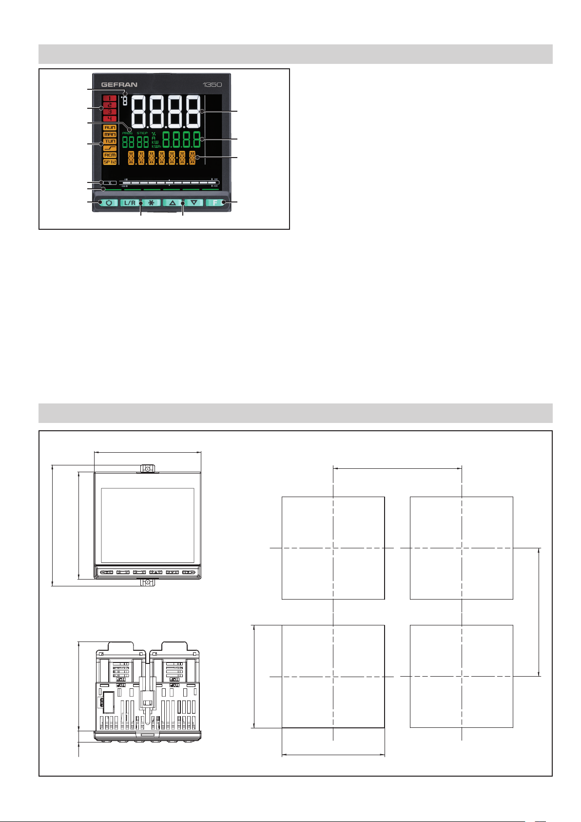
DISPLAY AND KEYS
0.39
1
2
13
3
4
12
11
10
9
5
8
6 7
1. Temperature unit of measurement or number of program
running.
2. State of outputs OUT1, OU2, OUT3, OUT4.
3. Displays program number, step number, unit of measurement (%, A, kW, kWh).
4. Controller function states:
• RUN = setpoint programmer active;
• _/- = setpoint ramp active;
• TUN = PID parameters tuning active;
• MAN = manual/automatic (off = automatic control,
on = manual control);
• REM = remote setpoint enabled;
• SP1/2 = setpoint active (off = setpoint 1,
on = setpoint 2).
5. Work mode key (manual/automatic) in standard mode.
A function can be assigned via parameter but1.
The key is active only when the display shows the process
variable.
6. Key function configurable with parameters but2 and but3.
The keys are active only when the display shows the pro-
cess variable.
7. Up/down keys: raise/lower the value of the parameter displayed on the SV or PV display.
8. F key: lets you navigate among controller menus and parameters. Confirms the parameter value and selects the next
parameter.
9. Key pressed signals.
10. Displays percentage of power or current, configurable with
parameter bArG.
11. Display F: parameters, diagnostics and alarm messages.
Configurable with parameter dS.F (default = setpoint).
12. SV display: parameter values. Configurable with parameter
dS.SP (default = setpoint).
13. PV display: process variable.
DIMENSIONS AND DRILLING TEMPLATE
96 mm
3.78 in
4.28 in
96 mm
80 mm
3.78 in
3.15 in
108.6 mm
+ 0.8
- 0.0
92 mm
115 mm
4.53 in
4.53 in
115 mm
3.64 in
10 mm
in
+ 0.8
92 mm
- 0.0
3.64 in
Page 3
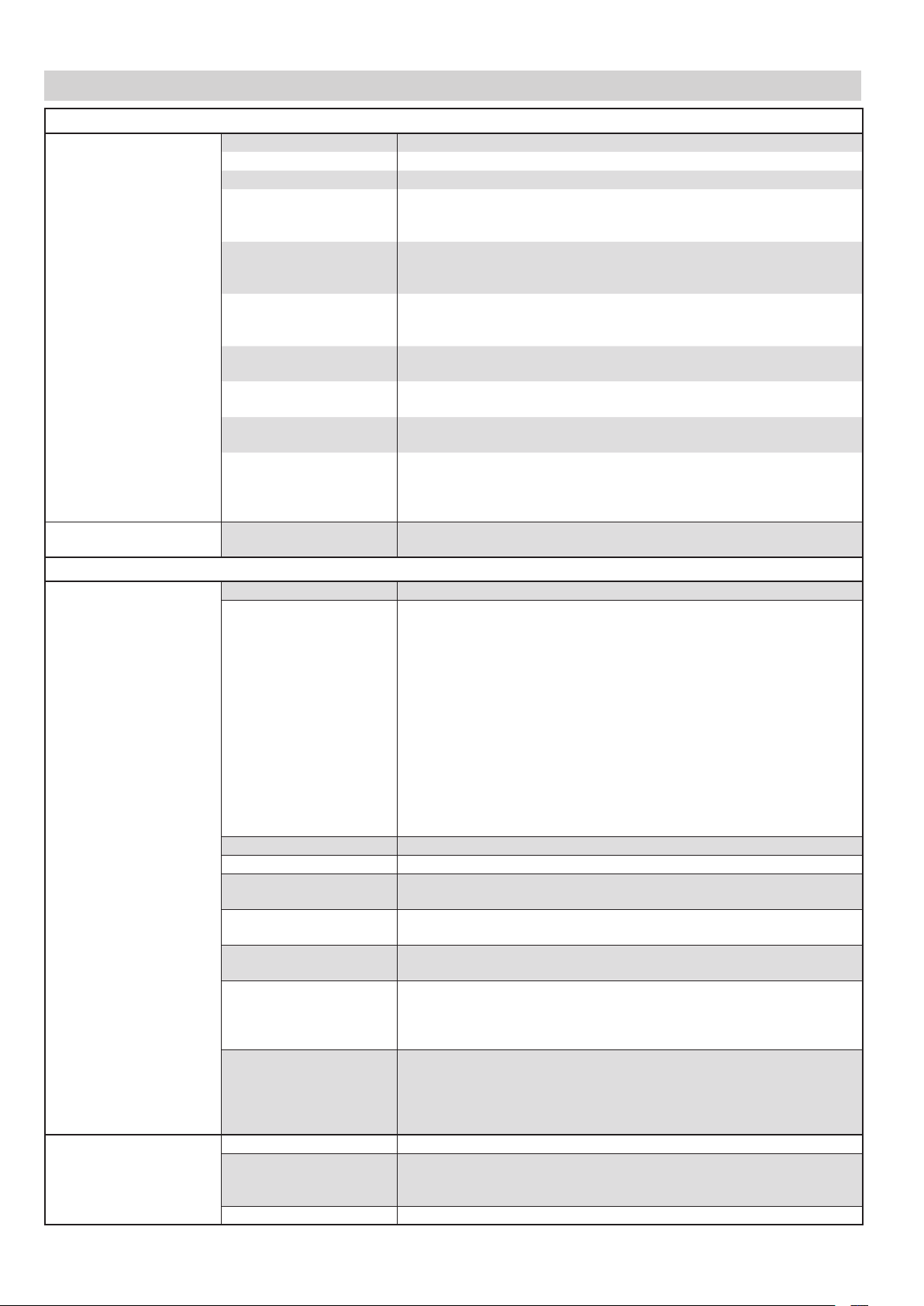
TECHNICAL DATA
OPERATOR INTERFACE
DISPLAY
KEYPAD
INPUTS
MAIN INPUT
AUXILIARY INPUT
Type LCD black background
Screen area (L x H) 83 × 68 mm
Lighting Backlit with LEDs, life > 40,000 hours @ 25°C
PV display Number of digits: 4 to 7 segments, with decimal point
Digit height: 23 mm
Color: white or “custom”
SV display Number of digits: 4 to 7 segments, with decimal point
Digit height: 11 mm
Color: green or “custom”
F display Number of digits: 7 to 14 segments, with decimal point
Digit height: 9 mm
Color: amber or “custom”
Unit of measurement Selectable, °C, °F or custom 1
Color: same as PV display
Controller state signals Number: 6 (RUN, MAN, _/-, REM, SP1/2)
Color: amber
Output state signals Number: 4 (1, 2, 3, 4)
Color: red
Bargraph indicator, configurable
Sensor type TC, RTD (PT100, JPT100), IR ES1B, DC linear sensor
Accuracy TC inputs:
Sampling time 60 ms / 120 ms, selectable
Digital filter 0,0...20,0 s
Temperature unit of measu-
rement
Signal interval Type: linear
TC
(thermocouple) input
RTD
(resistance thermometer)
input
DC linear input 0...60 mV input impedance (Ri): > 70 kΩ
Remote setpoint 0...1 V, 0...10 V, 0/4...20 mA
Scale 0...1 V input impedance (Ri): > 15 kΩ
Accuracy 0,1% f.s. ±1 digit @25 °C
Type: graphic bargraph,11 segments
Power indication: 0...100% or -100...100%
Current indication: 0...100% f.s.
Valve position indication: 0...100%
Keys number: 6, silicone ( Man/Auto, INC,DEC,F)
Type: mechanical
Calibration accuracy: < +/- (0,25% of reading value in °C +0,1°C)
Linearization accuracy: 0,1% of reading value
Cold junction accuracy: < +/- 1,5°C a 25°C room temperature)
Cold junction compensation: > 30:1 rejection to the change of the room
temperature
RTD input:
Calibration accuracy: < +/- (0,15% of reading value in °C +0,4°C)
Temperature drift: < +/- (0,005% of reading value in °C +0,015°C )/°C from
25°C room temperature
Linearization accuracy: 0,1% of reading value
Linear inputs:
Calibration accuracy:< 0,1% full scale
Temperature drift: < +/- 0,005% full scale /°C at 25°C room temperature
Degrees C / F, selectable from keypad
Scale: -1999...9999, settable decimal point
Thermocouple: J, K, R, S, T, C, D
Linearization: ITS90 or custom
Resistance thermometer: PT100, JPT100
Input impedance (Ri): ≥ 30 kΩ
Linearization: DIN 43760 or custom
Max. line resistance: 20 Ω
0...1 V input impedance (Ri): > 15 kΩ
0...5 V / 0...10 V input impedance (Ri): > 30 kΩ
0/4...20 mA input impedance (Ri): 50 Ω
Linearization: linear or custom
0...10 V input impedance (Ri): > 30 kΩ
0/4...20 mA input impedance (Ri): 50 Ω
Page 4

Type Isolated via external transformer
Number: 2 max
CT (ammeter) input
Max. capacity: x / 50 mA AC
Line frequency: 50/60 Hz
Input impedance (Ri): 10 Ω
Accuracy ±2% f.s. ±1 digit @25 °C
Type voltage-free contact, or
NPN 24 V - 4,5 mA, or
DIGITAL INPUTS
PNP 12/24 V - max 3,6 mA
(for detail see electrical connections)
Isolation 500 V
Number 5 max
OUTPUTS
ALARMS
Relay
(R)
Logic
(D)
Triac ( long life relè)
(T)
Continuous
(C)
Analog retransmission
(A1)
Number of alarm functions 4 max, assignable to an output
Possible configurations Maximum, minimum, symmetric, absolute/relative, exclusion at firing, me-
Number: 4 max
Type of relay contact: NO
Max. current: 5 A, 250 VAC / 30 VDC, cosφ = 1
Minimum load: 5 V, 10 mA
Life cycle: > 100.000 operations
Double isolation
Number: 2 max
Type: for solid-state relays
Voltage: 24 V ±10% (min 10 V @20 mA)
Isolated from main input
Number: 1 max
Load: resistive
Voltage: 12...240 VAC
Current max: 2 A
Isolation 2,5 kV
zero crossing switching
Number: 1 max
Current: 4...20mA
< 500 Ω
R
out
Resolution: 12 bit
Isolated from main input
Number: 1 max
0...10 V, max 20 mA, R
0...20 mA, 4...20 mA, R
Resolution: 12 bit
Isolated from main input
mory, reset from keypad and/or contact, LBA, HB
HBB Hold Back Band if enabled with Programmer function
CONTROL FUNCTIONS
Type Single loop
Control PID, ON/OFF, single action heat or cool, double action heat/cool
CONTROL
SETPOINT
PROGRAMMER
MULTIPLE
SETPOINTS
LOGIC
1
OPERATIONS
1) Programming is done with the GF_eXpress configuration program.
Control output Continuous or ON/OFF
Cycle time: constant or optimized (BF)
Control output for motori-
zed valves
OPEN/CLOSE for floating motorized valve on Relay, Solid-state, Triac
outputs
Number of programs Max 4
Start / Stop / Reset / Skip via digital inputs and/or outputs from logic
operations
Output state: Run /Hold / Ready / End
Number of steps Max 12, each with own setpoint, ramp time and hold time
Times settable in HH:MM or MM:SS
Max 4 consents, configurable for ramp and for hold
Max 4 events, configurable in ramp and in hold
Number of setpoints Max 4, selectable from digital input
Each setpoint change is subject to set ramp, different for up and down
ramp
Function blocks Max 16, with 4 input variables per block.
The result can act on the state of the controller, of the programmer on
alarms and outputs.
Each function contains an incorporated timer block timer.
: > 500 Ω
out
: < 500 Ω
out
Page 5

TIMER FUNCTION
ENERGY COUNTER
DIAGNOSTIC
RETENTIVE MEMORY
SERIAL INTERFACE
GENERAL DATA
POWER SUPPLY
CONNECTIONS
AMBIENT
CONDITIONS
PROTECTION LEVEL
ASSEMBLY
DIMENSIONS
WEIGHT
CE STANDARDS
Modes START / STOP
STABILIZATION (timer is on when PV enters a band set around setpoint;
at end of count you can activate an output, shut down SW or change
SP1/SP2)
FIRING (timed activation of control after power on)
Calculation done on nominal line voltage and nominal load power or on
rms current measured on load via CT
Short circuit or open circuit (LBA alarm)
Interrupted or partially interrupted load (HB alarm)
Short circuit of control output (SSR alarm)
Type EEPROM
Max. number of writes 1.000.000
Type RS485
Baudrate 1200, 2400, 4800, 9600, 19.200, 38.400, 57.600, 115.200 bit/s
Protocoll MODBUS RTU
Isolated from main input
Operating voltage 100...240 VAC/VDC ±10%, 50/60 Hz
(on request 20...27 VAC/VDC ±10%)
Power dissipation 10 W max
Protections Overvoltage 300 V / 35 V
Connection Screw terminals and crimp connector, max. wire section 1 mm
Serial configuration port
Connector: microUSB
2
(for USB connection)
Inputs and outputs Screw terminals and crimp connector, max. wire section 2,5 mm
2
Use Indoor
Altitudine 2000 m max
Operating temperature -10 ... +55 °C (as per IEC 68-2-14)
Storage temperature -20 ... +70 °C (as per IEC 68-2-14)
Relative humidity 20...85% RH non-condensing (as per IEC 68-2-3)
IP 65 on front panel (as per IEC 68-2-3)
Positioning On panel, removable faceplate
Installation regulations Installation category: II; Pollution degree: 2
Isolation: double
96 X 96 mm (1/4 DIN)
Depth: 80 mm
0,24 kg
EMC
(electromagnetic compa-
Conforms to directiv 2014/30/EU with reference to standard EN 61326-1
emission in industrial environment class A
tibility)
Safety: LVD Conforms to directiv 2014/35/EU with reference to standard EN61010-1
ACCESSORIES
Code Description
F060800 Cable for programming with PC, USB-TTL 3 V with USB – microUSB connectors, length 1.8 m
F043958 “GF_eXpress” software CD
F060909 Configuration kit for new instruments GF_eXK-3-0-0
F060908 Portable configurator, complete with cable and Zapper
51970 Rubber gasket 96×96 front box
51069 Rubber gasket 99×96 box-panel
49030 Fastening box to panel
51328 Protection of contacts at box bottom
51738 36 contacts at box bottom
330200 Current transformer (CT) 50/0.05 A
330201 Current transformer (CT) 25/0.05 A
Page 6

CONNECTION DIAGRAM
OUT 4
IN 5
IN 4
IN 3
IN 2
IN 1
COM
C
37
~
~
NO
A (Data +)
B (Data -)
36
38
35
39
34
40
33
41
32
42
31
30
43
29
44
28
45
27
46
26
47
25
48
~
12
PWR
11
~
C
10
+
C
-
OUT 3
OUT 2
OUT 1 (main)
TT
5 V, 10 V
+
-
+
-
9
NO
C
8
7
6
5
4
3
2
1
NO
NO
+
-
C
+
-
+
-
LEGEND
~
Power supply
PWR
~
+
Linear input in
voltage/current
-
Input for current
transformer
SPR +
Remote Set-point
SPR -
CT1
CT2
+
-
SPR +
SPR -
+
-
T
A1
36
35
34
33
32
31
30
29
28
27
26
25
Isolated digital
inputs
Thermocouple
input
Input
PT100
T
JPT100
2 / 3 wires
C
NO
~
~
+
-
+
-
C
NO
Long-life solid state relay
output
Isolated analog output
A1
Logic output
Relay output
A (Data +)
B (Data -)
RS485 serial line
ATTENTION: For correct installation, read the warnings in the instruction manual.
!
Page 7

ORDER METHODS
Ordering code
Model
Controller Programmer P
Valve V
Output 1
Relay R
Static D
Analog 4...20mA C
Output 2 - 3 - 4
1 Relay (5A) R-0-0
1 Static D-0-0
2 Relay (5A) R-R-0
1 Static +1 relay (5A) D-R-0
2 Relay (5A) + 1 Long Life relay R-R-T
1 Static + 1 relè (5A)+ 1Long Life relay D-R-T
1 Static + 2 relay (5A) D-R-R
3 Relay (5A) R-R-R
Remote Set Point
Absent 0
SPR 0/4…20mA / 0…10 1
1350 X XX X X X X X X X X X X- - - - -
W retransmission
Absent 0
W 0/4…20mA / 0…10V 1
CT inputs
Absent 0
CT1 1
CT1+CT2 2
Digital inputs
Absent 0
5 DI 5
Serial communication
Absent 0
RS485
Supply
20-27Vac/dc 0
100-240Vac 1
Functions
Logical operations LF
Display
Green setpoint G
1
Page 8

Power supply 100...240 VAC/VDC
Inputs Outputs
Code F Model
Valves
Programmer
DigitalCTSPR
F061830 1350-D-R00-00000-1-G 1 1
F061831 1350-R-R00-00000-1-G 2
F061832 1350-D-R00-00150-1-G 5 1 1 1
F061833 1350-D-RR0-00000-1-G 2 1
F061834 1350-R-RR0-00000-1-G 3
F061835 1350-D-RR0-00050-1-G 5 2 1
F061836 1350-D-RR0-00200-1-G 2 2 1
F061837 1350-C-RR0-00000-1-G 2 1
F061838 1350-D-R00-01050-1-G 5 1 1 1
F061839 1350-R-R00-01050-1-G 5 2 1
F061840 1350-R-RR0-00101-1-G 1 3 •
F061841 1350-D-RRR-00000-1-G 3 1
F061842 1350-R-RRR-00000-1-G 4
F061843 1350-R-RRT-00000-1-G 3 1
F061844 1350-D-RRR-00250-1LFG 5 2 3 1 •
F061845 1350-D-RRR-00051-1LFG 5 3 1 • •
F061846 1350-C-DRR-00051-1LFG 5 2 1 1 • •
F061847 1350-D-RRR-00201-1LFG 2 3 1 • •
F061848 1350-C-RRR-10050-1LFG 5 1 3 1 •
F061849 1350V-R-RRR-00000-1-G • 4
F061850 1350V-R-RRR-00050-1-G • 5 4
F061851 1350P-D-RRR-00000-1-G • 3 1
F061852 1350P-D-RRR-00050-1LFG • 5 3 1 •
F061853 1350-D-RRR-01050-1LFG 5 3 1 1 •
Relay
Triac
Logic
Analog I
RS485
Analog V/I
Total Number of Outputs
Logic functions
2 outputs
3 outputs
4 outputs
5 outputs
Power supply 20...27 VAC/VDC
Inputs Outputs
Code F Model
Valves
Programmer
DigitalCTSPR
F061854 1350-D-R00-00000-0-G 1 1
F061855 1350-R-R00-00000-0-G 2
F061856 1350-D-R00-00150-0-G 5 1 1 1
F061857 1350-D-RR0-00000-0-G 2 1
F061858 1350-R-RR0-00000-0-G 3
F061859 1350-D-RR0-00050-0-G 5 2 1
F061860 1350-D-RR0-00200-0-G 2 2 1
F061861 1350-C-RR0-00000-0-G 2 1
F061862 1350-D-R00-01050-0-G 5 1 1 1
F061863 1350-R-R00-01050-0-G 5 2 1
F061864 1350-R-RR0-00101-0-G 1 3 •
F061865 1350-D-RRR-00000-0-G 3 1
F061866 1350-R-RRR-00000-0-G 4
F061867 1350-R-RRT-00000-0-G 3 1
F061868 1350-D-RRR-00250-0LFG 5 2 3 1 •
F061869 1350-D-RRR-00051-0LFG 5 3 1 • •
F061870 1350-C-DRR-00051-0LFG 5 2 1 1 • •
F061871 1350-D-RRR-00201-0LFG 2 3 1 • •
F061872 1350-C-RRR-10050-0LFG 5 1 3 1 •
F061873 1350V-R-RRR-00000-0-G • 4
F061874 1350V-R-RRR-00050-0-G • 5 4
F061875 1350P-D-RRR-00000-0-G • 3 1
F061876 1350P-D-RRR-00050-0LFG • 5 3 1 •
F061877 1350-D-RRR-01050-0LFG 5 3 1 1 •
Relay
Triac
Logic
Analog I
Analog V/I
RS485
Logic functions
Total Number of Outputs
2 outputs
3 outputs
4 outputs
5 outputs
Please contact GEFRAN for information on available codes.
Page 9

Conformity TC N° RUД-IT.AЛ32.b.01762
UL
Conformity C/UL/US File no. E216851
EMC (electromagnetic compatibility): conforms to directive 2014/30/EU with reference to standard EN 61326-1
emission in industrial environment class A
Safety LVD: conforms to directive 2014/35/EU with reference to standard EN61010-1
DTS_1350_09-2016-ENG
 Loading...