

Page 1

®
USB 2.0 LR
Extender
EXT-USB2.0-LR
User Manual
www.gefen.com
Page 2

Page 3

ASKING FOR ASSISTANCE
Rev B2
Technical Support:
Telephone (818) 772-9100
(800) 545-6900
Fax (818) 772-9120
Technical Support Hours:
8:00 AM to 5:00 PM Monday through Friday, Pacic Time
Write To:
Gefen, LLC
c/o Customer Service
20600 Nordhoff St
Chatsworth, CA 91311
www.gefen.com
[email protected]
Notice
Gefen, LLC reserves the right to make changes in the hardware, packaging and
any accompanying documentation without prior written notice.
USB 2.0 LR Extender is a trademark of Gefen, LLC
© 2011 Gefen, LLC, All Rights Reserved
All trademarks are the property of their respective companies
Page 4

CONTENTS
1 Introduction
2 Operation Notes
3 Features
4 Sender Panel Layout
5 Sender Panel Descriptions
6 Receiver Panel Layout
7 Receiver Panel Descriptions
8 Connecting And Operating The USB 2.0 LR Extender
9 Troubleshooting
10 Network Cable Wiring Diagram
11 Wiring Diagram
12 Specications
13 Warranty
Page 5

1
Congratulations on your purchase of the USB 2.0 LR Extender. Your complete
satisfaction is very important to us.
Gefen
Gefen delivers innovative, progressive computer and electronics add-on solutions
that harness integration, extension, distribution and conversion technologies.
Gefen’s reliable, plug-and-play products supplement cross-platform computer
systems, professional audio/video environments and HDTV systems of all sizes
with hard-working solutions that are easy to implement and simple to operate.
The Gefen USB 2.0 LR Extender
Gefen’s USB 2.0 LR extends high-speed USB devices simply and reliably.
The compact USB 2.0 LR Sender/Receiver units install in minutes and fully
support all USB versions (V1.1 and V2.0), at speeds of up to 480 mbps
-- essential for high-performance applications such as digital imaging and
interactive gaming.
The two-port USB 2.0 LR hub is ideal for remotely accessing laser printers,
scanners, web cameras, external hard drives, CD/DVD burners, and ash
drives. Additional applications include security, industrial control, digital signage,
scientic data acquisition and much more due to the universal implementation of
USB standards.
How It Works
Gefen’s USB 2.0 LR supports all major operating systems -- Windows, MacOS
and Linux. No software drivers are required.
The combined length of all cables in the extension (including patch cables) can
be up to 330 feet (100m).
A powered USB hub may be connected to the USB 2.0 Extender LR Receiver
to allow more USB devices to be extended. A maximum of 14 USB devices
(including hubs) may be connected to the USB 2.0 LR Receiver.
INTRODUCTION
Page 6

2
READ THESE NOTES BEFORE INSTALLING OR
OPERATING THE USB 2.0 LR EXTENDER
• Use industry standard CAT-5, CAT-5e or CAT-6. Gefen recommends using solid
core cabling for maximum performance.
• The USB 2.0 LR Extender is USB 2.0/1.1 compliant
• The USB 2.0 LR Extender can extend USB a maximum of 330 ft (100m)
• Use only the AC adapter supplied with the USB 2.0 LR Extender. Use of
substitute adapters may cause permanent damage to the system and will
void the warranty.
OPERATION NOTES
Page 7

3
Features
• Operate USB 2.0 peripherals up to 330ft (100m) from a computer
• Supports low and high-speed USB
• Uses industry-standard CAT5, CAT5e, or CAT6 cable
• Supports all major operating systems -- Windows, MacOS and Linux.
• True plug-and-play, 100% hardware solution with no drivers required
• Operates at full 480 Mbps speed when running in USB 2.0 mode
• Receiver supports up to 2 USB powered connections at 500 mA each
Package Includes
(1) Gefen USB 2.0 Extender over CAT5 LR Sender
(1) Gefen USB 2.0 Extender over CAT5 LR Receiver
(2) 5V DC Power Supplies
(1) 6 ft. USB Cable
(1) Quick-Start Guide
FEATURES
Page 8
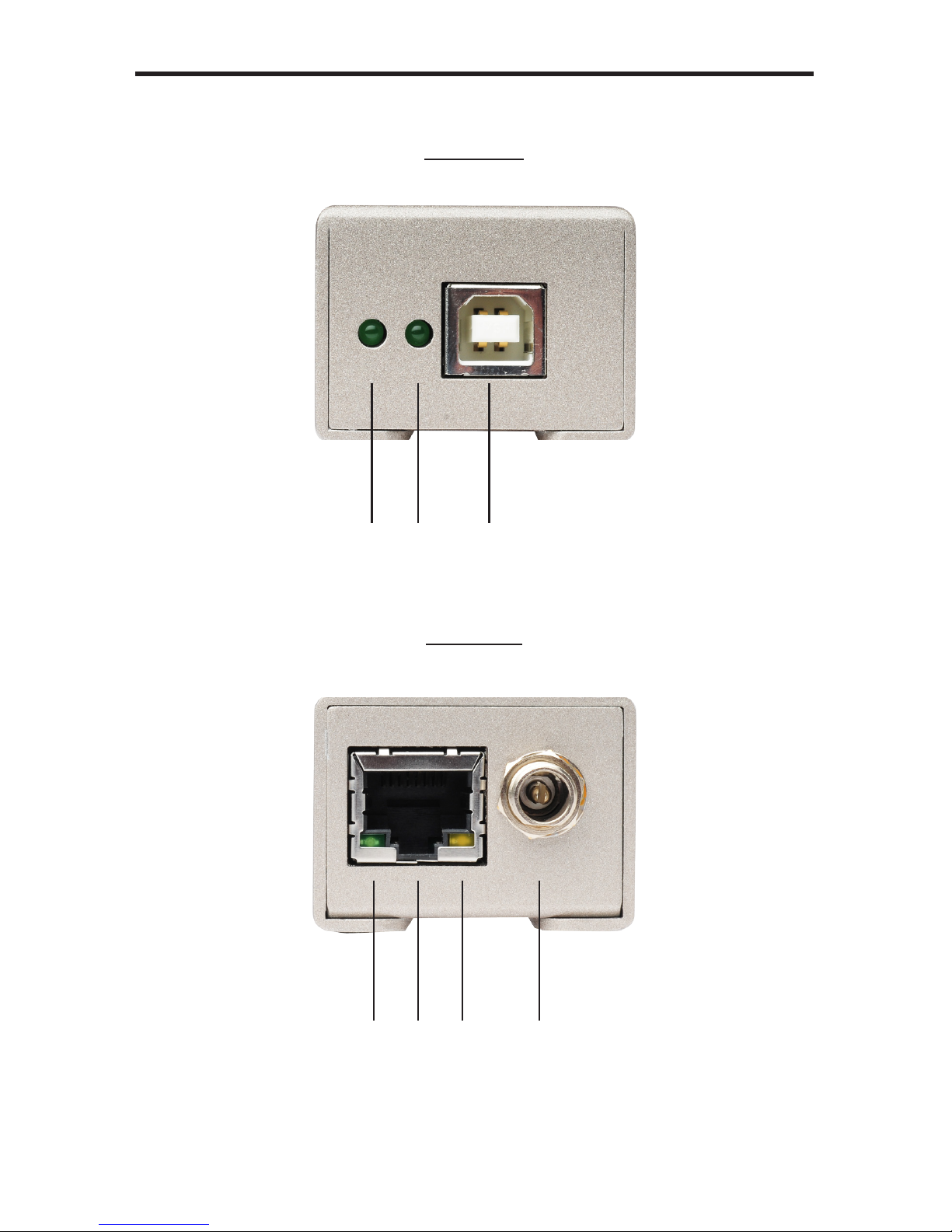
4
Front Panel
Back Panel
4 5 6 7
SENDER PANEL LAYOUT
1 2 3
Page 9

5
1 Power LED Indicator
This LED will become active once the host computer is connected to the sender
unit.
2 Host Connection LED Indicator
This LED will become active once a valid connection is made by the host source
and the USB 2.0 LR Extender.
3 USB “B” Input Connector
Connect the USB source to this input.
4 Link LED Indicator
This LED will become active once a valid connection is between the sender and
receiver units.
5 RJ-45 Connector Port
Connect a CAT-5, CAT-5e or CAT-6 cable between this port and the RJ45
connector port on the receiving unit.
6 Activity LED Indicator
This LED will be active when trafc is passing between the sending and
receiving units.
7 5V DC Locking Power Receptacle
Connect the included locking 5V DC power supply between this port and an
open wall power socket.
SENDER PANEL DESCRIPTIONS
Page 10

6
Front Panel
Back Panel
RECEIVER PANEL LAYOUT
1 2 3 4
5 6 7 8
Page 11

7
1 Power LED Indicator
This LED will become active once a valid connection is made between the
included 5V DC power supply and an open wall power socket.
2 Host Connection LED Indicator
This LED will become active once a valid connection is made by the host source
and the USB 2.0 LR Extender.
3 USB “A” Input Connector 1
Connect the USB device to this input.
4 USB “A” Input Connector 2
Connect the USB device to this input.
5 Link LED Indicator
This LED will become active once a valid connection is between the sender and
receiver units.
6 RJ-45 Connection Port
Connect a CAT-5, CAT-5e or CAT-6 cable between this port and the RJ45
connection port on the sending unit.
7 Activity LED Indicator
This LED will be active when trafc is passing between the sending and
receiving units.
8 5V DC Locking Power Receptacle
Connect the included locking 5V DC power supply between this port and an
open wall power socket.
RECEIVER PANEL DESCRIPTIONS
Page 12

8
How to Connect the USB 2.0 LR Extender
1. Connect the USB source to the USB 2.0 LR Extender sender unit using the
supplied USB A to B cable.
2. Connect up to two USB peripherals to the USB 2.0 LR Extender receiver
using user supplied USB cables.
NOTE: Powered USB hubs may be connected to these ports up to a maximum
connection of 14 USB peripherals (including hubs). Overall speed and power is
divided among the active devices.
3. Connect the USB 2.0 LR Extender sender and receiver units together with a
user supplied CAT-5, CAT-5e or CAT-6 cable.
NOTE: If eld terminating CAT-5 cables, please adhere to the TIA/EIA-568-B
specication. Please see the NETWORK CABLE WIRING DIAGRAM on page 10
for more details.
4. Connect the included 5V DC locking power supplies to both the Sender
and Receiver unit. Do not overtighten the screw assembly of the locking
connectors.
5. Connect each power supply to an available electrical outlet.
Checking the Installation
On the sending and receiving units, check that the Power, Host and Link LEDs
are on and that the Activity LED is blinking. If the Link LED and Activity LED are
permanently off then the cabling between the sending and receiving units are not
installed properly or is defective.
For Windows users (2000, XP, or Vista) open Device Manager to conrm that the
USB 2.0 LR Extender has installed correctly. Expand the entry for Universal Serial
Bus controllers by clicking the + sign. If the USB 2.0 LR Extender has been installed
correctly you should nd it listed as a Generic USB Hub.
For Mac OS X users open the System Proler to conrm that the USB 2.0 LR
Extender has installed correctly. In the left hand column under Hardware, select
“USB” and inspect the right hand panel. If the USB 2.0 LR Extender has been
installed correctly you should nd it listed as a Hub under the USB High-Speed Bus/
USB Bus.
CONNECTING AND OPERATING THE USB 2.0 LR EXTENDER
Page 13

9
TROUBLESHOOTING
Using the LED Indicators to Troubleshoot Issues
Power LED
The power LED indicators should be active once the included 5V DC power supply
has been properly connected between the receiving unit and an open wall power
socket. A non-active LED can indicate a power problem. Please check that the power
cable is properly connected and locked to the receiver unit. If the power LED on the
sender unit is unstable or not active, the host computer may not be supplying the
required 5V for operation. In that case, a separate 5V DC power adapter must be
purchased and connected the sender unit.
Host LED
The host LED indicators should be active once a valid USB source/output device
has been properly connected to the sending/receiving unit. On the sender, the LED
indicator will only be active once the source device is on. A non-active LED may
indicate that the source device is not on or properly connected. On the receiver, the
LED indicator will only be active when a USB devices is properly connected and is
recognized by the source. A non-active LED may indicate that a USB device is not
properly connected or recognized by the source. Please check all USB cables and
install the proper drivers for the connected USB device. Devices requiring more
power such as hard drives and cameras may require a powered USB hub.
Link LED
The link LED indicators should be active once a valid connection has been made
between the sending and receiving units. A non-active LED may indicate a problem
with the CAT-5 cabling. Please check terminations, patch panels, and cables. Use
other CAT-5 cables and test the units without using any patch panels.
Page 14
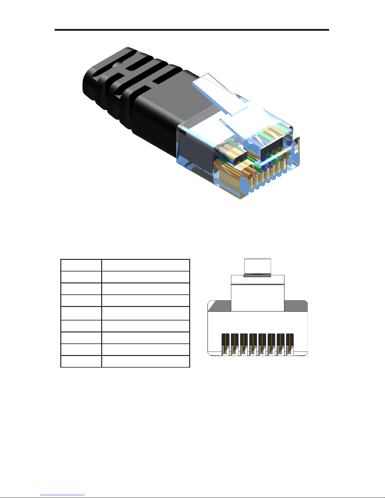
1 2 3 4 5 6 7 8
Gefen has specically engineered their products to work with the TIA/EIA-568-B
specication. Please adhere to the table below when eld terminating cable for
use with Gefen products. Failure to do so may produce unexpected results and
reduced performance.
Pin Color
1 Orange / White
2 Orange
3 Green / White
4 Blue
5 Blue / White
6 Green
7 Brown / White
8 Brown
10
CAT-5, CAT-5e, and CAT-6 cabling comes in stranded and solid core types.
Gefen recommends using solid core cabling. CAT-6 cable is also recommended
for best results.
Each cable run must be one continuous run from one end to the other. Splices or
punch-down blocks are not advised due to signal interruption.
NETWORK CABLE WIRING DIAGRAM
Page 15
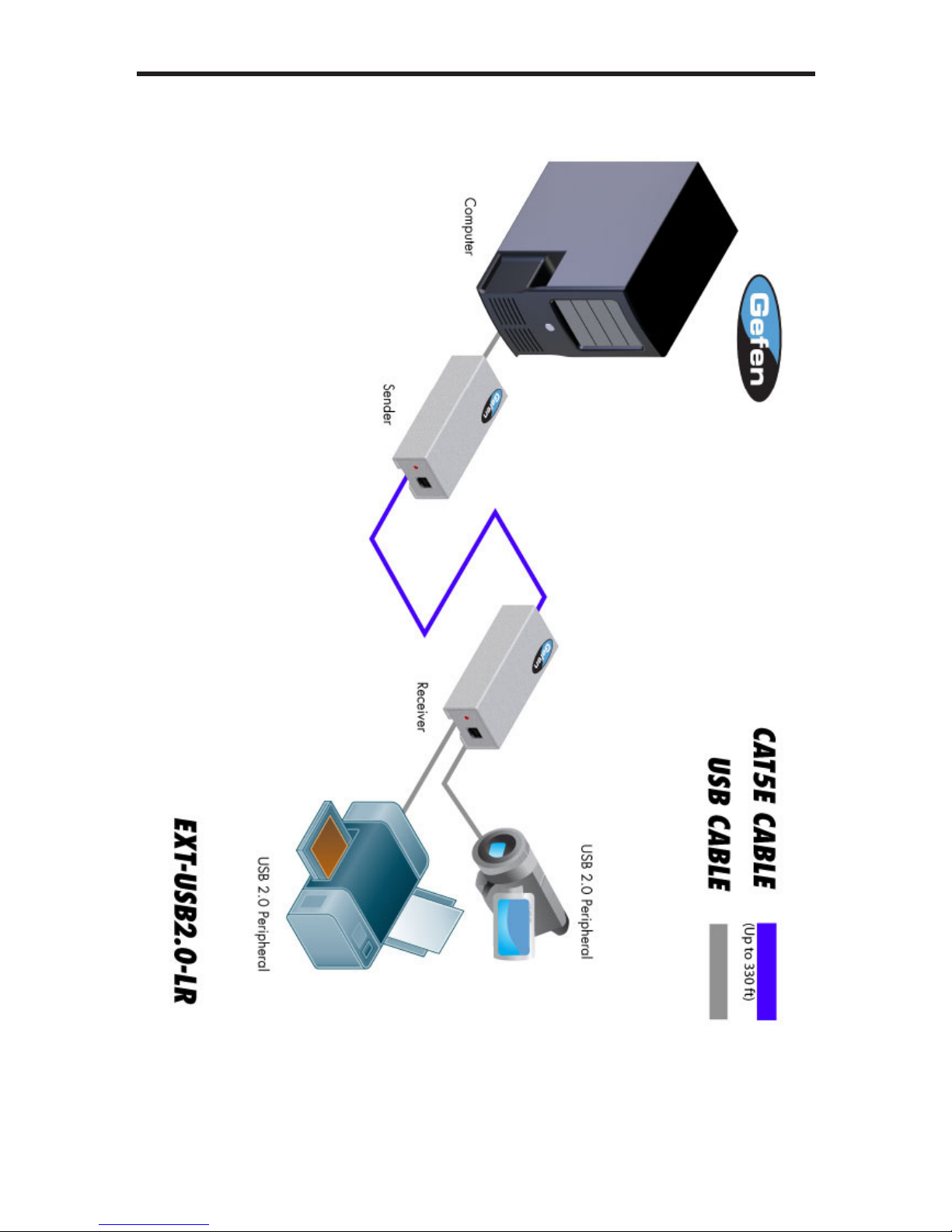
11
WIRING DIAGRAM
Page 16

12
USB 2.0 Speed........................................................................................ 480 Mbps
Link Connectors.............................................................................. RJ-45 Shielded
USB Connectors...........................................................Transmitter: (1) USB type B
USB Connectors.............................................................. Receiver: (2) USB type A
Power Supply (Sender / Receiver)................................................... 5V DC, locking
Power Consumption (max)...................................... 2.5W (Sender) 10W(Receiver)
Operating Temperature..............................................+41 to +113 °F (+5 to +45 °C)
Dimensions (W x H x D) (Sender / Receiver)............................... 3.7” x 1.4” x 1.8”
(94mm x 36mm x 46mm)
Unit Weight (Sender)..................................................................... 0.16 lb (0.07 kg)
Unit Weight (Receiver)...................................................................... 0.44 lb (0.2 kg)
Shipping Weight.................................................................................... 2 lbs (0.9 kg)
SPECIFICATIONS
Page 17

13
WARRANTY
Gefen warrants the equipment it manufactures to be free from defects in material
and workmanship.
If equipment fails because of such defects and Gefen is notied within two (2)
years from the date of shipment, Gefen will, at its option, repair or replace the
equipment, provided that the equipment has not been subjected to mechanical,
electrical, or other abuse or modications. Equipment that fails under conditions
other than those covered will be repaired at the current price of parts and labor in
effect at the time of repair. Such repairs are warranted for ninety (90) days from
the day of reshipment to the Buyer.
This warranty is in lieu of all other warranties expressed or implied, including
without limitation, any implied warranty or merchantability or tness for any
particular purpose, all of which are expressly disclaimed.
1. Proof of sale may be required in order to claim warranty.
2. Customers outside the US are responsible for shipping charges to and from Gefen.
3. Copper cables are limited to a 30 day warranty and cables must be in their original
condition.
The information in this manual has been carefully checked and is believed to
be accurate. However, Gefen assumes no responsibility for any inaccuracies
that may be contained in this manual. In no event will Gefen be liable for
direct, indirect, special, incidental, or consequential damages resulting from
any defect or omission in this manual, even if advised of the possibility of such
damages. The technical information contained herein regarding the features and
specications is subject to change without notice.
For the latest warranty coverage information, refer to the Warranty and Return
Policy under the Support section of the Gefen Web site at www.gefen.com.
PRODUCT REGISTRATION
Please register your product online by visiting the Register Product page under the
Support section of the Gefen Web site.
Page 18
This product uses UL listed power supplies.
Pb
Rev B2
 Loading...