

Page 1
D Patter
n
Signal Generato
r
TB-HD-SI
GGEN
r
Manual
Page 2

Page 3

echnical Suppor
t
Telephone (818) 772-910
0
(800) 545-690
0
Fax
(
818) 772-912
0
echnical Support Hours
:
:00 AM to 5:00 PM Monday through Friday, Pacifi c Tim
e
Write To
:
efen, LL
C
o Customer Servic
e
2
0600
Nordhoff St
hatsworth, CA 9131
1
www.gefentoolbox.com
upport@gefentoolbox.com
Notic
e
efen, LLC reserves the right to make changes in the hard ware, packaging and
any accompanying doc u men ta tion without prior written notice.
HDMI, the HDMI logo, and High-Defi nition Multimedia Interfac
e
are
trademarks or registered trademarks of HDMI Licensing in the United States and
ther
cou
ntries.
HD Pattern Signal Generator is a trademark o
f Gef
en, LL
C
Windows is a registered trademark o
f
icrosoft Corporation in the United States and other countries.
©
2012 Gefen, LLC. All rights reserved.
All trademarks are the property of their respective owners.
Rev A
6
ASKING FOR ASSISTANC
E
Page 4

CONTENT
S
1 Intr
oduction
2
O
peration Notes
Features
4 Top Panel Layou
t
Top Panel Descriptions
Back Panel Layou
t
7 Back Panel Descriptions
C
ontrol Panel Layou
t
C
ontrol Panel Descriptions
11 Connecting The GefenToolBox HD Pattern Signal Generator
11 Wiring Diagram
12 IR
emote Descriptio
n
14 HD Pattern Signal Generator Remote Installatio
n
15 Operating The GefenToolBox HD Pattern Signal Generator
15 Display Window
15 Timing Buttons
16 Pattern Buttons
16 Resetting the HD Pattern Signal Generator
17 Pattern Summar
y
17 Purit
y
18
C
olor Settings
20
C
olor Bars
20
Gray S
cal
e
21 Black White Lin
e
22 Plu
ge
23
Grid
23
G
radien
t
24
C
ircles
24 EDID
28 Audi
o
2 HDCP
4 Motio
n
34 Data Analysis
37
Sy
stem Setu
p
39 Timing Summar
y
41 HD Pattern Signal Generator Softwar
e
41 Installing the Softwar
e
44
C
onnecting the RS-232 cabl
e
45 Running the HD Pattern Signal Generator Softwar
e
47
S
electing the Timin
g
Page 5

CONTENT
S
48
S
electing the Patter
n
49 Unique Patterns
49
C
olor Setting Patter
n
1 Motion Patter
n
3 Favorite Timin
g
4 Favorite Patter
n
EDID Read / Writ
e
7 Translating EDID (Verbose Form
)
1
G
enerating the EDID Checksum
4
S
aving an EDID to a Fil
e
7
C
learing the EDID from Memor
y
8 Loading an EDID from a Fil
e
70
C
omparing EDID Data
72 Writing EDID to a Sin
k
73 Erasing the EDID of a Sin
k
74
O
pening Recent EDID Files
75 Autorun Confi guratio
n
76 Panel Control
77
G
etting the Hardware and Firmware Versio
n
78 RS-232 Control
79 RS-232 Commands
1 Notes
2 Wall Mounting Instructions
3 Specifi cations
4 Warrant
y
Page 6

Page 7

INTRODUCTIO
N
ongratulations on your purchase of the GefenToolBox HD Pattern Signal
enerator. Your complete satisfaction is very important to us.
About Gefen
efen delivers innovative, progressive computer and electronics add-on solutions
that harness integration, extension, distribution, and conversion technologies.
efen’s reliable, plug-and-play products supplement cross-platform computer
stems, professional audio/video environments, and HDTV systems of all sizes,
with hard-working solutions that are easy to implement and simple to operate.
efenToolBo
x
The GefenToolBox line offers portable and easy-to-install solutions for common
A/V system integration setups using HDMI connectivity. GefenToolBox products
are wall-mountable and small in size. GefenToolBox products are easily
transported in the fi eld and are ready for immediate and simple installations in
working environments.
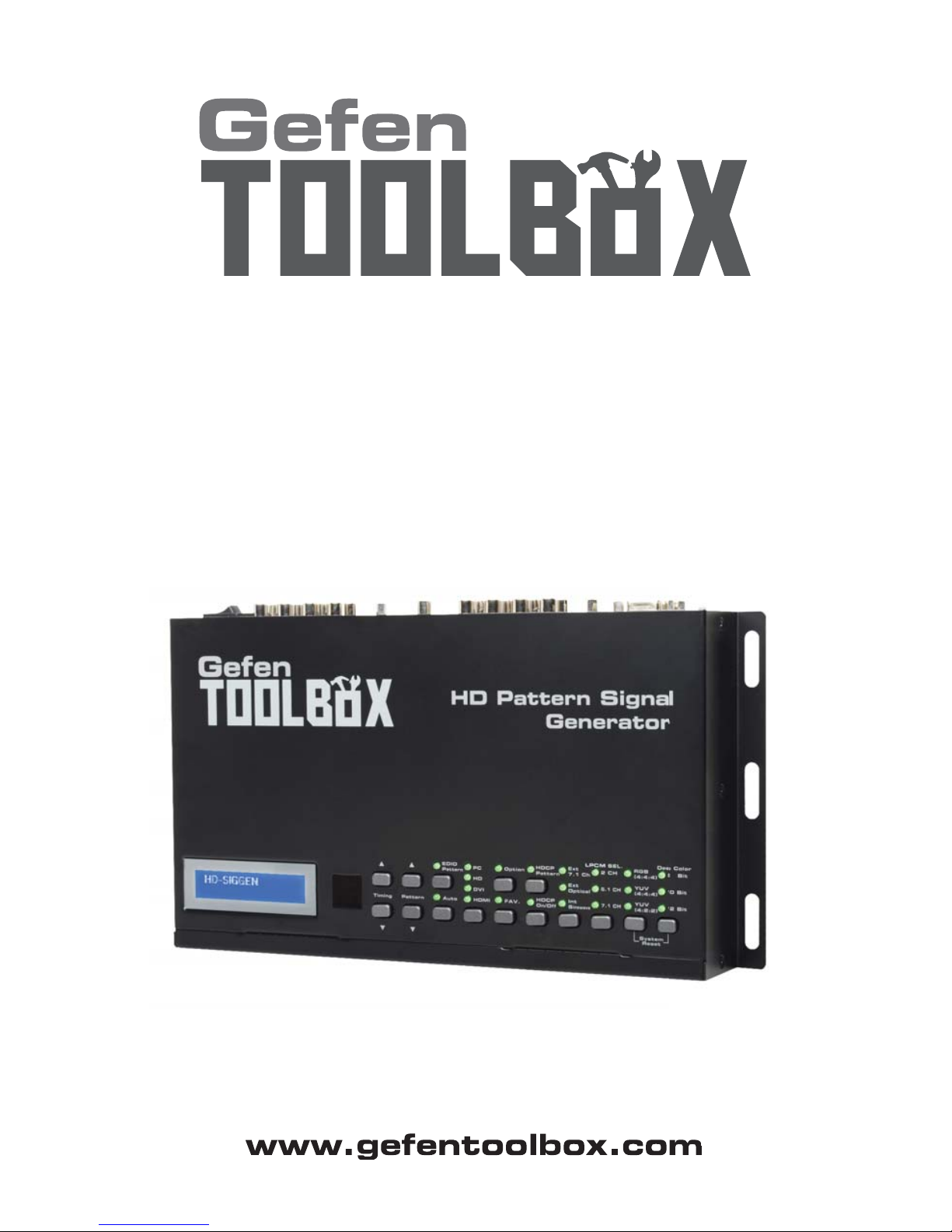
he GefenToolBox HD Pattern Signal Generator
The GefenToolbox HD Pattern Signal Generator is the most advanced testing device for your audio and video equipment. 39 built-in timings, 41 patterns, and four
4) data analysis patterns provide over a thousand testing combinations for both
analog and digital devices. The front panel LCD screen provides easy viewing of
unctions and features for each timing / pattern. This device can be convenientl
y
ontrolled via the front panel buttons, the IR remote or the downloadable software from the Gefen Web site. In addition to its portability, this signal generator
is wall-mountable and fi eld-upgradeable.
How It Works
onnect the HDMI output port of the GefenToolbox HD Pattern Signal Generator
to your HDTV display. Power-on all equipment. The front panel LCD will displa
y
all features and options of the active timing and pattern. You can feed digital or
analog audio into the generator’s rear panel and hear multi-channel digital audio
r
use
the built-in sine wave test tone.
Page 8

READ THESE NOTES BEFORE INSTALLING OR OPERATIN
G
HE GEFENTOOLBOX HD PATTERN SIGNAL GENERATOR
• The GefenToolBox HD Pattern Signal Generator can be controlled using a
oftware application and RS-232. Download this application from the Gefen
Web site at: http://www.gefen.com/kvm/support/download.js
p
OPERATION NOTE
S
Page 9

FEATURE
S
Features
•
ulti-format video output for SD and HD video up to 1080
p
•PC/HD resolutions up to UXGA / WUXGA (1920 x 1200
)
•
9 timings, 41 patterns, and 4 data analysis patterns
•
upports RGB 4:4:4, YCbCr 4:4:4, and YCbCr 4:4:2 color spaces
•
upports NTSC and PAL frame rates
• 2 CH, 5.1 CH, and 7.1 CH LPCM internal sine wave generator
•
-232 control via the downloadable software from the Gefen Web site.
•
mall form factor; easy to transpor
t
•
upports HD timings for VGA outpu
t
•
DCP Patter
n
•
upports reading and copying EDID functionality.
•
ser Friendly Interface - LCD Display, LED indicators and Software.
• Deep Color support up to 12-bi
t
•
DMI 1.3 and DVI 1.0 Complian
t
•
DCP Complian
t
Sample Applications
• Apparatus Testing and Troubleshootin
g
• Equipment Adjustmen
t
• EDID checkin
g
•
ource / Sink defi nitio
n
•
DCP Verifi catio
n
ackage Includes
•
1) GefenToolBox HD Pattern Signal Generator
•
1) 6ft. HDMI cable (M-M
)
•
1) IR Remot
e
•
1) 5 V DC Power Suppl
y
•
1) User Manual
Page 10

OP PANEL LAYOU
T
op Pane
l
Page 11

5
CD Displa
y
Displays pattern and timing information in addition to other functions used by the
ignal Generator.
R Windo
w
eceives signals from the IR Remote Control unit.
ontrol Panel
ee pages 8 - 10 for detailed information on the Control Panel.
OP PANEL DESCRIPTION
S
op Pane
l
Page 12
BACK PANEL LAYOU
T
Back Panel
5
7
10
1
1
12
Page 13

7
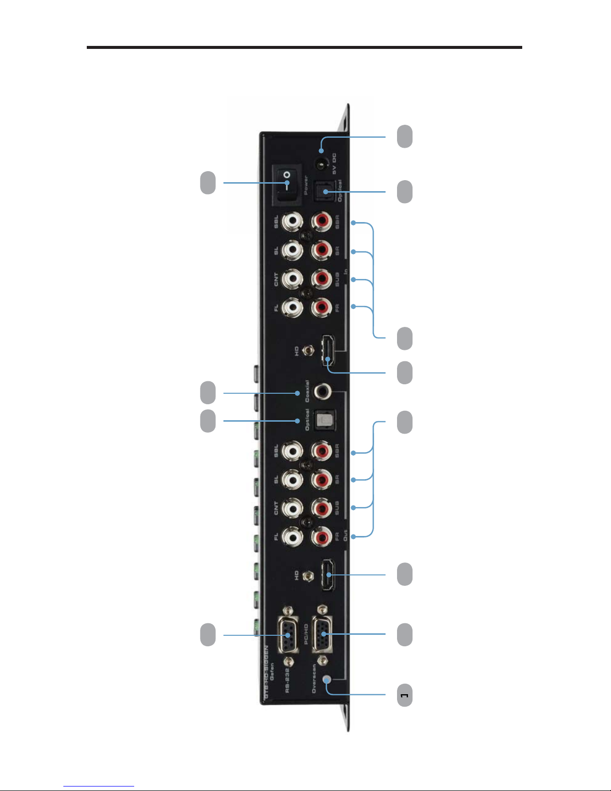
BACK PANEL DESCRIPTION
S
Overscan Button
By default, the GefenToolBox HD Pattern Signal Generator is set to
nderscan mode. If the video signal does not fi ll the entire display, press
this button once to switch to overscan mode. Press the
O
verscan button a
nd time to return to under
sca
n m
ode
.
VGA Outpu
t
onnect a VGA monitor to this port.
RS-232 Serial Por
t
onnect an RS-232 cable from this port to the computer running the HD Pattern
ignal Generator software.
4 HD Ou
t
onnect an HDTV display to this HDMI port. DVI displays can be connected
sing an HDMI to DVI cable or adapter.
5 Analog Audio Output
s
RCA type audio outputs (FL, FR, C, SUB, SL, SR, SSL, and SSR) are
available for connection to a separate amplifi er. Up to 6 discrete channels can
utilized.
6 TOSLink Output Connecto
r
onnect an optical cable from this output to an amplifi er or other audio output
vice.
7 S/PDIF Output Connecto
r
onnect a coax cable from this output to an amplifi er or other audio output
vice.
HD In
sed to connect a Hi-Def source to the Signal Generator using an HDMI cable.
DVI displays can be connected using an HDMI to DVI cable or adapter.
9 Analog Audio Input
s
RCA type audio outputs (FL, FR, C, SUB, SL, SR, SSL, and SSR) are
vailable for connection from a
source device
.
0 TOSLink Input Connecto
r
onnect an optical cable from the audio source device to this connector.
1 Power Switch
Turns the
Sig
nal Generator power ON or OFF.
2 5 V DC Power Connecto
r
onnect the included 5 V DC power supply to this connector.
Back Pane
l
Page 14
CONTROL PANEL LAYOU
T
Control Panel
7
10
1
3
1
4
17
1
8
0 22
2
6
5
12
15
1
6
19 2
1
2
3
25
1
1
Page 15

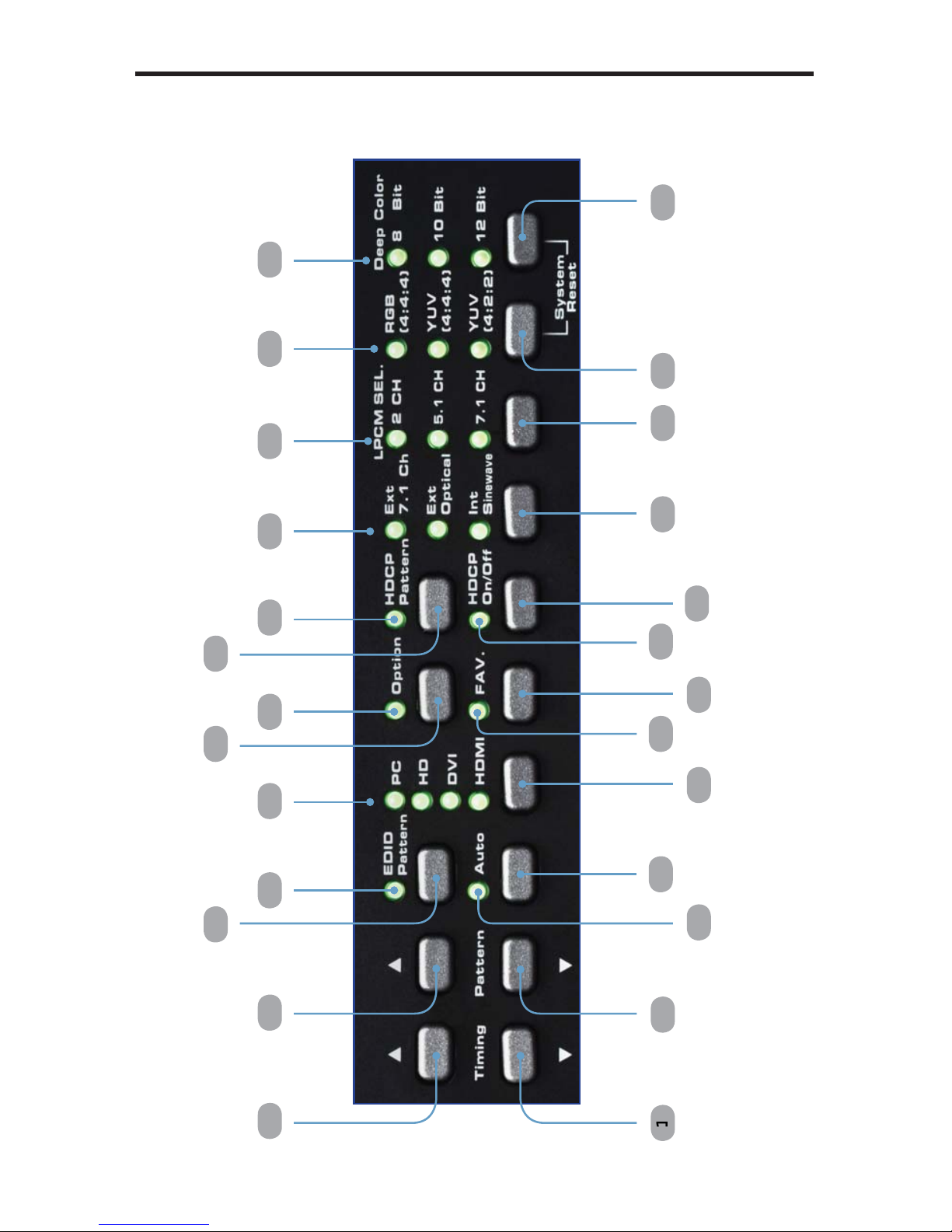
CONTROL PANEL DESCRIPTION
S
Control Panel
Timing (Down
)
cles backward through the list of timings
.
Timing (Up
)
cles forward through the list of timings.
Pattern (Down
)
cles backward through the list of patterns.
4 Pattern (Up
)
cles forward through the list of patterns.
5 Auto Indicato
r
This LED will glow bright green when the Signal Generator is placed in Auto
m
ode
.
6 Aut
o
Automatically cycles through a specifi ed list of timing / pattern sets. The Autorun
Demonstration mode is confi gured through the HD Pattern Signal Generator
oftware. See page 72 for details.
7 EDID Pattern
Press this button to jump directly to the EDID Pattern (P38). See page 21 for
more information on using the EDID Pattern.
EDID Pattern Indicato
r
This LED will glow bright green when the Signal Generator is placed in EDID
m
ode
.
9 Output Signal Button
elects between PC / HD (VGA), DVI, or HDMI signal types. Consecutively
ress this button to cycle through each of the signal types.
0 Output Signal Indicator
s
These LED indicators will glow bright green to indicate the current video output
mode (PC, HD, DVI, or HDMI
)
Fav. Button
onfi gures the generator to show only the patterns selected using the HD
Pattern Signal Generator software (see page 51 for details). This button is also
sed to change parameters when using certain patterns.
2 Fav. Indicato
r
This LED will glow bright green when the [Fav] button is pressed.
3 Option Button
The option button provides access to sub-functions within certain patterns.
Page 16

10
CONTROL PANEL DESCRIPTION
S
4 Option Indicato
r
This LED will glow bright green when the Signal Generator is in Option mode.
5 HDCP On / Off Indicato
r
This LED will glow bright green when HDCP content is being sent from the
ignal Generator.
6 HDCP Button
Enables / disables HDCP on the output. See page 29 for more information on
sing HDCP.
7 HDCP Pattern Button
Press this button to jump directly to the HDCP Pattern (P40).
8 HDCP Pattern Indicato
r
This LED will glow bright green when the HDCP Pattern (P40) is enabled.
9 Audio Selection Button
Pressing this button consecutively will cycle through the different audio output
options (see page 25 for details
)
0 Audio Selection Indicato
r
These LED indicators will glow bright green to indicate the current audio output
1 Audio Channel Button
Pressing this button consecutively will cycle through the different output audio
hannels (see page 25 for details
)
2 Audio Channel Indicato
r
These LED indicators will glow bright green to indicate the current audio channel
lection.
3 Color Space Selection Button
Pressing this button consecutively will cycle through the available output color
.
4 Color Space Selection Indicato
r
These LED indicators will glow bright green to indicate the current color space.
5 Bit Depth Selection Button
elects between 8-bit, 10-bit, or 12-bit color.
6 Bit Depth Indicato
r
These LED indicators will glow bright green to indicate the current color bit depth
election on the output.
Page 17
CONNECTING THE HD PATTERN SIGNAL GENERATOR
1
1
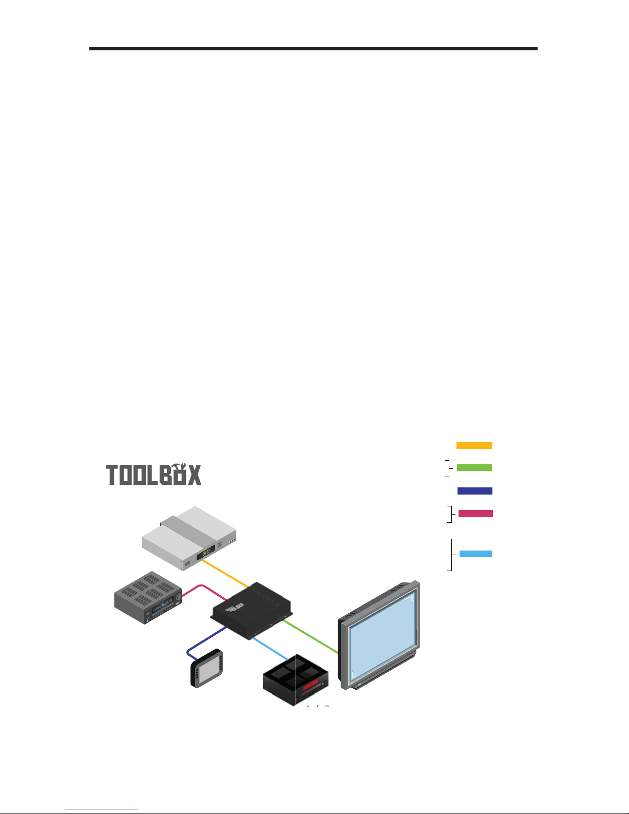
How to Connect the GefenToolBox HD Pattern Signal Generator
onnect an HDMI cable from the GefenToolBox HD Pattern Signal
enerator to the HDTV Display.
2.
onnect an optional external audio source to the HD Pattern Signal
enerator using an optical cable or RCA cables.
.
onnect the included 5V DC power supply to the power receptacle on the
D Pattern Signal Generator and connect the power cord to an available
lectrical outlet.
4. Turn on the HDTV display fi rst, then turn on the HD Pattern Signal
enerator.
Wiring Diagram for the GefenToolbox HD Pattern Signal Generator
GTB-HD-SIGGEN
Source Signal
Display
Audio Receiver
HDMI CABLE
Gefen
RS-232 CABLE
Audio Source
Signal Generator
RS-232 Controller
STEREO L /R AUDIO CABLE
DIGITAL AUDIO TOSLINK CABLE
HDMI CABLE
VGA CABLE
DIGITAL AUDIO S/PDIF CABLE
DIGITAL AUDIO TOSLINK CABLE
STEREO L /R AUDIO CABLE
i
Page 18
12
IR REMOTE CONTROL UNI
T
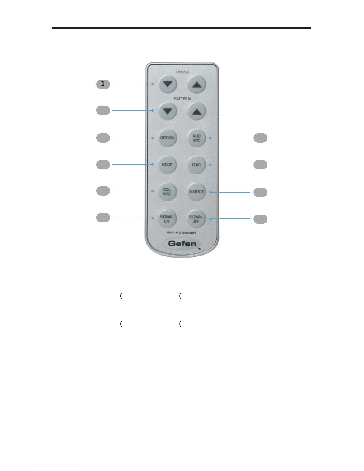
/ ▲ (Timing
)
cles forward
nd
backward
through the list of timings.
/ ▲ (Pattern
)
cles forward
nd
backward
through the list of patterns.
Option
The Option button provides access to sub-functions within certain patterns.
HDC
P
Enables / disables HDCP on the output. See page 29 for more information on
sing HDCP.
ol Sp
c
Pressing this button consecutively will cycle through the available output color
.
IR Remote La
y
out and Descriptions (RMT-HD-SIGGEN
)
10
7
5
Page 19

1
3
IR REMOTE CONTROL UNI
T
ignal On
Turns the signal ON after it has been turned off (A/V mute) using the Signal
Off
tton.
ignal Of
f
Turns the signal OFF (A/V mute).
Outpu
t
elects between PC / HD (VGA), DVI, or HDMI signal types. Consecutively
ress this button to cycle through each of the signal types.
EDID
Press this button to jump directly to the EDID Pattern (P38). See page 21 for
more information on using the EDID Pattern.
Aud Sr
c
Pressing this button consecutively will cycle through the different audio output
options (see page 25 for details).
Page 20
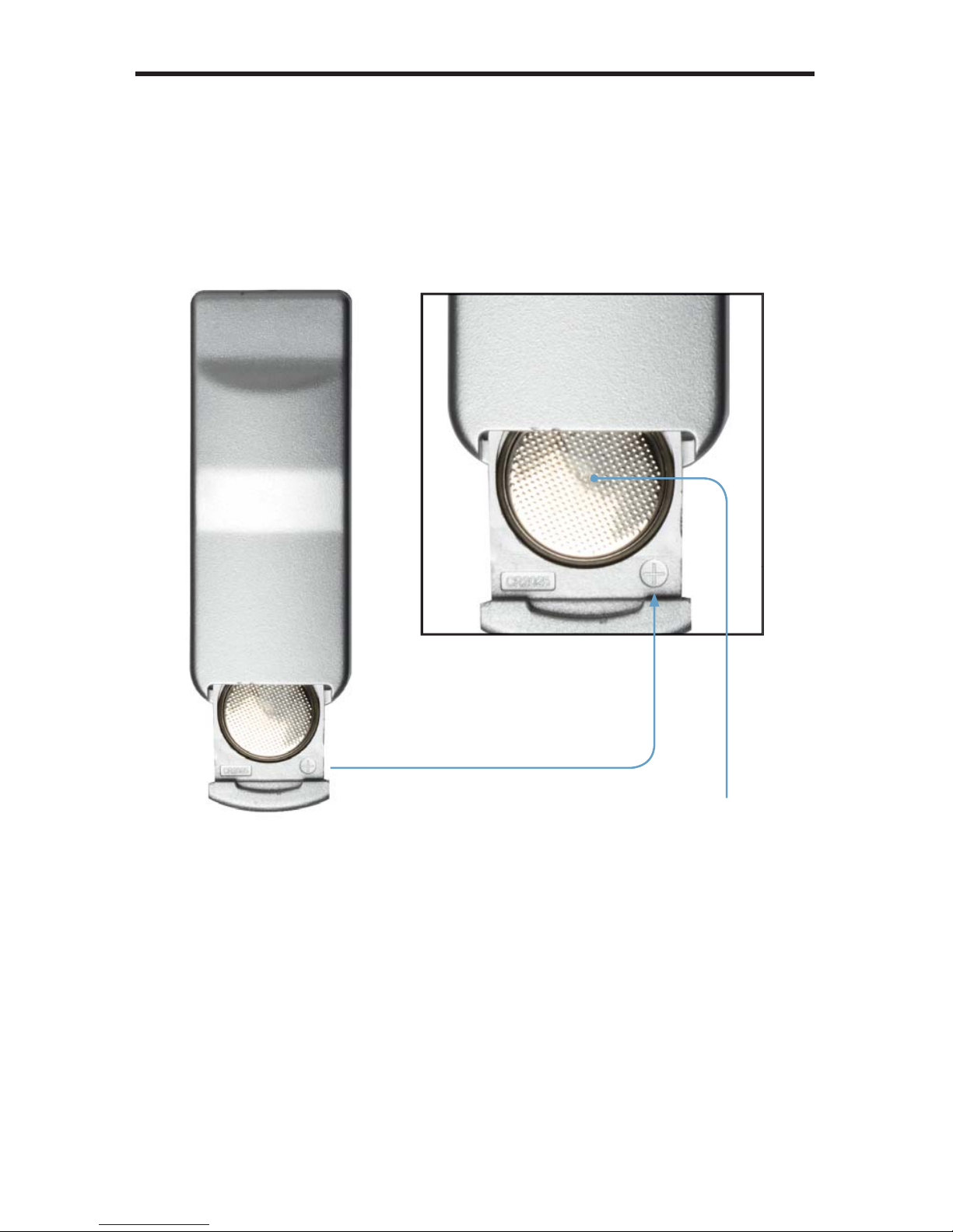
Installing the Batter
y
1.
old the IR remote control unit facing down and gently pull the battery tab
with
y
our thumb to reveal the battery slot.
2. Insert the included batter
y
into the battery slot. The battery slot indicates
that the positive (+) side of the battery must be facing up as shown below
:
.
lose the battery slot by sliding it closed.
1
4
IR REMOTE CONTROL UNI
T
Batter
y
Page 21
15
OPERATING THE HD PATTERN SIGNAL GENERATOR
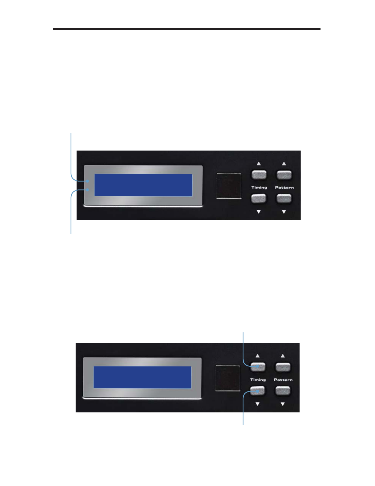
isplay Windo
w
Th
e
isplay Window o
f
the GefenToolBox HD Pattern Signal Generator is a
16-character, 2-line displa
y
. This display will show the currently selected timin
g
and pattern on the output. In addition, this display is also used for providin
g
information or messages about the connected devices. When the unit is
owered on, a screen similar to the following will be displayed
:
iming Buttons
To change the timing, use the ▲ and ▼ Timing buttons. The ▲ button will move
orward through the timings. Use the ▼ button will move backward through the
timings. See pages 36 - 37 for a list of supported timings.
urrently selected timin
g
urrently selected patter
n
cles forward
through the timings
cles backward
through the timings
Page 22
1
6
OPERATING THE HD PATTERN SIGNAL GENERATOR
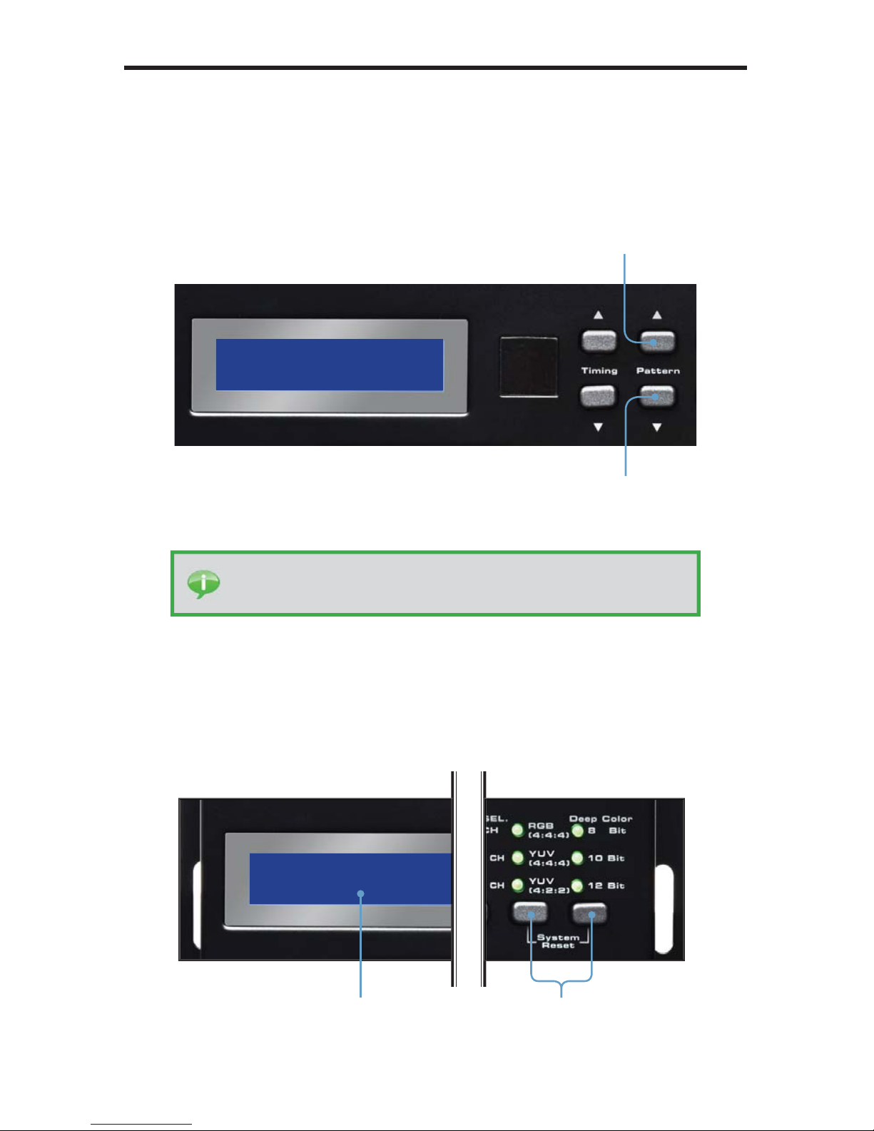
attern Buttons
To change the pattern, use the ▲ and ▼ Pattern buttons. The ▲ button will
ove forward through the patterns (see the pages 14 - 35 for a list of available
atterns). Use the ▼ button to move backward through the patterns.
Resetting the HD Pattern Signal Generator
To reset the HD Pattern Signal Generator to factory default settings,
imultaneously hold down the
olor Space Selection button and the Bit Depth
election button. During the reset sequence, the LCD display will show the
:
stem Rese
t
cles forward
through the timings
cles backward
through the timings
Pr
ess to rese
t
the Generator
stem Rese
t
IP
:
Pr
ess and hold
the ▲ or ▼ buttons to rapidly cycle through
ither the timings or patterns.
Page 23

ATTERN SUMMARY
17
urit
y
attern 01 - Pattern 08 (P01 - P08
)
Press the [OPTION] button to switch between Full Screen and Windowed format.
P01 Whit
e
P02 Blu
e
P03 Re
d
P04 Magenta
P05
G
ree
n
P06
Cyan
P07 Yellow
P08 Blac
k
ed (P03) and Green (P05) are often used to check color purity. When using the
ed pattern, no other color should be present on the screen. If the Red pattern
appears tinted, then this is an indication that the color purity should be adjusted. The
ed pattern can also be used to ensure that there is no interference between the
ound and the chroma carrier, in addition to adjusting the long play delay level to
inimum fl icker.
Page 24
1
8
ATTERN SUMMARY
reen (P05) provides a color purity check for display devices that use three in-line
uns. The in-line confi guration defi nes guns which are positioned horizontally with
the green gun located in the center (R-G-B).
Blue
(
P02) is a complementary color. This pattern is frequently used to test color
erformance.
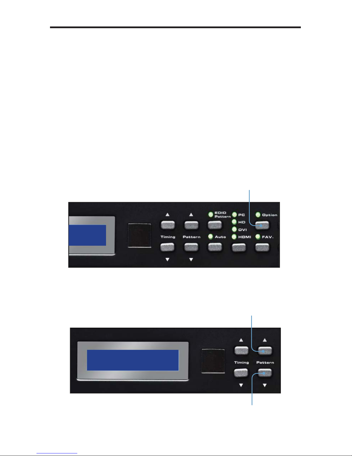
Color Settings
attern 09 - Pattern 13 (P09 - P13
)
Press the [OPTION] button to enter the pattern options. Use the Pattern [UP] and
DOWN] buttons to adjust the color level. Press the [FAV] button to switch between
ull and limited color range.
Enter pattern options
Adjusts color level
Ad
j
usts color level
Page 25
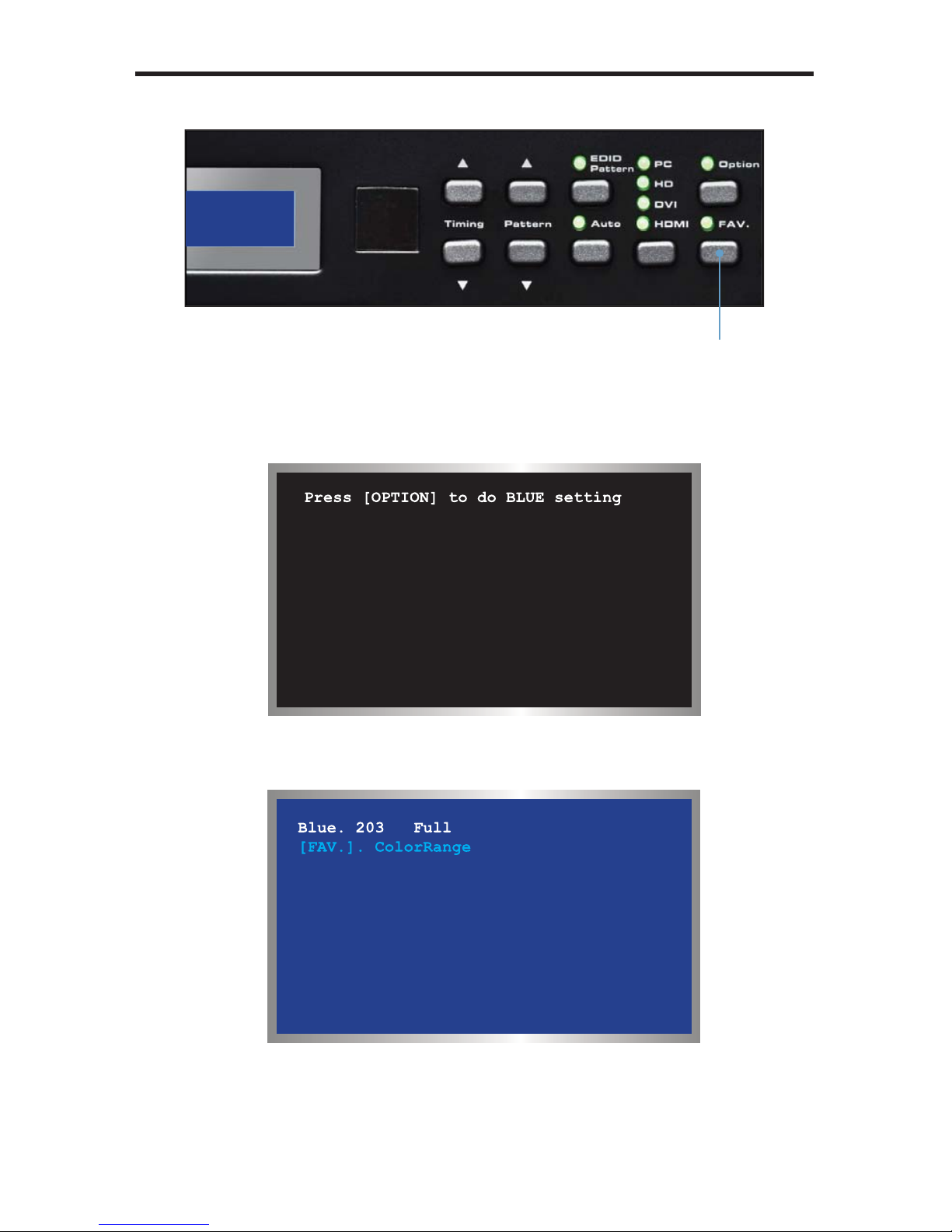
19
ATTERN SUMMARY
When using Pattern 09 - Pattern 12, a black screen will be displayed, fi rst. Use the
PTION] to enable to the pattern. The Blue Pattern (P11) is illustrated below
:
The BLUE Setting pattern (P11) with blue level at 203 and set to the Full color
ange setting using the [FAV] button
:
Pattern 13 (P13) will appear as a white screen and can only be controlled usin
g
-232. See page 46 for more information.
witch between full
and limited color ran
ge
Page 26

0
ATTERN SUMMARY
Color Bars
attern 14 - Pattern 17 (P14 - P17
)
There are four different color bar patterns. Use the [OPTION] button on Pattern 14
P14) and Pattern 16 (P16) to switch between 75 IRE (Option LED indicator OFF
)
and 100 IRE (Option LED indicator ON).
P14
C
olor Bar
P15
S
MPTE Color Bar
P16
S
plit Bar
P17 RGB Dela
y
ray Scal
e
attern 18 - Pattern 22 (P18 - P22
)
ray scale patterns can be used to locate faulty linearity of the video amplifi er or gra
y
cale settings. Use the [OPTION] button on Gray-11 (P19) to alternate between the
two patterns. Option LED indicator OFF = Vertical Pattern, ON = Cross Pattern.
P18
Gray-8
P19
Gray-11
P20
Gray-32
P21
Gray
-256
P22 H.Gray-1
1
Page 27

ATTERN SUMMARY
Black White Lin
e
attern 23 -Pattern 26 (P23 - P26
)
The vertical pattern serves as a test for the horizontal bandwidth and phase behavior
o
f
a color monitor. This pattern can also be used to verify the video amplifi er and
olor temperature.
The horizontal pattern can check the vertical bandwidth and phase behavior, in
addition to verifying the video amplifi er integrity and color temperature.
P23 V Line ONOF
F
P24 H Line ONOFF
P25 MULTI-BUR
ST
P26 Dual Needl
e
Page 28
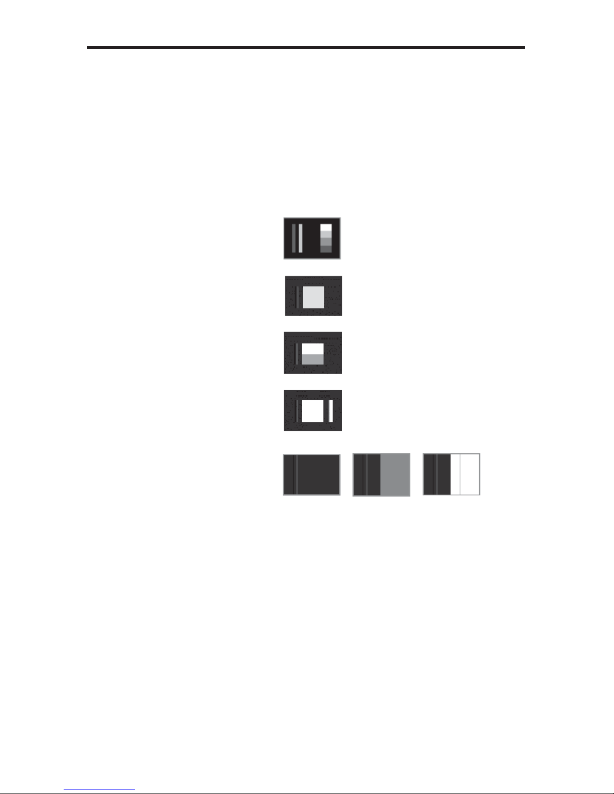
2
ATTERN SUMMARY
lu
ge
attern 27 - Pattern 31 (P27 - P31
)
Pluge (Picture line up) patterns are used to perform accurate and consistent line-up
o
f
the output signal (video). The concept behind Pluge patterns is to adjust the
brightness control so that the fi rst bar is invisible, while the second bar remains
visible.
se the [OPTION] button on PLUGE-5 (P31) to cycle through each of the Pluge
variations.
P27 PLUGE-
1
P28 PLUGE-
2
P29 PLUGE-
3
P30 PLUGE-4
P31 PLUGE-
5
By default, Pattern 31 (P31) is set to the fi rst pluge pattern. During this state, the
ption LED indicator will be OFF.
Press the [OPTION] button to display the second Pluge-5 variation pattern. The
ption LED indicator will glow bright green.
Press the [OPTION] button a third time to display the third Pluge-5 variation pattern.
The Option LED indicator will glow bright green.
Pressing the [OPTION] button a fourth time will display the original Pluge-5 pattern.
The Option LED indicator will turn OFF.
Page 29
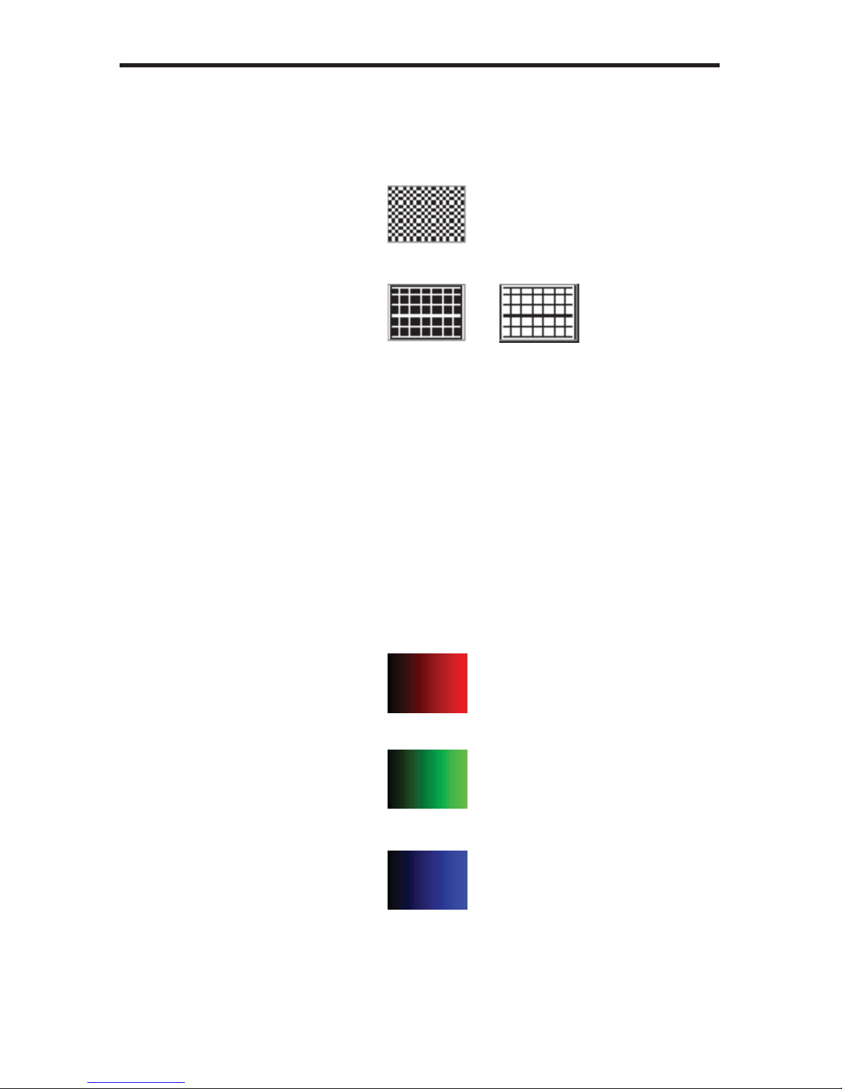
ATTERN SUMMARY
rid
attern 32 - Pattern 33 (P32 - P33
)
rid and cross patch patterns are mainly used for detecting corner convergence (“pin
ushions”).
P32
G
RID
P33
C
ross Hatc
h
Press the [OPTION] button on Pattern 33 (P33) to toggle between the black/white
ption LED indicator is OFF) and white/black (Option LED indicator is ON) cross
atch patterns.
radien
t
attern 34 - Pattern 36 (P34 - P36
)
radient patterns are used to detect linearity faults in the video amplifi er. Non-
inearities will usually result in color level compression.
P34
G
RAY-256-
R
P35
G
RAY-256-
G
P36
G
RAY-256-B
Page 30
ATTERN SUMMARY
Circles
attern 37 (P37
)
Produces a pattern with large circles on the screen. This pattern is primarily used for
hecking the overall geometry and linearity of the display.
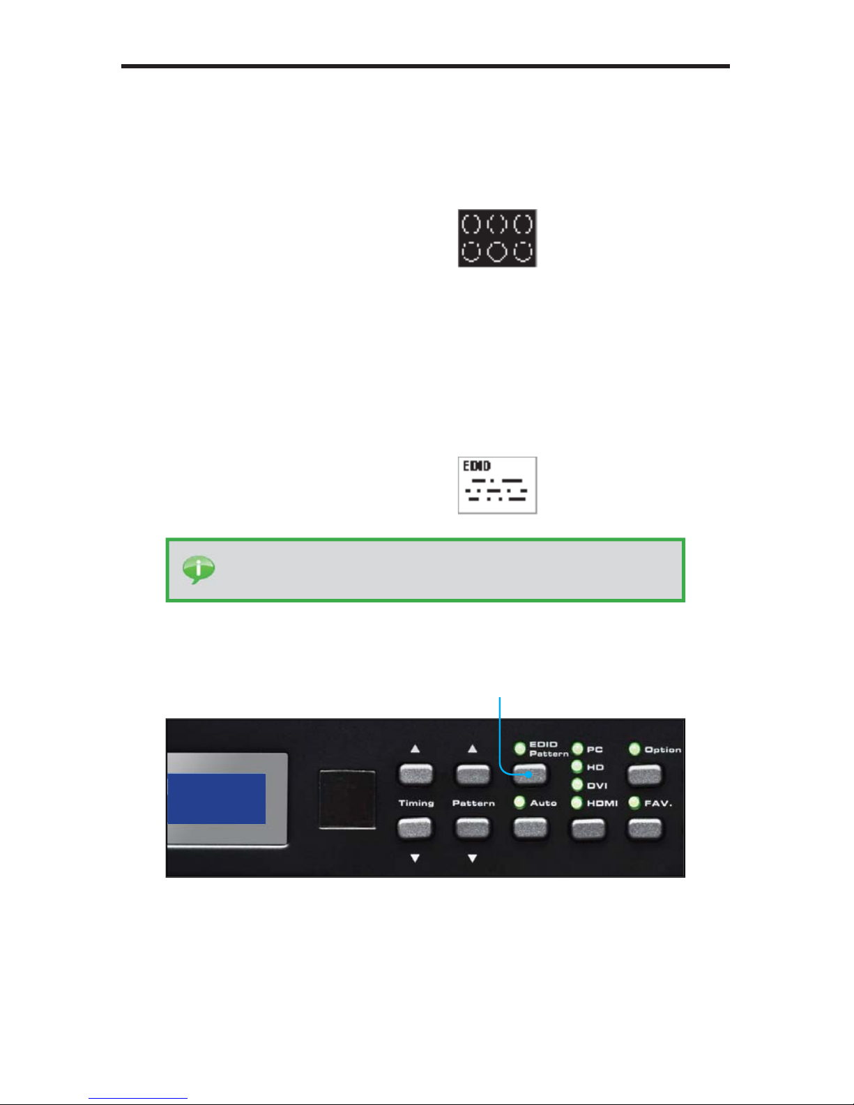
P37
CIRCLES
DI
D
attern 38 (P38
)
Displays the EDID pattern screen. This pattern is used to analyze the EDID data of
the connected sink (display, A/V receiver, etc).
P38 EDID Analysis
The EDID pattern supports up to two
(2)
blocks (Block0 and Block1).
ump directly to th
e
EDID pattern (P38
)
f
rom any patter
n
IP
:
The EDID pattern (P38) can also be directly accessed by pressin
g
the [EDID] button on the top panel.
Page 31
5
ATTERN SUMMARY
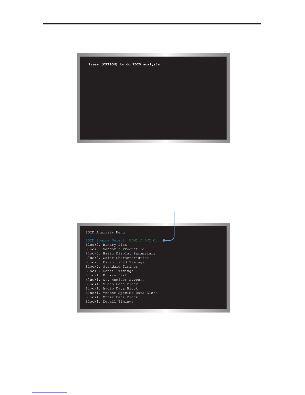
When the EDID pattern is selected, the display will appear as follows
:
To use the EDID pattern, follow the instructions below
:
1 Press the [OPTION] button.
2 The EDID Analysis Menu will be displayed. The fi rst line of the menu will be
ighlighted in blue.
Press the [OPTION] button to select between HDMI / DVI Out, HDMI / DVI In, or
V
G
A PC / HD Out.
EDID Source Selec
t
is highlighted in blue.
Page 32
ATTERN SUMMARY
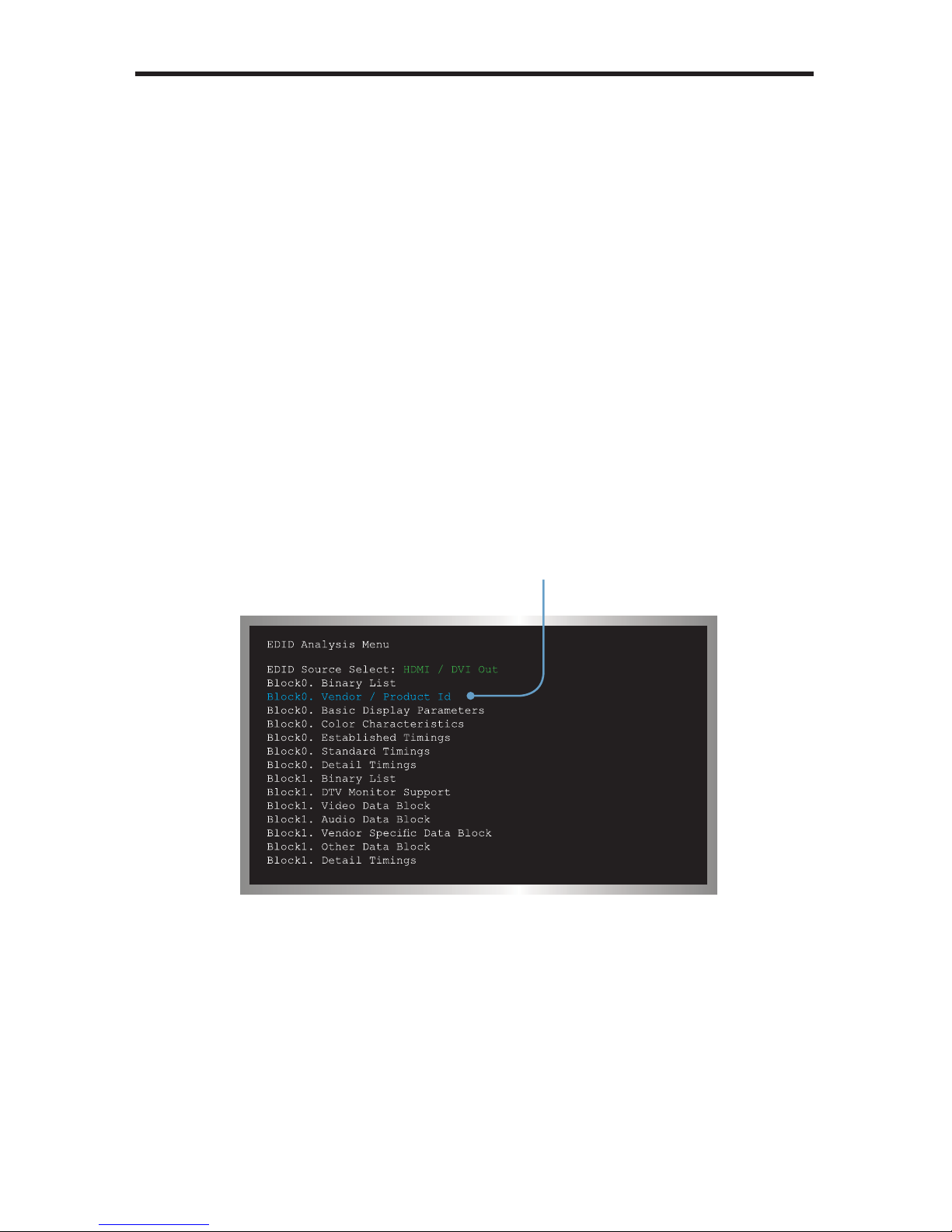
• HDMI / DVI Ou
t
eads the EDID of the sink (display, A/V receiver, etc) connected to the HD
Pattern Signal Generator.
• HDMI
/
DVI In
eads the built-in EDID of the HD Pattern Signal Generator.
•
V
GA PC / HD Ou
t
eads the EDID of the display connected to the VGA port of the HD Pattern
ignal Generator.
4 In this example, the HDMI / DVI Out option will be used. An HDMI cable is
onnected between the sink and the HD Out port of the HD Pattern Signal
enerator. Any of the three options (mentioned above) could be used,
depending upon the application.
Pr
ess
the
Pattern button twice to scroll down to the Block0. Vendor /
Product Id option.
Press the [OPTION] button on the top panel to display this section of the EDID
ta structure.
Block0. Vendor / Product
Id is highlighted in blue.
Page 33

7
ATTERN SUMMARY
The HD Pattern Signal Generator will display the Vendor / Product Id EDID
information on the screen.
Your Vendor
/
Product Id EDID information will most likely differ from the example
low
:
In this example, the HD Pattern Signal Generator reported the following EDID
information for the Vendor / Product Id in Block
0:
DID OUT Analysis Block0 Page
2
nuf
acture
r Name. GE
F
r
oduct Code
. 1
01
N.
0k o
f Manuf
acture
. 5
0
r of Manuf
acture. 2009
DID Ver
sio
n. 1.
3
nal Type. D
igital
FP 1.x. Not Compatibl
e
7 Press the [OPTION] button to return to the EDID Analysis Menu or press the
▲ or ▼ Pattern buttons to display each section of the EDID data structure,
without having to return to the EDID Analysis Menu.
To exit the EDID pattern, return to the EDID Analysis Menu (press the
PTION] button if required) to return to the EDID Analysis Menu, then press
the [EDID] button on the top panel. Press the ▲ or ▼ Pattern buttons to
elect another pattern.
Page 34

ATTERN SUMMARY
Audi
o
attern 39 (P39
)
This pattern displays the audio information of the connected source device, such as
the number o
f
audio channels, sampling rate, and I
(Intergrated Interchip Sound
)
data.
P39 AUDI
O
The table below provides a listing of the audio input and audio output combinations
when using the Audio Pattern (P39).
Analog 7.1
Ch
ptical / Coa
x
DMI
Ext. 7.1
Ch
Bypass LPCM 2CH @ 48 kHz Ext. 7.1
Ch
Ext. Optical 2
CH
Bypass Bypass
Int. Sinewav
e
2CH, 6CH, 8CHLPCM 2 CH @ 48 kHz Ext. Optical
xternal 7.1 Channel Audio Inpu
t
In the example below, the Audio Pattern is shown using the external 7.1 channel
audio input.
urrent Audio input
lection.
In
p
u
t
Outpu
t
Page 35

9
ATTERN SUMMARY
In the example above, the Audio Pattern is shown using the external 7.1 channel
audio input. The Audio Input Selection button is used to change the audio input type.
Text that is hi
g
hlighted in yellow indicates that the value may be changed. In the
illustration above, the HDMI output can be toggled between 2 channel LPCM and 6
hannel (5.1) channel LPCM audio using the Audio Channel selection button.
Note that HDMI does not support 8 channels (7.1) of audio. Therefore, the 7.1 CH
option cannot be selected.
Audio channel
lection butt
on
Audio Input
election butto
n
Page 36

0
ATTERN SUMMARY
xternal Optical Audio Inpu
t
hanging the audio input to EXT OPTICAL, using the Audio Input Selection button
will produce the following screen
:
In the example above, since no optical input was used, the Source Format Detection
displays
n
e
Internal Sinewave Generator
The third option (INT SINEWAVE) uses the internal sine wave generator
:
NOTE
:
The External
O
ptical Audio Input does n
ot
support bitstream
decoding.
Page 37

ATTERN SUMMARY
The I
data line option is only present when the HD Pattern Signal Generator is
et to 5.1 CH or 7.1 CH audio. In 2 CH mode, the I bus can only be enabled or
disabled (muted). Use the [FAV] button to change the I bus options.
When the output is set to 5.1 (6 channel) audio, the I
options are
:
S Bus: On, Mute, SD0, SD1, and SD
2
When the output is set to 7.1 (8 channel) audio, the I
options are
:
S Bus: On, Mute, SD0, SD1, SD2, and SD
3
elects the serial
ta lin
e
hanges the
ampling Rat
e
Audio channel
lection butt
on
Page 38

2
ATTERN SUMMARY
HD
CP
attern 40 (P40
)
This pattern displays HDCP information such as handshaking and link integrity test.
I
f
the sink (output device) is a repeater, both the B
and B
KSv’
are displayed.
P40 HDCP
When the HDCP pattern is selected, the display will appear as follows
:
By default, HDCP is disabled. Press the [HDCP] button on the front panel to enable
DCP. HDCP can be enabled or disabled for any pattern, except for the EDID
attern (P38).
Enables or di
sables
DCP
The HDCP pattern (P40) can also be directly accessed by press-
ing the [HDCP] button on the top panel.
Page 39
ATTERN SUMMARY
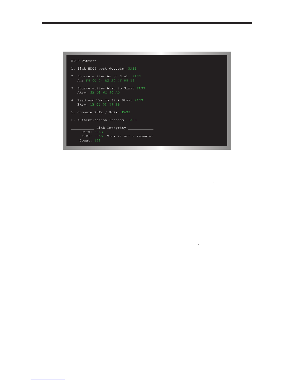
nce HDCP has been enabled, the screen will appear similar to the followin
g:
The HDCP pattern provides a full three phase authentication
:
hase 1
:
A
to the sink
/
receiver (Rx).
The receiver responds by sending its own KSV
(
B
The Receiver also sends the repeater bit, used to determine if the sink / receiver
acts as a repeater. During this step, the transmitter also verifi es tha
t
B
has
ot been revoked and has the proper forma
t
If
A
and
B
are deemed to be valid, then the receiver (sink) and transmitter
source) each generate R0 (the receiver generates
is read by the
transmitter and compared with R If
= R
then the authentication phase is
uccessful. If they are not equal, HDCP authentication will fail.
hase 2
:
As long as R0 = R0’, the transmitter will begin sending encrypted video.
hase 3
:
Every 128 frames (2 sec), the Tx and Rx generate a value
which is similar to
the
values. Comparing these values between the Tx and Rx verifi es that the
ink is synchronized.
Page 40

ATTERN SUMMARY
In the example above, the HDCP authentication process is successful. Note that the
ink (Rx) was not identifi ed as a
epeate
r
otion
attern 41 (P41
)
This pattern produces a 10x10 pixel block that moves horizontally across the screen,
rom right to left. See page 48 for details on modifying this pattern.
P41 Moti
on
ata Analysis
attern 42 - Pattern 44 (P42 - P44
)
These patterns are used to detect HDMI / DVI timings, input video packets, and
infoframe analysis.
P42 In Timin
g
The In Timing pattern will display timing information about an incoming video signal.
onnect the source signal to the HDMI or VGA input connector.
If no input signal is detected (or is not connected), the top line will display No Signal.
No input signal
tect
ed
NOTE
:
A repeater is defi ned as an active device which has one or
ore HDMI inputs and one or more HDMI outputs that work with HDCP.
A repeater is an active device because it decrypts HDCP content on the
input (Rx) and re-encrypts on the output (Tx
).
Page 41

5
ATTERN SUMMARY
When a valid video input signal is detected, the In Timing pattern will displa
y
information similar to the followin
g:
Press the [OPTION] button to perform a hot-plug (HPD) event. Triggering an HPD
vent is the similar to disconnecting and reconnecting the input source.
P43 In Vide
o
The In Video pattern provides information about color space, color depth, extended
olorimetry (if applicable), HDCP, and AVI infoframe information.
Page 42

As with the In Timing pattern (P42), if a valid signal is not detected on the input, the
top line will display No Signal.
Press the [
O
PTION] button to trigger an HPD event.
P44 In Audi
o
The In Audio pattern provides audio information, including sampling rate, bit depth,
audio encoding, and the number of audio channels.
If an audio signal is not detected on the input, the In Audio Detection will indicate No
ignal.
se the [OPTION] button to trigger an HPD event.
ATTERN SUMMARY
No input signal
tect
ed
Page 43

7
ATTERN SUMMARY
System Setup
attern 45 (P45
)
Built-in Rx EDID setup, IR remote address setup.
P45
Sy
stem Setu
p
When the System Setup pattern is selected, the display will appear as follows
:
Press the [OPTION] button to bring up the following screen
:
Press [OPTION] to do system setup
System Setup
►Copy OUT EDID to IN EDID...
Copy IN EDID to OUT EDID...
IR Remote Address:0
Exit
[PATTERN+/-].Select [OPTION].Enter
Page 44

ATTERN SUMMARY
There are four options under the System Setup pattern. Use the ▲ or ▼ buttons to
elect the desired option. Press the [OPTION] button to accept the selection.
1 Cop
y
OUT EDID to IN EDI
D
opies the EDID from the device/display connected to the HD Pattern Signal
enerator and stores it in a local buffer on the unit. The EDID can be uploaded
to another output device.
Copy IN EDID to OUT EDI
D
opies the EDID data stored in the local buffer (using the Copy OUT EDID to
IN EDID option), to the device connected to the output of the HD Pattern Signal
enerator.
IR Remote Address
hanges the IR channel of the HD Pattern Signal Generator, when used with
the IR Remote Control Unit. An IR Remote Control Unit is not included with this
roduct at this time.
xi
t
eturns to the fi rst screen of the System Setup pattern.
WARNING: The EDID data is stored in volatile memor
y
. Any power
disruption will erase the contents of the buffer.
Page 45

9
IMING SUMMARY
The following table lists the available graphic and video timings used by the HD
Pattern Signal Generator
.
iming Number
imin
g
T
01
40 x 480 @ 60 Hz
T
02
40 x 480 @ 72 Hz
T
03
40 x 480 @ 75 Hz
T
0
4
40 x 480 @ 85 Hz
T
05
00 x 600 @ 56 Hz
T
06
00 x 600 @ 60 Hz
T
07
00 x 600 @ 72 Hz
T
08
00 x 600 @ 75 Hz
T
09
00 x 600 @ 85 Hz
T1
0
1024 x 768 @ 60 H
z
T1
1
1024 x 768 @ 70 H
z
T1
2
1024 x 768 @ 75 H
z
T1
3
1024 x 768 @ 85 H
z
T14 1280 x 960 @ 60 H
z
T1
5
1280 x 960 @ 85 H
z
T1
6
1280 x 1024 @ 60 Hz
T1
7
1280 x 1024 @ 75 Hz
T1
8
1280 x 1024 @ 85 Hz
T1
9
1600 x 1200 @ 60 Hz
T2
0
1920 x 1200 @ 60 Hz
T2
1
720 x 480i @ 59 H
z
T2
2
720 x 480i @ 60 H
z
T2
3
720 x 480p @ 59 H
z
T24 720 x 480p @ 60 H
z
T2
5
1280 x 720p @ 59 Hz
T2
6
1280 x 720p @ 60 Hz
T2
7
1920 x 1080i @ 59 H
z
T2
8
1920 x 1080i @ 60 H
z
T2
9
1920 x 1080p @ 59 Hz
T
30
1920 x 1080p @ 60 Hz
Page 46

0
IMING SUMMARY
iming Number
imin
g
T
31
720 x 576i @ 50 H
z
T
32
720 x 576p @ 50 H
z
T
33
1280 x 720p @ 50 Hz
T34 1920 x 1080i @ 50 Hz
T
35
1920 x 1080p @ 50 Hz
T
36
1920 x 1080p @ 23 Hz
T
37
1920 x 1080p @ 24 Hz
T
38
1366 x 768 @ 60 H
z
T
39
1366 x 768 @ 50 H
z
NOTE
:
Analog PC output (VGA) only supports VESA (VGA through
WUXGA) timings. Analog HD output only supports SD / HD (480i,
480p, 576i, and 576p) timings. HDMI / DVI output supports all
timings. Timings cannot be edited.
Page 47

HD-SIGGEN Softwar
e
The HD Pattern Signal Generator can be controlled via RS-232 on a PC runnin
g
Windows®, using the HD-SIGGEN software. The program is available for down-
oad on the Gefen Web site: http://www.gefen.com/kvm/support/download.js
p
Installing the Softwar
e
1.
nzip the archive fi le, containing setup.exe, SETUP.LST, and version.txt.
2.
un the setup.exe fi le by double-clicking on it.
. If the installer is running under Windows 7®, the following dialog ma
y
Click Yes to allow the installer to continue.
HD PATTERN SIGNAL GENERATOR SOFTWAR
E
Page 48
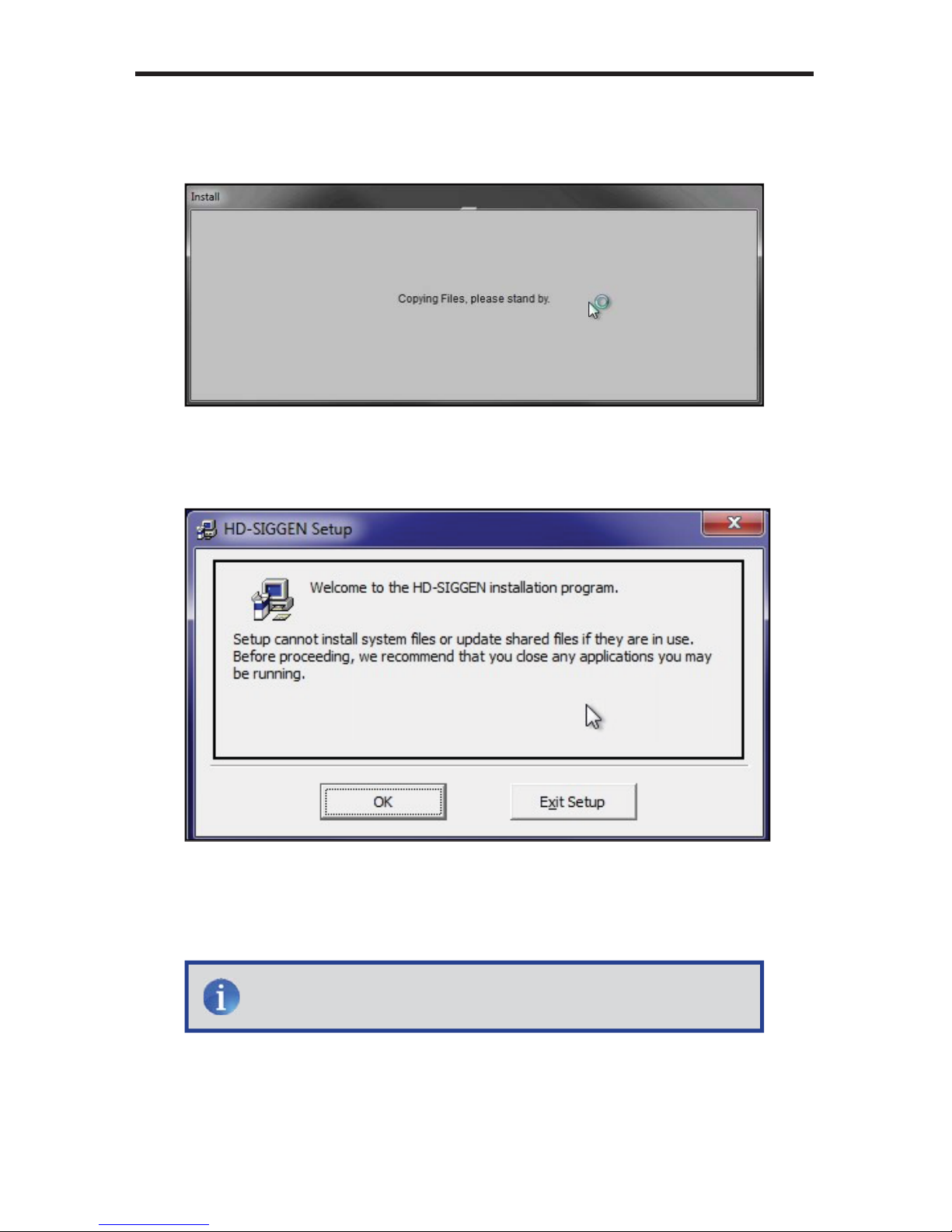
2
4. The installer will begin by copying the required installation fi les, to the hard
riv
e:
. After the required fi les have been copied to the hard drive, the installer Wel-
ome screen will appear
:
lick the OK button to continue with the installation.
lick the Exit Setup button to exit the installer.
HD PATTERN SIGNAL GENERATOR SOFTWAR
E
NOTE
:
If the installer is cancelled, the installer will remove the fi les
that were copied, earlier in the installation process.
Page 49

HD PATTERN SIGNAL GENERATOR SOFTWAR
E
. The destination directory can be changed. The default installation directory
r Windows 7® i
s
:\Program Files(x86)\HD-SIGGE
N
For other ver-
ions of the Windows® operating system, the default installation location will
:\Program Files\HD-SIGGE
N
7. During the installation process, the following message will be displayed
:
lick to install to th
e
default director
y
lick to change th
e
default director
y
Page 50
HD PATTERN SIGNAL GENERATOR SOFTWAR
E
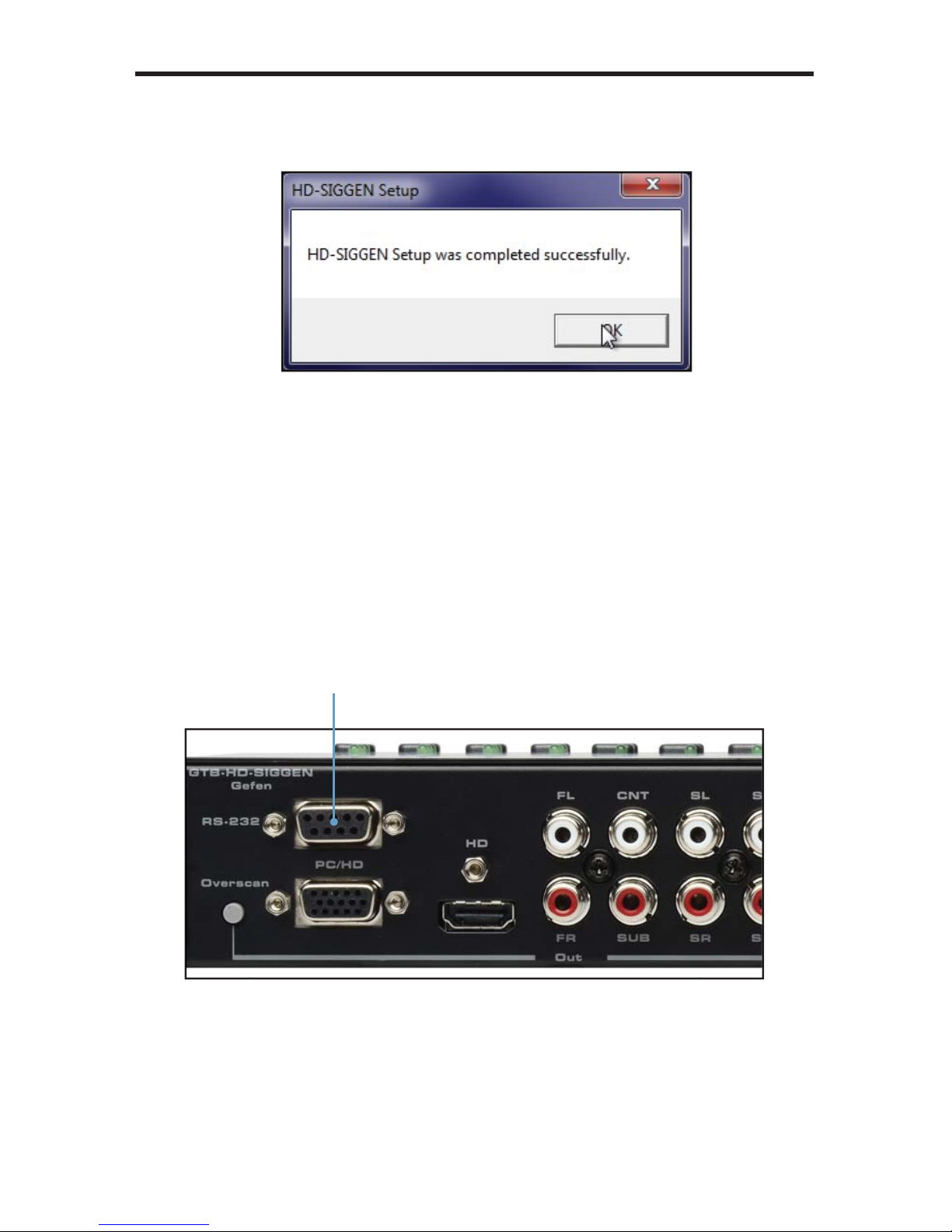
. After the installer has successfully completed the installation process, the
ollowing message box will be displayed
:
lick the OK button to dismiss the message box and exit the installer.
Connecting the RS-232 cabl
e
Before launching the HD Pattern Signal Generator software, an RS-232 cable
ust be connected from the back of the HD Pattern Signal Generator to th
e
omputer which has the HD Pattern Signal Generator software installed.
-232 port on th
e
k of the HD Pattern
ignal Generator
Page 51

5
HD PATTERN SIGNAL GENERATOR SOFTWAR
E
Running the HD Pattern Signal Generator Softwar
e
1. Launch the HD Pattern Signal Generator Software by clicking on th
e
application icon in the Windows® Start Menu
:
The example below, shows the HD-SIGGEN application icon as it appears in
the Windows 7® Start Menu
:
Page 52

HD PATTERN SIGNAL GENERATOR SOFTWAR
E
After the HD Pattern Signal Generator is launched, the following screen will be
displayed
:
2.
elect the COM port from the pull-down list. COM port 1 is selected b
y
lt.
.
lick the Connect button to initialize the connection between the software
and the HD Pattern Signal Generator.
If you are unable to connect to the HD Pattern Signal Generator, make sure that
the correct COM port is selected in the software. The Disconnect button will turn
ed if the connection between the software and the HD Pattern Signal Generator
nnot be established.
The Connect button will
turn green to indicate a
l connecti
on
The Di
sconnect butto
n
will turn red to indicate
connection.
elects the COM por
t
Page 53

7
HD PATTERN SIGNAL GENERATOR SOFTWAR
E
Selecting the Timin
g
se the Timing Select button to select the timing / resolution of the output
ignal.
2. Press the
S
ET button to set the timing.
lick the SET butto
n
to enable the timin
g
trieves the current
ettings
elect the timin
g
in the Timings window
NOTE
:
After changing a timing, pattern, the output format, or
toggling HDCP, make sure to press the Refresh button on the left
ide of the window. The HD-SIGGEN Status window is no
t
automatically updated, even if a change has been made throu
gh
the software or using the front panel. Clicking the Refresh button
will retrieve the current settings from the HD Pattern Signal
enerator. Otherwise HD-SIGGEN Status window will displa
y
Link Error”.
Page 54

HD PATTERN SIGNAL GENERATOR SOFTWAR
E
Selecting the Pattern
1.
se the Pattern Select button to select the desired pattern.
2. Press the
S
ET button to enable the pattern.
lick the SET butto
n
to enable the patter
n
A “Link Error” message caused by the Refresh
button not being pressed after connecting to th
e
D Pattern Signal Generator. Click Refresh to
pdate the information.
elect the patter
n
in the Patterns window
Page 55

9
HD PATTERN SIGNAL GENERATOR SOFTWAR
E
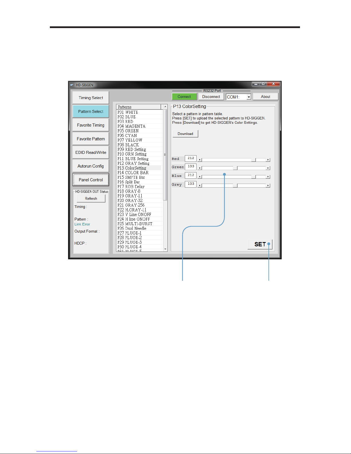
nique Patterns
Pattern 13 (ColorSetting) and Pattern 41 (Motion) can be selected from the top
anel buttons on the HD Pattern Signal Generator. However, they provide addi-
tion parameters which can onl
y
be modifi ed using the HD-SIGGEN software.
Color Settin
g
1.
elect the ColorSetting pattern (P13).
2. Press the Download button to retrieve current color settings of th
e
olorSetting pattern.
lick the Download
tton to retrieve th
e
urrent color settings
Page 56
50
HD PATTERN SIGNAL GENERATOR SOFTWAR
E
. Adjust the Red, Green, Blue, and Grey sliders to render the desired color.
4. Press the SET button to upload the current settings to the ColorSettin
g
attern.
lick the SET butto
n
to upload the new
olor settings
se the sliders to
adjust the color
Page 57

5
1
HD PATTERN SIGNAL GENERATOR SOFTWAR
E
nique Patterns
Pattern 13 (ColorSetting) and Pattern 41 (Motion) can be selected from the top
anel buttons on the HD Pattern Signal Generator. However, they provide addi-
tion parameters which can onl
y
be modifi ed using the HD-SIGGEN software.
otion
1.
elect the Motion pattern (P41).
2. Press the Download button to retrieve current color settings of th
e
otion pattern.
By default, the Motion pattern uses a block shape for the pattern.
lick the Download
tton to retrieve the
rrent Motion
attern settings
Page 58

52
HD PATTERN SIGNAL GENERATOR SOFTWAR
E
. A custom string, up to 12 characters in length, can be entered in the Custom
tring fi eld.
4.
lick the Upload button to update the HD Pattern Signal Generator with the
ew pattern.
.
lick the SET button to save the existing settings to the Motion pattern.
A
custo
m
message can be
her
e
A custom message
n be
added here
se the sliders to
adjust the color
Page 59

5
3
HD PATTERN SIGNAL GENERATOR SOFTWAR
E
Favorite Timin
g
A list of favorite timings can be assembled and stored in the HD Pattern Sig-
al Generator. The [FAV] button, on the front panel, can then be used to cycle
throu
g
h the list of timings that is created.
1. In the Timings window, place a check mark in the boxes of the timings to be
to the Favorites list.
se the Check All button to select all the timings in the Timings window. Use
the Check None button to deselect any or all currently selected timings.
2. Press the SET button to upload the selected Timings to the HD Patter
n
ignal Generator. The list of Favorite will be available using the [FAV]
button on the front panel of the HD Pattern Signal Generator.
se the Download button to download and edit the Favorite timings on the
D Pattern Signal Generator.
Place a check mark b
y
the timings to be added
to Favorit
es
Pr
ess
this button t
o
download (and edit) the
rrent Favorite li
st
Page 60

5
4
HD PATTERN SIGNAL GENERATOR SOFTWAR
E
Favorite Pattern
A list of favorite patterns can be assembled and stored in the HD Pattern Signal
enerator. The [FAV] button, on the front panel, can then be used to cycle
throu
g
h the pattern list that is created.
In the Patterns window, place a check mark in the boxes, next to the timings to
added to
the Favorites list.
se the Check All button to select all the timings in the Patterns window. Use the
heck None button to deselect any or all selected patterns.
1. Press the SET button to upload the selected Patterns to the HD Pattern
ignal Generator. The list of Favorite will be available using the [FAV] button
on the front panel of the HD Pattern Signal Generator.
se the Download button to download and edit the Favorite patterns on the
D Pattern Signal Generator.
Pl
ace a chec
k mark
by the patterns to be
to the Favorit
es
Pr
ess
this button t
o
download (and edit) the
rrent Favorite li
st
Page 61

55
HD PATTERN SIGNAL GENERATOR SOFTWAR
E
ource selection
tton
s
DID Read / Writ
e
The HD Pattern Signal Generator has the ability to read EDID data. EDID data
an also be saved, loaded, written, erased, compared, interpreted, and summed.
Each o
f
these features will be covered in this section. Clicking the EDID Read /
Write button will display the following screen
:
Reading EDI
D
1.
elect the Source by clicking one of the three radio buttons at the top portion
the screen.
EDID can be read from a downstream sink (display, etc) or from the EDID
tored in the HD Pattern Signal Generator. Click HDMI/DVI Out or VGA Out
to read the downstream EDID.
C
lick the HDMI / DVI In radio button to read
the EDID stored in the HD Pattern
Sig
nal Generator.
Page 62

5
6
HD PATTERN SIGNAL GENERATOR SOFTWAR
E
In this example, the EDID is being read from the display connected to the HD
Pattern Signal Generator
.
lick the READ button on the READ Panel.
The READ and
CO
MP (compare) functions are only available under the
EAD panel. The Pre-F, OPEN, WRITE, VERIFY, AUTO, and ERA
SE
unction are only available under the WRITE panel.
The TRANS, SUM, SAVE, and CLEAR functions are availabl
e
nder both the WRITE and READ panels.
EAD PanelWRITE Panel
EAD butt
on
NOTE
:
Disabled buttons, under the WRITE or READ panel, will
become active when EDID data is loaded into the associated panel.
Page 63

57
2. If the EDID is read successfully, the EDID will appear in the READ Panel
:
ranslating the EDI
D
After the EDID has been read, it can be translated into verbose form by clicking
the TRANS (Translate) button in the READ panel
:
HD PATTERN SIGNAL GENERATOR SOFTWAR
E
lick the TRAN
S
button to display the
EDID in ver
bose fo
rm
Page 64

5
8
HD PATTERN SIGNAL GENERATOR SOFTWAR
E
The Translate [Read] EDID screen
:
licking on the one of the items in the panel on the left, will display th
e
information in the panel on the right. Some items will have a [+] symbol next to
them, indicating that additional information is available for that section
:
Page 65

59
lick the [+] button to expand any section where additional information is
resent. In the example below, the [+] button has changed to a [-] symbol after
the
S
tandard Timings section has been expanded
:
The information about the Standard Timing 1, Standard Timing 2, and Standard
Timing 3 is listed in the panel on the right.
enerating an EDID Repor
t
licking the Report button can be used to save the verbose form of the EDID to
fi l
e:
HD PATTERN SIGNAL GENERATOR SOFTWAR
E
lick the Report button
to view a complete listing
the EDID
Page 66

60
The EDID Report window is shown below. Click the Save button to save the fi le
in .TXT format. Click the Exit button to return to the Translate EDID screen.
HD PATTERN SIGNAL GENERATOR SOFTWAR
E
Page 67

6
1
HD PATTERN SIGNAL GENERATOR SOFTWAR
E
enerating the EDID Checksu
m
nce an EDID has been read or loaded into the HD Pattern Signal Generator, a
hecksum can be generated.
1.
ead or load an EDID fi le into the HD Pattern Signal Generator.
2.
lick the SUM button under the READ panel.
lick the SUM butto
n
to generate the EDID
hecksum
Page 68
62
HD PATTERN SIGNAL GENERATOR SOFTWAR
E
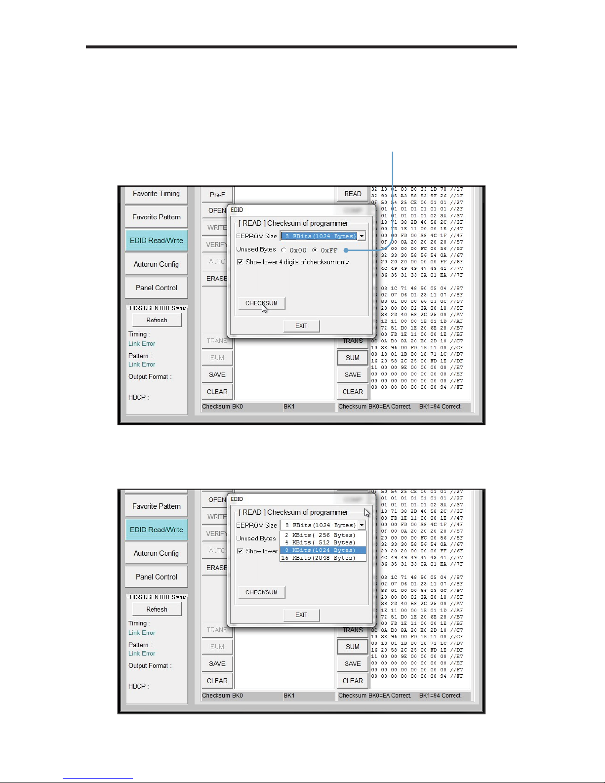
. The EDID Checksum dialog will be displayed. Select the method of how
nused bytes will be calculated into the checksum by clicking either the 0x00
or
0
xFF radio button.
4. Ad
j
ust the EEPROM size, if necessary, by selecting it from the EEPROM
ize drop-down list: 256, 512, 1024, or 2048 bytes.
elect how unused bytes
will be used in calculatin
g
the checksum
Page 69

6
3
HD PATTERN SIGNAL GENERATOR SOFTWAR
E
.
lick the CHECKSUM button to generate the EDID checksum.
B
y
default, the checksum will be restricted to the lower 4 digits. This feature
an be disabled unchecking the
bo
x.
In the example above, if the checksum were calculated by disabling the
f
eature, the result would be 0x33600.
ncheck to disable
truncation of checksum
Page 70

6
4
HD PATTERN SIGNAL GENERATOR SOFTWAR
E
Saving an EDID to a Fil
e
Any EDID can be saved to a fi le, once it has been read into the HD Patter
n
ignal Generator.
1.
nce an EDID has been read, click the SAVE button.
lick the SAVE butto
n
to save the EDID to
a
le.
Page 71
65
HD PATTERN SIGNAL GENERATOR SOFTWAR
E
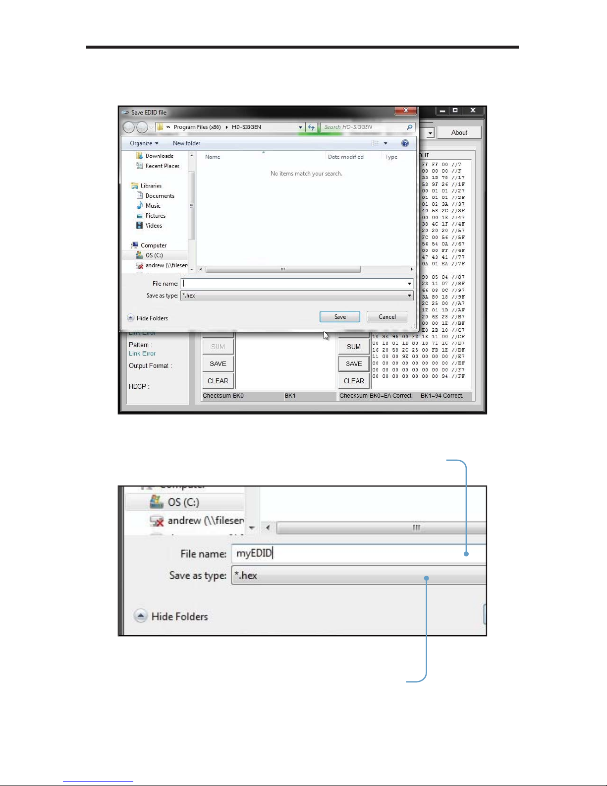
2. The Save EDID fi le dialog box will be displayed
:
.
elect a name for the EDID fi le and t
y
pe it in the File nam
e
box.
The fi le can be saved as either a .hex fi le or a .bin fi le.
elect the fi le type from the
ave as type pull-down list.
Page 72
6
6
HD PATTERN SIGNAL GENERATOR SOFTWAR
E
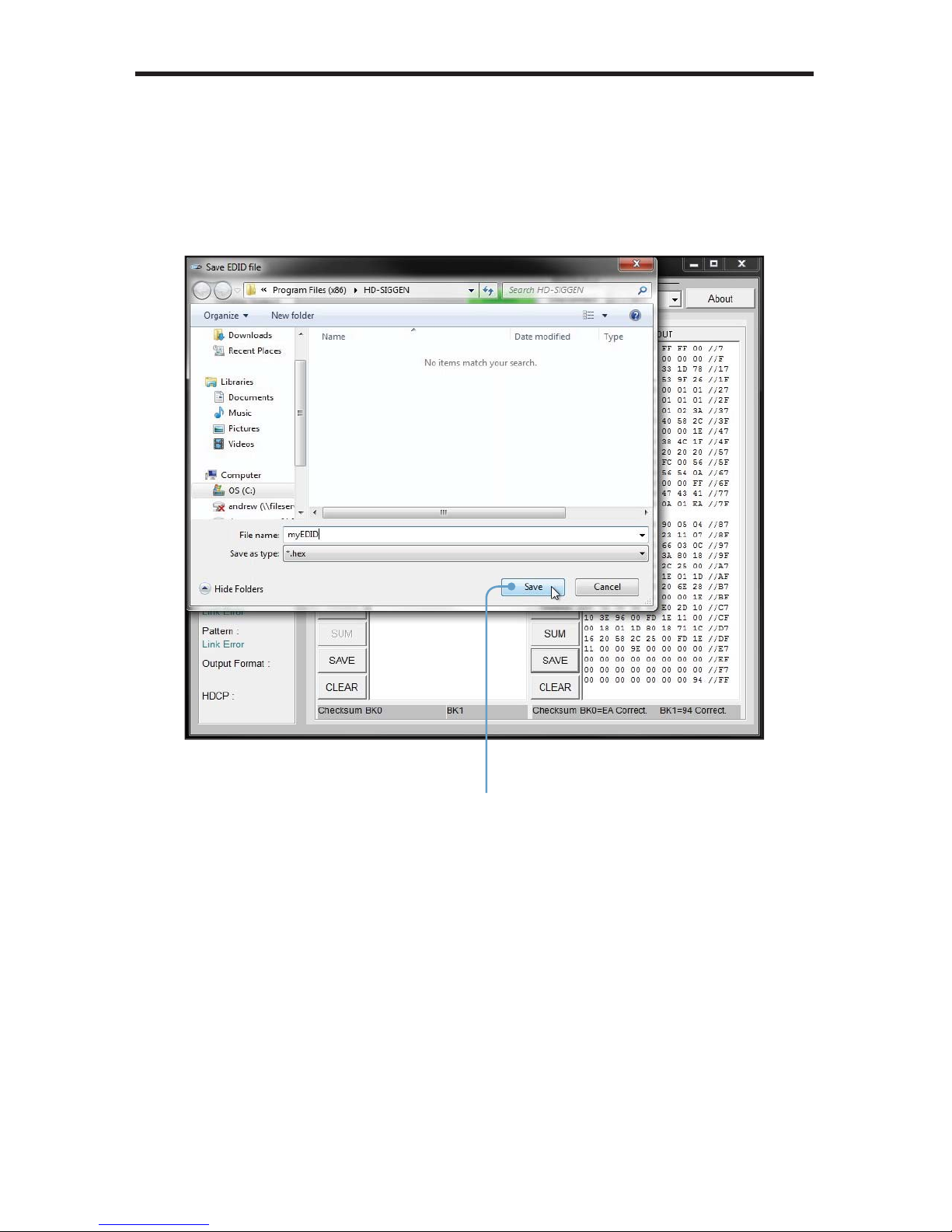
4.
elect the directory where the EDID fi le will be saved and click the Sav
e
button on the dialog box.
B
y
default, the EDID fi le will be saved in the working directory of the HD
Pattern
Sig
nal Generator software directory.
lick to save the EDID
Page 73

67
HD PATTERN SIGNAL GENERATOR SOFTWAR
E
Clearing the EDID from Memor
y
lick the Clear button to clear the EDID from memory.
I
f
an EDID is loaded (OPEN) under the WRITE panel, use the CLEAR button
to clear it from memory.
lears the EDID from
Page 74

6
8
oading an EDID from a Fil
e
An EDID fi le in binary (.bin) format or in text format (.hex) can be loaded into the
D Pattern Signal Generator.
1.
lick the OPEN button under the WRITE panel. If necessary, refer to page
1 on how to save an EDID to a fi le.
2.
elect the EDID fi le to be opened.
HD PATTERN SIGNAL GENERATOR SOFTWAR
E
lick to open an EDID fi l
e
Page 75

69
HD PATTERN SIGNAL GENERATOR SOFTWAR
E
. The EDID fi le will be loaded into the HD Pattern Signal Generator and dis-
layed in the WRITE panel.
In the example below, an EDID has been read usin
g
the HD Pattern Sig-
al Generator software (using the READ function) and an EDID has been
oaded from a fi le using the OPEN function.
Page 76

70
HD PATTERN SIGNAL GENERATOR SOFTWAR
E
Comparing EDID Dat
a
The HD Pattern Signal Generator software can compare two EDID data
tructures. One EDID is read from a sink (display, A/V receiver, etc) and the
other is loaded into the HD Pattern
Sig
nal Generator software using the OPEN
nction.
1.
ead the source EDID by following the instructions starting on page 52.
2. Load an EDID into the HD Pattern Signal Generator by following th
e
instructions starting on page 65.
.
lick the COMP button under the READ panel.
lick the COMP button
to compare the two
EDID data structur
es
Page 77
7
1
HD PATTERN SIGNAL GENERATOR SOFTWAR
E
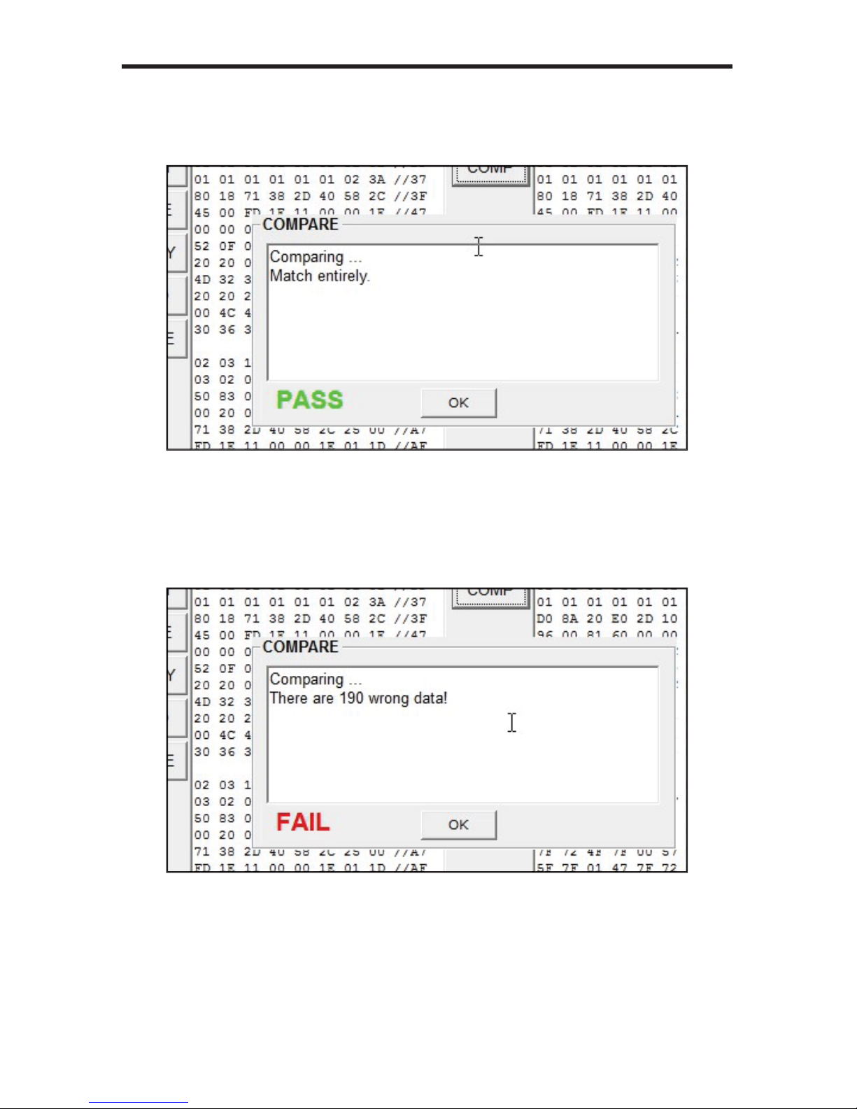
If the two EDID data structures are identical, then a message will be displayed
indicating that the compare process has passed
:
lick the OK button to return to the EDID Read / Write screen.
If there are differences in the two EDID data structures, then the compare pro-
ess will fail. The number of reported comparison errors will also be displayed.
lick the OK button to return to the EDID Read / Write screen.
Page 78

72
HD PATTERN SIGNAL GENERATOR SOFTWAR
E
Writing EDID to a Sink
After an EDID has been read from another source or loaded from a fi le, the
EDID can be written to the sink connected to the output o
f
the HD Pattern Signal
enerator.
1. Load an EDID into the HD Pattern Signal Generator by following th
e
instructions starting on page 65.
2.
lick the WRITE button to write the EDID to the sink device.
lick to write the EDID
ta to the sink devi
ce
WARNING:
verwriting the EDID of a sink device may cause
nwanted results. Be sure to save a copy of the EDID. This will
allow the sink’s EDID to be restored if necessary. Also note that
t all device EDID data structures can be overwritten. If the sink
annot be programmed with a new EDID, the WRITE process will
fa
il.
Page 79
7
3
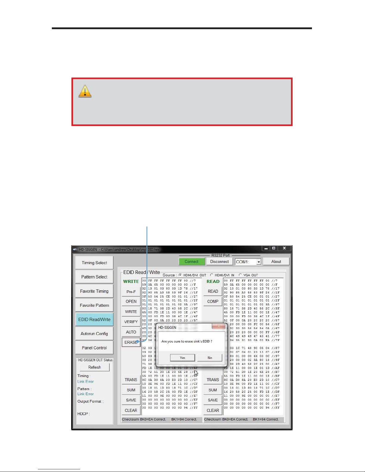
rasing the EDID from a Sink
The ERASE function will erase the EDID of a sink device.
1.
ake sure that the sink device is connected to the HD Pattern Signal
enerator.
2.
lick the ERASE button.
. The HD Pattern Signal Generator software will prompt you before erasing
the sink’s EDID. Click the Yes button to continue with the erasure. Click No
to return to the EDID Read / Write screen.
HD PATTERN SIGNAL GENERATOR SOFTWAR
E
lick to eras
e
the sink’s EDID
WARNING: Be sure to save a cop
y of
the sink’s EDID before
erforming the ERASE function. This will allow the sink’s EDID to
be restored if necessary. Also note that not all device EDID data
tructures can be erased. If the sink’s EDID cannot be erased, then
the ERASE procedure will fail.
Page 80

7
4
HD PATTERN SIGNAL GENERATOR SOFTWAR
E
Opening Recent EDID Files
The HD Pattern Signal Generator software keeps a record of the last ten fi les
which were opened or saved. To access the most recentl
y
used fi les, do th
e
ollowin
g:
1.
lick the Pre-F button in the WRITE panel.
2. A list of the most recently used EDID fi les will appear in a drop-dow
n
window.
.
ighlight and click the EDID fi le to be loaded.
The Pre-F button quickl
y
the most
ecently used EDID fi les
Page 81
75
HD PATTERN SIGNAL GENERATOR SOFTWAR
E
Autorun
onfi guration lis
t
ploads current
Autorun li
st
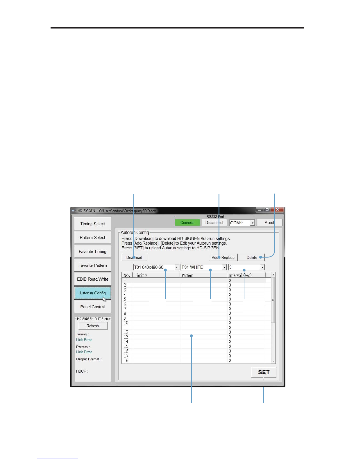
Autorun Confi guration
The Autorun Confi guration option allows custom programming of timings and
atterns used by the Autorun Demonstration mode (pressing the AUTO button on
the
f
ront panel
):
1.
lick the Autorun Confi g button.
2. If necessary, you can press the Download button to read the current Autorun
ettings from the HD Pattern Signal Generator.
.
elect the Timing and/or Pattern from the timing drop-down list boxes.
4.
elect the Duration (in seconds), from the interval drop-down box.
.
lick the Add / Replace button to add the current timing and pattern to the
Autorun Confi guration list.
Tim
ing
lecti
on
Patter
nlection
Durati
on
lect
ion
Adds or replaces the
urrent timing / pattern
Downl
oads curre
nt
Autorun li
st
Deletes a timing /
attern from lis
t
Page 82

7
6
HD PATTERN SIGNAL GENERATOR SOFTWAR
E
An existing timing and pattern set can be replaced by clicking (highlighting)
the set, selecting the new timing and new pattern from the drop-down list
boxes, then pressin
g
the Add / Replace button.
se the Delete button to remove a timing / pattern set from the Autorun
onfi guration llist.
.
lick the SET button to write the changes to the HD Pattern Signal
enerator.
anel Control
The Panel Control screen allows remote control of the front panel buttons on the
D Pattern Signal Generator. The current settings will be indicated by gree
n
ttons.
The Download button is used to retrieve the current settings from the HD Pattern
ignal Generator.
Downl
oads curre
nt
Autorun li
st
Page 83
77
HD PATTERN SIGNAL GENERATOR SOFTWAR
E
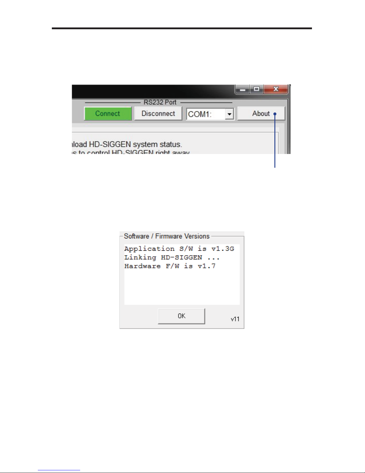
etting the Hardware and Firmware Version
Press About button on the top portion of the HD Pattern Signal Generator
tware.
The About screen will be displa
y
ed, showing the software and fi rmwar
e
version
s:
2. Press the OK button to dismiss the About box and return to the HD Pattern
ignal Generator software window.
Press to display
rdware and
software
informati
on
Page 84

7
8
RS-232 CONTROL
g
Bits per second ............................................................................................ 19200
Data bits ...............................................................................................................
8
Parity ............................................................................................................. Non
e
top bits ................................................................................................................
1
Flow Control .................................................................................................. Non
e
54321
9876
12345
6789
Only Pins 2 (RX), 3 (TX), and 5 (Ground) are used on the RS-232 serial interface
NOTE: The return value will be displayed when using a terminalbased application, indicating the current value after executing th
e
mmand.
Page 85

79
RS-232 COMMAND
S
Commands
Command
escription
A
SC001
Audio source is from external L
/R
A
SC002
Audio source is from external OPTICA
L
A
SC003
Audio source is from internal Sinewav
e
A
SC999
uery
audio source status
AT
O000
et Autorun
Off
AT
O001
et Autorun
On
AT
O999
uery Autorun Action stat
us
ATNnnn Autorun Number, nnn = 001 ~ 032
(
see note 2 on page 81
)
ATTnnn Autorun Timin
g
, nnn = 001 ~ 03
9
ATPnnn Autorun Pattern, nnn = 001 ~ 05
0
ATInnn Autorun time Interval, nnn = 005 ~ 600
(
seconds
)
AT
S999
uery Autorun Confi guration status
RRnnn
et the Red (Cr) ColorSetting value, nnn = 000 ~ 25
5
RGnnn
et the Green (Y) ColorSetting value, nnn = 000 ~ 25
5
RBnnn
et the Blue (Cb) ColorSetting value, nnn = 000 ~ 25
5
RYnnn
et the Gray ColorSetting value, nnn = 000 ~ 25
5
RR
999
uery Red (Cr) ColorSetting status (see note 3 on page 81
)
R
G999
uery Green (Y) ColorSetting status
RB
999
uery Blue (Cb) ColorSetting status
RY
999
uery Gray ColorSetting status
et color space to RGB:444
et color space to YUV:444
et color space to YUV:42
2
uery color space status
DEE
001
et deep color to 8-bi
t
DEE
002
et deep color to 10-bi
t
DEE
003
et deep color to 12-bi
t
DEE
999
uery deep color status
E
SC001
EDID source is from Tx (HDMI / DVI Out
)
E
SC002
EDID source is from Rx (built-in active EDID
)
E
SC003
EDID source is from Rx1 (built-in EDID1
)
E
SC00
4 EDID source is
f
rom Rx2 (built-in EDID2
)
Page 86

0
RS-232 COMMAND
S
Command
escription
E
SC005
EDID source is from Rx3 (built-in EDID3
)
E
SC006
EDID source is from VGA (PC / HD out
)
ERD
001
ead EDID from sink (see note 4 on page 81
)
ER
S001
Erase sink’s EDID and fi ll all bytes with FF (see note 5 on
age 81
)
EWR
001
Write EDID to sink (see note 6 on page 81
)
FAV
000
et My Favorite OFF
FAV
001
et My Favorite
ON
FAV
999
uery My Favorite action status
FP+nnn Add Pattern to Favorites, nnn = 001 ~ 05
0
FP-nnn Drop Pattern
f
rom Favorites, nnn = 001 ~ 05
0
FP+
999
uery Favorite Pattern status
(
FP-
999
can also be used
)
FT+nnn Add Timin
g
to Favorites, nnn = 001 ~ 03
9
FT-nnn Drop Timin
g f
rom Favorites, nnn = 001 ~ 03
9
FT+
999
uery Favorite Timing status
(
FT-
999
can also be used
)
D
C000
et HDCP OFF
D
C001
et HDCP
ON
D
C999
uery HDCP status
T
001
et custom string for Pattern 46 (see note 7 on page 81
)
T
999
uery string from Pattern 46
T
001
elect output format [PC]
T
002
elect output format [HD]
T
003
elect output format [DVI]
T004
elect output format [HDMI]
T
999
uery output format status
ATnnn
elect Pattern, nnn = 001 ~ 05
0
AT
999
uery Pattern status
M
001
et PCM 2
CH
M
002
et PCM 5.1
CH
M
003
et PCM 7.1
CH
M
999
uery PCM status
T
001
eset Signal Generator
IMnnn
elect Timing, nnn = 001 ~ 03
9
IM
999
uery Timing status
ER
999
uery fi rmware versio
n
Page 87

RS-232 COMMAND
S
Notes
After the RS-232 device sends commands to the HD Pattern Signal
enerator, the RS-232 device must wait for the HD Pattern Signal Generator
to responds. Althou
g
h the RS-232 device can send another command
without waiting for a response, the communication may fail if the HD Pattern
ignal Generator is in Auto mode.
2. To confi gure the HD Pattern Signal Generator to follow a sequence of
ommands in Auto mode, the following syntax is used:
xxx +
ATT
xxx
ATP
xxx +
ATI
xxx..
.
. If the HD Pattern Signal Generator is not set to Pattern 47, running a query
or the ColorSetting pattern will return:
RR
300,
CRG
300,
CRB
300
or
RY
300
4. After sending the
RD
001
response, the HD Pattern Signal Generator reads
the sink’s EDID and transmits the data to the remote terminal. If the EDID
annot be read, then the HD Pattern Signal Generator sends
xF
E
an
d
tops the datastream. The HD Pattern Signal Generator supports a 256-
byte EDID (block0 + block1).
. After sending the
R
S001
response, the HD Pattern Signal Generator
rases the sink’s EDID and fi lls all bytes with
After the EDID is erased,
the HD Pattern Signal Generator returns
R
S002
If the process fails, then
R
S003
is returned.
. After sending the
WR
001
response, the HD Pattern Signal Generator waits
or the EDID datastream (256 bytes) from the RS-232 device. After receiving
the datastream, the HD Pattern Signal Generator writes the EDID to the sink.
If the write-process is successful, then
WR
002
is returned. If the write-
rocess fails, then
WR
003
is returned.
7.
end
T
001
and wait for th
e
T
001
response from the HD Pattern Signal
enerator. Send the custom string and wait for the
T
002
response. The
maximum length for a string is 12 bytes. Any unused bytes must be fi lled
with
x
00
Only English characters are supported.
Page 88
2
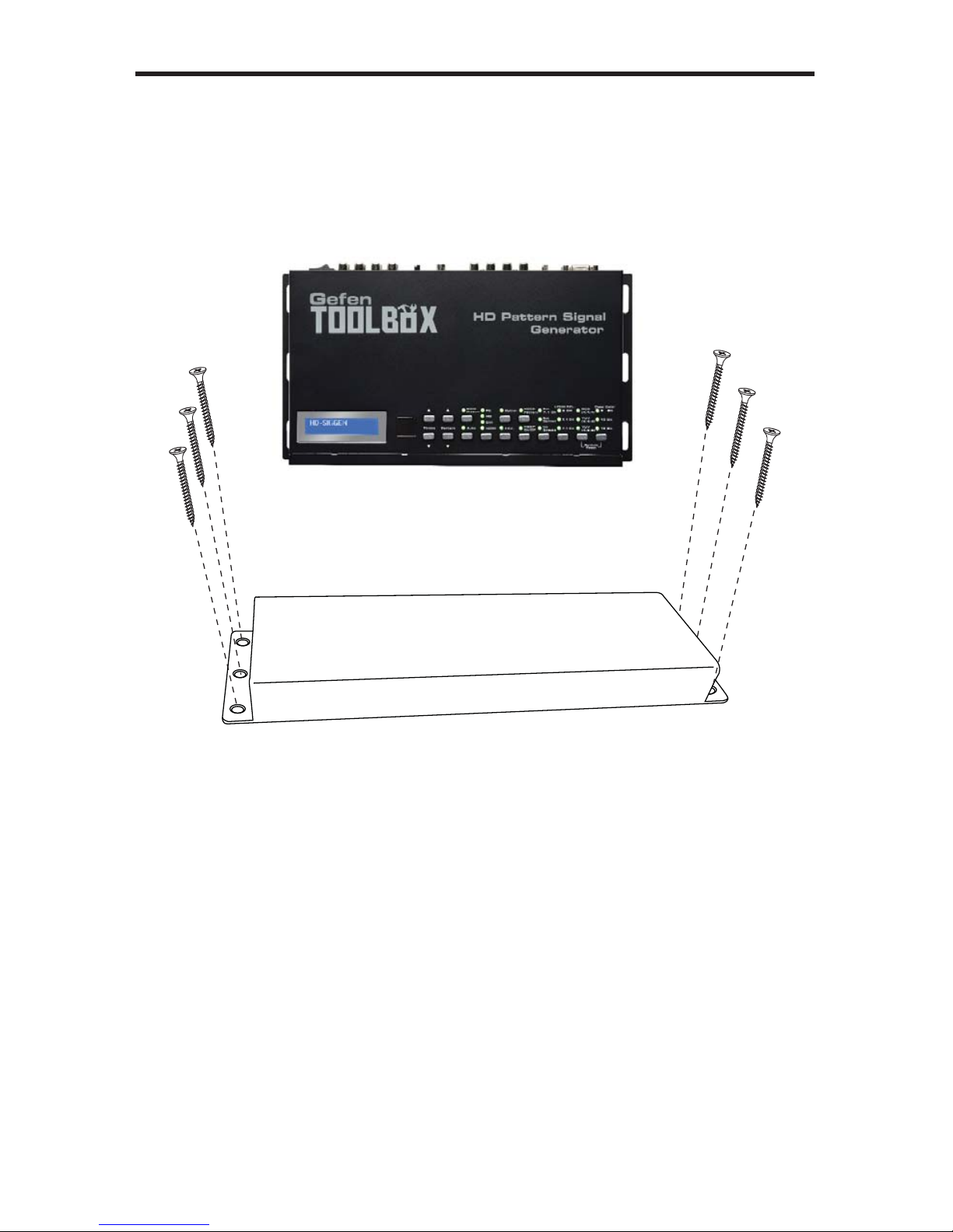
WALL MOUNTING INSTRUCTION
S
The GefenToolBox HD Pattern Signal Generator should be mounted vertically in
a wall or cabinet with wood/drywall screws as shown in the diagram above. There
hould be an inch or two of clearance between the edges of the unit and an
y
walls or vertical surfaces to allow for enough clearance for insertion and removal
cables o
n the
back of
the unit.
For installation on a drywall surface, use a #6 drywall screw. It is recommended
when installing on a drywall surface that studs be used to secure the Splitter
hould undue stress be applied when connecting and disconnecting HDMI
les.
Page 89

SPECIFICATION
S
aximum Pixel Clock............................................................................... 165 MH
z
Input Video Signal .................................................................................... 1.2V p-p
Input DD
C Sig
nal ............................................................................... 5V p-p (TTL)
Video Input........................................................... (1) HDMI Type A ,19-pin, femal
e
Video Output....................................................... (1) HDMI, Type A, 19-pin, femal
e
Video Output.................................................................................(1) HD15, femal
e
Analog Audio Inputs...................... FL, FR, C, LFE, SL, SR, SSL, SSR (RCA type
)
Analog Audio Outputs....................FL, FR, C, LFE, SL, SR, SSL, SSR (RCA type
)
Digital Audio Input................................................................................ (1) TOSLin
k
Digital Audio Outputs........................................................ (1) TOSLink, (1) S/PDIF
Input Impedance............................................................................................ 10 k
Ω
Frequency Response..................................................... 20 Hz - 20 kHz (± 0.5 dB
)
NR.............................................................................................................> 90 dB
THD.......................................................................... < 0.001% at 1 kHz or 2 V rms
rosstalk..................................................................................................... > 90 dB
-232 Serial Port............................................................................. DB-9, femal
e
Power Supply .............................................................................................. 5V DC
Power Consumption ............................................................................ 10W (max.
)
perating Temperature ............................................................................ 0 - 40
°C
Dimensions ................................................................... 12.0” W x 1.75” H x 6.5” D
hipping Weight ............................................................................................ 6 lbs.
Page 90

efen warrants the equipment it manufactures to be free from defects in material
and workmanship.
I
f
equipment fails because of such defects and Gefen is notifi ed within two (2)
ears from the date of shipment, Gefen will, at its option, repair or replace the
quipment, provided that the equipment has not been subjected to mechanical,
lectrical, or other abuse or modifi cations. Equipment that fails under conditions
other than those covered will be repaired at the current price of parts and labor in
ect at the time of repair. Such repairs are warranted for ninety (90) days from
the day of reshipment to the Buyer.
This warranty is in lieu of all other warranties expressed or implied, including
without limitation, any implied warranty or merchantability or fi tness for any
articular purpose, all of which are expressly disclaimed.
1. Proof of sale may be required in order to claim warranty.
2.
ustomers outside the US are responsible for shipping charges to and from
efen.
.
opper cables are limited to a 30 day warranty and cables must be in their
original condition.
The information in this manual has been carefully checked and is believed to
be accurate. However, Gefen assumes no responsibility for any inaccuracies
that may be contained in this manual. In no event will Gefen be liable for
direct, indirect, special, incidental, or consequential damages resulting from
any defect or omission in this manual, even if advised of the possibility of such
damages. The technical information contained herein regarding the features and
pecifi cations is subject to change without notice.
For the latest warranty coverage information, refer to the Warranty and Return
Policy under the Support section of the Gefen Web site at www.gefen.com.
RODUCT REGISTRATIO
N
lease register your product online by visiting the Register Product page
nder the Support section of the Gefen Web site
.
Page 91

Page 92

Rev A
6
Pb
This product uses UL or CE listed power supplies.
Nordhoff St., Chatsworth CA 9131
1
1-
800-545-6900
818-772-9100 fax: 818-772-912
0
w
ww.gefentoolbox.com support@gefentoolbox.co
m
 Loading...