

Page 1
®
A
///////
V
r
I
T-
C
MA
AA
ual
Cinema Scale
ro
I
r Man
Page 2

ASKING FOR ASSISTANC
E
t
0
0
0
:
ST
:
C
e
0600
1
e
A
f Gef
C
G
on
f
d
2
echnical Suppor
Telephone (818) 772-910
(800) 545-690
Fax (818) 772-912
echnical Support Hours
:00 AM to 5:00 PM Monday thru Friday P
Write To
efen, LL
o Customer Servic
2
Nordhoff St
hatsworth, CA 9131
www.gefen.com
upport@gefen.com
Notic
efen, LLC reserves the right to make changes in the hard ware, packaging and
any accompanying doc u men ta tion without prior written notice.
/V Cinema Scaler Pro I is a trademark o
ANALO
anufactured under license from Dolby Laboratories.
Dolby”, “Pro Logic”, and the double-D symbol are trademarks o
Dolby Laboratories.
2010 Gefen, LLC, All Rights Reserve
All trademarks are the property of their respective companies
Versi
en, LL
Rev E
Page 3

CONTENT
S
t
D
p
y
g
e
t
t
p
1 Introduction
Operation Notes
Features
Panel Layou
5 Panel Descriptions
6 Panel Descriptions
7 Front Panel Buttons
7 Navigation
7 Input Selection
Using The A/V Cinema Scaler Pro - Main LC
LCD Screen
10 A/V Cinema Scaler Pro - Initial Startu
10 Powering On
12 A/V Cinema Scaler Pro - Main Screen
12 Main Displa
13 Input Resolutions
14 Audio Input Type
14 Audio Formats
15 Sampling Rates
15 Number Of Channels
15 Output Screen
16 Surround Processin
17 Dynamic Range Compression
17 Reference Level Compensation
18 DVI Output Type
18 HDMI EDID Type
19 Audio Input Typ
0 Product Title
1 A/V Cinema Scaler Pro - Confi guration
1 Main Features Menu
2 A/V Cinema Scaler Pro - Picture Adjus
3 Mode
4 Contrast
5 Brightness
5 Hue
5 Saturation
6 Sharpness
6 Aspect Ratio
8 Noise Reduction
9 Horizontal Position
9 Vertical Position
9 Clock
0 Phase
0 Exit Picture Adjust
0 A/V Cinema Scaler Pro - Color Adjus
1 Color Tem
2 Red
3 Green
Page 4

t
t
t
y
y
t
e
e
e
t
e
y
CONTENT
S
3 Blue
3 Exit Color Adjus
4 A/V Cinema Scaler Pro - Lipsync Delay Adjus
4 Lipsync Delay
4 Exit Lipsync Adjust
5 A/V Cinema Scaler Pro - Surround Delay Adjus
5 Surround Right Delay
6 Rear Surround Right Dela
6 Rear Surround Left Dela
6 Exit Lipsync Adjust
7 A/V Cinema Scaler Pro - Output Selection
7 Output Timing 1080P
8 Output Timing 2K
8 Exit Output Selection
8 A/V Cinema Scaler Pro - On Screen Display Adjus
9 Horizontal Position
0 Vertical Position
0 Timeout
0 Background
1 Exit OSD Adjust
1 A/V Cinema Scaler Pro - Firmwar
2 DB-25 Audio Input & Bypass Mod
2 A/V Cinema Scaler Pro - DB-25 Audio Bypass Mod
2 Enabling Bypass Mode
3 Analog Input And Output Pinou
4 Analog DB-25 Output
4 Analog DB-25 Input
5 RS-232 Serial Control Interfac
5 RS-232 Settings
6 RS-232 Serial Control Commands
8 Rack Mount / Tabletop Installation
9 Specifi cations
52 Warrant
Page 5

g
o
(OSD)
INTRODUCTIO
N
ongratulations on your purchase of the A/V Cinema Scaler Pro. Your complete
atisfaction is very important to us.
efen
Gefen delivers innovative, pro
that harness integration, extension, distribution and conversion technologies.
efen’s reliable, plug-and-play products supplement cross-platform computer
stems, professional audio/video environments and HDTV systems of all sizes
with hard-working solutions that are easy to implement and simple to operate.
he Gefen A/V Cinema Scaler Pr
The Gefen Cinema Scaler is a video and audio device that can accomplish a
nique variety of video scaling and audio conversion tasks. Any signal can be
caled and displayed with total end user control. An On-screen display
and full featured settings allow you to fi ne-tune your viewing experience and get
the most out of your current A/V setup.
How It Works
imply connect your analog or digital A/V sources to the Gefen Cinema Scaler.
sing the OSD menu system and controls, select your desired input and
esolution, audio processing needs, and other adjustments. The Cinema Scaler
will brilliantly scale your image to your digital cinema projector or DVI /HDMI
display.
Note: This unit is fully HDCP compliant.
ressive computer and electronics add-on solutions
Page 6

g
t
6 C
t
6 C
z
A
g
)
00/60Hz
)
z
00/60Hz
080/60Hz
:
)
)
)
:
)
t
OPERATION NOTE
S
READ THESE NOTES BEFORE INSTALLING OR
OPERATING THE A/V CINEMA SCALER PRO
• Audio from the analog DB-25 input is available in bypass mode only. No
video will be output when usin
• Audio connection for each input is selectable between analog and digital.
election of the audio input type is selectable using the front panel LCD
menu system. For more information please see page 18.
• Coaxial/Optical Digital Audio Format Suppor
2 Channel LPCM: 32kHz – 96kHz
ulti-Channel AC-3 1-
• HDMI Digital Audio Format Suppor
2 Channel LPCM 32kHz – 96kHz
ulti-Channel AC-3 1-
Channel LPCM 32kHz - 96kH
•
udio Processin
Dolby Pro Logic II *All analog/digital (No DB-25) inputs.
ee page 16 for a detailed description of this feature
•
aximum supported video input formats
the bypass mode.
hannels Bitstream
hannels Bitstream
DVI-D: Maximum resolution 1920x12
DVI-I: Maximum resolution 1920x1200/60Hz (both analog and digital
omponent: Maximum resolution 1920x1080/60H
VGA: Maximum resolution 1920x12
DMI: Maximum resolution 1920x1
•Supported video output formats
Digital: 1920x1080p 24/50/60Hz and 2K (2048x1080p 24/50/60Hz
Analog: 1920x1080p 24/50/60Hz and 2K (2048x1080p 24/50/60Hz
23.97/24/50/60Hz passthrough is supported via all inputs. (Detailed timings
an be found on page 13
•Supported audio output formats
Analog: 8 channel discrete (balanced over DB-25
•
his product is fully HDCP complian
Page 7

g
t
t
)
)
gh
n
o
t
y
FEATURE
S
Features
• 1 DVI-I video + analog or digital audio inputs
• 1 DVI-D video + analo
• 2 Component video + analog or digital audio inputs
• VGA + analog or digital audio inpu
•
DMI inpu
• DB-25 analog audio input (7.1 discrete, balanced
•
upport resolutions of 1920x1080p 60Hz and 2048x1080p 60Hz
•
electable digital or analog audio input for each source (except HDMI
• Front panel source selection with “bypass” mode for DB-25 pass-throu
•
• LCD screen for scaling preferences & audio settings
• Audio delay for precise video synchronizatio
•
• Floating balanced audio outputs with separate power supply for avoiding
-232 for optional fi rmware updates/external control
apable of “black barring”/stretching 4:3 aspect rati
round loop issues.
ackage Includes
1) Cinema Scaler Pro I uni
1) 12V DC Power Suppl
1) Set of Rack Ears
1) User’s Manual
or digital audio inputs
Page 8
3
1
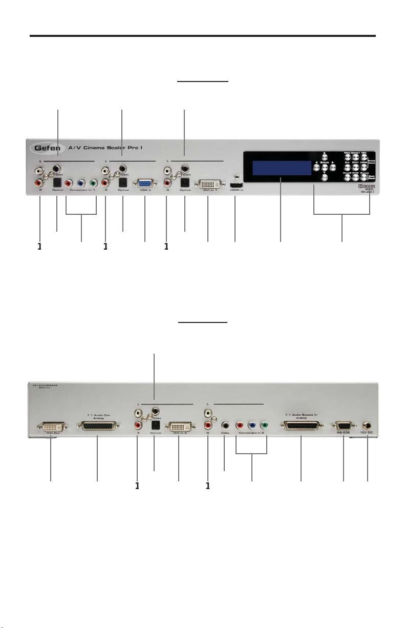
ANEL LAYOU
T
Front Panel
10
5
Back Panel
12
7
1
14151
Page 9

t
t
t
t
t
y
s
ANEL DESCRIPTION
S
Analog L+R RCA Audio Inpu
This input will accept 2 channel analog audio using 1 pair of RCA analog audio
type connectors. There is a set of connectors available for all inputs except for
the HDMI and DB-25 inputs. For a listing of accepted audio formats please see
age 14.
Digital Optical Audio Input (TOSLINK)
This input will accept multi-channel digital audio using 1 optical type connector.
There is a connector available for all inputs except for the HDMI, Component 2,
and DB-25 inputs. For a listing of accepted audio formats, including supported
audio channels, please see page 14-15.
omponent Video Inpu
This input will accept component video (YPbPr) via 3 RCA type connectors.
There is one set of connectors located on the front and back panels. For a listing
of accepted resolutions please see page 13.
Digital Coaxial Audio Input (S/PDIF)
This input will accept multi-channel digital audio using 1 RCA type connector.
There is a connector available for all inputs except for the HDMI and DB-25
inputs. For a listing of accepted audio formats, including supported audio
hannels, please see page 14-15.
GA V ideo Inpu
This input will accept VGA video (RGBHV) via a HD-15 type connector. For a
isting of accepted resolutions please see page 13.
DVI-I Video Inpu
This input will accept DVI-I video (RGB analog or digital) via a DVI-I type
onnector. Input format is automatically determined. For a listing of accepted
esolutions please see page 13.
HDMI Inpu
This input will accept an HDMI (RGB,YCbCr) signal via an HDMI type A
onnector. Audio and video are both supported by this connector. For a listing of
accepted resolutions and audio formats please see page 13.
High Contrast LCD Displa
This display will show pertinent information for confi guration control and status.
For information on how to use this display please see page 12-19.
avigation and Input Selection Button
These buttons are used to select the desired input source. Navigation buttons
are also provided for easy user navigation and confi guration of features. Please
ee page 7 for more information.
5
Page 10

ANEL DESCRIPTION
S
t
t
t
t
DVI-D Outpu
This input will accept DVI-D (RGB digital) capable display device via a DVI-I
type connector. This output port will support displays that are capable of
accepting the two output resolutions; 1080p and 2K.
7.1 Channel Analog Audio Outpu
This output will accept a DB-25 type connector to connect to a multi-channel
analog audio device. This port is always active. All audio from each input will be
onverted and output through this port. For pin-out information please see page
42-43.
2 DVI-D Inpu
This input will accept DVI-D video (digital) via a DVI-I type connector. Input
ormat is digital only. For a listing of accepted resolutions please see page 13.
7.1 Channel Analog Audio Inpu
This input will accept a DB-25 type connector for multi-channel analog audio
input. This port is only active when the bypass mode is selected (page 41). For
in-out information please see page 42-43.
S-232 Serial Control Interface
This port is used for serial communication for multiple functions. Access to
ertain features are only through the RS-232 interface.
2V DC Power Receptacle
This port will accept power via the included 12V DC power supply. This is a
ocking type connector.
Page 11
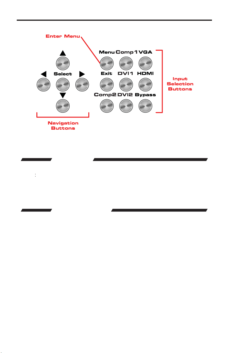
FRONT PANEL BUTTON
S
►▼
butto
used to confi
fi g
fi g
The front panel buttons are used for navigation, confi guration, and input selection.
The directional buttons (▲
n is
The
enu button is used to enter the con
The
xit button is used to exit the con
The desired input port can be directly selected using the front panel input buttons.
imply press the desired input button. Source changing can take up to 10 seconds
longer when syncing digital video signals).
The bypass button will enable bypass mode (page 41).
are used to navigate the user menus system. The
rm menu and item selections.
uration menu .
uration menu at any time.
7
Page 12

CONNECTING AND OPERATING THE A/V CINEMA SCALER PRO
O
f
:
I
)
C
t
)
C
t
:
bedded audio
C
C
e
g
n
f
g
NSTALLING THE A/V CINEMA SCALER PR
onnect video source devices to the A/V Cinema Scaler Pro’s video inputs.
ollowing inputs are available
The
Front Panel
HDM
DVI-I (analog and digital DVI
VGA
omponen
Back Panel
DVI-D (digital DVI
omponen
NOTE:
2.
onnect audio sources to the A/V Cinema Scaler Pro’s audio inputs. The
ollowing inputs are available
Front Panel
DMI: Em
DVI-I: Analog RCA L+R or Digital TOSLINK or S/PDIF
omponent: Analog RCA L+R or Digital TOSLINK or S/PDIF
VGA: Analog RCA L+R or Digital TOSLINK or S/PDIF
Back Panel
DVI-D: Analog RCA L+R or Digital TOSLINK or S/PDIF
omponent: Analog RCA L+R or Digital S/PDIF
DB-25: Analog multi-channel audio. Please se
pa
NOTE: All inputs, except
audio sources. Therefore, each input has a selector option in the OSD that will
allow the user to choose which type of audio is used.
.
onnect the DVI capable output device to the A/V Cinema Scaler Pro’s DVI-I
input.
NOTE: This output is a DVI-I connector. Analo
be output through this connector. Selection of the output format can be
accomplished by using either the OSD (on-screen display) or the front panel
LCD and buttons. Please see page 17 for instructions on how to change the DVI
output type.
4.
onnect the analog DB-25 audio output to the analog DB-25 input on the
appropriate audio device.
.
onnect the included 12V power supply between the A/V Cinema Scaler Pro
and an open power socket. Ensure that the input cable is properly secured
to the unit.
e 42-43 for specifi c pin-out informatio
or HDMI, is able to accept both analog and digital
or digital type video can
Page 13
SING THE A/V CINEMA SCALER PRO - MAIN LC
D
O
(
D
e
y
A/V CINEMA SCALER PRO - NAVIGATION
The A/V Cinema Scaler Pro uses a series of buttons, located on the front panel,
or all input selection and feature functions. All status information, such as
the input and output resolutions, are always available on the front panel
Screen
be navigated and adjusted by referencing either the
All menu navigation and adjustments are accomplished by using the front panel
buttons. Please review the front panel buttons below.
User adjustable features, such as color correction and aspect ratio, can
Screen or the
creen Display
OS
.
D
n-
For a full description of each of these buttons please see the descriptions on
age 7.
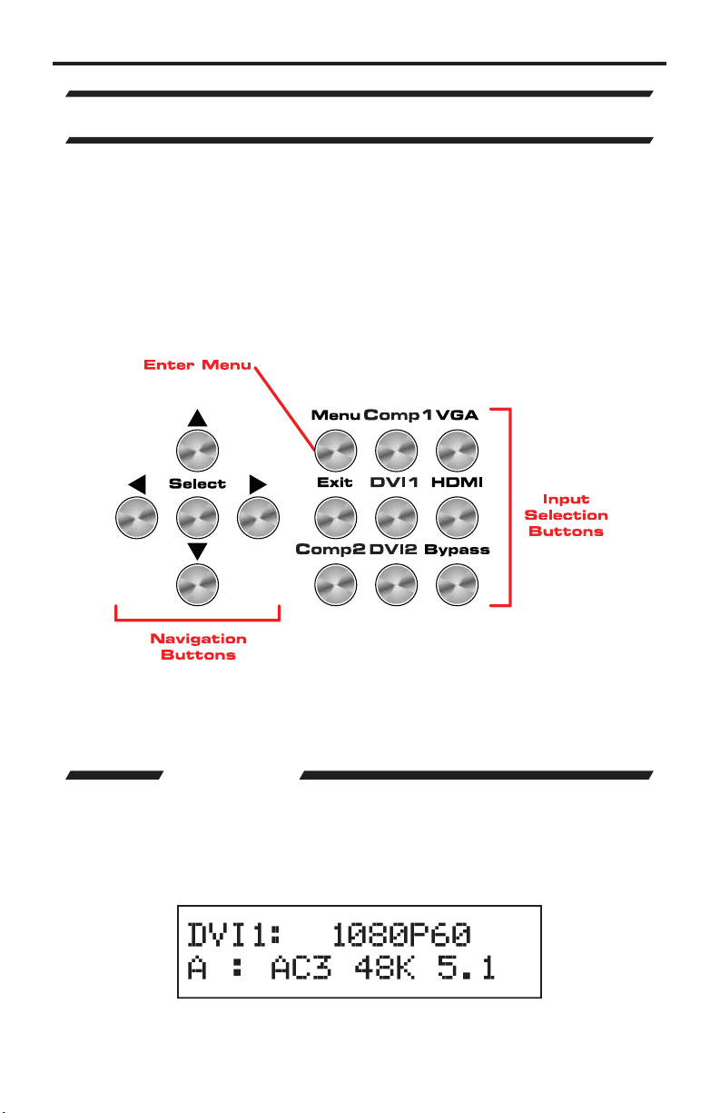
Th
CD Screen displa
and adjust functions on the A/V Cinema Scaler Pro. This display is a high
ontrast 2-line/16-character LCD. It will display information like in the example
low.
ain Screen
s status information and can also be used to navigate
Page 14

SING THE A/V CINEMA SCALER PRO - MAIN LC
D
P
:
ese are
e
e
A
e
A/V CINEMA SCALER PRO - INITIAL STARTU
nce all video and audio connections have been made and the power supply
as been connected, the A/V Cinema Scaler Pro should automatically turn on.
The front panel LCD should indicate this by displaying the text
roduct Titl
This screen should be displayed for 3 seconds while the system is booting. Once
this is complete, the
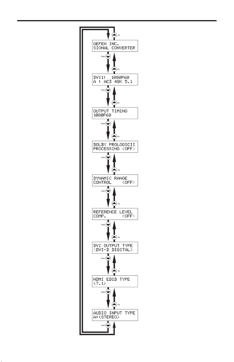
There are 7 different information panes that are available to provide the user with
l information. Th
Surround Processing, DVI Output Type, HDMI EDID Type, and Audio Input
p
information panes. Please use the
different information panes. The cycling order is displayed on the next page.
ain Screen should appear.
the
roduct Titleain Screen
and
Output Screen,
buttons to cycle through the
NOTE: Th
lected.
udio Input Type pane will not be available when the HDMI input is
10
Page 15
1
SING THE A/V CINEMA SCALER PRO - MAIN LC
D
e
p
roduct Titl
ain Screen
Output Screen
Surround Processing Screen
namic Range Control Screen
Reference Level Com
Screen
VI Output Type Screen
HDMI EDID Type Screen
Audio Input Type Screen
ensation
1
Page 16
SING THE A/V CINEMA SCALER PRO - MAIN LC
D
y
effec
ease see below fo
:
y
e
t
1
t
1
C
o
G
/
1
I
1
2
t
2
2
2
A/V CINEMA SCALER PRO - MAIN SCREEN
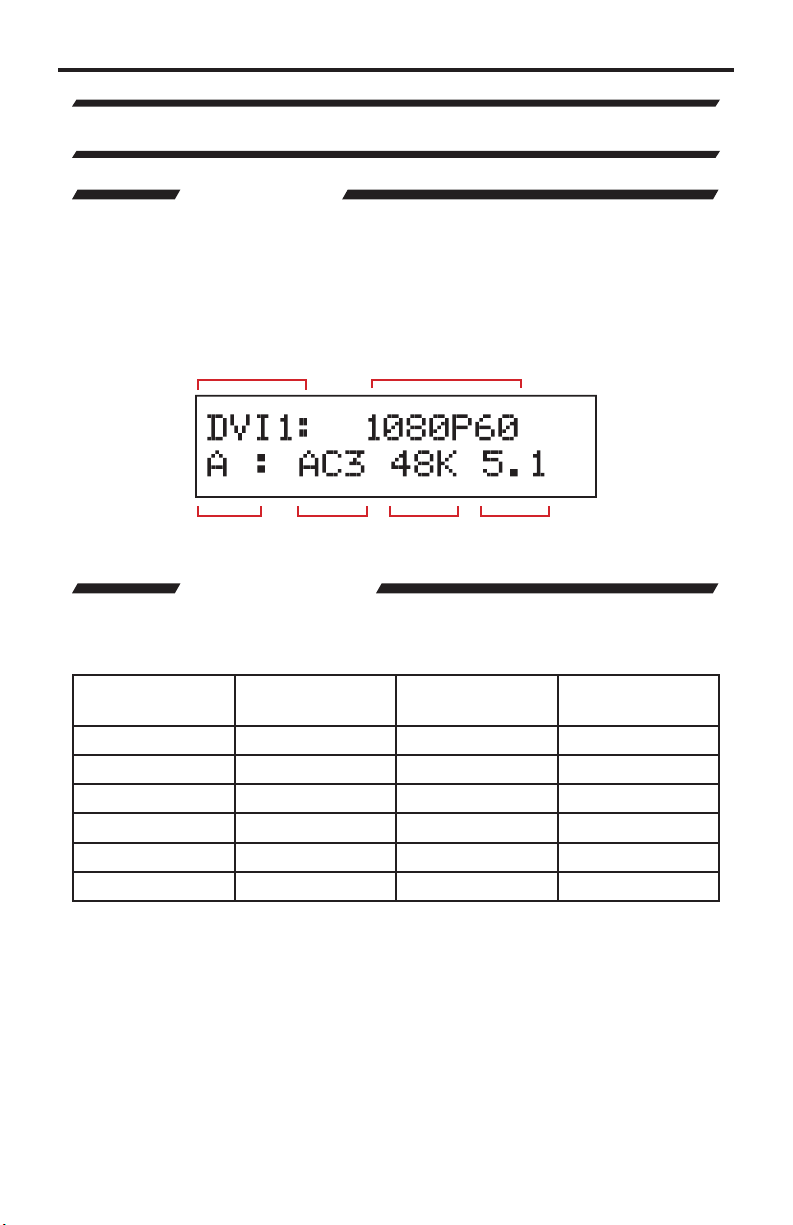
The
ain Screen will displa
urrently selected input port and audio input format. The currently used output
ormat can also be displayed by pressing the
ttons while on this screen will have no
Screen
ayout.
useful information to the user. It displays the
button. Pressing the ◄ or ►
t. Pl
r the
ain
Selected Input
Input Audio
Type
Audio
Format
Input Resolution
Sampling
Rate
Number of
Channels
ain Screen
This portion of the screen will display the currently selected input. The available
inputs, labels, and associated buttons are listed below
CD Displa
Nam
DVI-D1
DVI-D
MP
P
DVI-A
DMI
MP
Actual Inpu
omponen
AFr
DVI-
ocation
Front Panel
nt PanelV
Front Panel DVI
DMI Front Panel
omponen
Back Panel
DVI-D Back Panel DVI
Front Panel
Button
MP
A
DMI
MP
12
Page 17
3
SING THE A/V CINEMA SCALER PRO - MAIN LC
D
f
t
t
y
t
/p
z
/p
p
z
/p
/30/50/59.97/60Hz
)
V
)
)
GA (
)
z1152x86
)
80x960
)
GA (
)
)
GA (
)
(
g
)
V
GA (
)
)
GA (
)
z1152x86
)
80x960
)
)
)
)
&
&
/p
z
/p
p
z
/p
/30/50/59
/60Hz
/24/50/
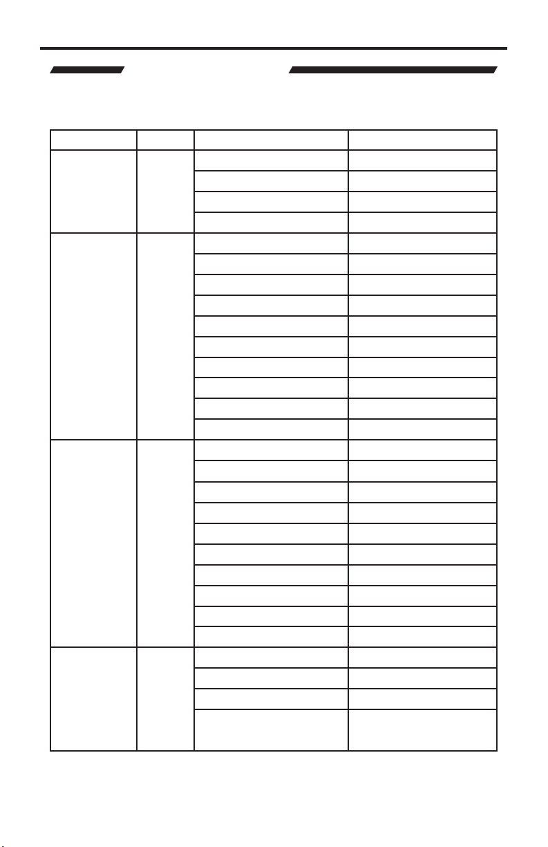
This portion of the screen will display the currently selected input’s resolution.
The acceptable resolutions
or each input type are listed below.
Inpu
omponen
PC (VGA
DVI-I
analo
and digital
DVI-D
DVI-I
Digital Only)
DMI
Forma
YPbPr
BH
BH
B
B
or YCbCr
Resolution Frequenc
480i
76i
720
1080i
VGA (640x480
VGA (800x600
1024x768
X
4
XGA (1280x1024
12
WXGA (1280x800
1360x768
WX
XGA (1600x1200
WUX
WUXGA (1920x1200
1920x1200
640x480
V
VGA (800x600
1024x768
X
4
XGA (1280x1024
12
WXGA (1280x800
WXGA (1360x768
XGA (1600x1200
480i
76i
720
1080i
25/29.97
23.97/24/25/29.97
H
Hz
H
Hz
Hz
60H
Hz
Hz
Hz
Hz
Hz
Hz
Hz
Hz
Hz
60H
Hz
Hz
Hz
Hz
Hz
Hz
Hz
H
Hz
H
.
7
NOTE: 23.97
be applied.
60Hz signal are pass-through. No framerate conversions will
1
Page 18
4
SING THE A/V CINEMA SCALER PRO - MAIN LC
D
AUDIO INPUT TYPE
g
t
e
)
1
)
(S/
)/(TOS
)
g (
)
(S/
)/(TOS
)
1
)
(S/
)/(TOS
)
I
(S/
)
2
)
g
(S/
)
2
)
(S/
)/(TOS
)
AUDIO FORMATS
t
e
1
)
o
(S/
)/(TOS
)
)
g (
)
o
(S/
)/(TOS
)
)
1
)
o
(S/
)/(TOS
)
)
I
(S/
)
)
2
)
o
(S/
)
)
)
o
(S/
)/(TOS
)
)
.
This portion of the screen will display the currently selected input’s audio type. All
inputs, except for HDMI, will accept both an analog and digital type audio signals.
The user can choose which type of audio is selected by usin
pe
Each input’s audio type, except for HDMI, can be user selected. This
is not available in bypass mode.
the Audio Input
Inpu
MP
A
DVI
DM
MP
DVI
Audio Input Typ
Analog (L+R RCA
Digital
Analo
Digital
PDIF
PDIF
LINK
L+R RCA
LINK
Analog (L+R RCA
Digital
PDIF
Digital
LINK
PDIF
Analog (L+R RCA
ital
Di
PDIF
Analog (L+R RCA
Digital
PDIF
LINK
CD Display (Audio Type
A
D
A
D
A
D
D
A
D
A
D
This portion of the screen will display the currently selected input’s audio format.
When the input’s audio type selector switch is set to analog, the display will only
ead “Stereo”; Sampling rate and number of channels will not be displayed. This
does not cover the bypass mode.
Inpu
MP
A
DVI
Audio Input Typ
Analog (L+R RCA
Digital
Analo
Digital
PDIF
PDIF
LINK
L+R RCA
LINK
Analog (L+R RCA
Digital
PDIF
LINK
Supported Audio Formats
tere
PCM / (Dolby Digital
tere
PCM / (Dolby Digital
tere
PCM / (Dolby Digital
DM
MP
DVI
olby, Pro Logic, and the double-D symbol are trademarks of Dolby Laboratories
Digital
PDIF
Analog (L+R RCA
Digital
PDIF
Analog (L+R RCA
Digital
PDIF
LINK
PCM / (Dolby Digital
tere
PCM / (Dolby Digital
tere
PCM / (Dolby Digital
1
Page 19

SING THE A/V CINEMA SCALER PRO - MAIN LC
D
t
e
1
(S/
)
G
g
(S/
)
1
(S/
)
2
(S/
)
2
(S/
)
t
e
1
(S/
)
2
)
g
(S/
)
2
)
1
(S/
)
2
)
8
)
2
(S/
)
2
)
2
(S/
)
2
)
e
y
e
p
.
This portion of the screen will display the currently selected input’s audio
ampling rate. This will only display information when the input audio type is
digital. This does not cover the bypass mode.
Inpu
MP
ADi
V
DVI
DMI Embedded Digital
MP
DVI
Audio Input Typ
Digital
Digital
Digital
Digital
ital
PDIF
PDIF
PDIF
PDIF
PDIF
Supported Sampling Rates
2KHz-96KHz
2KHz-96KHz
2KHz-96KHz
2KHz-96KHz
2KHz-96KHz
2KHz-96KHz
This portion of the screen will display the number of audio channels that are
being used by the currently selected input. This will only display information when
the input audio type is digital. This does not cover the bypass mode.
Inpu
MP
VGADi
DVI
Audio Input Typ
Digital
Digital
ital
PDIF
PDIF
PDIF
DMI Embedded Digital
MP
DVI
Digital
Digital
olby, Pro Logic, and the double-D symbol are trademarks of Dolby Laboratories
PDIF
PDIF
Supported PCM
Channels
p to
p to
p to
p to
p to
p to
upported (Dolby
Digital) Channels
p to 6 (5.1
p to 6 (5.1
p to 6 (5.1
p to 6 (5.1
p to 6 (5.1
p to 6 (5.1
Pressing the
th
Output Screen
button when th
ain Screen is displa
ed will take the user to
This screen is provided to easily determine and change the
urrent output resolution setting.
ut Screen
Out
Output Timing
15
Page 20

6
SING THE A/V CINEMA SCALER PRO - MAIN LC
D
t
080P60
080 60Hz
K
080 60Hz
f
use
e
g
use
e
f
:
This A/V Cinema Scaler Pro supports only two output resolutions
Outpu
1
2
The user has the option of changing the output resolution
Screen
Pressing the ▲button will return the
will cycle the user to the
NOTE: 1080p 24Hz is supported and will be passed throu
24Hz or 2K 24Hz depending on the selected output resolution.
This unit features Dolby Pro Logic II surround sound processing. Dolby Pro
Logic II processes any high quality stereo signal source into fi ve separate full
requency channels. Dolby Pro Logic II also decodes 5 channels from stereo
Pro Logic II.
Use the
ignals encoded in traditional four-channel Dolby Surround or fi ve-channel Dolby
Resolution
1920x1
2048x1
rom the Output
or ► buttons to immediately change the output resolution.
r to th
roduct Title
ain Screen
.
Pressing the
h as either 1080p
This screen will display the current status of the surround processing mode.
Pressing the ▲button will return the
will cycle the user to the
The user has the option of changing the processing mode
rocessing
rocessing mode on or off.
NOTE
hannel analog and digital sources.
creen. Use the ◄ or ► buttons to immediately change the
When the processing mode is set to ON, it will only have an affect on 2
VI Output Type
r to th
Output Screen
.
rom the Surround
Pressing the
1
Page 21

SING THE A/V CINEMA SCALER PRO - MAIN LC
D
C
use
e
e
C
y
C
use
g
g
C
Dynamic Range Compression (DRC) is a feature that will apply compression of
oud sounds over a certain threshold while quiet sounds remain untreated. This
eature is useful for reducing loud noises that will overpower quieter sounds.
This screen will display the current
the
r to th
to th
RLC
The user has the option of changing the
or ► buttons to immediately change the
eference Level Compensation (RLC) features attenuation that can be used to
apply a -3dB gain to the front right/left and center channels. This -3dB will be
applied when RLC is on.
This screen will displa
the
r to the
the
RC
Surround Processing
.
the current RL
VI Output Type
.
R
tate. Pressing the
creen. Pressing the
RC
tate from this screen. Use the
R
tate.
tate. Pressing the
creen. Pressing the
button will return
will cycle the user
button will return
will cycle the user to
The user has the option of changin
or ► buttons to immediately chan
the RLC
e the RL
tate from this screen. Use the
tate.
17
Page 22

8
SING THE A/V CINEMA SCALER PRO - MAIN LC
D
odes is se
g
e
use
e
e
e
e
:
s se
g.
y/
y
e
use
e
g
e
e
g
e
The DVI output is a DVI-I type which can be connected to either a digital or
analog DVI device. This option will allow the user to change the output type at
anytime. Please note that HDCP protected content will not be output when the
t to
m
VI-A Analo
This screen will display the currently selected
tton will return the
to th
HDMI EDID Type
The user has the option of changing the
the or ► buttons to immediately change the
NOTE
In accordance with HDCP regulations, protected content will not be
output via the DVI-I port when the
This option will set the supported LPCM audio channels in the EDID (displa
device information). This will allow the HDMI source device to output up 7.1
hannels of LPCM audio or limit it to 5.1 channels.
This screen will display the currentl
tton will return the
cle the user to the Audio Input Type
r to th
r to th
RLC
creen. Pressing the
.
VI Output Type i
selected HDMI EDID Typ
VI Output Type
VI Output Typ
VI Output Typ
VI Output Typ
creen. Pressing the
.
Pressing the
will cycle the user
from this screen. Use
t to
VI-A Analo
Pressing the
will
The user has the option of changin
th
or ► buttons to immediately chan
the HDMI EDID Typ
e the HDMI EDID Typ
1
from this screen. Use
Page 23

SING THE A/V CINEMA SCALER PRO - MAIN LC
D
:
AUDIO INPUT TYPE
y
e
use
e
g
e
g
e
:
NOTE
This option will simply set the supported audio formats to include either
.1 or 7.1 LPCM audio formats. The source must still be able to output these
formats for this option to have any effect.
Each input, excluding the HDMI input, supports multiple audio input types. This
option will allow the user to select the desired audio type for each input. For a
omplete listing of the supported formats for each input, please see page 14.
This screen will display the currentl
button will return the
cle the user to the
The user has the option of changin
the◄ or ► buttons to immediately chan
NOTE
This option is not available on the HDMI and Bypass inputs. The
omponent 2 input does not have an OPTICAL audio input.
r to th
roduct Title
selected Audio Input Typ
HDMI EDID Type
.
the Audio Input Typ
e the Audio Input Typ
creen. Pressing the
Pressing the
will
from this screen. Use
19
Page 24

SING THE A/V CINEMA SCALER PRO - MAIN LC
D
e
e
This screen will display the product title. Pressing the
r to th
Screen
Output Screen
Pressing the ◄ or ► buttons while on this screen will have no effect.
Pressing the
will cycle the user to the
button will return th
ain
0
Page 25

A/V CINEMA SCALER PRO - CONFIGURATIO
N
e
f
e
AIN FEATURES MENU
nce all connections have been made and a valid video input signal is detected,
ain Features Menu will become available. The
th
adjustment menus will also become available. From any of the information panes
n th
ain LCD
enu
Use the
ollowing illustrates the order of the features and the cycling order.
creen, press the
and
buttons to cycle through the
enu
tton to enter the
ollowing video/audio
ain Features
ain Features Menu
The
Page 26

A/V CINEMA SCALER PRO - CONFIGURATIO
N
:
j
y
y
f
e fi
:
y
g
f
T
t
g
enu use
e
o selec
t
or
e
f
The following are the
icture Adjust
Color Ad
ipsync Delay This menu will allow the user to appl
Surround Dela
Output Selection This menu will control which output resolution is used.
OSD Adjust This menu controls options
Firmware Th
ust
ain Features Menu items and short descriptions
ptions in this menu include preset video settings and
ser adjustable video settings. Items such as brightness,
ontrast, and sharpness are found here.
ptions in this menu control the appearance of white.
Preset settings are available, as well as a user setting with
manual control.
a lip sync delay that
is input specifi c. Settings made for one input will not affect
another input.
This menu will allow the user to apply a delay to each
individual surround channel. Right surround, left surround,
ear right surround, and rear left surroundhannel delay
adjustments can be made. These settings are global
and will affect all output audio, no matter which input is
lected.
or the on-screen display
stem. Items such as OSD-timeout and opacity are found
re.
rmware revision and build date are listed here.
NOTE
The following pages will strictly reference what the
when adjustin
ollowing sections.
options. The OSD will mirror the options and
CD Screen displa
unctions in the
A/V CINEMA SCALER PRO - PICTURE ADJUS
The
icture Adjus
that will help enhance the fi nal video output. These presets will help by tunin
the output video to compensate for different lighting and viewing environments.
Presets can be bypassed by using the
been selected all individual options become modifi able.
To enter the
Features Menu t
the menu. The following page illustrates all possible options that are available in
th
icture Adjust menu
NOTE:
menu. All adjustments in this menu are global for all inputs except Bypass Mode.
ome menu items will be input specifi c and will not appear in other input
menu will allow the user to select predefi ned picture modes
ser
icture Adjust m
t
icture Adjus
or all inputs.
etting. Once the
the and
Use the
buttons from th
Select
ser
tton to enter
etting has
ain
2
s
Page 27

A/V CINEMA SCALER PRO - CONFIGURATIO
N
ode is s
r
all individual options will be available for
g
enu for HDMI, DVI-D and
VI-I (Digital Portion) Inputs
enu for Component Inputs
enu for VGA and
VI-I (Analog Portion) Inputs
The preset picture modes are selectable with this option. Preset contrast,
brightness, hue, saturation, and sharpness settings are stored for each mode.
When the m
witched to
adjustment.
To cycle between the modes, use the
be immediate and no other buttons need to be pressed to confi rm the change.
The modes and cycle order is listed on the next page.
se
or
or Select buttons. The chan
e will
Page 28

A/V CINEMA SCALER PRO - CONFIGURATIO
N
:
g
e
V
f
ge
r
User confi gured settings
ess
or
g
g
U
The preset modes are listed below
Standard Useful for
ovi
Useful for dimly lit environments
ivid Use
se
nce the
the button to select the next option. Use the
option.
This option will set the contrast level for the output video signal.
Pr
haracter will surround the numerical value to signify that user adjustment can
be
omplete, press the Select button to save.
option. Use the
ser mode is selected, additional options will become available. Use
the or
in. Use the
and to adjust the value of this option. When adjustments are
option to return to the previous option.
eneral content
ul for accentuating colors for a more vibrant ima
option to return to the previous
Select buttons to be
in adjusting this option. A < and >
se the
button to select the next
Page 29

A/V CINEMA SCALER PRO - CONFIGURATIO
N
ess
or
g
butto
ess
or
g
butto
ess
or
g
butto
This option will set the brightness level for the output video signal.
Pr
the or
haracter will surround the numerical value to signify that user adjustment can
begin. Use the
omplete, press the Select
option. Use the ▲ option to return to the previous option.
This option will set the hue balance for the output video signal. This option will
ot be available when the VGA or DVI-I (Analog portion) input is selected.
Pr
the or
haracter will surround the numerical value to signify that user adjustment can
begin. Use the
omplete, press the Select
option. Use the ▲ option to return to the previous option.
Select buttons to be
and to adjust the value of this option. When adjustments are
tton to save.
Select buttons to be
and to adjust the value of this option. When adjustments are
tton to save.
in adjusting this option. A < and >
se the
in adjusting this option. A < and >
se the
n to select the next
n to select the next
This option will set the saturation level for the output video signal. This option will
ot be available when the VGA or DVI-I (Analog portion) input is selected.
Pr
the or
haracter will surround the numerical value to signify that user adjustment can
begin. Use the
omplete, press the Select
option. Use the ▲ option to return to the previous option.
Select buttons to be
and to adjust the value of this option. When adjustments are
tton to save.
in adjusting this option. A < and >
se the
n to select the next
5
Page 30

A/V CINEMA SCALER PRO - CONFIGURATIO
N
ess
or
g
U
ASPECT RATIO
odes to choose fro
This option will set the sharpness level for the output video signal. This option will
ot be available when the VGA or DVI-I (Analog portion) input is selected.
Pr
the or
haracter will surround the numerical value to signify that user adjustment can
begin. Use the
omplete, press the Select button to save.
option. Use the
The aspect ratio of the output video is set with this option. There are 5 aspect
tion m
Select buttons to be
and to adjust the value of this option. When adjustments are
option to return to the previous option.
m.
in adjusting this option. A < and >
se the
button to select the next
To cycle between the aspect ratio modes, use either the
buttons. The change will be immediate and no other buttons need to be pressed
to confi rm the change. The aspect ratio modes and cycle order is listed below.
or
or Select
Page 31

A/V CINEMA SCALER PRO - CONFIGURATIO
N
:
S
n
S
)
S
)
x
S
n
S
n
/
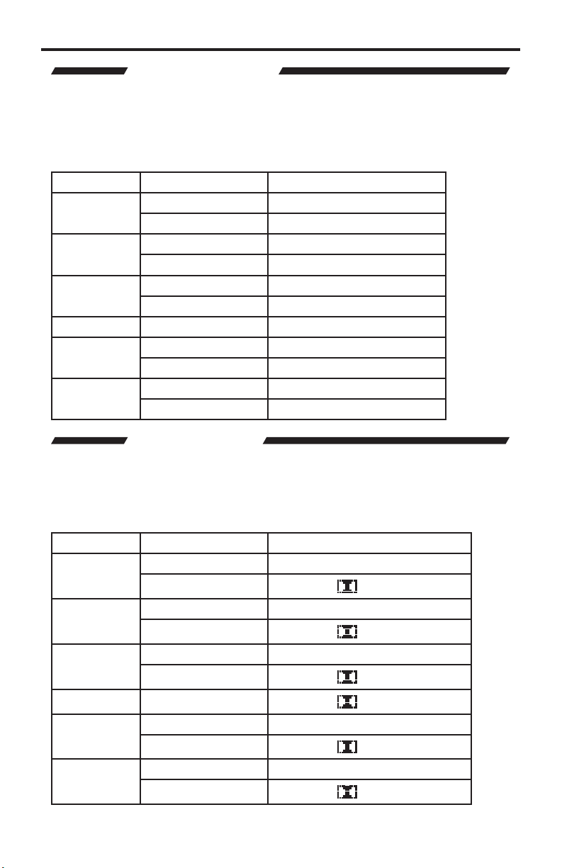
The aspect ratio modes are listed below
Full
Overscan
nderscan
etterbo
anscan
Please use the examples below do determine which aspect ratio mode should
be used. Please pay attention to the appearance of the circles. All circles
that appear as ovals will result in an output image that appears stretched
ompressed.
tretches the image to fi ll the scree
tretches the image to just beyond the border of the output
esolution (a portion of the image may be cropped
tretches the image to just within the border of the output
esolution (a black border will appear around the outside edges
tretches the image to 16:9 aspect ratio without undersca
tretches the image to 4:3 aspect ratio without undersca
7
Page 32

A/V CINEMA SCALER PRO - CONFIGURATIO
N
y
eductio
odes are
:
eductio
off
w
d
e
oderate leve
deo noise reduction
g
g
)
se the
revious option.
This option will allow the user to apply a noise reduction fi lter to the component
video input sources. This option will only be available when the input source
is component video. The noise reduction fi lter reduces noise that commonl
appears in analog video sources. There are 4 settings to choose from.
To cycle between the noise reduction settings, use either the
buttons. The change will be immediate and no other buttons need to be pressed
to confi rm the change. The aspect ratio modes and cycle order are listed below.
button to select the next option. Use the
option to return to the
or
or Select
The noise r
o
iddl
High Hi
se the
revious option.
n m
Noise r
Low level video noise reduction is applie
M
h level video noise reduction (may cause a slight ghostin
ect on objects
button to select the next option. Use the
listed below
n is
l vi
option to return to the
Page 33

A/V CINEMA SCALER PRO - CONFIGURATIO
N
g
ess
or
g
U
butto
g
ess
or
g
U
butto
ess
or
g
U
butto
This option will set the horizontal position of the video image in relation to the
output border. This option is only available when using the VGA or DVI-I (Analo
ortion) inputs.
Pr
the or
haracter will surround the numerical value to signify that user adjustment can
begin. Use the
omplete, press the Select button to save.
option. Use the ▲ option to return to the previous option.
This option will set the vertical position of the video image in relation to the
output border. This option is only available when using the VGA or DVI-I (Analo
ortion) inputs.
Pr
the or
haracter will surround the numerical value to signify that user adjustment can
begin. Use the
omplete, press the Select button to save.
option. Use the ▲ option to return to the previous option.
Select buttons to be
and to adjust the value of this option. When adjustments are
Select buttons to be
and to adjust the value of this option. When adjustments are
in adjusting this option. A < and >
se the
in adjusting this option. A < and >
se the
n to select the next
n to select the next
This option will adjust the clock timing to enable the user to adjust the video
image. This option is only available when using the VGA or DVI-I (Analog portion)
inputs.
Pr
the or
haracter will surround the numerical value to signify that user adjustment can
begin. Use the
omplete, press the Select button to save.
option. Use the ▲ option to return to the previous option.
Select buttons to be
and to adjust the value of this option. When adjustments are
in adjusting this option. A < and >
se the
n to select the next
9
Page 34

A/V CINEMA SCALER PRO - CONFIGURATIO
N
ess
or
g
g
U
g
T
e
t
e
e
enu use
e
o selec
t
or
This option will adjust the phase to enable the user to adjust the video image.
This option is only available when using the VGA or DVI-I (Analog portion) inputs.
Pr
the or
haracter will surround the numerical value to signify that user adjustment can
in. Use the
be
omplete, press the Select button to save.
option. Use the
Select buttons to be
and to adjust the value of this option. When adjustments are
option to return to the previous option.
in adjusting this option. A < and >
se the
button to select the next
This option will return the user to the
To return to the
button will cycle to the
se the ▲ option to return to the previous option.
ain Features Menu press the Select button. Pressin
ode option. Use the
ain Features Menu
the
button to select the next option.
A/V CINEMA SCALER PRO - COLOR ADJUS
Th
Color Adjus
appearance of white (color temperature). Presets can be bypassed by using
th
ser
me modifi able.
To enter th
Features Menu t
menu. The following page illustrates all possible options that are available in the
Color Adjust
menu will allow the user to select predefi ned settings for the
etting. Once the
Color Adjust m
.
ser
etting has been selected all individual options
t Color Adjus
the and
Use the
buttons from th
Select
ain
tton to enter the
0
Page 35

A/V CINEMA SCALER PRO - CONFIGURATIO
N
S
r
all individual options will be available for adjustment.
g
emode is
ed
OLOR ADJUST MENU OPTION
These Options are
only available when
th
lect
The preset color temperature modes are selectable with this option. Preset red,
reen, and blue settings are stored in each mode. When the mode is switched to
se
To cycle between the modes, use the
be immediate and no other buttons need to be pressed to confi rm the change.
The modes and cycle order is listed are listed on the following page.
or
or Select buttons. The chan
e will
Page 36

A/V CINEMA SCALER PRO - CONFIGURATIO
N
:
C
m
C
C
r
User confi gured settings
ess
or
g
g
The preset color temperature settings are listed below
Normal
War
Cool
se
nce the
the button to select the next option. Use the
option.
This option will set the amount of red in the output video signal.
Pr
the or
haracter will surround the numerical value to signify that user adjustment can
in. Use the
be
omplete, press the Select
option. Use the
olors/white will be neutral. White should not have an overly red
or blue appearance.
olors/white will have a slightly red appearance.
olors/white will have a slightly blue appearance.
ser mode is selected, additional options will become available. Use
option to return to the previous
Select buttons to be
and to adjust the value of this option. When adjustments are
tton to save. Use the
option to return to the previous option.
in adjusting this option. A < and >
button to select the next
2
Page 37

A/V CINEMA SCALER PRO - CONFIGURATIO
N
ess
or
g
U
butto
ess
or
g
U
butto
e
g
This option will set the amount of green in the output video signal.
Pr
the or
haracter will surround the numerical value to signify that user adjustment can
begin. Use the
omplete, press the Select button to save.
option. Use the ▲ option to return to the previous option.
This option will set the amount of blue in the output video signal.
Pr
the or
haracter will surround the numerical value to signify that user adjustment can
begin. Use the
omplete, press the Select button to save.
option. Use the ▲ option to return to the previous option.
Select buttons to be
and to adjust the value of this option. When adjustments are
Select buttons to be
and to adjust the value of this option. When adjustments are
in adjusting this option. A < and >
se the
in adjusting this option. A < and >
se the
n to select the next
n to select the next
This option will return the user to the
This option will return the user to the
Features Menu press the Select button. Pressin
Color Temp option.
to return to the previous option.
se the
button to select the next option. Use the
ain Features Menu
ain Features Menu
To return to th
the
button will cycle to the
ain
option
Page 38

A/V CINEMA SCALER PRO - CONFIGURATIO
N
T
y
f
use
o selec
t
or
or
y by
n
e
g
use
A/V CINEMA SCALER PRO - LIPSYNC DELAY ADJUS
The
ipsync Delay Adjust menu will allow the user to appl
ul for correcting errors in synchronization between the audio and video.
is use
This delay has a maximum correction time of 80 milliseconds. Each input can
ave a separate lip sync adjustment value. This adjustment will not affect audio
delay when in the Bypass Mode.
To enter the
ain Features Menu t
button to enter the menu. There is only one option in this menu.
This option will set the lip sync delay for the currently selected input.
ipsync Delay Adjust
t
ipsync Delay Adjus
nu
the and buttons from the
a lip sync delay that
Use the
Select
Pressing the
increments. Pressing the
maximum delay available is 80 milliseconds. Use the
xit LipSync Adjust optio
This option will return the user to the
This option will return the user to the
Features Menu press the Select button. Pressin
the
r to the
Select buttons will advance the dela
button will reduce the delay by 5 milliseconds. The
ain Features Menu
ain Features Menu
ipSync Delay option.
the
5 millisecond
or
tton to select the
To return to th
or
button will return
ain
Page 39

A/V CINEMA SCALER PRO - CONFIGURATIO
N
T
e
y
e
use
e
o selec
t
or
e
or
e
A/V CINEMA SCALER PRO - SURROUND DELAY ADJUS
Th
Surround Delay Adjust menu will allow the user to appl
ompensate for the distance between the main and surround audio channels.
Each surround delay has a maximum correction time of 150 milliseconds. The
ettings in this menu option are global and will affect the surround channels for
very input. This adjustment will not affect audio delay when in the Bypass Mode.
To enter th
ain Features Menu t
button to enter the menu. The following illustrates all possible options that are
vailable in th
Surround Delay Adjust
t Surround Delay Adjus
Surround Delay Adjust
nu
.
the
and
a delay to
buttons from th
Use the
Select
This option will set the surround delay for the surround right channel.
When this option is selected, pressing the
delay by 5 millisecond increments. Pressing the
by 5 milliseconds. The maximum delay available is 150 milliseconds. Use the
button to select the next option. Use the
Select
option to return to the previous option.
ttons will advance th
button will reduce the delay
5
Page 40

A/V CINEMA SCALER PRO - CONFIGURATIO
N
or
e
y
or
e
y
or
e
y
e
U
This option will set the surround delay for the surround left channel.
When this option is selected, pressing the
delay by 5 millisecond increments. Pressing the
by 5 milliseconds. The maximum delay available is 150 milliseconds. Use the
button to select the next option. Use the
This option will set the surround delay for the rear surround right channel.
When this option is selected, pressing the
delay by 5 millisecond increments. Pressing the
by 5 milliseconds. The maximum delay available is 150 milliseconds. Use the
button to select the next option. Use the
This option will set the surround delay for the rear surround left channel.
When this option is selected, pressing the
delay by 5 millisecond increments. Pressing the
by 5 milliseconds. The maximum delay available is 150 milliseconds. Use the
button to select the next option. Use the
Select
option to return to the previous option.
Select
option to return to the previous option.
Select
option to return to the previous option.
ttons will advance th
button will reduce the dela
ttons will advance th
button will reduce the dela
ttons will advance th
button will reduce the dela
This option will return the user to the
This option will return the user to the
Features Menu press the Select button.
option. Use the
option to return to the previous option.
ain Features Menu
ain Features Menu
se the
button to select the next
To return to th
ain
Page 41

A/V CINEMA SCALER PRO - CONFIGURATIO
N
e
e
enu use
e
o selec
or
ess
e
g
y
A/V CINEMA SCALER PRO - OUTPUT SELECTION
Th
Output Selection menu will allow the user to select the output video
lution.
To enter th
Features Menu t
the menu. The following illustrates all possible options that are available in the
Output Selection
Output Selection m
t Output Selection
.
the and buttons from th
Use the
Select
tton to enter
ain
This option will change the output resolution to a progressive 1920x1080 at 60Hz
ignal. All input formats will be scaled to this resolution.
Pr
th
Select button to set this resolution. The chan
Pressing the
button to select the next option. Use the
button will c
cle to the Output Timing 2K option.
option to return to the previous option.
e will be immediate.
se the
7
Page 42

ess
e
g
e
U
T
e
e
use
e
o selec
t
f
A/V CINEMA SCALER PRO - CONFIGURATIO
N
This option will change the output resolution to a progressive 2048x1080 at 60Hz
ignal. All input formats will be scaled to this resolution.
Pr
th
Select button to set this resolution. The chan
Pressing the
button to select the next option. Use the
button will cycle to the
xit Output Selection option.
option to return to the previous option.
e will be immediate.
se the
This option will return the user to the
This option will return the user to the
Features Menu press the Select button.
option. Use the
option to return to the previous option.
ain Features Menu
ain Features Menu
se the
button to select the next
To return to th
ain
A/V CINEMA SCALER PRO - ON SCREEN DISPLAY ADJUS
Th
On Screen Display Adjust menu will allow the user to set options related
to the on-screen display. Horizontal and vertical alignment, opacity, and time-out
ettings are found here.
To enter th
th
Select button to enter the menu. The
options that are available in the On Screen Display Adjust
On Screen Display Adjust
ain Features Menu t
nu
the
and buttons from
t On Screen Display Adjus
ollowing page illustrates all possible
Use the
.
Page 43

A/V CINEMA SCALER PRO - CONFIGURATIO
N
y.
ess
or
g
U
butto
This option will change the horizontal position of the on-screen displa
Pr
the or
haracter will surround the numerical value to signify that user adjustment can
begin. Use the
omplete, press the Select button to save.
option. Use the ▲ option to return to the previous option.
Select buttons to be
and to adjust the value of this option. When adjustments are
in adjusting this option. A < and >
se the
n to select the next
9
Page 44

ess
or
g
U
y
e
ess
or
g
U
ess
or
g
A/V CINEMA SCALER PRO - CONFIGURATIO
N
This option will change the vertical position of the on-screen display.
Pr
the or
haracter will surround the numerical value to signify that user adjustment can
begin. Use the
omplete, press the Select button to save.
option. Use the
This option will change the amount of idle time before the on-screen displa
turns to th
Pr
the or
haracter will surround the numerical value to signify that user adjustment can
begin. Use the
omplete, press the Select button to save.
option. Use the
Select buttons to be
and to adjust the value of this option. When adjustments are
option to return to the previous option.
ain Screen
Select buttons to be
and to adjust the value of this option. When adjustments are
option to return to the previous option.
in adjusting this option. A < and >
se the
in adjusting this option. A < and >
se the
button to select the next
button to select the next
This option will change the opacity level of the on-screen display.
Pr
the or
haracter will surround the numerical value to signify that user adjustment can
begin. Use the
omplete, press the Select
option. Use the
Select buttons to be
and to adjust the value of this option. When adjustments are
tton to save.
option to return to the previous option.
in adjusting this option. A < and >
se the
0
button to select the next
Page 45

A/V CINEMA SCALER PRO - CONFIGURATIO
N
e
U
E
e
y
g
This option will return the user to the
This option will return the user to the
Features Menu press the Select button.
option. Use the ▲ option to return to the previous option.
ain Features Menu
ain Features Menu
se the
button to select the next
To return to th
A/V CINEMA SCALER PRO - FIRMWAR
Th
Firmware option will simpl
on the A/V Cinema Scaler Pro. This information may be needed when calling
technical support.
display the current fi rmware that is runnin
ain
Page 46

B-25 AUDIO INPUT & BYPASS MOD
E
E
y
f
ease note
be
g
n
t
A/V CINEMA SCALER PRO - DB-25 AUDIO BYPASS MOD
The A/V Cinema Scaler Pro can accept high quality 8 channel analog audio via
the DB-25 input located on the back panel. This input is onl
bypass mode. The audio through this input will be directly passed to the analog
DB-25 output.
To enable the bypass mode, locate the bypass mode button on the front panel.
From the
bypass mode. The bypass mode will cycle in the following order. Each button
ress will progress to the next option.
ain Screen press the Bypass button on the
accessible from the
ront panel to enable the
ain Scree
Analog DB-25
Inpu
Pl
nction.
that there will
NO VIDEO OUTPUT when usin
2
the bypass
Page 47

ANALOG INPUT AND OUTPUT PINOU
T
Page 48

ANALOG INPUT AND OUTPUT PINOU
T
t
t
t
t
t
t
t
t
0
1
2
t
3
t
5
t
6
t
7
t
8
t
9
0
t
1
t
2
C23NC
)
5
t
t
t
t
t
t
t
t
t
0
1
2
t
3
t
5
t
6
t
7
t
8
t
9
0
t
1
t
2
C23NC
)
5
t
ANALOG DB-25 OUTPUT
ANALOG DB-25 INPUT
in Function
Left Negative Outpu
ight Surround Positive Outpu
ight Surround Negative Outpu
4Left Surround Negative Outpu
ight Extra Negative Outpu
ight Negative Outpu
Left Extra Negative Outpu
enter Negative Outpu
hassis GND
1
1
1
1
14 Left Positive Outpu
4Left Surround Negative Inpu
1
1
1
1
14 Left Positive Inpu
hassis GND
hassis GND
ubwoofer Negative Outpu
hassis GND
in Function
Left Negative Inpu
ight Surround Positive Inpu
ight Surround Negative Inpu
ight Extra Negative Inpu
ight Negative Inpu
Left Extra Negative Inpu
enter Negative Inpu
hassis GND
hassis GND
hassis GND
ubwoofer Negative Inpu
hassis GND
in Function
1
Left Surround Positive Outpu
1
1
1
1
2
2
2
24
2
1
1
1
1
1
2
2
2
24
2
ight Extra Positive Outpu
ight Positive Outpu
Left Extra Positive Outpu
hassis GND
enter Positive Outpu
Tied to Inpu
N
ubwoofer Positive Output (band-
imited to 300Hz in DigitalMedia
mode
Tied to Inpu
in Function
Left Surround Positive Inpu
ight Extra Positive Inpu
ight Positive Inpu
Left Extra Positive Inpu
hassis GND
enter Positive Inpu
Tied to Outpu
N
ubwoofer Positive Input (band-
imited to 300Hz in DigitalMedia
mode
Tied to Outpu
Page 49

RS-232 SERIAL CONTROL INTERFAC
E
8
e
1
e
Bits per second ................................................................................................. 19200
Data bits ....................................................................................................................
Parity .................................................................................................................. Non
top bits .....................................................................................................................
Flow Control ....................................................................................................... Non
5
Page 50

RS-232 SERIAL CONTROL COMMAND
S
e
e
SOURCE 0
SOURC
SOURCE 1
SOURC
1
SOURCE 2
SOURC
2
2
SOURCE 3
SOURC
2
2
SOURC
SOURC
1
1
SOURCE 5
SOURC
C
C SOURCE 6
SS
SOURCE 7
SS
)
0
)
1
)
2
)
OOTof
e
0
080P60
080P 60
UT
9
K
UT
0 S
L
UT
1 S
N
UT
2 S
N
UT
3 S
OX
UT
N
UT
3
R
T
00
00
00
00
00
00
00
00
00
00
3
GH
00
00
JUST
00
00
JUST
00
00
JUST
63
63
JUST
3
R
00
00
JUS
]
00
00
JUS
]
00
00
JUS
]
00
00
JUS
]
00
00
JUS
]
00
00
]
8
1
ON
ON
0
E
ON
1
E
n
ON
ON
ON
CON
ON
ON
CON
ON
ON
OG
OG
L
L
51
1
1
Set Commands
Command Cod
E 4
AUDIO
AUDIO
AUDIO
EB
OUTPUT 1
OUTPUT 1
SIZE
SIZE
SIZE
SIZE
SIZE 4
PICTUREMODE 0~
CONTRAST 0~1
BRIGHTNESS 0~1
HUE 0~1
SATURATION 0~1
SHARPNESS 0~1
NR 0~
PCHPOSITION 0~1
PCVPOSITION 0~1
PCCLOCK 0~1
PCPHASE 0~
COLORTEMP 0~
RED 0~1
GREEN 0~1
BLUE 0~1
OSDHPOSITION 0~1
OSDVPOSITION 0~1
OSDTIMEOUT 0~1
OSDBACKGROUND 0~8 OSDBACKGROUND 0~
RESET
OSDNOTICE
OSDNOTICE
AUDIO_D ATA AUDIO INFO. Like LCM show
PLII
PLIIOFF
DR
DRCOFF
L
LCOFF
DVIA
EDID
Respons
E HDMI
E DVI
E DVI
E YPbPr
E YPbPr
E P
SOURCE ANALOG_BYPA
SOURCE DIGITAL_BYPA
AUDIO Stereo Audio-Input select to Analog (Stereo
AUDIO Coaxial Audio-Input select to Digital (Coaxial
AUDIO Optical Audio-Input select to Digital (Optical
OUTPUT 1
OUTPUT 2
IZE FUL
IZE OVERSCA
IZE UNDERSCA
IZE LETTERB
SIZE PANSCA
PICTUREMODE
TANDARD~USE
CONTRAST 0~1
BRIGHTNESS 0~1
HUE 0~1
SATURATION 0~1
SHARPNESS 0~1
NR OFF~HI
PCHPOSITION 0~1
PCVPOSITION 0~1
PCCLOCK 0~1
PCPHASE 0~
COLORTEMP NORMAL~USE
RED 0~1
GREEN 0~1
BLUE 0~1
OSDHPOSITION 0~1
OSDVPOSITION 0~1
OSDTIMEOUT 0~1
RESET
OSDNOTICE ENABL
OSDNOTICE DISABL
PLII IS
PLII IS OFF DOLBY PROLOGICII PROCESSING OFF
DRC IS
DRC IS OFF DYNAMIC RANGE CONTROL OFF
RLC IS
RLC IS OFF
DVI-A ANAL
DVI-D DIGITA
EDID 5.
escription
DVI
DVI
YPbPr
YPbPr
P
Analog Bypass
Digital Bypass(if available<---H/W exist
t Reboot Machin
1
HZ RESOLUTION OUTP
2K RESOLUTION OUTP
ALER FULL OUTP
ALER OVERSCAN OUTP
ALER UNDERSCAN OUTP
ALER LETTERBOX OUTP
ALER PANSCAN OUTP
:STANDARD ; 1:MOVIE ; 2:VIVID ; 3:USER
,PICTURE MODE OUTPU
NTRAST 0~100 ADJUST [Defaut:50]
BRIGHTNESS 0~100 ADJUST [Defaut:45]
UE 0~100 ADJUST [Defaut:50]
ATURATION 0~100 ADJUST [Defaut:60]
HARPNESS 0~100 ADJUST [Defaut:32]
:OFF ; 1:LOW ; 2:MIDDLE ; 3:HIGH ,NR
NTROL
POSITION 0~100 AD
V POSITION 0~100 AD
PC MODE COLCK 0~100 AD
PC MODE PHASE 0~63 AD
:NORMAL ; 1:WARM ; 2:COOL ; 3:USER ,COLOR
TEMP SETTING
LOR TEMP "RED" AD
Defaut:47
LOR TEMP "GREEN" AD
Defaut:47
LOR TEMP "BLUE" AD
Defaut:47
D H POSITION 0~100 AD
Defaut:50
D V POSITION 0~100 AD
Defaut:50
D TIMEOUT 0~100 SETTING
Defaut:10
SD OSDBACKGROUND 0~8 ADJUST [Defaut:5]
ESET ACTI
N SCREEN MENU is
N SCREEN MENU is OFF
DOLBY PROLOGICII PROCESSING
DYNAMIC RANGE CONTROL
EFERENCE LEVEL COMP.
EFERENCE LEVEL COMP. OFF
DVI OUTPUT TYPE IS DVI-A ANAL
DVI OUTPUT TYPE IS DVI-D DIGITA
DMI EDID TYPE 5.
T
T
T
T
T
Page 51

RS-232 SERIAL CONTROL COMMAND
S
O
g
g
OGHO
OG
C?
L
L
O
0
e
e
UT
K
US
SOURCE
SOURC
I
SOURCE S
US
E S
N
US
E
US
ST
00
US
SS
00
US
UE HUE 0~100
US
ON
00
US
SS
00
US
R
GH
US
ON
00
US
ON
00
US
OCK
00
US
SE
63
US
R
US
:
:
ds
d
d
EDID7
VGA_AUT
AUDSR
INF
EDID 7.
AutoConfi
DVI-D DIGITAL or DVI-A
ANAL
AUDIO SRC=ANALOG or COAX
or OPTICA
EXT-AVCINEMAA 3.21
7/02/201
DMI EDID TYPE 7.
VGA MODE AutoConfi
W DVI-D DIGITAL or DVI-A ANAL
HOW AUDIO SRC=ANALOG or COAX or
PTICA
HOW Latest F/W and date when F/W updated.
Status Commands
Command Cod
OUTP
SIZ
PICTUREMOD
CONTRA
BRIGHTNE
H
SATURATI
SHARPNE
N
PCHPOSITI
PCVPOSITI
PCCL
PCPHA
COLORTEMP
NOTE
When using the Bypass Modes the only available commands are
• S SOURCE
• R SOURCE
• INFO
mman
mman
mman
Respons
OUTPUT NATIVE~2
E HDM
IZE FULL~PANSCA
PICTUREMODE STANDARD~USERHOW PICTURE MODE STAT
CONTRAST 0~1
BRIGHTNESS 0~1
SATURATION 0~1
SHARPNESS 0~1
NR OFF~HI
PCHPOSITION 0~1
PCVPOSITION 0~1
PCCLOCK 0~1
PCPHASE 0~
COLORTEMP NORMAL~USE
escription
HOW OUTPUT STAT
HOW
HOW SIZE STAT
HOW CONTRAST STAT
HOW BRIGHTNESS STAT
HOW HUE STAT
HOW SATURATION STAT
HOW SHARPNESS STAT
HOW NR STAT
HOW PC H-POSITION STAT
HOW PC V-POSITION STAT
HOW PC COLOK STAT
HOW PC PHASE STAT
HOW COLOR TEMP STAT
TAT
7
Page 52

RACK MOUNT / TABLETOP INSTALLATIO
N
f
ocate
g
ffi
ack mount ears are provided for installation of this unit into an equipment rack.
Please re
lease install the provided rubber feet as shown in Figure 2.
er to Figure 1 below. When using the product in a tabletop confi guration,
*3PCS
1. L
2.
.
4.
Fi
ure 2. Desktop Installation
the side screws on the unit.
emove the front 3 screws that are located closest to the front of the unit.
sing the removed screws, screw the rack mounting bracket into the unit.
epeat the procedure on the opposite side of the unit.
BB
B
AA
A
1. Turn the unit upside down.
2. A
x rubber feet to the unit, making sure you match up the correct shapes as
hown in the diagram above.
Page 53

V
e
e
e
)
D
D
D
D
/
)
1
/50/60
/50/60
p
2
es
e
GBHV
p
SPECIFICATION
S
ideo Section
Input Connectors
DMI 1 – Type A 19pin Femal
VGA 1 – HD-15 Femal
DVI-I 1 – DVI-I 29pin Femal
DVI-D 1 – DVI-I 29pin Female (Digital
omponent 2 – 3 RCA
Input Resolutions
40x480 (60Hz)HDMI/DVI-I/DVI-D/VGA
00x600 (60Hz)HDMI/DVI-I/DVI-D/VGA
1024x768 (60Hz)HDMI/DVI-I/DVI-D/VGA
1152x864 (60Hz)HDMI/DVI-I/DVI-D/VGA
1280x800 (60Hz)HDMI/DVI-I/DVI-D/VGA
1360x768 (60Hz)HDMI/DVI-I/DVI-D/VGA
1280x960 (60Hz)HDMI/DVI-I/DVI-D/VGA
1600x1200 (60Hz)HDMI/DVI-I/DVI-D/VGA
1920x1200 (60Hz)HDMI/DVI-I/DVI-D/VGA
720x480i (59/60Hz)HDMI/Component/DVI720x480p (59/60Hz)HDMI/Component/DVI720x576i (50Hz)HDMI/Component/DVI-D
720x576p (50Hz)HDMI/Component/DVI-D
1280x720p (50/60Hz)HDMI/Component/DVI1920x1080i (50/60Hz)HDMI/Component/DVI1920x1080p (25/29/30/50/59/60Hz)HDMI
Component/DVI-D
1920x1080p (24Hz)HDMI/DVI-D (Passthough
Output Connectors
DVI-I (DVI-A/DVI-D Switchable)
Output Resolutions
1920x1080p (23.97/24
2048x1080p (23.97/24
Component Input Sensitivity 1 Vp-
HDMI Compliancy 1.
HDCP Compliant Y
Input Colorspac
DMI RGB/YCbCr
VGA R
DVI-I RGBHV/RGB
DVI-D RGB
omponent YPbPr
Out
ut Colorspace
B
Hz
Hz
DVI-I
DVI-I
9
Page 54

SPECIFICATION
S
A
(
)
(
)
1
1
%
s
l
*
t
6 C
t
6 C
z
g
I
g/dig
g
udio Section
Input Connectors
DMI
A Type Analog L/R 5
Digital Coaxial 5
Analog DB-25
Output Connectors
Analog DB-25
HD
Stereo Input Max Voltage 2Vrm
Output Leve
From Digital Source -20dBFS 350mVrms
From Analog Source 0dBFS 3.5Vrms
Frequency Response
Signal-To-Noise Ratio
Analog L/R Input >90dB
Digital Input >100dB
Analog DB-25 Input >110dB
20Hz-20kHz A weight fi lter, reference to full scale output of 3.5Vrms
Coaxial Digital Audio Format Suppor
2 Channel LPCM 32kHz – 96kHz
ulti-Channel AC-3 2-
HDMI
Audio Processin
igital Audio Format Suppor
2 Channel LPCM 32kHz – 96kHz
ulti-Channel AC-3 2-
Channel LPCM 32kHz - 96kH
Dolby Pro Logic I
Analog DB-25 audio inputs bypass all audio processin
All analo
1 per input excluding HDMI
1 per input excluding HDMI
0.001
± 0.5dB
hannels Bitstream
hannels Bitstream
ital inputs
50
Page 55

1
SPECIFICATION
S
° C
y
6.9”
8.5”
(
)
/
)
)
eneral Specifi cations
Operating Temperature 10 - 40
Control Terminal
imensions 1
ackage Dimensions 1
Rack Mountable 1.5U
Shipping/Unit Weight Estimate 12 lbs.
ower
niversal Power Supply 100-240Vac, 50/60Hz
Power Output 12Vdc
Power Consumption 6.67A (80 Watts Max
Non-Condensing/Low Humidit
-232 Serial Communications
W x 1.7”H x 8”D
W x 4.5”H x 12”D
Rack Ears Included
9 lbs. (Final TBD
5
Page 56

f
N
.
WARRANTY
efen warrants the equipment it manufactures to be free from defects in material
and workmanship.
I
equipment fails because of such defects and Gefen is notifi ed within two (2)
ears from the date of shipment, Gefen will, at its option, repair or replace the
quipment, provided that the equipment has not been subjected to mechanical,
lectrical, or other abuse or modifi cations. Equipment that fails under conditions
other than those covered will be repaired at the current price of parts and labor in
ect at the time of repair. Such repairs are warranted for ninety (90) days from
the day of reshipment to the Buyer.
This warranty is in lieu of all other warranties expressed or implied, including
without limitation, any implied warranty or merchantability or fi tness for any
articular purpose, all of which are expressly disclaimed.
1. Proof of sale may be required in order to claim warranty.
2.
ustomers outside the US are responsible for shipping charges to and from
efen.
.
opper cables are limited to a 30 day warranty and cables must be in their
original condition.
The information in this manual has been carefully checked and is believed to
be accurate. However, Gefen assumes no responsibility for any inaccuracies
that may be contained in this manual. In no event will Gefen be liable for
direct, indirect, special, incidental, or consequential damages resulting from
any defect or omission in this manual, even if advised of the possibility of such
damages. The technical information contained herein regarding the features and
pecifi cations is subject to change without notice.
For the latest warranty coverage information, refer to the Warranty and Return
Policy under the Support section of the Gefen Web site at www.gefen.com.
RODUCT REGISTRATIO
lease register your product online by visiting the Register Product page
nder the Support section of the Gefen Web site
52
Page 57

Rev E
2
1
800
6900
20
m
1-
This product uses UL listed power supplies.
-545-
Nordhoff St., Chatsworth CA 9131
818-772-9100 fax: 818-772-91
www.gefen.com support@gefen.co
Pb
 Loading...