

Page 1

m
®
ess fo
080
R
Manual
1080P
Wirel
GTV-WHD-1080P-LR-BLK
r HDMI
Multi-Room Solution
TV-WHD-1
ser
efentv.co
P-L
Page 2

Page 3

ASKING FOR ASSISTANC
E
3
T
t
0
0
0
T
:
e
:
C
e
0600
1
s
e
f Gef
C
©
echnical Suppor
Telephone (818) 772-910
(800) 545-690
Fax (818) 772-912
echnical Support Hours
:00 AM to 5:00 PM Monday through Friday, Pacifi c Tim
Write To
efen LL
o Customer Servic
2
Nordhoff St
hatsworth, CA 9131
www.gefentv.com
upport@gefentv.com
Notic
efen, LLC reserves the right to make changes in the hard ware, packaging, and
any accompanying doc u men ta tion without prior written notice.
Wireless for HDMI - Multi-Room Solution is a trademark o
2012 Gefen, LLC. All rights reserved.
All trademarks are the property of their respective owners.
en, LL
Rev A
Page 4

CONTENT
S
oduction
t
t
t
t
t
t
t
I
e
k
k
e
n
y
1 Intr
2 FCC Statemen
Operation Notes
Features
Panel Layou
Sender Uni
7 Receiver Uni
Panel Descriptions
Sender Uni
Receiver Uni
IR Remote Control Uni
Layout and Descriptions
10 Connecting the Wireless for HDM
10 Wiring Diagram
10 Operating the Wireless for HDMI
11 The Linking Process
12 Using Multiple Sender units
12 Adding a New Video Sourc
15 Renaming Sources
18 Switching between Sources
20 Deleting Sources
24 Disconnecting the Wireless Lin
25 Reconnecting the Wireless Lin
26 Power-Down Mod
27 Powering-Up after a Power-Dow
28 Specifi cations
29 Warrant
Page 5

f
g
T
f
g
s
g
*
.
INTRODUCTIO
N
ongratulations on your purchase of the GefenTV Wireless for HDMI. Your complete satis-
action is very important to us.
About Gefen
We specialize in total inte
and beyond customer expectations to ensure you get the most from your hardware. We
invite you to explore our distinct product line. Please visit http://www.gefen.com for the
atest offerings in High-Defi nition signal solutions or call us between the hours of 8:00 am
and 5:00 pm Monday-Friday, Pacifi c Standard Time for assistance with your A/V needs.
We’ll be happy to assist you.
he GefenTV Wireless for HDMI Multi-Room Solution
The GefenTV Wireless for HDMI - Multi-Room Solution sends high defi nition audio
and video to any HDTV display up to 100 feet (30 meters) away. It extends HDMI from
omputers, set-top boxes, Blu-ray players, and other audio/video sources to a remote
DTV display. The Wireless for HDMI - Multi-Room Solution supports resolutions up to
1080p Full HD along with support for up to 7.1-channels of digital audio in PCM, and up
to 5.1 channels in Dolby® and DTS® formats. The included IR emitter can be connected
to the Sender unit and placed by the Hi-Def source*, allowing full control of the source
rom another room simply by pointing the IR remote at the Receiver unit. The Wireless for
DMI - Multi-Room Solution transmits through walls and does not require line-of-sight for
ood reception. Additional features allow multiple units using the included handheld remote
ntrol.
How It Works
onnect one of the included HDMI cables from the Hi-Def source to the Sender unit.
onnect the other included HDMI cable from the Receiver unit to the HDTV display.
onnect the included power supplies to the Sender and Receiver units and to available
lectrical outlets. Connect the included IR Emitter to the Sender unit and place it near the
IR sensor window of the device to be controlled*. Power-up the source and the display.
Within approximately one minute, the “Video” indicators on both units should now glow
olid blue to indicate a successful connection between the Sender and Receiver unit. If the
ender and Receiver units do not pair automatically, the LEDs on the Sender will continue
to blink. Navigate through the on-screen menu and have the Receiver unit look for a
ender unit. If the remote is not available, you can press and hold the recessed pairin
button on the Receiver with a paper clip until its Link LED stops blinking and goes dark.
Press and hold its recessed pairing button on the Sender unit with a paper clip until the Link
LED stops blinking and goes dark. If navigating the menu using the remote, press the OK
button on the IR remote. A message indicating that the Sender and the Receiver units have
been paired will appear on the display. Point the source’s IR remote at the IR window on
the Receiver unit to control the source that is placed near the Sender unit.
ration for your home theater, while also focusing on going above
Please see www.gefentv.com for a list of compatible brands and models
Page 6

FCC STATEMEN
T
2
T
g
y
g
:
t
eceiver u
ed
his device complies with part 15 of the FCC
Rules. Operation is subject to the following
two conditions: (1) This device may not cause
harmful interference, and (2) this device must
ccept any interference received, includin
nterference that may cause undesired
operation
INSTRUCTION TO THE USER
This equipment has been tested and found to comply with the limits for a class
B digital device, pursuant to part 15 of the FCC Rules. These limits are designed
to provide reasonable protection against harmful interference in a residential
installation. This equipment generates, uses and can radiate radio frequency
nergy and if not installed and used in accordance with the instructions, ma
ause harmful interference to radio communications. However, there is no
uarantee that interference will not occur in a particular installation. If this
quipment does cause harmful interference to radio or television reception, which
an be determined by turning the equipment off and on, the user is encouraged
to try to correct the interference by one or more of the following measures
•
eorient or relocate the receiving antenna
• Increase the separation between the equipment and Receiver uni
•
onnect the equipment into an outlet on a circuit different from that to which
the R
•
onsult the dealer or an experienced radio/TV technician for help.
nit is connect
In order to maintain compliance with FCC regulations, shielded cables must be
sed with this equipment. Operation with non-approved equipment or unshielded
ables is likely to result in interference to radio and TV reception. The user is
autioned that changes and modifi cations made to the equipment without the
approval of the manufacturer could void the user’s authority to operate this
quipment.
Page 7

OPERATION NOTE
S
G
T
N
:
)
80
t
:
t
ge
:
e
does not
s
READ THESE NOTES BEFORE INSTALLING OR OPERATIN
HE GEFENTV WIRELESS FOR HDMI - MULTI-ROOM SOLUTIO
•
aximum extension distance is 100 feet (30 meters) with a clear
ine-of-sight.
•
upported resolutions
» 1080p60, 1080p50, 1080p24, 1080i60, 1080i50, 720p60, 720p50,
76p50, 480p60 (no SD resolution on LR
NOTE
Th
upport
VESA: 1600x1200, 1366x768, 1280x1024, 1024x768, 800x600,
40x4
•
bstructions such as walls and furniture may reduce performance and
eception distance.
• DVI-D Suppor
•
efen recommends placing both units into the provided stands, with
the Gefen logo pointing down, to help maintain the strongest possible
transmission signal.
Wireless for HDMI - Multi-Room Solution
tandard-Defi nition resolutions.
• Interference caused by other RF products may reduce performance and
eception distance.
•
se with multiple Sender units
an be used with a single Receiver unit to provide source-switching
apability.
p to 8 Senders are supported. Local RF interference can limit the
umber of Sender units that can be used. Each Sender unit needs
to be placed at least 1 meter apart for optimum performance.
Models: Up to 4 pairs of Sender and Receiver units can be
operated in the same environment. Local RF interference can limi
the number of units that can be used. Each Sender unit needs to be
laced at least 1 meter apart for optimum performance. If additional
ender / Receiver pairs are to be used, each set of units must be placed
beyond the reception range (100 feet / 30 meters) of the other in order
to prevent interference.
ontinued on next pa
Page 8

OPERATION NOTE
S
4
ge
f
t
e
h
y:
z
e
y
:
y
ontinued from previous pa
EU Models: Up to 2 pairs of Sender and Receiver units can be
operated in the same environment. Local RF inter
the number of units that can be used. Each Sender unit needs to be
laced at least 1 meter apart for optimum performance. If additional
ender / Receiver pairs are to be used, each set of units must b
laced beyond the reception range (100 feet / 30 meters) of eac
other in order to prevent interference.
• IR back-channel compatibilit
nly products with 38 kHz IR carrier frequency are compatible. If in
doubt, please check with the equipment manufacturer.
Due to complexity in some manufacturers’ IR codes, not all 38kH
IR devices may be compatible with the IR Back Channel of th
Wireless for HDMI. The following brands have been tested b
efen: Panasonic, Sony, and Samsung.
•
perational Limitations
egarding US and EU models, note that all RF devices are designed
by compliance regulation to accept interference from all other
devices. Operation of wireless products is therefore dependent on the
nvironment they are in. Other RF products, even ones that seemingl
might not be in the frequency range, do create harmonics and other
artifacts that could interfere with the operation of the Wireless for HDMI.
erence can limi
Page 9

FEATURE
S
C
C
gh
gh
gh
)
y
t
t
t
)
e
e
HDMI Features Supported
•
esolutions up to 1080p Full HD
• 12-bit Deep
• Linear P
• Dolby® TrueHD, Dolby® Digital Plus, and DTS-HD® Master Audio™ up to
.1 channels
•
DTV pass-throu
•
DCP pass-throu
• Lip Sync pass-throu
Features
• Wireless extension of HDMI up to 100 feet (30 meters
•
ncompressed High-Defi nition A/V from source to displa
• No latency
• Included IR remote for switching between up to eight Sender units
• WHDI 1.0, FCC Part 15, and ETSI-complian
olor
M digital audio up to 7.1 channels
ackage Includes
1) Wireless for HDMI - Multi-Room Solution - Sender uni
1) Wireless for HDMI - Multi-Room Solution - Receiver uni
2) 5 ft. HDMI cables (M-M
1) IR Remote Control
1) IR Emitter
2) Cradles for Sender and Receiver units
2) 5V / 2A DC Power Supplies
1) Quick Start Guid
All features and specifi cations are subject to change without notic
5
Page 10
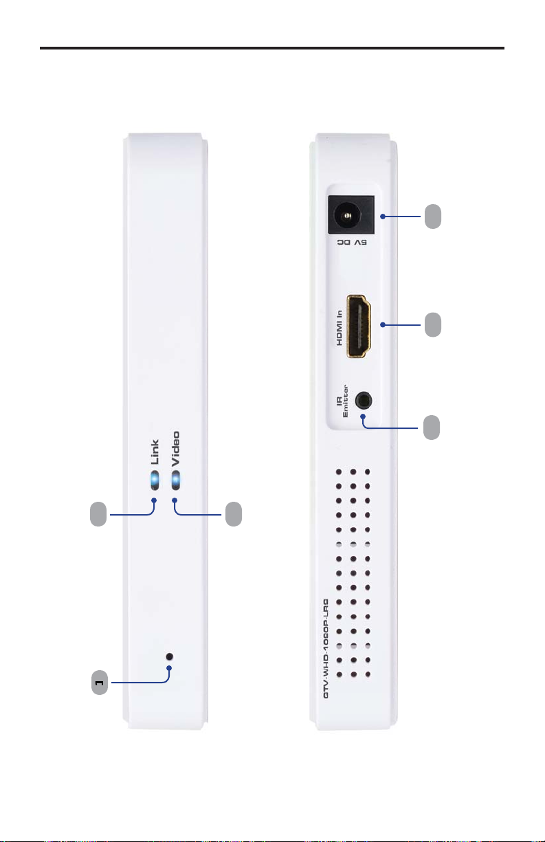
ANEL LAYOU
T
t
t
Sender uni
5
Fron
Back
Page 11
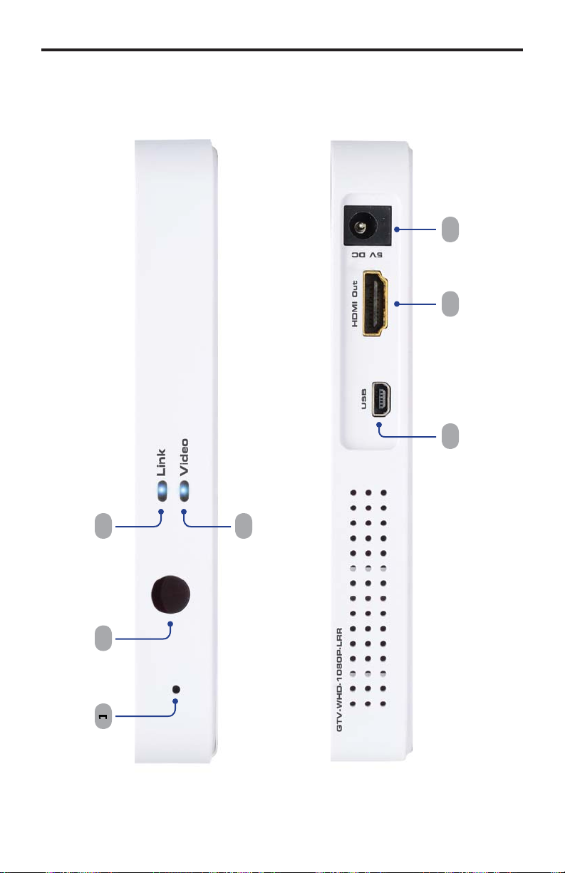
ANEL LAYOU
T
t
t
Receiver uni
7
5
Fron
Back
7
Page 12

t
s
k
o
T
R
source device* to be co
r
t
s
r
source u
k
o
T
t
r
*
ANEL DESCRIPTION
S
Sender Uni
Pairing button
Press and hold this recessed button using a paper clip for approximately 3
econds to pair the Sender unit with the Receiver unit.
Lin
This LED indicator will glow bright blue once a link is established between the
ender unit and the Receiver unit.
Vide
is LED indicator will glow bright blue once a video link is established between
the Sender unit and the Receiver unit.
4 I
onnect the included IR Emitter to this port and place it near the IR sensor of
the
5 HDMI In
This input will accept a single HDMI source device.
6 Powe
onnect the included 5V DC power supply to this receptacle.
Pairing button
Press and hold this recessed button using a paper clip for approximately 3
econds to pair the Sender unit with the Receiver unit.
ntrolled.
Receiver Uni
IR Senso
eceives IR commands from the included IR Remote Control unit and the IR
mote of the
Lin
This LED indicator will glow bright blue once a link is established between the
eceiver unit and the Sender unit.
4 Vide
is LED indicator will glow bright blue once a video link is established between
the Receiver unit and the Sender unit.
5 USB
ini-USB service port (for factory use only).
6 HDMI Ou
onnect the included HDMI cable from this connector to an HD display.
7 Powe
onnect the included 5V DC power supply to this receptacle.
Please see www.gefentv.com for a list of compatible brands and models.
nit to be controlled.
Page 13

IR REMOTE CONTROL UNI
T
u
s
K
n
ess netwo
s
t
t
g
2
4
ayout and Descriptions
7
5
Men
Press this button to display the Setup menu.
Cursor button
sed to control Left, Up, Right, and Down cursor motion within a menu system.
O
Press this button to accept the current operation or menu selectio
4 Delete
When using multiple Sender units, press this button to delete a Sender unit from
the wirel
5 Input Device
When using multiple Sender units, use these buttons to select any of the fi rst
three linked Sender units. Use the Source button to select Senders 4 - 8.
6 Gues
Powers down the wireless system.
7 Add
When using multiple Sender units, press this button to add a Sender unit
source).
Exi
Press this button to cancel an operation or exit any menu system.
9 Source
When usin
different Sender unit.
rk.
multiple Sender units (sources), press this button to select a
Page 14

CONNECTING THE WIRELESS FOR HDMI
cable
d
source device* to be co
eceiver u
g
*
GTV
-WH
D-1
080
P-L
R
r
:
e
does not
s
ces
How to Connect the Wireless for HDMI - Multi-Room Solution
onnect a Hi-Def source to the Sender unit using the included HDMI cable.
onnect an HD display or projector to the Receiver unit using the included
2.
DMI
.
onnect the included 5V DC power supplies to the Sender an
4.
PTIONAL: Connect the included IR emitter to the Sender unit and place it
r the IR sensor of a
To control the IR source connected to the Sender unit, point the source’s IR
mote at the IR sensor on the R
. The Link and Video LED indicators on both the Sender and Receiver unit will
low bright blue to indicate a successful connection between the Sender and
eceiver unit. Ordinarily, no pairing is required out of the box. However, the
ender and Receiver can also be paired manually if needed.
.
NOTE
Th
upport DVI devi
Wireless for HDMI - Multi-Room Solution
.
iver unit and connect them to available electrical outlets.
ntrolled.
nit.
Wiring Diagram for the Wireless for HDMI - Multi-Room Solution
HDMI CABLE
®
®
Receiver
eceive
GTV-WHD-1080P-LR
Please see www.gefentv.com for a list of compatible brands and models.
10
Sender
®
Page 15

1
T
)
ess fo
f
ge
des
t
status of
e
ess fo
OPERATING THE WIRELESS FOR HDMI
he Linking Process
After all the connections have made (see page 10
to the Wirel
r HDMI, the
eceiver unit will attempt to negotiate with the Sender unit.
Status Messa
Provi
Connecting to Sender...
ter a few moments, the source signal will appear on the display. The status
A
information on the curren
th
irel
r HDMI
essage will disappear after a few seconds.
Connected to Sender
1
Page 16

can be used with up to eight Sender units to provide
s
S
network, make
s
U
1:
m
s
Add new Video Source
OPERATING THE WIRELESS FOR HDMI
sing Multiple Sender Units
The
witching capability between Sender units.
Video
Link
Wireless for HDMI R
Figure
iver unit with
ultiple Sender unit
Video
Link
Wireless for HDMI S
Adding a new Video
Video
Link
Wireless for HDMI S
ource
Video
Link
Wireless for HDMI S
Before adding an additional Sender unit to the
ure that a single Sender / Receiver pair function correctly.
1.
onnect the Sender unit to a Hi-Def source using an HDMI cable.
2.
onnect the power supply to the Sender unit.
. Point the IR Remote Control at the Receiver unit and press the
button. The Setup menu will be displayed.
Setup
Remove Video Source
Modify Video Source Name
Disconnect Wireless Link
EN
12
Page 17

C
deo
f
ess
e
f
:
f
ess
e
g
3
g
OPERATING THE WIRELESS FOR HDMI
4.
se the cursor buttons on the IR Remote
ource
rom the Setup menu.
ontrol to select Add new Vi
. Pr
th
OK button. The
Press and hold the Link button on Sender until
Link LED stops blinking
ollowing message will be displayed
. Press and hold down the Pairing button (see pages 6 - 8) on the Sender unit
or about 5 seconds.
Adding Sender
Press OK to continue or Exit to cancel
7. Pr
th
OK button to continue addin
NOTE: When pairin
ename the ones already linked to avoid confusion.
multiple Senders, it is recommended that you
the Sender unit.
1
Page 18

4
network, a progress
:
:
S
ess fo
network.
T
D
OPERATING THE WIRELESS FOR HDMI
As the Sender unit is added to the
bar will be displayed
Adding Sender
After a few moments the source signal connected to the additional Sender
nit will be displayed
. If desired, repeat steps 1 - 7 to add another
Connected to Sender
ender unit to the Wirel
IP:
se the AD
bypass the Setup menu and jump directly to registering the Sender
nit.
button (see page 9) on the IR Remote Control to
1
r
Page 19

s
g
selec
e
:
dif
der
OPERATING THE WIRELESS FOR HDMI
enaming Source
By default, each Sender unit is assigned the name “Sender”. This can be
onfusing when multiple Sender unit are used. However, this identifi er can
be chan
ed to refl ect, for example, the source to which each Sender unit is
nnected.
1. Point the IR Remote Control at the Receiver unit, press the
t
odify Video Source Nam
Setup
Add new Video Source
Remove Video Source
Mo
Disconnect Wireless Link
2.
elect the source to rename from the menu by using the cursor keys
Choose Source to Rename
y Video Source Name
, then press the OK button.
ENU button,
Sender
n
15
Page 20

6
e
e
s
y
s
f
24f
g
j
s
t
xyz
J
T
V
:
OPERATING THE WIRELESS FOR HDMI
. Th
Rename Video Source Nam
elected Source.
se the ▲ and ▼ cursor keys to change the highlighted character.
The ▲ ke
moves forward within the list of available characters and the
key moves backward through the list. The list of available characters
is listed in the table below. The fi rst character (fi rst row, fi rst column) is a
pace and can be used anywhere in the name. The maximum length o
the Source name cannot exceed nine characters, including any spaces.
Figure 2
Available characters for source naming
vw
menu will be displayed, along with the
l
AB
D
F
P
W
Rename Video Source Name
ender
se the ◄ and ► cursor keys to select the character in the name to be
hanged.
1
Page 21

f
butto
e
y
y
OPERATING THE WIRELESS FOR HDMI
4. A
ter the video source has been renamed, press the OK
hanges.
Select Video Source
Sender
BluRa
Setup
n to save th
17
Page 22

8
s
C
e
e
e
source
BluRay
y
BluRay
y
OPERATING THE WIRELESS FOR HDMI
witching between Source
nce two or more Sender units have been connected to a Receiver unit, use the
IR Remote Control unit to switch between each source.
1. Point the IR Remote
2.
tton. Th
se the
Select Video Sourc
Select Video Source
STB
Setup
buttons on the IR Remote Control to select the desired
.
ontrol at the Receiver unit and press the Sourc
menu will be displayed.
Select Video Source
STB
Setup
1
Page 23

g
T
S
OPERATING THE WIRELESS FOR HDMI
.
nce the desired source has been selected, press the OK button.
Select Video Source
TB
BluRay
Setup
4. The screen will
o blank momentarily and the “Connecting to....” status
message will be displayed, indicating that the Receiver unit is switching to
the selected Sender unit (source).
. After a few moments, the selected source signal will be displayed.
Connected to Sender
IP:
se the INPUT DEVICE
emote Control to bypass the Select Video Source menu and
directly switch to another Sender unit.
buttons (see page 9) on the IR
19
Page 24

s
network.
e
2
Add new Video Source
ideo Source
OPERATING THE WIRELESS FOR HDMI
Deleting Source
If a Sender unit (source) will no longer be necessary, it can be removed from the
1. Point the IR Remote Control at the Receiver unit and press the
tton.
Setup
Remove Video Source
Modify Video Source Name
Disconnect Wireless Link
2.
elect Remove Video Sourc
from the Setup menu, using the cursor
buttons on the IR Remote Control.
ENU
Setup
Add new Video Source
Remove V
Modify Video Source Name
Disconnect Wireless Link
0
Page 25

21
butto
e
y
butto
ess
e
butto
BluRay
OPERATING THE WIRELESS FOR HDMI
.
lick the OK
Th
hose Source to Remote menu will be displa
.
elect the source to be removed and press the OK
Choose Source to Remove
STB
DVR
n to confi rm the selection.
ed.
n.
. Pr
th
OK
Removing BluRay
Press OK to continue or Exit to cancel
n to confi rm the removal of the selected device.
7. After a few seconds, the screen will go blank.
Page 26

2
ess
e
E
menu
g
STB
DVR
T
E
OPERATING THE WIRELESS FOR HDMI
. Pr
.
th
SOURC
Select Video Source
DVR
Setup
elect the desired source usin
tton to confi rm the selection.
Select Video Source
button to display the
the cursor buttons. Then, press the OK
elect Video Source
.
STB
Setup
IP:
se the
directly to the Select Video Source menu, when deleting sources.
ELET
button on the IR Remote Control to jump
2
Page 27

23
:
y
OPERATING THE WIRELESS FOR HDMI
11. The “Connecting to...” status message will be displayed
Connecting to DVR...
12. After a few moments, the selected source signal will be displayed.
Connected to DVR
NOTE: The video source will alwa
the source currently being viewed is not deleted.
s need to be selected, even if
Page 28

24
network can be completely disconnected, if necessary.
C
U
butto
g
y
ess fo
network is now in
Disconnect Wireless Link
OPERATING THE WIRELESS FOR HDMI
Disconnecting the Wireless Link
The
This can be used in order to restrict the source from being viewed.
1. Point the IR Remote
ontrol at the Receiver unit and press the
EN
tton.
2.
elect
isconnect Wireless Link and press the OK
Setup
Add new Video Source
Remove Video Source
Modify Video Source Name
n.
. After a few seconds, the screen will go blank. A status message, indicatin
that the wireless has been turned off, will be displa
ed. The Wirel
tandby mode
r
Wireless Off
Page 29

2
ess
e
e
:
OPERATING THE WIRELESS FOR HDMI
econnecting the Wireless Link
Pr
th
Sourc
message will be displayed
Connecting to DVR...
2. After a few seconds, the wireless link will be restored and the source signal
will be displayed.
button on the IR Remote Control. The “Connecting to...”
Connected to DVR
5
Page 30

26
e
The
can be powered-down when not in use.
has been
OPERATING THE WIRELESS FOR HDMI
ower-Down Mod
1. Point the IR Remote Control at the Receiver unit and press the
tton.
2. After a few seconds, the screen Receiver and Sender unit(s) will powerdown. A status message, indicating that the
owered-down, will be displayed.
UEST
Powering Down...
Page 31

. After the
has been successfully powered-down, the
Off
2
Wireless
Wireless Off
OPERATING THE WIRELESS FOR HDMI
” message will be displayed on the screen.
owering-Up after a Power-Down
1. Point the IR Remote Control at the Receiver unit and press the
tton.
2. The “Connecting to...” message will be displayed.
. After a few moments, the selected source signal will be restored.
Connected to DVR
7
UEST
Page 32

p
e
e
y)
C
)
”
(
)
g)
e
SPECIFICATION
S
28
perating Frequency.................................................................................... 5 GHz
upported resolutions...................................................................... 480p to 1080
Video Input Connector (Sender).......................... (1) HDMI Type A, 19-pin, femal
Video Output Connector (Receiver)..................... (1) HDMI Type A, 19-pin, femal
B Connector (Receiver)......................................... (1) Mini-B (factory use onl
Power Supply (Sender/Receiver)............................................................ (2) 5V D
Power Consumption (Sender / Receiver)........................... 8W (max.) / 8W (max.
Dimensions (Sender / Receiver) (W x H x D)............................. 5.83” x 0.8” x 3.8
hipping Weight........................................................................... 2.8 lbs (1.27 k
148mm x 20mm x 96mm
All features and specifi cations are subject to change without notic
Page 33

WARRANTY
f
y
s
N
.
2
efen warrants the equipment it manufactures to be free from defects in material
and workmanship.
I
equipment fails because of such defects and Gefen is notifi ed within two (2)
ears from the date of shipment, Gefen will, at its option, repair or replace the
quipment, provided that the equipment has not been subjected to mechanical,
lectrical, or other abuse or modifi cations. Equipment that fails under conditions
other than those covered will be repaired at the current price of parts and labor in
ect at the time of repair. Such repairs are warranted for ninety (90) days from
the day of reshipment to the Buyer.
This warranty is in lieu of all other warranties expressed or implied, including
without limitation, any implied warranty or merchantability or fi tness for any
articular purpose, all of which are expressly disclaimed.
1. Proof of sale may be required in order to claim warranty.
2.
ustomers outside the US are responsible for shipping charges to and from
efen.
.
opper cables are limited to a 30 day warranty and cables must be in their
original condition.
The information in this manual has been carefully checked and is believed to
be accurate. However, Gefen assumes no responsibility for any inaccuracies
that may be contained in this manual. In no event will Gefen be liable for
direct, indirect, special, incidental, or consequential damages resulting from
any defect or omission in this manual, even if advised of the possibility of such
damages. The technical information contained herein regarding the features and
pecifi cations is subject to change without notice.
For the latest warranty coverage information, refer to the Warranty and Return
Policy under the Support section of the Gefen Web site at www.gefen.com.
RODUCT REGISTRATIO
lease register your product online by visiting the Register Product page
nder the Support section of the Gefen Web site
9
Page 34

Page 35

Page 36

Page 37

Rev A
3
1
800
6900
20
w
m
1-
-545-
ww.gefentv.com support@gefentv.co
Pb
This product uses UL or CE listed power supplies.
Nordhoff St., Chatsworth CA 9131
818-772-9100 fax: 818-772-91
 Loading...