

Page 1

Ethernet Over Coax
CO
TV-ETH-2-
ser Manual
www.gefentv.com
AX
Page 2

ASKING FOR ASSISTANC
E
t
0
0
0
:
ST
:
C
e
0600
1
e
C
©
A4
echnical Suppor
Telephone (818) 772-910
(800) 545-690
Fax (818) 772-912
echnical Support Hours
:00 AM to 5:00 PM Monday thru Friday P
Write To
efen, LL
o Customer Servic
2
Nordhoff St
hatsworth, CA 9131
www.gefentv.com
upport@gefentv.com
Notic
efen, LLC reserves the right to make changes in the hard ware, packaging and
any accompanying doc u men ta tion without prior written notice.
GefenTV Ethernet Over Coax is a trademark of Gefen, LL
2011 Gefen, LLC. All rights reserved.
All trademarks are the property of their respective owners.
ev
Page 3

CONTENT
S
oduction
t
t
n
x
e
n
n
e
y
1 Intr
2 Operation Notes
Features
4 Sender Panel Layou
Sender Panel Descriptions
Receiver Panel Layou
7 Receiver Panel Descriptions
Ethernet over Coax software installatio
11 Connecting the Ethernet Over Coa
17 Automatic Security Setup Featur
19 Advanced Confi guratio
24 Web Confi guratio
27 Firmware Update Procedur
28 Specifi cations
29 Warrant
Page 4

x
cables
INTRODUCTIO
N
ongratulations on your purchase of the GefenTV Ethernet Over Coax. Y our
omplete satisfaction is very important to us.
efen TV
efen TV is a unique product line catering to the growing needs for innovative
ome theater solutions. We specialize in total integration for your home theater,
while also focusing on going above and beyond customer expectations to ensure
ou get the most from your hardware. We invite you to explore our distinct
roduct line and hope you fi nd your solutions. Don’t see what you are looking for
ere? Please call us so we can better assist you with your particular needs.
he Gefen Ethernet Over Coa
The Gefen TV Ethernet Over Coaxial Sender and Receiver units send RJ-45
Ethernet over RG-59 or RG-6 Coax cable at a distance of up to 300m/1000 feet.
Ideal for legacy installations where Coaxial cable is already permanently in place,
these devices breathe new life into remote network extensions where re-wiring is
ot possible.
How It Works
onnect your existing Ethernet network cables to the Ethernet Over Coaxial
ender unit, then plug in your Coaxial cable to the Coaxial jack on the Sender
nit. At the other end of your Coaxial cable run, attach the Ethernet Over Coax
eceiver unit and your network cables. Power-cycle your equipment. You will
ow receive Ethernet network signals at the end of your cable run as if you had
led the run with Ethernet
.
Page 5

/
/
OPERATION NOTE
S
READ THESE NOTES BEFORE INSTALLING OR
OPERATING THE GEFENTV ETHERNET OVER COAX
• This device passes all 10
IP, NETBUEI, Microsoft Networking, etc.) at speeds of up to 200Mbps (Full
duplex fast Ethernet).
• All devices connected to the sending and receiving nodes must be on the
ame subnet with unique IP addresses to communicate properly.
•
ultiple receiving nodes can be used on the same coaxial cable system to
xtend the network to multiple locations.
100BASE-T Ethernet network protocols (TCP
Page 6

e
)
e
QOS
t
n
t
t
e
FEATURE
S
Features
•
upports up to 200 Mbps data transmission rat
• Extension of up to 1000 feet (300 meters
• Web confi guration for easy maintenanc
• Features include IGMP multicast, VLAN, and
• 3DES 168 bits encryption used for secure operatio
• Four RJ-45 Ethernet ports
ackage Includes
1) Ethernet Over Coax - Sender Uni
1) Ethernet Over Coax - Receiver Uni
2) 3 ft. Ethernet Patch Cabl
2) Power Adapter Cables
packet managemen
Page 7
p
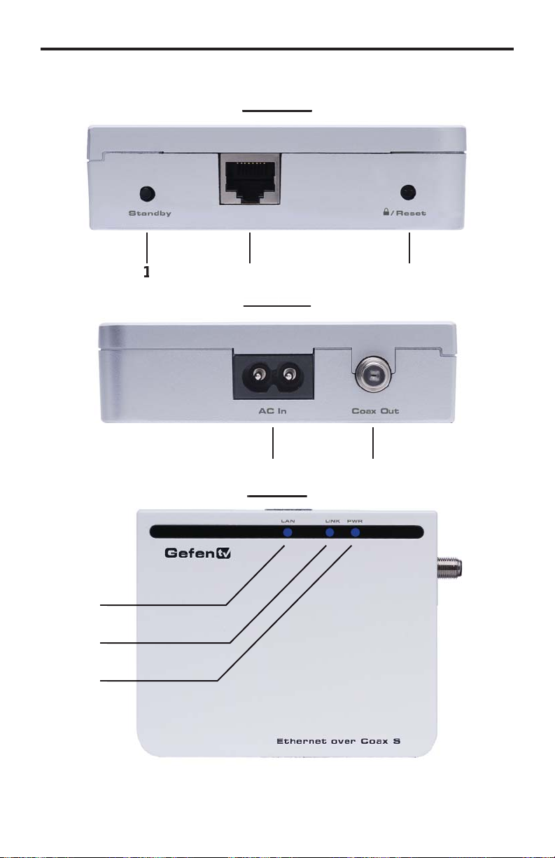
SENDER PANEL LAYOU
T
Front Panel
ack Pan
5
7
Page 8

SENDER PANEL DESCRIPTION
S
f
t
t
t
D
source is
D
g
.
D
1. Standby Button
Pressing this will put the sending unit in standby mode. The unit will not
trans
er any information to the receiving unit in this mode. To release
tandby mode, simply press the button again.
.
thernet Input Por
onnects to the Ethernet source (i.e a router, computer, or Internet
onnection) via a standard network cable.
. Security/Reset Button
Pressing this button for 2 seconds will activate the Automatic Security
onfi guration (please see page 17). Pressing this button for more than 10
econds will perform a factory reset.
. AC Power Cable Inpu
Input for the supplied AC power cable.
5. Coaxial Outpu
oaxial output to link the sending and receiving units together. This
onnector will support RG-6 and RG-59 cables.
6.
AN LE
This LED will activate when a connection to a valid Ethernet
stablished. It will blink when activity is detected to signify that data is
actively being traffi cked to and from the receiver.
7.
ink LE
This LED will activate once a link has been established between the sendin
and receiving units. It will blink when activity is detected to signify that data is
actively being traffi cked
.
ower LE
This LED will activate once the included power supply is properly connected.
5
Page 9
p
1
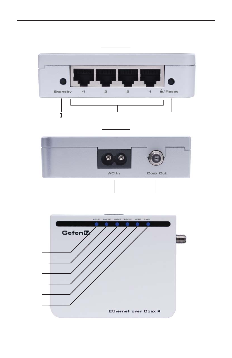
RECEIVER PANEL LAYOU
T
Front Panel
Back Panel
5
7
10
1
Page 10

RECEIVER PANEL DESCRIPTION
S
f
)
t
t
D
o
D
o
D
o
D
o
D
g
D
1. Standby Button
Pressing this will put the receiving unit in standby mode. The unit will not
trans
er any information to the sending unit in this mode. To release standby
ode, simply press the button again.
.
thernet Input Port ( 1 through 4
onnects to an Ethernet device (i.e a computer or gaming system) via a
tandard network cable. 4 ports are available for 4 separate devices.
. Security/Reset Button
Pressing this button for 2 seconds will activate the Automatic Security
onfi guration (please see page 17). Pressing this button for more than 10
econds will perform a factory reset.
. AC Power Cable Inpu
Input for the supplied AC power cable.
5. Coaxial Outpu
oaxial output to link the sending and receiving units together. This
onnector will support RG-6 and RG-59 cables.
6.
AN 1 LE
This LED will activate when a connection from a valid Ethernet device t
Ethernet port 1 is established. It will blink when activity is detected to signify
that data is actively being traffi cked to and from this port.
7.
AN 2 LE
This LED will activate when a connection from a valid Ethernet device t
Ethernet port 2 is established. It will blink when activity is detected to signify
that data is actively being traffi cked to and from this port.
.
AN 3 LE
This LED will activate when a connection from a valid Ethernet device t
Ethernet port 3 is established. It will blink when activity is detected to signify
that data is actively being traffi cked to and from this port.
.
AN 4 LE
This LED will activate when a connection from a valid Ethernet device t
Ethernet port 4 is established. It will blink when activity is detected to signify
that data is actively being traffi cked to and from this port.
10.
ink LE
This LED will activate once a link has been established between the sendin
and receiving units. It will blink when activity is detected to signify that data is
actively being traffi cked to and from the sender.
11.
ower LE
This LED will activate once the included power supply is properly connected.
7
Page 11

x
g
THERNET OVER COAX SOFTWARE INSTALLATIO
N
How to Connect the GefenTV Ethernet Over Coa
1. Download the latest software from the Support section on the Gefen Web
ite.
2. Extract the contents of the .zip fi le to a folder on your Desktop. The default
older name is: Gefen_CD_vX (where X is the version number of the
oftware).
.
nder the Gefen_CD_vX directory, there will be two subdirectories: /Coax
and /PL.
4. Double-click on the autorun.exe fi le located under the /Coax subdirectory.
.
lick on the Install Utility option.
.
hoose your preferred language from the drop-down list on the Installer
Language dialog box (currently English is the only selectable language).
Page 12

THERNET OVER COAX SOFTWARE INSTALLATIO
N
.
ake sure all other applications are closed, then press the Next button to
ntinue.
. Please read the license agreement and click on the I Agree button to
ntinue.
Page 13

“C:\
g
y
THERNET OVER COAX SOFTWARE INSTALLATIO
N
7. Please choose the program installation destination. The default location
is
Program Files\Gefen TV Ethernet Over Coax”. To set your own
destination, click on the browse button and navi
ocation. Click the install button to continue.
ate to your preferred
. The program fi les will copy to the specifi ed location in the previous step.
When the process is complete,
nish button to complete the software installation process.
ou will see the window below. Click on the
10
Page 14

1
G-6)
)
.
g
g
CONNECTING THE ETHERNET OVER COAX
1.
onnect the source (i.e. computer, router, switch) to the GefenTV Ethernet
ver Coax sender unit using the supplied CAT-5e cable.
onnect the GefenTV Ethernet Over Coax sender unit to a coaxial (RG-59
or R
plitter.
.
4.
to the GefenTV Ethernet Over Coax receiver unit. Up to four devices are
upported.
.
ending and receiving units.
OWER LED:nce the power cable is connected, the Power LED should
me active with a solid blue color
AN LED: When a valid Ethernet connection is detected on the sending and
eceiving Ethernet jacks, their corresponding LED’s will become active and
hould emit a solid blue color.
INK LED: The Link LED should be fl ashing red on initial boot up. Once a link
between the sending and receiving units has been established, it will emit a solid
lue color on both units.
cable system. Please ensure that the connected coaxial cable
stem has an available endpoint, either directly or through a coaxial cable
onnect the GefenTV Ethernet Over Coax receiver unit to the coaxial cable
stem.
onnect the Ethernet devices (i.e. computer, game system, set-top box
onnect the included power cables to both the GefenTV Ethernet Over Coax
IMPORTANT: The Link LED must be emitting a sold blue color before
onfi guration can continue. If this LED continues to fl ash red on both the sendin
and receiving units, it is possible that they are not physically connected within the
urrent coaxial cable system. Please confi rm that both the sending and receivin
nits are attached to the same coaxial cable system.
1
Page 15

CONFIGURING THE ETHERNET OVER COA
X
f
oca
ode
ocatio
nce both the sending and receiving units are linked and powered, basic
onfi guration can proceed. This section of the manual refers to the sending unit
as the LOCAL NODE, and the receiving unit as the REMOTE NODE.
NOTE: The
basic secure network. These steps are optional, as the nodes will function with
their default settings. However, for security and performance purposes, it is
ecommended that the following steps be performed. Automatic confi guration is
also possible using the Automatic Security Confi guration feature on page 17 in
ieu of the procedure outlined in this section.
1. Ensure that both the local and remote nodes are powered and are properly
inked.
2.
.
Start Menu \ All Programs \ GefenTV Ethernet Over Coax \ Gefen TV Confi g Tool
4. The introduction screen should appear as the image below. Click on the next
ollowing steps are for manual confi guration of the nodes for a
onfi rm that the computer with the installed GefenTV Ethernet Over Coax
tware is connected to the l
tart the
tton to continue.
efen TV Confi g Tool from this l
l n
.
n:
. The program will begin to search for all connected nodes.
12
Page 16

3
CONFIGURING THE ETHERNET OVER COA
X
ese nodes as
ocal and remote nodes must use
.
nce all possible nodes have been detected, the program will display all of
th
The local node that the computer is connected to will appear as the “ETH
onnected node”. All remote nodes will be listed as “PLC connected nodes”.
in the window below.
NOTE: Both the l
ncryption passwords for proper operation. These will be confi gured in the next
tep. However, it is important to confi gure the remote nodes fi rst. If the local node
is confi gured fi rst, all remote nodes will become inaccessible and will have to be
emoved from their locations and physically connected to the computer, where
they can be confi gured to match the local node’s settings.
To begin confi guration, click on the mac address of the remote node (PLC
onnected node) and then click on the next button.
the same Net ID and
1
Page 17

4
CONFIGURING THE ETHERNET OVER COA
X
:
D
oca
S
)
D
.
The PLC node confi guration screen is separated into the following items
NET I
This is the name of the network. This name must be the same for both the l
and remote nodes for proper operation. The NET ID can be an ASCII string up to
20 characters long.
l
NCRYPTION KEY
This is the password needed for network authentication by all nodes. If you wish
to set an encryption key, please set the NET ID fi rst. The password can be an
ASCII string up to 24 characters long.
ALIA
This name is for easy identifi cation of the node. This can be an ASCII string of up
to 10 characters long. This fi eld is optional.
NEW PASSWORD (CONFIGURATION PASSWORD
This is to set the confi guration password. If a new password is set here, the
onfi guration tool will ask for it every time you access the node. The default
assword is “paterna”. This fi eld is optional.
CONFIRM PASSWOR
The password entered into the new password listing above must also be entered
ere. This is for confi rmation purposes.
Enter the Net ID, encryption key, and alias into the corresponding fi elds. Once
these fi elds are completed, click on the next button to continue.
1
Page 18

CONFIGURING THE ETHERNET OVER COA
X
.
nce the update is complete, a message will appear to indicate the update
was successful. Click on the ok button to continue.
10.
nce the update to the remote node is complete, you will be presented with
a window that will give the option to either return to the main confi guration
window or continue with advanced confi guration.
For basic usage, it will not be necessary to continue to the advanced
onfi guration. For advanced options, please see the ADVANCED
CONFIGURATION
lick on the next button.
ection on page 19. To continue with the basic confi guration,
15
Page 19

6
CONFIGURING THE ETHERNET OVER COA
X
11.
nce the confi guration for the remote node is complete, the local node will
then have to be confi gured. Click on the local node which is labeled as the
ETH connected node” and press next to continue.
12.
sing the same Net ID and encryption key from the remote node, input
the same information into the corresponding fi elds for the local node. The
Alias fi eld should be set to a different name as the remote node for easy
identifi cation.
nce the information has been input, click on the next button to continue. A
onfi rmation window will appear once the update is complete. The same window
in step 10 will appear with the option to continue with the advanced confi guration.
It is not necessary to continue with the advanced confi guration for basic
operation. Click on the next button to return to the main confi guration window and
xit the confi guration tool by clicking on the exit button.
1
Page 20

A
UTOMATIC SECURITY CONFIGURATION FEATUR
E
f
.
y
To quickly setup the Gefen TV Ethernet Over Coaxial for secure use, the
Automatic Security Confi guration Mode (ASCM) can be activated on each node.
Follow the below steps to automatically setup a secure connection between
ultiple nodes.
It is important to understand these concepts be
Automatic Security Confi guration
•
aster Node (Fixed Access Point) - The Master node is the unit that all of
the Slave nodes use to copy the Net ID and Encryption Key from. Because
all of the nodes on a network need to have the same Net ID and encryption
ey to operate properly together, there needs to be a single Master node
that stores the information that all other Slave nodes will use to properl
onfi gure themselves. A Master node is indicated by its Power LED glowing
a solid RED color. It is recommended to have only one Master node on the
xial network.
•
lave Node (Normal) - A node in this mode will be indicated by its Power
LED glowing a solid Blue color. Multiple Slave nodes can be on the same
xial network.
• Automatic Security Confi guration Mode (ASCM) - This mode is initialized
by pressing and holding the Security/Reset button on the front panel for
approximately 2 seconds. Once the node’s Power LED begins fl ashing RED,
elease the button. This mode lasts for approximately 30 seconds and will
eturn to normal operation after this time period.
• Both the Master and Slave nodes must be in ASCM for the automatic
rocedure to complete successfully.
• When a Slave node initializes ASCM, it will fi rst attempt to fi nd a Master
ode in ASCM. If a Master node in ASCM is not found, it will assume the role
of the Master node. To avoid accidentally setting a Slave node as a Master
ode, make sure that the Master node is in ASCM when activating a Slave’s
ASCM.
ore proceeding with the
• Any Slave node that assumes the role of a Master node will automatically
ave a random ASCII Net ID and Encryption Key generated.
•
onnect the computer with the installed Gefen TV Confi g Tool software to
the node that you wish to initially set as the Master node.
• If a node is connected to media server or router, it is recommended that this
ode be set as the Master node for increased performance.
Please refer to the next page for step by step instructions on how to activate the
Automatic Security Confi guration feature for the Gefen TV Ethernet Over Coax
.
17
Page 21

8
AUTOMATIC SECURITY CONFIGURATIO
N
ode
f
odes have
y
1.
onnect the computer with the installed Gefen TV software to the node you
wish to set as the Master n
2. Press and hold the Security/Reset button on the node (ASCM), located on
ront panel, for approximately 2 seconds. The Power LED should begin
the
to fl ash RED, then release the button.
.After approximately 30 seconds, the Power LED should stop fl ashing and
low solid RED. This indicates that it is now a Master node. If this node was
a Slave node (normal node) before this process, it will now have a randomly
enerated ASCII Net ID and Encryption Key set.
4.
pen the Gefen TV Confi g Tool (page 12). There should be a random
ASCII value as the Net ID. If you wish to use this Net ID for the other Slave
odes, proceed to step 5. Otherwise, you can now set your own Net ID and
ncryption password which will be applied to all of the Slave nodes in the
ext step. To do this, click on the local “ETH connected node” MAC address
and press the next button. Change only the Net ID and encryption password
elds and click on the next button. Once the local node has been updated,
roceed to step 5.
. For this step to complete successfully, both the Master and Slave nodes
ave to be in ASCM. To do this, press and hold the Security/Reset button on
the Master node for approximately 2 seconds. The Power LED should begin
ashing RED. Within 30 seconds, press and hold the Security/Reset button
on the Slave node(s) for 2 seconds to enter ASCM. The Slave node’s Power
LED should also begin to fl ash while it receives the Net ID and Encryption
Key information from the Master node. Once the Power LED on both the
aster and Slave nodes stop fl ashing and glow solid, the setup will be
omplete. Check this by opening the Gefen TV Confi g Tool and seeing that
ll n
the same Net ID.
.
NOTE: If the Slave nodes are located at a great distance from the Master node,
it is recommended that Step 5 be repeated for each Slave node separately.
The window that each device remains in ASCM is only 30 seconds, and it may
ot be possible to put all Slave nodes in the ASCM within the time frame. It is
also possible to temporarily relocate the Slave nodes to a coaxial port closer
to the Master node for this confi guration process, and then move them to their
ermanent location after this process is complete. If a Slave node is accidentall
et as a Master node, you can hard reset the node by pressing and holding the
ecurity/Reset button for approximately 10 seconds. This will revert the node to a
lave node and reset all internal confi gurations to factory settings.
1
Page 22

ADVANCED CONFIGURATIO
N
t
t
There are optional advanced settings that can be confi gured for each node. The
advanced menu can be accessed directly through the main confi guration page.
lick on the MAC address of the node you wish to confi gure and click on the
advanced button to the left of the node listing.
ENERAL
Hardware Rese
This will reboot the node. Settings made in this menu will be applied once the
is restarted.
Factory Rese
This will return the node to factory default settings. A password is required to
omplete this operation. The default password is “betera”. This has the same
ect as pressing and holding the Securty/Reset button on the front panel for
approximately 10 seconds.
19
Page 23

ADVANCED CONFIGURATIO
N
e
e
:
Firmware Updat
This section is used to update the node’s fi rmware from a server location. Please
ee the Firmware Update section on page 27 for full details.
pgrade Firmwar
This section is used to update the node’s fi rmware from a fi le. Please see the
Firmware Update section on page 27 for full details.
NETWORK
IP Confi guration
For access to the node’s web confi guration tool an IP address must be assigned.
ptions are
Fixed - Manually assigned IP address
DHCP - IP assigned by the networks DHCP server
Fixed IP Confi guration
Assign an IP address, subnet mask, and default gateway for web tool access.
lick on the Update button to apply settings made in this tab.
0
Page 24

ADVANCED CONFIGURATIO
N
T
t
ULTICAS
IGMP Multicas
This option will enable or disable the node’s ability to transmit IGMP multicast
ta.
SECURITY
The security tab will allow the user to adjust the confi guration password, the
ncryption password, the network ID, and the alias for the node. For a detailed
description of each of these options, please see page 14.
Page 25

ADVANCED CONFIGURATIO
N
g
S
:
y
y
p
)
)
y
LA
This option will enable or disable the node’s ability to accept VLAN data. If this
eature is enabled on one of the nodes, it must be set on all other for VLAN ta
ackets to pass.
O
(quality of service) is supported for managing traffi c between nodes. The
upported protocols are
1. TCP port priorit
2.
.
. DSCP (RFC 2475
. No Priorit
DP port priorit
02.1
TOS (RFC 1122
2
Page 26

ADVANCED CONFIGURATIO
N
S
Q
:
y
y
y
y
y
y
n
n
ADAVANCED QO
(quality of service) prioritization. Rule 1 will be applied to all packets fi rst
and then Rule 2. Prioritization protocols are
1.
DP is high priority, TCP is low priorit
2. TCP is high priority, UDP is low priorit
.
DP port XXXX is high priority, the rest is low priorit
4.
DP port XXXX is low priority, the rest is high priorit
. TCP port XXXX is high priority, the rest is low priorit
. TCP port XXXX is low priority, the rest is high priorit
7.
se 802.1p prioritizatio
. No prioritizatio
Page 27

WEB CONFIGURATIO
N
address has been se
WEB UTILITY
access
open
g
A
N
A
t
If an IP
to the
our web browser and type the ip address into the address fi eld. The IP address
is dependant on the IP Confi guration Setting assigned on page 20. The IP
address can either be assi
anually assigned.
UTHENTICATIO
The browser should open the authentication page displayed below.
t in the ADVANCE CONFIGURATION PANEL
will be enabled. To
ned by the DHCP server or a static IP address can be
the
WEB UTILITY,
uthentication
To enter the WEB UTILITY, enter the confi guration password. The default
assword is “paterna” unless modifi ed during the setup stage on page 14.
Factory Rese
The unit can be reset to factory settings from this menu. Enter the factory reset
assword. The default password is “betera”.
Page 28

WEB CONFIGURATIO
N
E
N
A
AIN PAG
The main page will display general confi guration information. Clicking on
the further information link will navigate to a new page with all the current
onfi guration information (see page 26). Clicking on the change confi guration link
will navigate to a new page where all confi guration options will be available for
adjustment (see below).
WEB CONFIGURATIO
This page will allow the user to adjust all options that are available just as in the
DVANCED CONFIGURATION PANEL in theEFENTV CONFIG TOOL
5
Page 29

WEB CONFIGURATIO
N
:
n
n
n
n
(QOS)
n
eset
e
ease refe
pg
N
:
n
pg
g g
The confi guration options are as follows
AC Confi guratio
Network Confi guratio
ulticast Confi guratio
VLAN Confi guratio
Priority Confi guration
ecurity Confi guratio
rdware R
Flash Upgrad
Pl
or information on the above categories. Going back to the main page can be
done by clicking on any of the
FURTHER INFORMATIO
This page will display all of the information and status of the current node. The
ollowing sections are listed
r to theADVANCED CONFIGURATION section, starting on page 19,
links.
stem Informatio
AC Status
Network Status
PHY Status
ulticast Status
VLAN Status
Priority Status
ecurity Status
Information on this page is not confi gurable. If you wish to make adjustments,
eturn to the main menu by clicking on any of the
the page. Then click on the
age).
(also available on the main
links on
Page 30

FIRMWARE UPDATE PROCEDUR
E
P
address
d
y)
)
n
e
e
n
The fi rmware for the GefenTV Ethernet Over Coax can be updated by FTP,
TFTP, or a direct fi le. The fi rmware update can be executed from either the
ADVANCED CONFIGURATION PANEL, or the WEB UTILITY
PDATE VIA THE ADVANCED CONFIGURATION PANEL
Firmware updates can be accomplished from the General tab in the ADVANCED
CONFIGURATION PANEL
ADVANCED CONFIGURATION PANEL
pgrade Via FTP or TFT
See page 19 for instructions on how to enter the
1.
elect the update protocol. Either FTP or TFTP
2. Enter the server IP
. Enter the user name and passwor
4. Enter the name of the fi le (if the fi le is not in the root directory of the TFTP or
FTP directory, you have to write the whole route from root server director
.
elect which section you would like to update (Firmware, Loader or Factory
ettings
.
lick on the fi rmware update butto
pgrade Via Fil
1.
se the browse button to the right of the fi rmware fi le window and select the
rmware update fi le. You can also manually type the full path to the fi rmware
l
2.
lick on the upgrade fi rmware butto
NOTE: This procedure is the same using the web utility. The web update section
is located in the change confi guration settings, which is accessible from the main
.
7
Page 31

C
n
x
)
g
)
g
t
SPECIFICATION
S
tandard Support ........................................................ UPA DHS (200 Mbps) PL
Interface ....... One Power Line port / One coaxial port / 4 Ethernet 10/100M Ports
ecurity .......................................................................... 3DES 168 bits encryptio
Power ................................................................. AC 100~240V / 50~60Hz / 0.15A
Power Consumption ............................................. 8W/230V Max & 7W/110V Ma
perating Temp ....................................................................... 0~40ºC (32~104ºF
perating Humidity ..................................................... 10%~90% non-condensin
torage Temp Range ............................................................ -20~70ºC (-4~158ºF
torage Humidity .......................................................... 5%~95% non-condensin
torage Altitude ................................................................ Sea level to 40,000 fee
ertifi cations ........................................ FCC Part 15, Part B, Class B, CE Class B
Page 32

WARRANTY
f
N
.
efen warrants the equipment it manufactures to be free from defects in material
and workmanship.
I
equipment fails because of such defects and Gefen is notifi ed within two (2)
ears from the date of shipment, Gefen will, at its option, repair or replace the
quipment, provided that the equipment has not been subjected to mechanical,
lectrical, or other abuse or modifi cations. Equipment that fails under conditions
other than those covered will be repaired at the current price of parts and labor in
ect at the time of repair. Such repairs are warranted for ninety (90) days from
the day of reshipment to the Buyer.
This warranty is in lieu of all other warranties expressed or implied, including
without limitation, any implied warranty or merchantability or fi tness for any
articular purpose, all of which are expressly disclaimed.
1. Proof of sale may be required in order to claim warranty.
2.
ustomers outside the US are responsible for shipping charges to and from
efen.
.
opper cables are limited to a 30 day warranty and cables must be in their
original condition.
The information in this manual has been carefully checked and is believed to
be accurate. However, Gefen assumes no responsibility for any inaccuracies
that may be contained in this manual. In no event will Gefen be liable for
direct, indirect, special, incidental, or consequential damages resulting from
any defect or omission in this manual, even if advised of the possibility of such
damages. The technical information contained herein regarding the features and
pecifi cations is subject to change without notice.
For the latest warranty coverage information, refer to the Warranty and Return
Policy under the Support section of the Gefen Web site at www.gefen.com.
RODUCT REGISTRATIO
lease register your product online by visiting the Register Product page
nder the Support section of the Gefen Web site
9
Page 33

ev
A4
1
0
m
Nordhoff St., Chatsworth CA 9131
1-800-545-6900 818-772-9100 fax: 818-772-912
www.gefentv.com support@gefentv.co
Pb
This product uses UL listed power supplies.
 Loading...