

Page 1
3GSDI
x
4 1
SOURCES
DISPLAYS
HD Switcher
Audio
Embedder
w/ Audio Decoding
GTV-AUDDEC-N
User Manual
Rev A4
Page 2

4x1 HD Switcher w/ Audio Decoding
Important Safety Instructions
GENERAL SAFETY INFORMATION
1. Read these instructions.
2. Keep these instructions.
3. Heed all warnings.
4. Follow all instructions.
5. Do not use this product near water.
6. Clean only with a dry cloth.
7. Do not block any ventilation openings. Install in accordance with the manufacturer’s
instructions.
8. Do not install or place this product near any heat sources such as radiators, heat
registers, stoves, or other apparatus (including ampliers) that produce heat.
9. Do not defeat the safety purpose of the polarized or grounding-type plug. A polarized
plug has two blades with one wider than the other. A grounding type plug has two
blades and a third grounding prong. The wide blade or the third prong are provided for
your safety. If the provided plug does not t into your outlet, consult an electrician for
replacement of the obsolete outlet.
10. Protect the power cord from being walked on or pinched particularly at plugs,
convenience receptacles, and the point where they exit from the apparatus.
11. Only use attachments/accessories specied by the manufacturer.
12. To reduce the risk of electric shock and/or damage to this product, never handle or
touch this unit or power cord if your hands are wet or damp. Do not expose this
product to rain or moisture.
13. Unplug this apparatus during lightning storms or when unused for long periods of time.
14. Refer all servicing to qualied service personnel. Servicing is required when the
apparatus has been damaged in any way, such as power-supply cord or plug is
damaged, liquid has been spilled or objects have fallen into the apparatus,
the apparatus has been exposed to rain or moisture, does not operate normally,
or has been dropped.
15. Batteries that may be included with this product and/or accessories should never be
exposed to open ame or excessive heat. Always dispose of used batteries
according to the instructions.
ii
Page 3

4x1 HD Switcher w/ Audio Decoding
Warranty Information
Gefen warrants the equipment it manufactures to be free from defects in material and
workmanship.
If equipment fails because of such defects and Gefen is notied within two (2) years from
the date of shipment, Gefen will, at its option, repair or replace the equipment, provided
that the equipment has not been subjected to mechanical, electrical, or other abuse or
modications. Equipment that fails under conditions other than those covered will be
repaired at the current price of parts and labor in effect at the time of repair. Such repairs
are warranted for ninety (90) days from the day of reshipment to the Buyer.
This warranty is in lieu of all other warranties expressed or implied, including without
limitation, any implied warranty or merchantability or tness for any particular purpose, all of
which are expressly disclaimed.
1. Proof of sale may be required in order to claim warranty.
2. Customers outside the US are responsible for shipping charges to and from Gefen.
3. Copper cables are limited to a 30 day warranty and cables must be in their original
condition.
The information in this manual has been carefully checked and is believed to be accurate.
However, Gefen assumes no responsibility for any inaccuracies that may be contained
in this manual. In no event will Gefen be liable for direct, indirect, special, incidental, or
consequential damages resulting from any defect or omission in this manual, even if
advised of the possibility of such damages. The technical information contained herein
regarding the features and specications is subject to change without notice.
For the latest warranty coverage information, refer to the Warranty and Return Policy under
the Support section of the Gefen Web site at www.gefen.com.
PRODUCT REGISTRATION
Please register your product online by visiting the Register Product page under the
Support section of the Gefen Web site.
iii
Page 4

4x1 HD Switcher w/ Audio Decoding
Contacting Gefen Technical Support
Gefen, LLC
c/o Customer Service
20600 Nordhoff St.
Chatsworth, CA 91311
Telephone: (818) 772-9100
(800) 545-6900
Fax: (818) 772-9120
Email: support@gefentv.com
Visit us on the Web: www.gefentv.com
Technical Support Hours: 8:00 AM to 5:00 PM Monday - Friday, Pacic Time
4x1 HD Switcher w/ Audio Decoding is a trademark of Gefen, LLC.
Gefen, LLC reserves the right to make changes in the hardware, packaging, and any
accompanying documentation without prior written notice.
HDMI, the HDMI logo, and High-Denition Multimedia Interface are trademarks or
registered trademarks of HDMI Licensing in the United States and other countries.
Manufactured under license from Dolby Laboratories.
Dolby, Pro Logic, and the double-D symbol
are registered trademarks of Dolby Laboratories.
© 2011 Gefen, LLC. All Rights Reserved.
All trademarks are the property of their respective owners.
Important Notice
iv
iv
Page 5

3GSDI Audio Embedder
4x1 HD Switcher w/ Audio Decoding
Operating Notes
• The Digital Audio Decoder for HDMI has 8 RCA outputs, intended to be used with a
separate amplier, and supports a maximum of six discrete channels of audio.
2 additional connectors are available for bi-amping the front left and right channels.
• This product was intended for use with a separate audio amplier. The RCA output
connectors on the rear panel will require the use of an audio amplier to produce
adequate volume output.
• This unit will support the following audio formats:
LPCM
Dolby® Pro Logic
Dolby® Pro Logic II
Dolby® Digital
• This unit features multiple EDID (display information) modes which will determine what
audio formats can be used. See Setting the EDID Mode for more information.
• This unit will accept sources that use Deep Color.
vv
Page 6

4x1 HD Switcher w/ Audio Decoding
1080P
®
Features and Packing List
Features
• Supported HDMI Features:
► Resolutions up to 1080p Full HD
► HDCP compliant
► 12-bit Deep Color
► 3DTV pass-through
► Lip Sync pass-through
• Supported audio formats: LPCM, Dolby® Pro Logic, Dolby® Pro Logic II, Dolby®
Digital
• 7 channels of pre-amp output, including provision for optional front left / right
bi-amp mode.
• Subwoofer pre-amp level output
• Test tone for speaker system set-up
• Front panel display
• Front panel buttons for power, volume, mute, source, and menu navigation
• Hand-held remote control
• IR control via front panel sensor and rear panel IR Extender input
• Serial (RS-232) control for automation
• Trigger Input for remotely powering on the Audio Processor
• Trigger Output for power on of outboard power amps and displays
• Field-upgradable rmware via RS-232 port
• External / Internal EDID management
• Locking power supply connector
• Compact size
vi
Page 7

4x1 HD Switcher w/ Audio Decoding
Features and Packing List
Packing List
The 4x1 HD Switcher w/ Audio Decoding ships with the items listed below. If any of these
items are not present in your box when you rst open it, immediately contact your dealer or
Gefen.
• 1 x 4x1 HD Switcher w/ Audio Decoding
• 1 x 6 ft. Locking HDMI cables
• 1 x IR Remote Control
• 1 x 24V DC Power Supply
• 1 x AC Power Cord
• 1 x Quick-Start Guide
vii
Page 8

3GSDI Audio Embedder4x1 HD Switcher w/ Audio Decoding
Table of Contents
01 Getting Started
Panel Layout ......................................................................................................... 2
Front .............................................................................................................. 2
Back .............................................................................................................. 4
IR Remote Control Unit ......................................................................................... 6
Back .............................................................................................................. 8
Installing the Battery ...................................................................................... 9
Setting the IR Channel .................................................................................. 9
Installation ........................................................................................................... 10
Connecting the 4x1 HD Switcher w/ Audio Decoding ................................. 10
Sample Wiring Diagram .............................................................................. 10
02 Operating the 4x1 HD Switcher w/ Audio
Decoding
Front Panel Controls ........................................................................................... 14
Home Screen .............................................................................................. 14
Standby Mode / Powering the Switcher ...................................................... 14
Selecting the Input Source .......................................................................... 15
Adjusting the Volume .................................................................................. 16
Muting the Audio Output ............................................................................. 16
Changing the Audio Processing Mode ........................................................ 17
Accessing the Main Menu ........................................................................... 17
Using the Menu System ...................................................................................... 18
Setting the Speaker Size ............................................................................. 18
Setting the Speaker Levels ......................................................................... 20
Setting the Speaker Distance ...................................................................... 21
Adjusting the Tone Control .......................................................................... 23
Setting the Audio Processing Mode ............................................................ 25
Dynamic Range Compression .................................................................... 30
Audio Enhancement Modes ........................................................................ 32
Setting the Unit of Measurement ................................................................. 34
Setting the EDID Mode ............................................................................... 36
Setting the IR Channel ................................................................................ 38
Resetting to Factory-Default Settings ......................................................... 39
HDCP Setup ................................................................................................ 41
03 Advanced Operation
RS-232 Conguration .......................................................................................... 46
RS-232 Interface ......................................................................................... 46
RS-232 Settings .......................................................................................... 46
RS-232 Commands ............................................................................................. 47
viii
Page 9

4x1 HD Switcher w/ Audio Decoding
04 Appendix
Menu System Summary ...................................................................................... 80
Main Menu .................................................................................................. 80
Speaker Size Menu ..................................................................................... 82
Speaker Level Menu ................................................................................... 83
Speaker Distance Menu .............................................................................. 85
Tone Control Menu ..................................................................................... 87
Audio Setup Menu ....................................................................................... 88
Misc Setup Menu ........................................................................................ 90
Specications ...................................................................................................... 92
Table of Contents
ix
Page 10

Page 11

HD Switcher
x
4 1
SOURCES
01 Getting Started
DISPLAYS
Panel Layout ......................................................................................................... 2
Front .............................................................................................................. 2
Back .............................................................................................................. 4
IR Remote Control Unit ......................................................................................... 6
Back .............................................................................................................. 8
Installing the Battery ...................................................................................... 9
Setting the IR Channel .................................................................................. 9
Installation ........................................................................................................... 10
Connecting the 4x1 HD Switcher w/ Audio Decoding ................................. 10
Sample Wiring Diagram .............................................................................. 10
w/ Audio Decoding
Page 12
Getting Started
Panel Layout
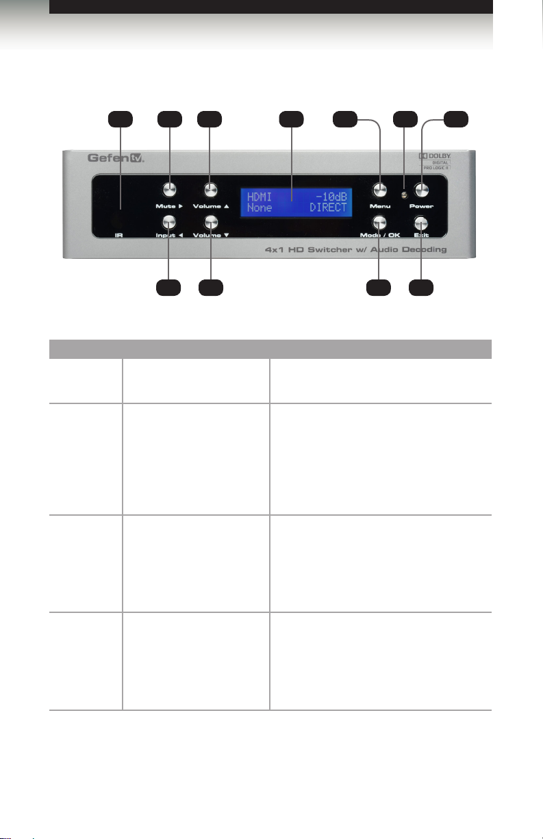
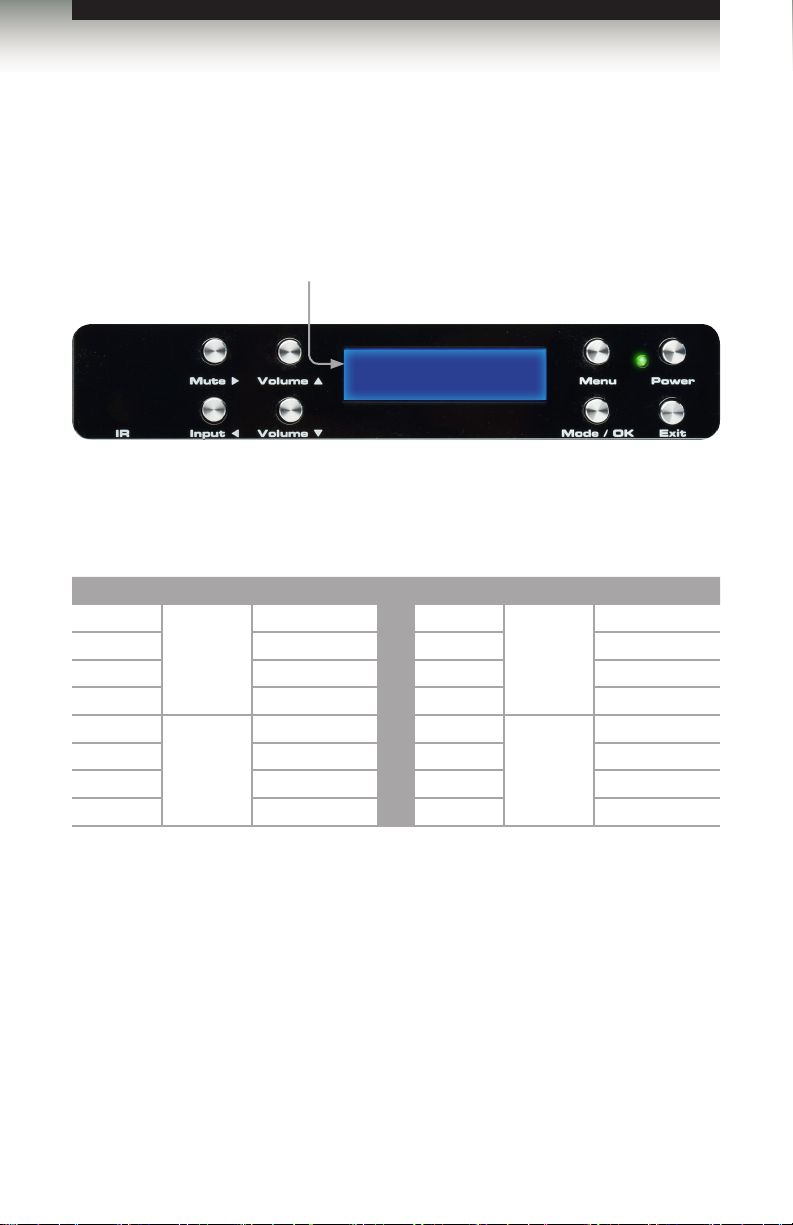
Front Panel
ID Name Description
1 IR This IR sensor receives commands from the
2 Mute ► This button will cycles between Mute-On and
1 2 4 6 9
3 5 8 10
included IR Remote Control Unit.
Mute-Off modes. When the Mute-On mode
is enabled, all audio output will be muted.
While in the Menu System this button will
cycle through available options in the right
direction when a feature has been selected
for adjustment.
117
3 Input ◄ Consecutively press this button to cycle
4 Volume ▲ Press this button to increase the volume
through each combination of video and
audio inputs. For each video input, audio
may be selected from the embedded HDMI
audio, coax, optical, or L/R analog audio
inputs.
level of the audio outputs. While in the
Menu System, this button is used to scroll
up through the current menu options.
See Using the Menu System for more
information.
page | 2
Page 13

Getting Started
Panel Layout
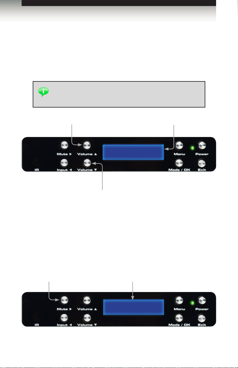
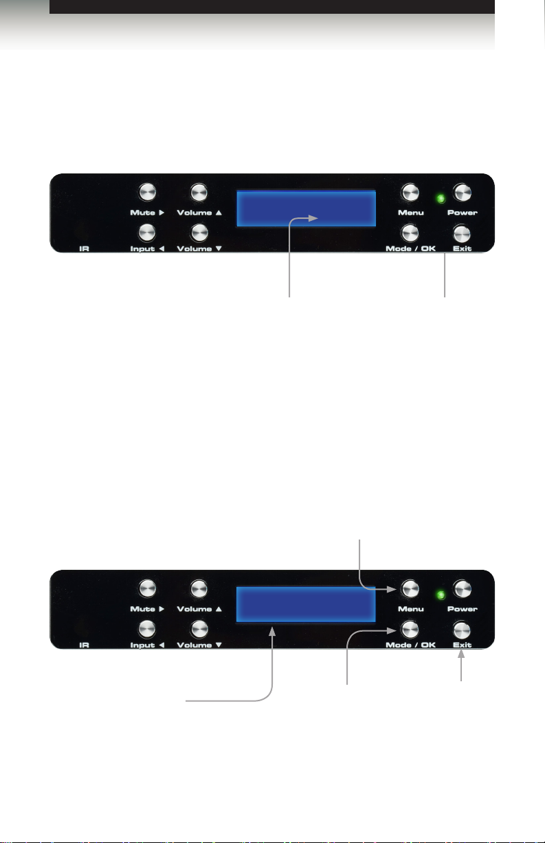
ID Name Description
5 Volume ▼ Press this button to decrease the volume
level of the audio outputs. While in the
Menu System, this button is used to scroll
down through the current menu options.
See Using the Menu System for more
information.
6 Front Panel Display The front-panel of the 4x1 HD Switcher w/
7 Menu Press this button to enter the Menu
8 Mode / OK Press this button to change the audio
9 Power Indicator This LED indicator will glow bright red
10 Exit Press this button to exit the current menu
11 Power Press this button to power ON the 4x1 HD
Audio Decoding contains a 16-character
2-line display which is used to provide
feedback when performing various
functions.
System. See Using the Menu System for
more information.
processing mode. See Setting the Audio
Processing Mode for more information.
when the unit is in standby mode.
When the unit is powered-on, this LED
indicator will glow bright green.
and return to the previous menu. See Using
the Menu System for more information.
Switcher w/ Audio Decoding or place it in
standby mode.
page | 3
Page 14
Getting Started
Panel Layout
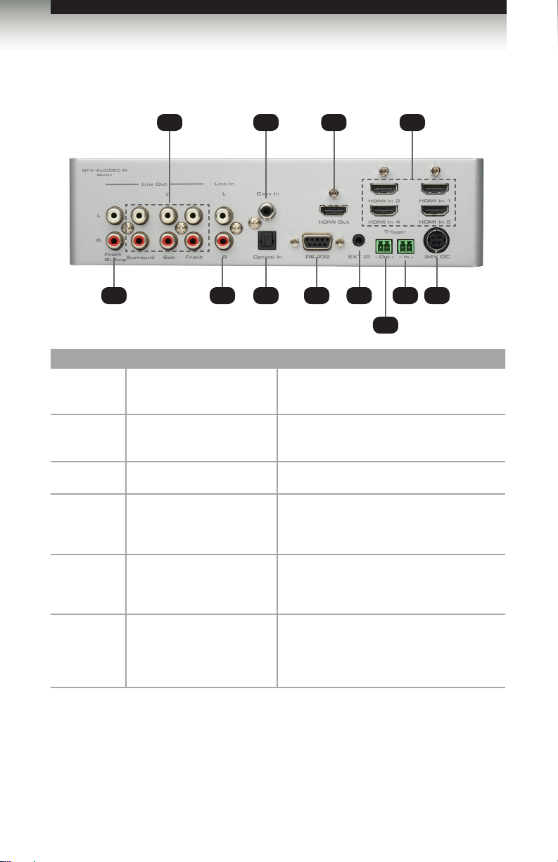
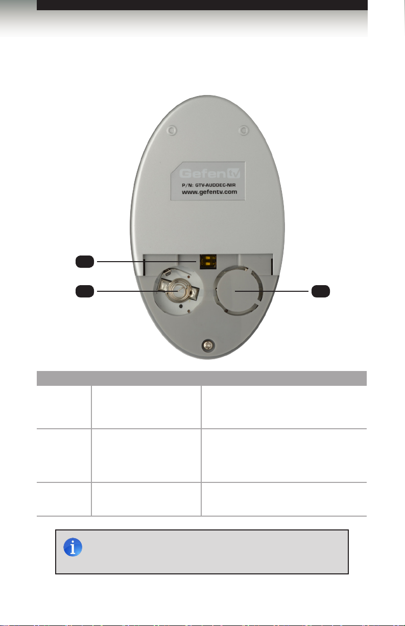
Back Panel
1 3 5 6 8 10912
ID Name Description
1 Line Out
(Front Bi-Amp)
2 Line Out
(Surround, C, Sub, Front)
3 Line In (L / R) L/R RCA-type audio inputs for analog audio.
42 7 11
These RCA connectors are only used in
Bi-Amp mode.
Use RCA cables to connect with an external
amplier.
4 Coax In Connect a coax audio cable between this
5 Optical In Use an optical cable between this TOSLINK
6 RS-232 Connect a RS-232 cable between this DB-9
S/PDIF connector and the S/PDIF connector
of a digital audio source.
connector and the TOSLINK connector of a
digital audio source.
connector and the RS-232 controller.
See RS-232 Conguration for more
information.
page | 4
Page 15

Getting Started
Panel Layout
ID Name Description
7 HDMI Out Connect an HDMI cable between this
connector and an HDTV display.
8 IR Ext Connect an IR Extender (Gefen part no.
9 Trigger (Out -/+) Provides 11.5 V DC when the Switch is
10 Trigger (In -/+) Used to externally power the unit ON
11 HDMI In (1 - 4) Connect up to four Hi-Def sources to these
12 24V DC Connect the included the 24V DC power
EXT-RMT-IREXTN) to this port to extend the
range of the IR remote control unit.
powered ON. This trigger can be used to
control an external power amplier, lights,
curtains, etc.
or OFF. This trigger will power ON the
Switcher when a 3 V - 12 V DC voltage is
applied. If the existing voltage is removed,
then the Switcher is placed in Standby
Mode (consumes less than < 1 W).
HDMI inputs using HDMI cables.
supply to this power receptacle. Only use
the power supply that is included with this
product.
page | 5
Page 16
Getting Started
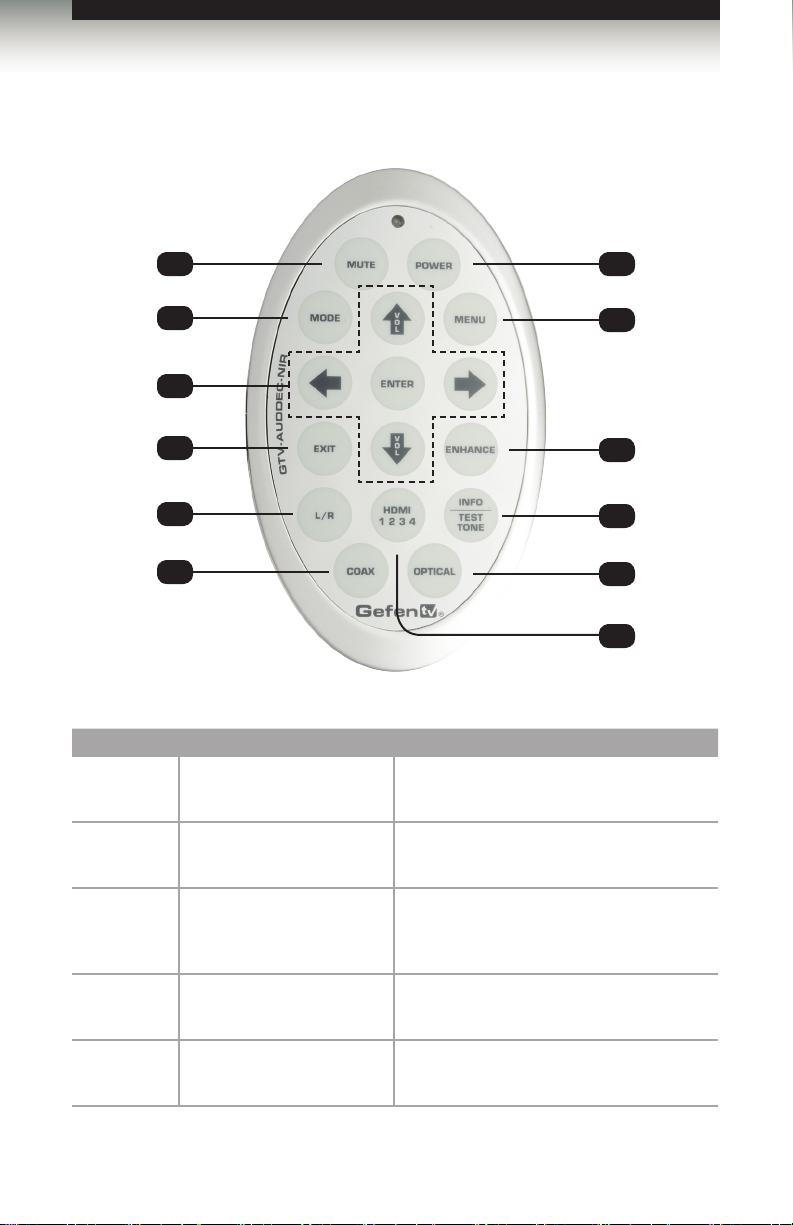
IR Remote Control Unit
1 7
Top
2
8
3
4
5
6
ID Name Description
1 MUTE Press this button to mute or unmute the
2 MODE Press this button to cycle through each of the
audio output.
available audio modes.
9
10
11
12
3
4 EXIT This button functions the same as the Exit
5 L / R Press this button to select the analog L/R
A/S/D/W/ENTER
These buttons are the equivalent of the
Input ◄, Volume ▼, Mute ►, Volume ▲,
and Mode / OK buttons on the front panel.
button on the front panel.
audio input source.
page | 6
Page 17

Getting Started
IR Remote Control Unit
ID Name Description
6 COAX Press this button to select the S/PDIF audio
input source.
7 POWER Press this button to toggle between power
8 MENU This button activates the Menu system.
9 ENHANCE This button will cycle through each of the
10 INFO / TEST TONE This button will display a series of information
11 OPTICAL Press this button to select the TOSLINK
12 HDMI 1 2 3 4 Consecutively press this button to cycle
ON and standby mode . The Power LED
indicator will indicate the current power state.
See Standby Mode / Powering the Switcher
for more information.
audio enhancement presets. See Audio
Enhancement Modes for more information
on this feature.
messages on the LCD screen when pressed.
When adjusting the Speaker Level, this
button will activate a test tone that is useful
for adjusting the volume level of each
speaker.
audio input source. The current video source
will not change.
through each of the HDMI inputs.
page | 7
Page 18
Getting Started
IR Remote Control Unit
(shown with cover removed)
Bottom
1
2
3
ID Name Description
1 DIP switch bank Use these DIP switches to set the IR
2 Primary battery slot
(shown without battery)
3 Alternate battery slot Allows for the installation of secondary
NOTE: An Activity Indicator that ashes quickly while holding down
any one of the buttons indicates a low battery. Replace the battery
as soon as possible.
channel of the remote. See Setting the
Remote IR Channel for details.
Holds the battery for operating the remote.
Use only 3V CR2032-type batteries. Make
sure that the positive (+) side of the battery
is facing up.
(backup) battery.
page | 8
Page 19
Getting Started
IR Remote Control Unit
Installing the Battery
The IR remote control unit ships with two batteries. Only one battery is required for
operation. The second battery is a spare. Use only 3V CR2032-type batteries.
1. Remove the back cover the IR Remote Control unit.
2. Insert the included battery into the primary battery slot. The positive (+) side of the
battery should be facing up.
3. Replace the back cover.
WARNING: Risk of explosion if battery is replaced by an incorrect
type. Dispose of used batteries according to the instructions.
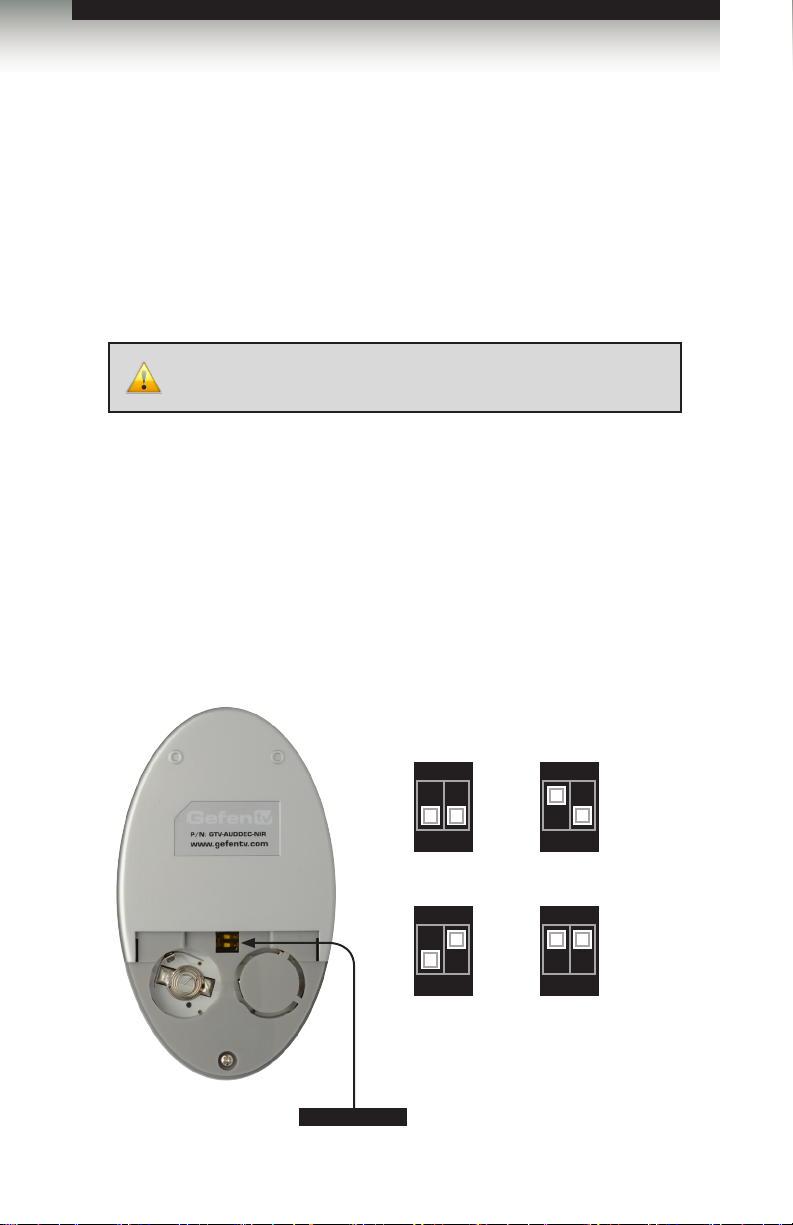
Setting the Remote IR Channel
In order for the included IR remote control to communicate with the 4x1 HD Switcher w/
Audio Decoding, the IR remote control must be set to the same channel as the processor.
See the section Setting the Switcher IR Channel or use the IR command to set the IR
channel of the 4x1 HD Switcher w/ Audio Decoding.
Channel 0 (default): Remote Channel 1:
ON
1 2ON1 21 2
Remote Channel 2: Remote Channel 3:
ON
1 2
ON
1 2
DIP switches
page | 9
Page 20
Getting Started
Installation
Connecting the 4x1 HD Switcher w/ Audio Decoding
1. Connect up to four Hi-Def sources to the HDMI In ports on the 4x1 HD Switcher
w/ Audio Decoding.
2. Connect additional audio sources to the Optical, Coax, and/or analog inputs, as
required.
3. Connect the Digital Audio Decoder to an amplier using the RCA connectors on the
rear panel. The following RCA connectors are available:
• Front Left
• Front Left (for bi-amping)
• Front Right
• Front Right (for bi-amping)
• Center
• Left Surround
• Right Surround
• Subwoofer
•
4. Connect an HDMI cable from the HDMI Out to a Hi-Def display.
5. Connect the included 24 V DC power supply to the power receptacle on the switcher.
6. Connect the AC power cord to an available electrical outlet.
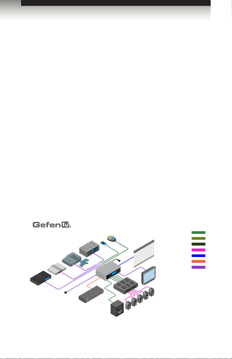
Sample Wiring Diagram
Digital Audio Source
Playing: SCALER WARS
LEVEL: 22
EISBRECHER
TRACK 2
GTV-AUDDEC-N
Powered Subwoofer
IR Extender
GTV-AUDDEC-N
Amplifier
SL
L
Electric Screen
R
C
GTV-AUDDEC-N
Blu-ray Player
Cable Box
STOP 1080p [DII]
SURROUND SOUNd
chp 4
Game Console
12V Source
(for trigger in)
VIDEO GAME MODE
Playing: SCALER WARS
LEVEL: 22
VIDEO GAME MODE
Playing: SCALER WARS
LEVEL: 22
MP3 Player
EXT-PACS
Home Theater PC
(Professional Automation Control System)
page | 10
L/R STEREO AUDIO CABLE
TOSLINK AUDIO CABLE
S/PDIF AUDIO CABLE
SPEAKER CABLE
TRIGGER CABLE
RS-232 CABLE
HDMI CABLE
HD Display
SR
Page 21

Page 22

Page 23

HD Switcher
x
4 1
SOURCES
02 Operating the
4x1 HD Switcher w/ Audio
Decoding
DISPLAYS
Front Panel Controls ........................................................................................... 14
Home Screen .............................................................................................. 14
Standby Mode / Powering the Switcher ...................................................... 14
Selecting the Input Source .......................................................................... 15
Adjusting the Volume .................................................................................. 16
Muting the Audio Output ............................................................................. 16
Changing the Audio Processing Mode ........................................................ 17
Accessing the Main Menu ........................................................................... 17
Using the Menu System ...................................................................................... 18
Setting the Speaker Size ............................................................................. 18
Setting the Speaker Levels ......................................................................... 20
Setting the Speaker Distance ...................................................................... 21
Adjusting the Tone Control .......................................................................... 23
Setting the Audio Processing Mode ............................................................ 25
Dynamic Range Compression .................................................................... 30
Audio Enhancement Modes ........................................................................ 32
Setting the Unit of Measurement ................................................................. 34
Setting the EDID Mode ............................................................................... 36
Setting the IR Channel ................................................................................ 38
Resetting to Factory-Default Settings ......................................................... 39
HDCP Setup ................................................................................................ 41
w/ Audio Decoding
Page 24
Operating the 4x1 HD Switcher w/ Audio Decoding
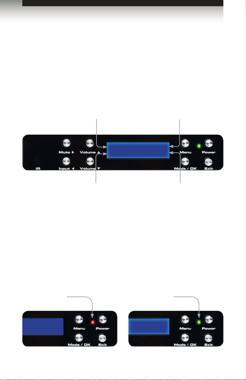
Front Panel Controls
Home Screen
The Home Screen displays information regarding the current settings of the Switcher.
The Home Screen is also used in conjunction with navigating the built-in Menu System.
After powering on the Switcher, the Home Screen will be displayed. The Home Screen
indicates the currently selected A/V input, the current volume setting, the audio input
format, and the audio processing mode:
Displays the currently selected
A/V Input
Audio and Video inputs
Input Format
Displays the
audio input format
H1 HD -10db
-
None Direct
Displays the current audio
Audio Gain
Displays the audio
gain (volume)
Audio Mode
processing mode
Standby Mode / Powering the Switcher
Once the power supply is connected and the AC power cord is connected to an available
electrical outlet, the Power Indicator will glow bright red. When the Power Indicator is red,
the Switcher is Standby Mode.
To power-on the Switcher, press the Power button on the front panel or use the Power
button on the IR Remote Control. The power indicator, next to the Power button, will glow
bright green.
Standby Mode
(Red LED)
Switcher Active
(Green LED)
-10db
Direct
page | 14
Page 25
Operating the 4x1 HD Switcher w/ Audio Decoding
Front Panel Controls
Selecting the Input Source
Press the Input ◄ button to cycle through each input source. The table below lists which
inputs are active for each selection.
The 4x1 HD Switcher w/ Audio Decoding has four HDMI inputs (1 - 4) and three options for
audio (coax, optical, and analog stereo). The following table lists the available video and
audio inputs.
Displays the currently
A/V Input
selected A/V input
H1 HD -10db
-
None Direct
Display Video Audio Display Video Audio
H1_HD HDMI In 1 HDMI H3_HD HDMI In 3 HDMI
H1_CX Coax H3_CX Coax
H1_OT Optical H3_OT Optical
H1_LR Analog L/R H3_LR Analog L/R
H2_HD HDMI In 2 HDMI H4_HD HDMI In 4 HDMI
H2_CX Coax H4_CX Coax
H2_OT Optical H4_OT Optical
H2_LR Analog L/R H4_LR Analog L/R
The currently displayed A/V input is abbreviated in the home screen, as follows:
[HDMI Input_Audio Source], where:
HDMI Input:
H1, H2, H3, and H4 represents each HD In port input on the back panel of the 4x1 HD
Switcher w/ Audio Decoding.
Audio Source:
• HD = Embedded HDMI audio
• CX = Coax (S/PDIF)
• OT = Optical (TOSLINK)
• LR = Analog L/R
page | 15
Page 26
Operating the 4x1 HD Switcher w/ Audio Decoding
Front Panel Controls
Adjusting the Volume
Use the Volume ▲ and Volume ▼ buttons to increase or decrease the audio output gain.
The ▲ or ▼ buttons on the IR Remote Control can also be used to control the audio output
gain. Audio gain can be reduced to a minimum of -60 dB and to a maximum of +10 dB.
Each time these buttons are pressed, the volume is increased or decreased by 1 dB.
TIP: To increase or decrease the audio gain at a faster rate, press
and hold down either the Volume ▲ or Volume ▼ button until the
desired volume is achieved.
Increase
Volume
H1 HD -10db
-
None Direct
Decrease
Volume
Current
Volume
Muting the Audio Output
Use the Mute button on the front panel or on the IR Remote Control to mute the audio
output. The display will indicate if the audio is muted. To disable the mute function, press
the Mute button again. The Volume ▲ and Volume ▼ buttons can also be used to disable
muting.
Mutes
Audio Output
Indicates
Audio is muted
H1 HD MUTE -10db
-
None Direct
page | 16
Page 27
Operating the 4x1 HD Switcher w/ Audio Decoding
Front Panel Controls
Changing the Audio Processing Mode
Successively press the Mode / OK button on the front panel to cycle through the different
audio processing modes. The Mode button on the IR Remote Control can also be used to
cycle through the audio modes.
H1 HD MUTE -10db
-
None Direct
See Setting the Audio Processing Mode for a description of each of the available audio
processing modes.
Displays
current audio
mode
Press to change
audio mode
Accessing the Main Menu
To access the Menu System, press the Menu button on the front panel. The front-panel
display will indicate that the menu system is active. The current sub-menu will be displayed
under “Main Menu”.
Sub-menu
Current
MAIN MENU
SPEAKER SIZE
Press to
access
sub-menu
Press to display
Menu system
Press to
return to
Home Screen
Press the Volume ▲ or Volume ▼ button to cycle through the different sub-menus. Press
the Mode / OK button to access the currently displayed sub-menu. Press the Exit button
to return to the home screen.
page | 17
Page 28

Operating the 4x1 HD Switcher w/ Audio Decoding
Using the Menu System
The 4x1 HD Switcher w/ Audio Decoding comes with a built-in menu system which provides
control over additional audio features. The following examples demonstrate some of the
more common features of the 4x1 HD Switcher w/ Audio Decoding.
Setting the Speaker Size
Speaker size is determined by the ability of a speaker to reproduce low frequencies.
When using a powered Subwoofer one should select speaker size to SMALL. If the Center,
Surrounds, or Subwoofer speakers are not connected, then turn these channels ‘off’.
(audio from these channels will be re-directed to the front speakers).
IMPORTANT: If the FL/FR speakers are bi-amped, then the
Speaker Size must be set to LARGE.
Using the front-panel buttons
1. Press the Menu button. The front-panel display will change to display the Speaker
Size menu:
MAIN MENU
SPEAKER SIZE
2. Press the Mode / OK button. The front-panel display will show the Front L / Front R
speaker size:
SPEAKER SIZE
FRONT L/R(LARGE)
3. Press the Mute ► or Input ◄ button to select the speaker size.
SPEAKER SIZE
FRONT L/R(SMALL)
4. Use the Volume ▲ or Volume ▼ buttons to congure the Center, Surround L / R,
and Subwoofer.
page | 18
Page 29

Operating the 4x1 HD Switcher w/ Audio Decoding
Using the Menu System
5. Press the Exit button to save the changes and return to the Speaker Size menu.
6. Press the Exit button a second time to return to the home screen.
H1 HD -30DB
-
NONE DIRECT
Using the IR Remote Control
1. Press the MENU button. The front-panel display will change to display the Speaker
Size menu:
MAIN MENU
SPEAKER SIZE
2. Press the ENTER button. The front-panel display will show the Front Left / Front R
speaker size:
SPEAKER SIZE
FRONT L/R(LARGE)
3. Press the ◄ or ► buttons to select the speaker size.
SPEAKER SIZE
FRONT L/R(SMALL)
4. Use the ▲ or ▼ buttons to congure the Center, Surround L / R, and Subwoofer.
5. Press the EXIT button to save the changes and return to the Speaker Size menu.
6. Press the EXIT button a second time to return to the home screen.
page | 19
Page 30

Operating the 4x1 HD Switcher w/ Audio Decoding
Using the Menu System
Setting the Speaker Levels
When using the IR Remote Control, the INFO | TEST TONE button is used to produce a
test tone to adjust the output level of each channel. The test tone can also be enabled or
disabled using the TEST command.
1. Press the MENU button. Press the ▼ button to navigate to the Speaker Level menu.
MAIN MENU
SPEAKER LEVEL
2. Press the ENTER button. The front-panel display will show the Front Left speaker
level:
SPEAKER LEVEL
FRONT L (+00db)
3. Press the INFO | TEST TONE button on the IR Remote Control to enable the test
tone.
4. Press the ◄ or ► buttons to adjust the output level of the Front Left speaker.
SPEAKER LEVEL
FRONT L (+02DB)
5. Use the ▲ or ▼ buttons to cycle through the Center, Front Right, Surround Right,
Surround Left, and Subwoofer and adjust the output level of each speaker as required.
The test tone is automatically disabled when advancing to the next speaker and will
need to be selected once again.
6. Press the EXIT button to save the changes and return to the Speaker Level menu.
MAIN MENU
SPEAKER LEVEL
7. Press the Exit button a second time to return to the home screen.
NOTE: The test tone will automatically be disabled when advancing
to the next channel. Press the INFO | TEST TONE button on the IR
Remote Control to enable the test tone.
page | 20
Page 31

Operating the 4x1 HD Switcher w/ Audio Decoding
Using the Menu System
Setting the Speaker Distance
Setting the correct speaker distance is required to make sure that the sounds from each
speaker reach your ear at precisely the same time. The distance for each speaker can be
set in 1.5 foot (0.5 meter) increments within a range of 0 feet - 33 feet (10 meters).
Speaker distance can be viewed in feet or meters. See Setting the Unit of Measurement
for more information.
Using the front-panel buttons
1. From the home screen, press the Menu button. Use the Volume ▲ or Volume ▼ but-
tons to navigate to the Speaker Distance menu:
MAIN MENU
SPEAKER DISTANCE
2. Press the Mode / OK button. The front-panel display will show the current distance
for the Front Left speaker:
SPEAKER DISTANCE
FRONT L (03.0M)
3. Press the Mute ► or Input ◄ button to change the distance of the Front Left speaker.
SPEAKER DISTANCE
FRONT L (04.5)
4. Use the Volume ▲ or Volume ▼ buttons to cycle through the Center, Front Right,
Surround Right, Surround Left, and Subwoofer and adjust the speaker distance as
necessary.
5. Press the Exit button to save the changes and return to the Speaker Distance menu.
MAIN MENU
SPEAKER DISTANCE
6. Press the Exit button a second time to return to the home screen.
H1 HD -30DB
-
NONE DIRECT
page | 21
Page 32

Operating the 4x1 HD Switcher w/ Audio Decoding
Using the Menu System
Using the IR Remote Control
1. From the home screen, press the MENU button. Use the ▲ or ▼ buttons to navigate
to the Speaker Distance menu:
MAIN MENU
SPEAKER DISTANCE
2. Press the ENTER button. The front-panel display will show the current distance for
the Front Left speaker:
SPEAKER DISTANCE
FRONT L (03.0M)
3. Press the ◄ or ► buttons to change the distance of the Front Left speaker.
SPEAKER DISTANCE
FRONT L (04.5)
4. Use the ▲ or ▼ buttons to cycle through the Center, Front Right, Surround Right,
Surround Left, and Subwoofer and adjust the speaker distance as necessary.
5. Press the EXIT button to save the changes and return to the Speaker Distance
menu.
MAIN MENU
SPEAKER DISTANCE
6. Press the Exit button a second time to return to the home screen.
H1 HD -30DB
-
NONE DIRECT
page | 22
Page 33

Operating the 4x1 HD Switcher w/ Audio Decoding
Using the Menu System
Adjusting the Tone Control
The Tone Control menu provides the ability to adjust the bass and treble to personal
preference. Treble and bass can be increased or decreased in 1 dB intervals, within a
range of -12 dB to +12 dB.
Using the front-panel buttons
1. From the home screen, press the Menu button. Use the Volume ▲ or
Volume ▼ buttons to select the Tone Control menu:
MAIN MENU
TONE CONTROL
2. Press the Mode / OK button. The front-panel display will show the current bass
setting.
TONE CONTROL
BASS (+01DB)
3. Press the Mute ► or Input ◄ button to change the bass setting.
TONE CONTROL
BASS (-02DB)
4. Use the Volume ▲ or Volume ▼ buttons to navigate to the Treble setting and adjust
the level as necessary, using the Mute ► or Input ◄ buttons.
TONE CONTROL
TREBLE (+05DB)
5. Press the Exit button to save the changes and return to the Tone Control menu.
6. Press the Exit button a second time to return to the home screen.
H1 HD -30DB
-
NONE DIRECT
page | 23
Page 34

Operating the 4x1 HD Switcher w/ Audio Decoding
Using the Menu System
Using the IR Remote Control
1. From the home screen, press the MENU button. Use the ▲ or ▼ buttons to select the
Tone Control menu:
MAIN MENU
TONE CONTROL
2. Press the ENTER button. The front-panel display will show the current bass setting.
TONE CONTROL
BASS (+01DB)
3. Press the ◄ or ► button to change the bass setting.
TONE CONTROL
BASS (-02DB)
4. Use the ▲ or ▼ buttons to navigate to the Treble setting and adjust the level as
necessary.
TONE CONTROL
TREBLE (+05DB)
5. Press the EXIT button to save the changes and return to the Tone Control menu.
6. Press the Exit button a second time to return to the home screen.
H1 HD -30DB
-
NONE DIRECT
page | 24
Page 35

Operating the 4x1 HD Switcher w/ Audio Decoding
Using the Menu System
Setting the Audio Processing Mode
The 4x1 HD Switcher w/ Audio Decoding, allows any of ve audio processing modes to be
associated with a selected input.
For example, you may want to select the Multichannel Stereo audio processing mode
with the optical (TOSLINK) input. On the other hand, you may want to select the Dolby®
Pro Logic II (PLII) audio processing mode when using the analog L/R inputs, in order to
transform two-channel content into surround sound. These two examples will be illustrated.
Available Modes
Mode Description
DIRECT
Audio playback without any processing (default setting). The input
signal is the same as the output signal.
STEREO
MCH STER
MONO
PLII
Multichannel audio is down-mixed into two channels.
This mode will output unprocessed stereo sound equally from all
your speakers.
2 or more channels are down-mixed into mono.
Transforms stereo content into 5-channel surround sound.
NOTE: PLII (Dolby Pro Logic II) Mode processes two-channel
content into ve separate full-frequency channels.
page | 25
Page 36

Operating the 4x1 HD Switcher w/ Audio Decoding
Using the Menu System
Using the front panel buttons
Example 1: Assigning the optical (TOSLINK) input with the Multichannel Stereo audio
processing mode:
1. From the home screen, press the Menu button. Use the Volume ▲ or Volume ▼
buttons to navigate to the Audio Setup menu:
MAIN MENU
AUDIO SETUP
2. Press the Mode / OK button. The front-panel display will display the coaxial option:
AUDIO SETUP
COAXIAL FAV PROC
3. Use the Volume ▼ button to navigate to the optical option:
AUDIO SETUP
OPTICAL FAV PROC
4. Press the Mute ► or Input ◄ button to access the current setting for the optical
(TOSLINK) input. In the illustration below, the optical input is set to use the Direct audio
processing mode, by default:
OPTICAL FAV PROC
OPTIL ( DIRECT )
5. Press the Mute ► or Input ◄ button to change the current (favorite) setting. In the
example below, we have set the optical input to use the Multichannel Stereo audio
processing mode:
OPTICAL FAV PROC
OPTIL (MCH STER)
6. Press the Exit button to save the changes and return to the Audio Setup menu.
(continued on next page)
page | 26
Page 37

Operating the 4x1 HD Switcher w/ Audio Decoding
Using the Menu System
Example 2: Assigning the analog L/R inputs with the Dolby Pro Logic II audio processing
mode:
1. Starting from Step 5, on the previous page, use the Volume ▼ button to select the
analog L/R option:
AUDIO SETUP
AUD LR FAV PROC
2. Press the Mute ► or Input ◄ button to access the current setting for the analog L/R
input. In the illustration below, the analog L/R input is set to use the Stereo audio
processing mode:
AUD LR FAV PROC
AUD LR( STEREO )
3. Press the Mute ► or Input ◄ button to change the current (favorite) setting from Stereo
to PLII (Dolby Pro Logic II):
AUD LR FAV PROC
AUD LR( PLII )
4. Press the Exit button to save all changes and return to the Audio Setup menu.
MAIN MENU
AUDIO SETUP
5. Press the Exit button a second time to return to the home screen.
H1 HD -30DB
-
NONE DIRECT
page | 27
Page 38

Operating the 4x1 HD Switcher w/ Audio Decoding
Using the Menu System
Using the IR Remote Control
Example 1: Assigning the optical (TOSLINK) input with the Multichannel Stereo audio
processing mode:
1. From the home screen, press the MENU button. Use the ▲ or ▼ buttons to select the
Audio Setup menu:
MAIN MENU
AUDIO SETUP
2. Press the ENTER button. The front-panel display will display the coaxial option:
AUDIO SETUP
COAXIAL FAV PROC
3. Use the ▼ button to navigate to the optical option:
AUDIO SETUP
OPTICAL FAV PROC
4. Press the ► or ◄ button to access the current setting for the optical (TOSLINK) input.
In the illustration below, the optical input is set to use the Direct audio processing mode,
by default:
OPTICAL FAV PROC
OPTIL ( DIRECT )
5. Press the ► or ◄ button to change the current (favorite) setting. In the example below,
we have set the optical input to use the Multichannel Stereo audio processing mode:
OPTICAL FAV PROC
OPTIL (MCH STER)
6. Press the EXIT button to save the changes and return to the Audio Setup menu.
(continued on next page)
page | 28
Page 39

Operating the 4x1 HD Switcher w/ Audio Decoding
Using the Menu System
Using the IR Remote Control (continued)
Example 2: Assigning the analog L/R inputs with the Dolby® Pro Logic II audio processing
mode:
1. Starting from Step 5, on the previous page, use the ▼ button to select the analog L/R
option:
AUDIO SETUP
AUD LR FAV PROC
2. Press the ► or ◄ button to access the current setting for the analog L/R input. In the
illustration below, the analog L/R input is set to use the Stereo audio processing mode:
AUD LR FAV PROC
AUD LR( STEREO )
3. Press the ► or ◄ button to change the current (favorite) setting from Stereo to PLII
(Dolby® Pro Logic II):
AUD LR FAV PROC
AUD LR( PLII )
4. Press the Exit button to save all changes and return to the Audio Setup menu.
MAIN MENU
AUDIO SETUP
5. Press the Exit button a second time to return to the home screen.
H1 HD -30DB
-
NONE DIRECT
page | 29
Page 40

Operating the 4x1 HD Switcher w/ Audio Decoding
Using the Menu System
Dynamic Range Compression
Dynamic Range Compression (DRC) applies compression to the output signal, preventing
the signal from becoming too loud. The default setting for Dynamic Range Compression is
OFF.
Using the front-panel buttons
1. From the home screen, press the Menu button.
2. Use the Volume ▲ or Volume ▼ buttons to navigate to the Audio Setup menu.
MAIN MENU
AUDIO SETUP
3. Press the Mode / OK button.
4. Use the Volume ▲ or Volume ▼ buttons to select the DRC option:
AUDIO SETUP
DRC ( OFF )
5. Press the ◄ or ► button to change to enable DRC.
AUDIO SETUP
DRC ( ON )
6. Press the Exit button to save the changes and return to the Audio Setup menu.
MAIN MENU
AUDIO SETUP
7. Press the Exit button a second time to return to the home screen.
H1 HD -30DB
-
NONE DIRECT
(continued on next page)
page | 30
Page 41

Operating the 4x1 HD Switcher w/ Audio Decoding
Using the Menu System
Using the IR Remote Control
1. From the home screen, press the MENU button.
2. Use the ▲ or ▼ buttons to navigate to the Audio Setup menu.
MAIN MENU
AUDIO SETUP
3. Press the ENTER button.
4. Use the ▲ or ▼ buttons to select the DRC option:
AUDIO SETUP
DRC ( OFF )
5. Press the ◄ or ► button to change to enable DRC.
AUDIO SETUP
DRC ( ON )
6. Press the EXIT button to save the changes and return to the Audio Setup menu.
MAIN MENU
AUDIO SETUP
7. Press the Exit button a second time to return to the home screen.
H1 HD -30DB
-
NONE DIRECT
page | 31
Page 42

Operating the 4x1 HD Switcher w/ Audio Decoding
Using the Menu System
Audio Enhancement Modes
The 4x1 HD Switcher w/ Audio Decoding provides four distinct audio enhancement modes.
Each of these modes provide a different audio listening experience.
Available Modes
Mode (LCM display) Description
NIGHT
Increases the volume of quiet passages, while decreasing the
volume of loud passages. Similar to DRC but works with all audio
signals.
VOICE
VOLUME
OFF
Detects speech audio patterns and separates them from the
background sounds, making them more legible.
Real-time detection of the source audio gain, providing constant
volume level between changing channels and commercial
advertisements.
Disables audio enhancement mode.
Using the front-panel buttons
1. From the home screen, press the Menu button.
2. Use the Volume ▲ or Volume ▼ buttons to navigate to the Audio Setup menu.
MAIN MENU
AUDIO SETUP
3. Press the Mode / OK button.
4. Use the Volume ▲ or Volume ▼ buttons to select the Enhancement option:
AUDIO SETUP
ENHA. ( OFF )
(continued on next page)
page | 32
Page 43

Operating the 4x1 HD Switcher w/ Audio Decoding
Using the Menu System
5. Press the ◄ or ► button to change to change the audio enhancement mode. In the
illustration below, the audio enhancement mode has been set to Night mode:
AUDIO SETUP
ENHA. ( NIGHT+ )
6. Press the Exit button to save the changes and return to the Audio Setup menu.
7. Press the Exit button a second time to return to the home screen.
H1 HD -30DB
NONE DIRECT
Using the IR Remote Control
1. From the home screen, press the MENU button.
2. Use the ▲ or ▼ buttons to navigate to the Audio Setup menu.
MAIN MENU
AUDIO SETUP
3. Press the ENTER button.
4. Use the ▲ or ▼ buttons to select the Enhancement option:
AUDIO SETUP
ENHA. ( OFF )
5. Press the ◄ or ► button to change to change the audio enhancement mode. In the
illustration below, the audio enhancement mode has been set to Night mode:
AUDIO SETUP
ENHA. ( NIGHT+ )
6. Press the EXIT button to save the changes and return to the Audio Setup menu.
7. Press the EXIT button a second time to return to the home screen.
page | 33
Page 44

Operating the 4x1 HD Switcher w/ Audio Decoding
Using the Menu System
Setting the Unit of Measurement
When adjusting the speaker distance, either feet or meters can be specied.
Using the front-panel buttons
1. From the home screen, press the Menu button. Use the Volume ▲ or Volume ▼
buttons to navigate to the Misc Setup menu.
MAIN MENU
MISC SETUP
2. Press the Mode / OK button. The front-panel display will show the current distance
for the Front Left speaker:
In the illustration below, the current unit of measure is currently set to meters.
MAIN MENU
DIST.UNIT(METER)
3. To change the unit of measure to feet, press the Mute ► or Input ◄ button to change
the unit of measure to feet.
MAIN MENU
DIST.UNIT(FEET)
4. Press the Exit button to save the changes and return to the Misc Setup menu.
5. Press the Exit button a second time to return to the home screen.
H1 HD -30DB
-
NONE DIRECT
(continued on next page)
page | 34
Page 45

Operating the 4x1 HD Switcher w/ Audio Decoding
Using the Menu System
Using the IR remote control
1. From the home screen, press the MENU button. Use the ▲ or ▼ buttons to
select the Misc Setup menu.
MAIN MENU
MISC SETUP
2. Press the ENTER button. The front-panel display will show the current distance for
the Front Left speaker:
In the illustration below, the current unit of measure is currently set to meters.
MAIN MENU
DIST.UNIT(METER)
3. To change the unit of measure to feet, press the ► or ◄ button to change the unit of
measure to feet.
MAIN MENU
DIST.UNIT(FEET)
4. Press the EXIT button to save the changes and return to the Misc Setup menu.
5. Press the EXIT button a second time to return to the home screen.
H1 HD -30DB
-
NONE DIRECT
page | 35
Page 46

Operating the 4x1 HD Switcher w/ Audio Decoding
Using the Menu System
Setting the EDID Mode
The 4x1 HD Switcher w/ Audio Decoding has three EDID modes (INT, EXT, and MIX).
• INT Mode
The internal (local) EDID is used instead of the EDID from the display device. EDID
features newer than HDMI 1.3 are removed from the EDID data structure when the
display is read. This provides a general EDID which is compatible with more displays.
• EXT Mode
The external (downstream) EDID is used. In this mode, both DDC and HPD are
passed through and the 4x1 HD Switcher w/ Audio Decoding uses the full video
capabilities of the display. The HPD status will also be detected by the source device.
• MIX Mode
The display capabilities from the external EDID are combined with the audio
capabilities of the internal EDID of the 4x1 HD Switcher w/ Audio Decoding.
Using the front-panel buttons
1. To set the EDID mode, press the Menu button from the home screen.
2. Use the Volume ▲ or Volume ▼ buttons to navigate to the Misc Setup menu.
MAIN MENU
MISC SETUP
3. Press the Mode / OK button.
4. Use the Volume ▲ or Volume ▼ buttons to select the EDID Adjustment menu.
MISC SETUP
EDID ADJ.( INT )
5. Press the Mute ► or Input ◄ buttons to the desired EDID mode.
MISC SETUP
EDID ADJ.( MIX )
6. Press the Exit button to save the changes and return to the Misc Setup menu.
7. Press the Exit button a second time to return to the home screen.
(continued on next page)
page | 36
Page 47

Operating the 4x1 HD Switcher w/ Audio Decoding
Using the Menu System
Using the IR Remote Control
1. To set the EDID mode, press the MENU button from the home screen.
2. Use the ▲ or ▼ buttons to navigate to the Misc Setup menu.
MAIN MENU
MISC SETUP
3. Press the ENTER button.
4. Use the ▲ or ▼ button to select the EDID adjustment menu. In the example, below,
the internal (INT) EDID is being used.
MISC SETUP
EDID ADJ.( INT )
5. To change the EDID mode, press the ◄ or ► button to the desired EDID mode.
In the example, below, the mixed-mode EDID has been selected.
MISC SETUP
EDID ADJ.( MIX )
6. Press the EXIT button to save the changes and return to the Misc Setup menu.
7. Press the EXIT button a second time to return to the home screen.
page | 37
Page 48

Operating the 4x1 HD Switcher w/ Audio Decoding
Using the Menu System
Setting the Switcher IR Channel
When controlling the 4x1 HD Switcher w/ Audio Decoding using the IR Remote Control
Unit, the IR channel on the 4x1 HD Switcher w/ Audio Decoding must be the same as the
IR channel set on the IR Remote Control Unit. See Setting the Remote IR Channel for
instructions on setting the IR channel on the IR Remote Control Unit.
Using the front-panel buttons
1. From the home screen, press the Menu button.
2. Use the Volume ▲ or Volume ▼ buttons to navigate to the Misc Setup menu.
MAIN MENU
MISC SETUP
3. Press the Mode / OK button.
4. Use the Volume ▲ or Volume ▼ buttons to select the IR channel menu. In the
illustration below, the IR channel is set to 1.
MISC SETUP
IR CHANNEL ( 1 )
5. Press the Mute ► or Input ◄ buttons to change to the required IR channel.
MISC SETUP
IR CHANNEL ( 3 )
6. Press the Exit button to save the changes and return to the Misc Setup menu.
7. Press the Exit button a second time to return to the home screen.
page | 38
Page 49

Operating the 4x1 HD Switcher w/ Audio Decoding
Using the Menu System
Resetting to Factory-Default Settings
If the 4x1 HD Switcher w/ Audio Decoding needs to be reset for any reason or if you need
to set the unit to factory (default) settings, follow the instructions below.
Using the front-panel buttons
1. From the home screen, press the Menu button.
2. Use the Volume ▲ or Volume ▼ buttons to navigate to the Misc Setup menu.
MAIN MENU
MISC SETUP
3. Press the Mode / OK button.
4. Use the Volume ▲ or Volume ▼ buttons to select the Factory Defaults
option.
MISC SETUP
FACTORY DEFAULT
5. Press the Mode / OK button. The unit will prompt you to conrm the selection.
OK TO F.DEFAULT
MENU TO CANCEL
• To Reset: Press the Mode / OK button to reset the unit to factory (default)
settings. If the unit is reset, the 4x1 HD Switcher w/ Audio Decoding will power
OFF
and then automatically power ON after a few moments.
• To Cancel: Press the Menu button to cancel the reset process and return to the
home screen.
page | 39
Page 50

Operating the 4x1 HD Switcher w/ Audio Decoding
Using the Menu System
Using the IR remote control
1. From the home screen, press the MENU button.
2. Use the ▲ or ▼ buttons to navigate to the Misc Setup menu.
MAIN MENU
MISC SETUP
3. Press the Mode / OK button.
4. Use the Volume ▲ or Volume ▼ buttons to select the Factory Default option.
MISC SETUP
FACTORY DEFAULT
5. Press the ENTER button. The unit will prompt you to conrm the selection.
OK TO F.DEFAULT
MENU TO CANCEL
• To Reset: Press the Mode / OK button to reset the unit to factory (default)
settings. If the unit is reset, the 4x1 HD Switcher w/ Audio Decoding will power
OFF
and then automatically power ON after a few moments.
• To Cancel: Press the Menu button to cancel the reset process and return to the
home screen.
page | 40
Page 51

Operating the 4x1 HD Switcher w/ Audio Decoding
Using the Menu System
HDCP Setup
The HDCP Setup submenu provides the option to disable HDCP detection on the selected
input. Some sources (such as computers) will enable HDCP if an HDCP-compliant display
is detected. Each HDMI input can be set to ON (enable) or OFF (disable). Set the input to
ON to force the source device to ignore detection of an HDCP-compliant display.
1. From the home screen, press the Menu button.
2. Use the Volume ▲ or Volume ▼ buttons to navigate to the Misc Setup menu.
MAIN MENU
MISC SETUP
NOTE: Forcing the source device to ignore the detection of an
HDCP-compliant display does not decrypt HDCP content.
Using the front-panel buttons
3. Press the Mode / OK button.
4. Use the Volume ▲ or Volume ▼ buttons to select the HDCP Setup option.
MISC SETUP
HDCP SETUP
5. Press the Mode / OK button. The current setting for Input 1 (HD In 1) will be
displayed.
HDCP SETUP
INPUT-1 ( ON )
6. Press the Mute ► or Input ◄ buttons to change to switch between ON or OFF.
HDCP SETUP
INPUT-1 ( OFF )
(continued on next page)
page | 41
Page 52

Operating the 4x1 HD Switcher w/ Audio Decoding
Using the Menu System
7. Use the Volume ▲ or Volume ▼ buttons to select the next input.
8. Repeat steps 6 - 7 as necessary.
9. Press the Exit button to save the changes and return to the Misc Setup menu.
10. Press the Exit button a second time to return to the home screen.
Using the IR remote control
1. From the home screen, press the MENU button.
2. Use the ▲ or ▼ buttons to navigate to the Misc Setup menu.
MAIN MENU
MISC SETUP
3. Press the ENTER button.
4. Use the ▲ or ▼ buttons to select the HDCP Setup option.
MISC SETUP
HDCP SETUP
5. Press the ENTER button. The current setting for Input 1 (HDMI In 1) will be
displayed.
HDCP SETUP
INPUT-1 ( ON )
6. Press the ► or ◄ buttons to change to switch between ON or OFF.
HDCP SETUP
INPUT-1 ( OFF )
7. Use the ▲ or ▼ buttons to select the next input.
8. Repeat steps 6 - 7 as necessary.
9. Press the EXIT button to save the changes and return to the Misc Setup menu.
10. Press the EXIT button a second time to return to the home screen.
page | 42
Page 53

Page 54

Page 55

HD Switcher
x
4 1
SOURCES
03 Advanced Operation
DISPLAYS
RS-232 Conguration .......................................................................................... 46
RS-232 Interface ......................................................................................... 46
RS-232 Settings .......................................................................................... 46
RS-232 Commands ............................................................................................. 47
w/ Audio Decoding
Page 56

Advanced Operation
DE-9
RS-232 Conguration
RS-232 Interface
564738291
RS-232 Controller AV Processor
DCD
RXD
TXD
DTR
GND
DSR
RTS
CTS
R1
1
2
3
4
5
6
7
8
9
Only TXD, RXD, and GND pins are used.
RS-232 Settings
Description Setting
Baud rate
Data bits
Parity
Stop bits
Hardware ow control
19200
8
None
1
None
1
2
3
4
5
6
7
8
9
DCD
RXD
TXD
DTR
GND
DSR
RTS
CTS
R1
IMPORTANT: When sending RS-232 commands, a carriage return
must be included at the end of the command. A space must be
included between the command and the parameter.
page | 46
Page 57

Advanced Operation
RS-232 Commands
Command Description
AUDIO
BASS
CT
DC
DFL
DFLT
DFR
DRC
DSB
DSL
DSR
EDID
ENH
FLR
HDMI
HELP
INFO
INTYPE
IR
MD
MUTE
PWR
SLR
STAT
SUB
SUBV
TEST
TREB
TVTYPE
VOL
Selects between S/PDIF, TOSLINK, or Analog audio input
Increases or decreases the bass
Sets the size of the Center speaker
Sets the distance for the Center speaker
Sets the distance for the Front Left speaker
Sets the 4x1 HD Switcher w/ Audio Decoding to factory
(default) settings
Sets the distance for the Front Right speaker
Adjusts the Dynamic Range Control
Sets the distance for the Subwoofer
Sets the distance of the Left Surround speaker
Sets the distance of the Right Surround speaker
Sets the EDID mode
Sets the audio enhancement mode
Sets the size of the Front Left / Front Right speakers
Set the HDMI input
Lists these RS-232 commands
Returns hardware and rmware version
Returns the input audio format
Sets the IR channel for the 4x1 HD Switcher w/ Audio Decoding
Sets the audio mode
Enables / disables audio muting
Powers the 4x1 HD Switcher w/ Audio Decoding ON or OFF
Sets the size of the Surround Left and Surround Right speakers
Enables or disables auto status feedback
Enables / disables the subwoofer
Adjusts the subwoofer volume
Plays a test tone to specied speaker zone
Increases / decreases the treble
Sets the video broadcast format
Increases / decreases the overall output volume
NOTE: RS-232 commands are case-sensitive and must be entered
in all capital letters.
page | 47
Page 58

Advanced Operation
RS-232 Commands
AUDIO
The AUDIO command selects between S/PDIF, TOSLINK, or analog audio inputs.
The currently selected video input is unaffected.
Syntax:
AUDIO param1
Parameters:
param1 Value [0 ... 3]
Value Description
0
1
2
3
HDMI
S/PDIF (coax)
TOSLINK (optical)
Analog L/R
To return the current audio input, use the following command syntax:
AUDIO ?
Note:
When the AUDIO command is executed, the return value will be a two-digit value. The rst
number represents the current video input. The second number represents the audio input.
In the example below, the return value is HDMI 11. This value indicates that HDMI 1 is the
current video input and that S/PDIF is the selected audio input. The query value will always
be a two-digit value but only returns the current audio input.
Examples:
AUDIO 1
> HDMI 11
AUDIO ?
> AUDIO +01
page | 48
Page 59

Advanced Operation
RS-232 Commands
BASS
The BASS command sets the bass level.
Syntax:
BASS param1
Parameters:
param1 Value (dB) [-12 ... 12]
To return the current audio input, use the following command syntax:
BASS ?
Note:
The + or - character can also be used, instead of specifying a value, in order to
increase or decrease the bass level by 1 dB.
Examples:
BASS 5
> BASS +05
BASS ?
> BASS +05
BASS +
> BASS +06
BASS -
> BASS +05
page | 49
Page 60

Advanced Operation
RS-232 Commands
CT
The CT command sets the size of the Center speaker.
Syntax:
CT param1
Parameters:
param1 Value [0 ... 2]
Value Description
0
1
2
To return the current size setting for the Center speaker, use the following command
syntax:
CT ?
Small
Large
Off (disable Center speaker)
Examples:
CT 1
> CT +01
CT ?
> CT +01
page | 50
Page 61

Advanced Operation
RS-232 Commands
DC
The DC command sets the distance of the Center speaker.
Syntax:
DC param1
Parameters:
param1 Distance (feet) [0 ... 20]
To return the current distance setting of the Center speaker, use the following
command syntax:
DC ?
Examples:
DC 5
> DC 5
DC ?
> DC 5
page | 51
Page 62

Advanced Operation
RS-232 Commands
DFL
The DFL command sets the distance of the Front Left speaker.
Syntax:
DFL param1
Parameters:
param1 Distance (feet) [0 ... 20]
To return the current distance setting of the Front Left speaker, use the following
command syntax:
DFL ?
Examples:
DFL 10
> DC 10
DFL ?
> DFL 10
page | 52
Page 63

Advanced Operation
RS-232 Commands
DFLT
The DFLT command sets the 4x1 HD Switcher w/ Audio Decoding to the factory-default
settings.
Syntax:
DFLT 1
Parameters:
The value of 1 must be specied as part of this command.
No return value is available.
Example:
DFLT 1
> DFLT 1> PWR +00
> PWR +01
page | 53
Page 64

Advanced Operation
RS-232 Commands
DFR
The DFR command sets the distance of the Front Right speaker.
Syntax:
DFR param1
Parameters:
param1 Distance (feet) [0 ... 20]
To return the current distance setting of the Front Right speaker, use the following
command syntax:
DFR ?
Examples:
DFR 10
> DFR 10
DFR ?
> DFR 10
page | 54
Page 65

Advanced Operation
RS-232 Commands
DRC
The DRC command enables / disables Dynamic Range Control.
Syntax:
DRC param1
Parameters:
param1 Value [0 ... 1]
Value Description
0
1
To return the current DRC state, use the following command syntax:
DRC ?
DRC Off
DRC On
Example:
DRC 0
> DRC +00
page | 55
Page 66

Advanced Operation
RS-232 Commands
DSB
The DSB command sets the distance of the Subwoofer.
Syntax:
DSB param1
Parameters:
param1 Distance (feet) [0 ... 20]
To return the current distance setting of the Subwoofer, use the following command syntax:
DSB ?
Examples:
DSB 6
> DSB 6
DSB ?
> DSB 6
page | 56
Page 67

Advanced Operation
RS-232 Commands
DSL
The DSL command set the distance of the Surround Left speaker.
Syntax:
DSL param1
Parameters:
param1 Distance (feet) [0 ... 20]
To return the current distance setting of the Surround Left speaker, use the following
command syntax:
DSL ?
Examples:
DSL 2
> DSL 2
DSL ?
> DSL 2
page | 57
Page 68

Advanced Operation
RS-232 Commands
DSR
The DSR command set the distance of the Surround Right speaker.
Syntax:
DSR param1
Parameters:
param1 Distance (feet) [0 ... 20]
To return the current distance setting of the Surround Right speaker, use the following
command syntax:
DSR ?
Examples:
DSR 2
> DSR 2
DSR ?
> DSR 2
page | 58
Page 69

Advanced Operation
RS-232 Commands
EDID
The EDID command sets the EDID mode. The 4x1 HD Switcher w/ Audio Decoding will
automatically power-cycle after the command has been executed.
Syntax:
EDID param1
Parameters:
param1 Mode [0 ... 2]
Value Description
0
1
2
To return the current distance setting of the Surround Right speaker, use the following
command syntax:
EDID ?
EDID Mix
Internal EDID
External EDID
Note:
The EDID Mix Mode will use the full video capabilities of the display and combine the full
audio capabilities of the Internal EDID of the 4x1 HD Switcher w/ Audio Decoding.
Internal EDID will use the built-in EDID of the 4x1 HD Switcher w/ Audio Decoding.
External EDID uses the down-stream EDID of the display.
Examples:
EDID 1
> EDID +01
> PWR +00
> PWR +01
EDID ?
> EDID +01
page | 59
Page 70

Advanced Operation
RS-232 Commands
ENH
The ENH command set the audio enhancement mode. See Audio Enhancement Modes for
more information on this feature.
Syntax:
ENH param1
Parameters:
param1 Mode [0 ... 3]
Value Description
0
1
2
3
Night Mode
Voice Mode
Volume Mode
Off
To return the current audio enhancement mode setting, use the following command syntax:
ENH ?
Examples:
ENH 3
> ENH +03
ENH ?
> ENH +03
page | 60
Page 71

Advanced Operation
RS-232 Commands
FLR
The FLR command sets the size of the Front Left / Front Right speakers.
Syntax:
FLR param1
Parameters:
param1 Value [0 ... 1]
Value Description
0
1
To return the current size setting for the Front Left / Front Right speakers, use the following
command syntax:
FLR ?
Small
Large
Examples:
FLR 1
> FLR +01
FLR ?
> FLR +01
page | 61
Page 72

Advanced Operation
RS-232 Commands
HDMI
The HDMI command sets the active HDMI input. This command does not affect the current
audio input.
Syntax:
HDMI param1
Parameters:
param1 Value [1 ... 4]
Value Description
0
1
2
3
HDMI In 1
HDMI In 2
HDMI In 3
HDMI In 4
To return the current video input, use the following command syntax:
HDMI ?
Note:
When the HDMI command is executed, the return value will be a two-digit value. The rst
number represents the current video input. The second number represents the audio input.
In the example below, the return value is HDMI 21. This value indicates that HDMI In 2 is
the current video input and that S/PDIF is the selected audio input. The query value will
always be a two-digit value but only returns the current video input.
Examples:
HDMI 2
> HDMI 21
HDMI ?
> HDMI +02
page | 62
Page 73

Advanced Operation
RS-232 Commands
HELP
The HELP command displays a list of the available RS-232 commands.
Syntax:
HELP ?
Parameters:
The ? character must be specied as part of this command.
Example:
HELP ?
> COMMAND LIST :PWR
AUDIO
BASS
CT
DC
DFL
DFLT
DFR
DRC
DSB
DSL
DSR
EDID
ENH
FLR
HDMI
INFO
INTYPE
IR
MD
MUTE
SLR
SUB
SUBV
TEST
TREB
TVTYPE
VOL
page | 63
Page 74

Advanced Operation
RS-232 Commands
INFO
The INFO command returns the current hardware and rmware version.
Syntax:
INFO ?
Parameters:
The ? character must be specied as part of this command.
Example:
INFO ?
> FW 2.1D
page | 64
Page 75

Advanced Operation
INTYPE
The INTYPE command returns the current audio input format.
Syntax:
INTYPE ?
Parameters:
The ? character must be specied as part of this command.
Return values:
Value Description
+00
+01
+02
+03
+04
None (no signal)
Linear PCM 2.1
Linear PCM 5.1
Dolby® Digital 2.1
Dolby® Digital 5.1
RS-232 Commands
Example:
INTYPE ?
> INTYPE +02
page | 65
Page 76

Advanced Operation
RS-232 Commands
IR
The IR command sets the IR channel for the 4x1 HD Switcher w/ Audio Decoding.
Syntax:
IR param1
Parameters:
param1 Value [0 ... 3]
Value Description
0
1
2
3
To return the current IR channel, use the following command syntax:
IR ?
IR channel 1
IR channel 2
IR channel 3
IR channel 4
Examples:
IR 1
> IR +01
IR ?
> IR +01
page | 66
Page 77

Advanced Operation
RS-232 Commands
MD
The MD command sets the audio mode. See Setting the Audio Processing Mode for more
information on this feature.
Syntax:
MD param1
Parameters:
param1 Value [0 ... 4]
Value Description
0
1
2
3
4
Dolby® Pro Logic Surround
Direct Input
Downmix to Stereo L/R
Multichannel Surround
Downmix to Mono
To return the current audio mode, use the following command syntax:
MD ?
Examples:
MD 2
> MD +02
MD ?
> MD +02
page | 67
Page 78

Advanced Operation
RS-232 Commands
MUTE
The MUTE command mutes / un-mutes the audio output. This command also
Syntax:
MUTE param1
Parameters:
param1 Value [0 ... 2]
Value Description
0
1
2
To return the current muting state, use the following command syntax:
MUTE ?
Disable muting
Enabling muting
Mute toggle (from previous state)
Examples:
MUTE 1
> MD +01
MUTE ?
> MD +01
MUTE 0
> MD +00
MUTE 2
> MD +01
page | 68
Page 79

Advanced Operation
RS-232 Commands
PWR
The PWR command is used to power-on or place the 4x1 HD Switcher w/ Audio Decoding in
standby mode.
Syntax:
PWR param1
Parameters:
param1 Value [0 ... 2]
Value Description
0
1
2
To return the current power state, use the following command syntax:
PWR ?
Note:
Even if the 4x1 HD Switcher w/ Audio Decoding is placed in standby mode, the current
power state can be retrieved using the PWR ? command.
Standby mode
Power On
Toggle power (from previous state)
Examples:
PWR 0
> PWR +00
PWR ?
> PWR +00
PWR 1
> PWR +01
PWR 2
> PWR +00
page | 69
Page 80

Advanced Operation
RS-232 Commands
SLR
The SLR command sets the size of the Surround Left / Surround Right speakers.
Syntax:
SLR param1
Parameters:
param1 Value [0 ... 2]
Value Description
0
1
2
To return the current size setting for the Surround Left / Surround Right speakers, use the
following command syntax:
SLR ?
Small
Large
Off (disable Surround speakers)
Examples:
SLR 1
> SLR +01
SLR ?
> SLR +01
page | 70
Page 81

Advanced Operation
RS-232 Commands
STAT
The STAT command enables / disables the feedback when using RS-232 commands.
Syntax:
STAT param1
Parameters:
param1 Value [0 ... 1]
Value Description
0
1
To return the current feedback state, use the following command syntax:
STAT ?
Disable feedback
Enable feedback
Examples:
STAT 0
SLR 1
IR 0
STAT 1
SLR 1
> SLR +01
IR 0
> IR +00
page | 71
Page 82

Advanced Operation
RS-232 Commands
SUB
The SUB command enables / disables the Subwoofer.
Syntax:
SUB param1
Parameters:
param1 Value [0 ... 1]
Value Description
0
1
To return the current state of the Subwoofer, use the following command syntax:
SUB ?
Disable Subwoofer
Enable Subwoofer
Examples:
SUB 0
> SUB +00
SUB ?
> SUB +00
page | 72
Page 83

Advanced Operation
RS-232 Commands
SUBV
The SUBV command sets the audio gain of the Subwoofer.
Syntax:
SUBV param1
Parameters:
param1 Value (dB) [-12 ... 12]
To return the current audio gain of the Subwoofer, use the following command syntax:
SUBV ?
Examples:
SUBV 4
> SUB +04
SUB ?
> SUB +04
page | 73
Page 84

Advanced Operation
RS-232 Commands
TEST
The TEST command sends a test tone to the specied speaker. Only one speaker can play
the test tone at a time.
Syntax:
TEST param1
Parameters:
param1 Value [0 ... 6]
Value Description
0
1
2
3
4
5
6
Front Left
Center
Front Right
Surround Right
Surround Left
Subwoofer
Test tone Off
No return-value command is available.
Examples:
TEST 0
> TEST +00
TEST 6
> TEST +06
page | 74
Page 85

Advanced Operation
RS-232 Commands
TREB
The TREB command sets the treble level.
Syntax:
TREB param1
Parameters:
param1 Value [-12 ... 12]
To return the current audio input, use the following command syntax:
TREB ?
Note:
The + or - character can also be used, instead of specifying a value, in order to
increase or decrease the treble level by 1.
Examples:
TREB 6
> TREB +06
TREB ?
> TREB +06
TREB +
> TREB +07
TREB -
> TREB +06
page | 75
Page 86

Advanced Operation
RS-232 Commands
TVTYPE
The TVTYPE command sets the video broadcast format.
Syntax:
TVTYPE param1
Parameters:
param1 Value [0 ... 1]
Value Description
0
1
To return the current format setting, use the following command syntax:
TVTYPE ?
NTSC
PAL
Examples:
TVTYPE 0
> TVTYPE +00
TVTYPE ?
> TVTYPE +00
page | 76
Page 87

Advanced Operation
RS-232 Commands
VOL
The VOL command sets the audio output volume.
Syntax:
VOL param1
Parameters:
param1 Value (dB) [-60 ... 12]
To return the current volume setting, use the following command syntax:
VOL ?
Note:
The + or - character can also be used, instead of specifying a value, in order to
increase or decrease the volume level by 1 dB.
Examples:
VOL -8
> VOL -08
VOL ?
> VOL +00
VOL +
> VOL -07
VOL -
> VOL -08
page | 77
Page 88

Page 89

x
4 1
SOURCES
04 Appendix
DISPLAYS
Menu System Summary ...................................................................................... 80
Main Menu .................................................................................................. 80
Speaker Size Menu ..................................................................................... 82
Speaker Level Menu ................................................................................... 83
Speaker Distance Menu .............................................................................. 85
Tone Control Menu ..................................................................................... 87
Audio Setup Menu ....................................................................................... 88
Misc Setup Menu ........................................................................................ 90
Specications ...................................................................................................... 92
HD Switcher
w/ Audio Decoding
Page 90

Appendix
Menu System Summary
Main Menu
H1 HD -01db
-
None direct
▲
MAIN MENU
SPEAKER size
MAIN MENU
SPEAKER LEVEL
▲
▲
▲
▲
Menu
Exit
Exit
MAIN MENU
SPEAKER DISTANCE
▲
Exit
▲
MAIN MENU
TONE CONTROL
▲
Exit
▲
MAIN MENU
AUDIO SETUP
▲
page | 80
Exit
Page 91

Appendix
Menu System Summary
Exit
▲
main menu
misc
▲
Exit
▲
main menu
EXIT
▲
Exit
page | 81
Page 92

Appendix
Speaker Size Menu
MAIN MENU
SPEAKER SIZE
Mode / OK
▲
SPEAKER SIZE
FRONT L/R(SMALL)
▲
Exit
▲
SPEAKER SIZE
CENTER (SMALL)
▲
Exit
▲
Menu System Summary
SPEAKER SIZE
SURR L/R (SMALL)
▲
Exit
▲
SPEAKER SIZE
SUB (ONSUB)
▲
Exit
▲
SPEAKER SIZE
EXIT
Exit
▲
page | 82
Page 93

Appendix
Speaker Level Menu
MAIN MENU
SPEAKER LEVEL
Mode / OK
▲
SPEAKER LEVEL
FRONT L (+00db)
▲
Exit
▲
SPEAKER LEVEL
CENTER (+00db)
▲
Exit
▲
Menu System Summary
SPEAKER LEVEL
Front R (+00db)
▲
Exit
▲
SPEAKER LEVEL
SURR R (+00db)
▲
Exit
▲
SPEAKER LEVEL
SURR L (+00db)
▲
Exit
page | 83
Page 94

Appendix
Menu System Summary
Exit
▲
SPEAKER LEVEL
SUB (+10db)
▲
Exit
▲
SPEAKER LEVEL
EXIT
▲
Exit
page | 84
Page 95

Appendix
Speaker Distance Menu
MAIN MENU
SPEAKER DISTANCE
Mode / OK
▲
SPEAKER DISTANCE
FRONT L (03.0m)
▲
Exit
▲
SPEAKER DISTANCE
CENTER (02.0M)
▲
Exit
▲
Menu System Summary
SPEAKER DISTANCE
Front R (03.0m)
▲
Exit
▲
SPEAKER DISTANCE
SURR R (02.0m)
▲
Exit
▲
SPEAKER DISTANCE
SURR L (02.0m)
▲
Exit
page | 85
Page 96

Appendix
Menu System Summary
Exit
▲
SPEAKER DISTANCE
SUB (03.0m)
▲
Exit
▲
SPEAKER DISTANCE
EXIT
▲
Exit
page | 86
Page 97

Appendix
Tone Control Menu
MAIN MENU
TONE CONTROL
Mode / OK
▲
TONE CONTROL
BASS (+05db)
▲
Exit
▲
TONE CONTROL
TREBLE (+00db)
▲
Exit
▲
Menu System Summary
TONE CONTROL
EXIT
▲
Exit
page | 87
Page 98

Appendix
Audio Setup Menu
MAIN MENU
AUDIO SETUP
Mode / OK
▲
AUDIO SETUP
COAXIAL FAV PROC
▲
Exit
▲
AUDIO SETUP
OPTICAL FAV PROC
▲
Exit
▲
Menu System Summary
AUDIO SETUP
AUD LR FAV PROC
-
▲
Exit
▲
AUDIO SETUP
HDMI 1 FAV PROC
-
▲
Exit
▲
AUDIO SETUP
HDMI 2 FAV PRO
-
▲
Exit
page | 88
Page 99

Appendix
Exit
▲
AUDIO SETUP
HDMI 3 FAV PROC
-
▲
Exit
▲
AUDIO SETUP
HDMI 4 FAV PROC
-
▲
Exit
▲
Menu System Summary
AUDIO SETUP
DRC ( OFF )
▲
Exit
▲
AUDIO SETUP
ENHA. ( NIGHT+)
▲
Exit
▲
AUDIO SETUP
EXIT
▲
page | 89
Exit
Page 100

Appendix
Misc Setup Menu
MAIN MENU
MISC SETUP
Mode / OK
▲
MISC SETUP
DIST.UNIT(METER)
▲
Exit
▲
MISC SETUP
EDID ADJ.(INT)
▲
Exit
▲
Menu System Summary
MISC SETUP
IR ChANNEL ( 1 )
▲
Exit
▲
MISC SETUP
Factory Default
▲
Exit
▲
MISC SETUP
HDCP setup
▲
Exit
page | 90
 Loading...