

Page 1

Audio
Embedder
3GSDI
Release A5
User Manual
GEF-HDFST-MOD-16416-HD
GEF-HDFST-MOD-16416-HDELR
16x16
Modular Matrix for
HDMI with HDCP
sources displays
Page 2

16x16 Modular Matrix for HDMI w/ HDCP
Important Safety Instructions
ii
GENERAL SAFETY INFORMATION
1. Read these instructions.
2. Keep these instructions.
3. Heed all warnings.
4. Follow all instructions.
5. Do not use this product near water.
6. Clean only with a dry cloth.
7. Do not block any ventilation openings. Install in accordance with the manufacturer’s
instructions.
8. Do not install or place this product near any heat sources such as radiators, heat
registers, stoves, or other apparatus (including ampliers) that produce heat.
9. Do not defeat the safety purpose of the polarized or grounding-type plug. A polarized
plug has two blades with one wider than the other. A grounding type plug has two
blades and a third grounding prong. The wide blade or the third prong are provided for
your safety. If the provided plug does not t into your outlet, consult an electrician for
replacement of the obsolete outlet.
10. Protect the power cord from being walked on or pinched particularly at plugs,
convenience receptacles, and the point where they exit from the apparatus.
11. Only use attachments/accessories specied by the manufacturer.
12. To reduce the risk of electric shock and/or damage to this product, never handle or
touch this unit or power cord if your hands are wet or damp. Do not expose this
product to rain or moisture.
13. Unplug this apparatus during lightning storms or when unused for long periods of time.
14. Refer all servicing to qualied service personnel. Servicing is required when the
apparatus has been damaged in any way, such as power-supply cord or plug is
damaged, liquid has been spilled or objects have fallen into the apparatus,
the apparatus has been exposed to rain or moisture, does not operate normally,
or has been dropped.
15. Batteries that may be included with this product and/or accessories should never be
exposed to open ame or excessive heat. Always dispose of used batteries
according to the instructions.
RACK MOUNT SAFETY INFORMATION
a. Maximum recommended ambient temperature: 40 ˚C (104 ˚F).
b. Increase the air ow as needed to maintain the recommended temperature
inside the rack.
c. Do not exceed maximum weight loads for the rack. Install heavier equipment in the
lower part of the rack to maintain stability.
Page 3

16x16 Modular Matrix for HDMI w/ HDCP
Warranty Information
Gefen warrants the equipment it manufactures to be free from defects in material and
workmanship.
If equipment fails because of such defects and Gefen is notied within two (2) years from
the date of shipment, Gefen will, at its option, repair or replace the equipment, provided
that the equipment has not been subjected to mechanical, electrical, or other abuse or
modications. Equipment that fails under conditions other than those covered will be
repaired at the current price of parts and labor in effect at the time of repair. Such repairs
are warranted for ninety (90) days from the day of reshipment to the Buyer.
This warranty is in lieu of all other warranties expressed or implied, including without
limitation, any implied warranty or merchantability or tness for any particular purpose, all of
which are expressly disclaimed.
1. Proof of sale may be required in order to claim warranty.
2. Customers outside the US are responsible for shipping charges to and from Gefen.
3. Copper cables are limited to a 30 day warranty and cables must be in their original
condition.
The information in this manual has been carefully checked and is believed to be accurate.
However, Gefen assumes no responsibility for any inaccuracies that may be contained
in this manual. In no event will Gefen be liable for direct, indirect, special, incidental, or
consequential damages resulting from any defect or omission in this manual, even if
advised of the possibility of such damages. The technical information contained herein
regarding the features and specications is subject to change without notice.
For the latest warranty coverage information, refer to the Warranty and Return Policy under
the Support section of the Gefen Web site at www.gefen.com.
PRODUCT REGISTRATION
Please register your product online by visiting the Register Product page under the
Support section of the Gefen Web site.
iii
Page 4

iv
16x16 Modular Matrix for HDMI w/ HDCP
Gefen, LLC
c/o Customer Service
20600 Nordhoff St.
Chatsworth, CA 91311
Telephone: (818) 772-9100
(800) 545-6900
Fax: (818) 772-9120
Email: support@gefenpro.com
Visit us on the Web: www.gefenpro.com
Technical Support Hours: 8:00 AM to 5:00 PM Monday - Friday, Pacic Time
For 24 / 7 support, see the back of the product for the
support number
16x16 Modular Matrix for HDMI w/ HDCP
is a trademark of Gefen, LLC.
Important Notice
Gefen, LLC reserves the right to make changes in the hardware, packaging, and any
accompanying documentation without prior written notice.
© 2014 Gefen, LLC. All Rights Reserved.
All trademarks are the property of their respective owners.
Contacting Gefen Technical Support
iv
Page 5

vv
3GSDI Audio Embedder
• There is no internal scaling in the 16x16 Modular Matrix for HDMI w/ HDCP. All of
the attached monitors must be able to display the output resolutions of the source
devices. For maximum compatibility it is recommended that only one compatible/
common resolution be used by all of the source devices.
• Routing features can be accessed using RS-232 or IP control. See RS-232 and IP
Conguration for more information.
• The 16x16 Modular Matrix for HDMI w/HDCP is available in several pre-congured
versions to meet the requirements of your particular application. This User Manual
covers both congurations. See Pre-Congured Options for additional information.
Operating Notes
16x16 Modular Matrix for HDMI w/ HDCP
Page 6

vi
Features
• Supports resolutions up to 1080p Full HD
• HDMI Features Supported
► HDCP compliant
► 12-bit Deep Color
► LPCM 7.1, Dolby® TrueHD, and DTS-HD Master Audio™
► Lip-Sync pass-through
• ELR and HDBaseT® technologies allow extension up to 330 feet (100 meters)
• POL feature provides power to each ELR receiver through the CAT-5e cable
• Gefen FST speeds up the HDCP authentication process
• Fast and Slow FST Modes
• Advanced EDID management for rapid integration of sources and displays
• Front-panel display for status feedback
• Front-panel push buttons for local switching
• IP controlled via built-in web server, Telnet, and UDP
• RS-232 Serial interface for remote control via an automation control system
• IR control of the matrix via front panel sensor and from each Receiver location
• Broadcast of IR commands from the matrix side to all viewing locations,
and from each receiver location to the matrix all sources
• Routing states can be stored and recalled at the touch of a button
• Output masking command
• Optional IR remote control (RMT-MOD-IRN)
• Stand-by mode
• Field upgradable rmware via USB or IP
• Dual redundant hot-swappable power supplies
• Rack-mountable
Packing List
See Pre-Congured Options for packing list details for each pre-congured option. If any
of these items are not present in your box when you rst open it, immediately contact your
dealer or Gefen.
16x16 Modular Matrix for HDMI w/ HDCP
Features and Packing List
1080P
®
®
Page 7

Page 8

3GSDI Audio Embedder16x16 Modular Matrix for HDMI w/ HDCP
Table of Contents
viii
01 Getting Started
Pre-Congured Options......................................................................................... 2
Panel Layout ......................................................................................................... 3
Front Panel .................................................................................................... 3
Back Panel .................................................................................................... 4
IR Remote Control Unit ......................................................................................... 6
Front .............................................................................................................. 6
Back .............................................................................................................. 8
Installing the Battery ...................................................................................... 9
Setting the IR Channel .................................................................................. 9
Installation ........................................................................................................... 10
Sample Wiring Diagram .............................................................................. 10
GEF-HDFST-MOD-16416-HD .................................................................... 11
GEF-HDFST-MOD-16416-HDELR ............................................................. 11
02 Operating the 16x16 Modular Matrix
for HDMI w/ HDCP
Basic Operation ................................................................................................... 16
Standby Mode ............................................................................................. 16
Powering the Matrix .................................................................................... 16
Accessing the Menu System ....................................................................... 17
Menu System ...................................................................................................... 19
IP Conguration Menu ................................................................................ 19
Temperature Menu ...................................................................................... 21
LCM Contrast Menu .................................................................................... 22
Routing Basics .................................................................................................... 23
Displaying the Current Routing Status ........................................................ 23
Routing a Source to an Output .................................................................... 24
Routing a Source to Multiple Outputs ......................................................... 28
Routing a Source to All Outputs .................................................................. 30
Saving a Routing Preset ............................................................................. 32
Recalling a Saved Routing Preset .............................................................. 34
Locking the Matrix ............................................................................................... 36
IR Control ............................................................................................................ 37
Controlling the Display from the Source Location ....................................... 37
Controlling the Source from the Viewing Location ...................................... 38
Controlling Multiple Sources ....................................................................... 39
Controlling the Matrix from the Viewing Location ........................................ 40
Page 9

16x16 Modular Matrix for HDMI w/ HDCP
ix
Table of Contents
03 Advanced Operation
RS-232 and IP Conguration .............................................................................. 44
RS-232 Interface ......................................................................................... 44
RS-232 Settings .......................................................................................... 44
IP / UDP Conguration ................................................................................ 45
Commands .......................................................................................................... 46
IP Conguration .......................................................................................... 46
UDP Conguration ...................................................................................... 57
FST ............................................................................................................. 61
Routing and Masking .................................................................................. 64
System ........................................................................................................ 74
Web Interface ...................................................................................................... 94
Using the built-in Web Server ..................................................................... 94
Main ► Routing .......................................................................................... 95
Main ► I/O Status ..................................................................................... 101
Main ► Display Info .................................................................................. 103
I/O Setup ► Preset Names ....................................................................... 104
I/O Setup ► I/O Names ............................................................................ 105
I/O Setup ► HPD Control ......................................................................... 106
I/O Setup ► FST ....................................................................................... 107
I/O Setup ► HDCP ................................................................................... 108
Manage EDID ► Assign ........................................................................... 109
Manage EDID ► Bank Names ................................................................. 112
Manage EDID ► Upload/Download .......................................................... 113
Conguration ► Change IP Settings ........................................................ 114
04 Appendix
Card Removal and Installation .......................................................................... 122
Power Supply Failure and Replacement ........................................................... 125
Power Supply Failure ................................................................................ 125
Power Supply Replacement ...................................................................... 126
Firmware Upgrade Procedure ........................................................................... 128
Upgrading using the Web interface ........................................................... 128
Upgrading using USB ................................................................................ 129
Specications .................................................................................................... 130
Page 10

Page 11

01 Getting Started
16x16
Modular Matrix for
HDMI with HDCP
sources displays
Pre-Congured Options......................................................................................... 2
Panel Layout ......................................................................................................... 3
Front Panel .................................................................................................... 3
Back Panel .................................................................................................... 4
IR Remote Control Unit ......................................................................................... 6
Front .............................................................................................................. 6
Back .............................................................................................................. 8
Installing the Battery ...................................................................................... 9
Setting the IR Channel .................................................................................. 9
Installation ........................................................................................................... 10
Sample Wiring Diagram .............................................................................. 10
GEF-HDFST-MOD-16416-HD .................................................................... 11
GEF-HDFST-MOD-16416-HDELR ............................................................. 11
Page 12

page | 2
Getting Started
Pre-Congured Options
The following list outlines the available pre-congured options. Because this User Manual
covers information on all available congurations, it is important to identify the type of
16x16 Modular Matrix for HDMI w/ HDCP that was purchased.
► 16 HDMI Inputs / 16 HDMI Outputs (GEF-HDFST-MOD-16416-HD)
Two input cards. Each card uses eight HDMI inputs, providing a total of 16 HDMI
inputs.
Two output cards. Each card uses eight HDMI outputs, providing a total of 16 HDMI
outputs.
Packing List:
(1) 16x16 Modular Matrix for HDMI w/ HDCP Frame
(2) Modular Matrix 8 HDMI Input Cards
(2) Modular Matrix 8 HDMI Output Cards
(1) DB-9 cable
(2) AC power cords
(1) Quick-Start Guide
► 16 HDMI Input / 16 CAT-5 ELR-POL Outputs (GEF-HDFST-MOD-16416-HDELR)
Two input cards. Each card uses eight HDMI inputs, providing a total of 16 HDMI
inputs.
Two output cards. Each card uses eight ELR-POL outputs. Each of these
ELR-POL outputs are connected to a Receiver unit, using a CAT-5e cable, allowing
you to extend the HDMI signal up to 330 feet (100 meters). 16 ELR-POL Receiver
units are included with this package option.
Packing List:
(1) 16x16 Modular Matrix for HDMI w/ HDCP Frame
(2) Modular Matrix 8 HDMI Input Cards
(2) Modular Matrix 8 HDMI Sender over CAT-5 Cards
(16) HDMI ELR Receivers with POL
(1) DB-9 Cable
(2) AC Power Cords
(1) Quick-Start Guide
Page 13

page | 3
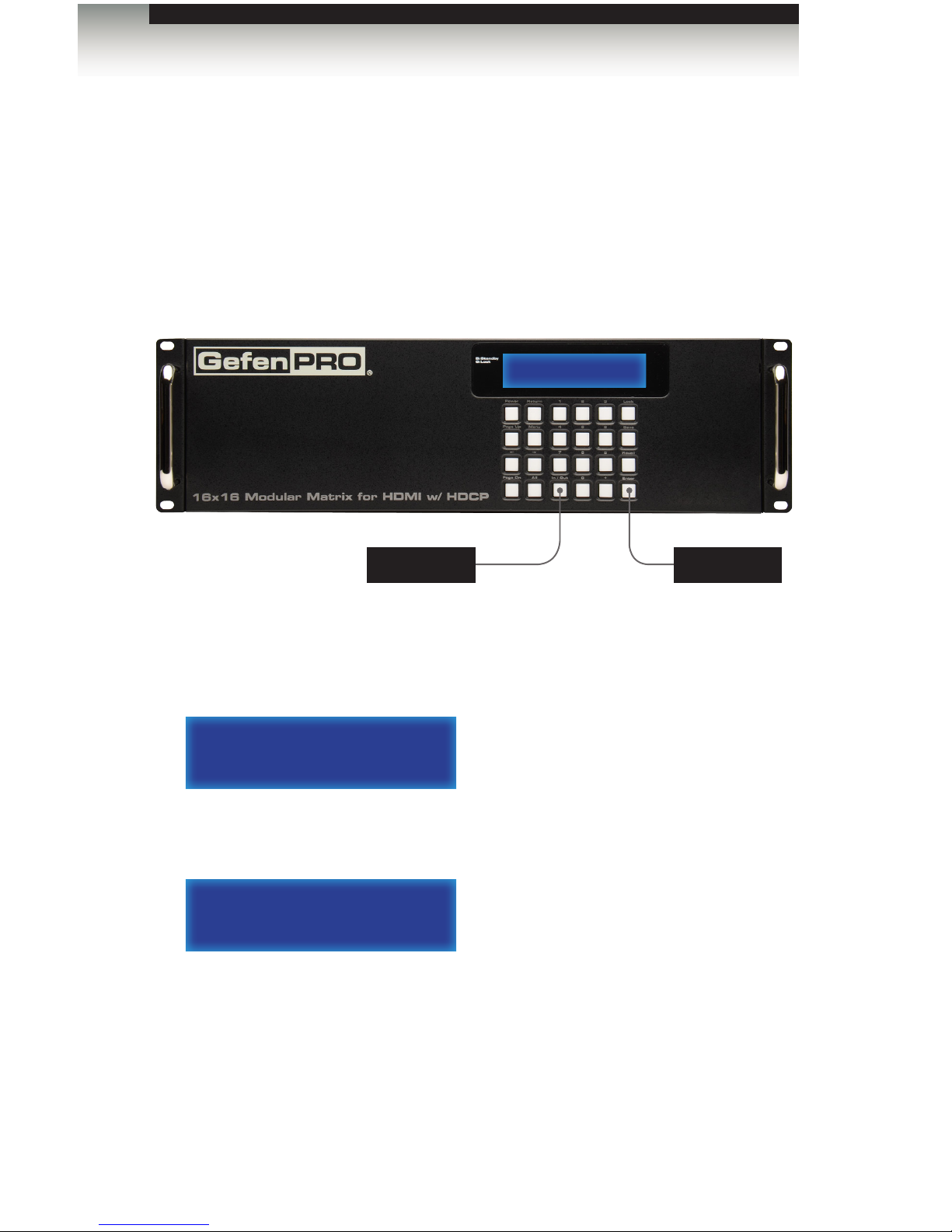
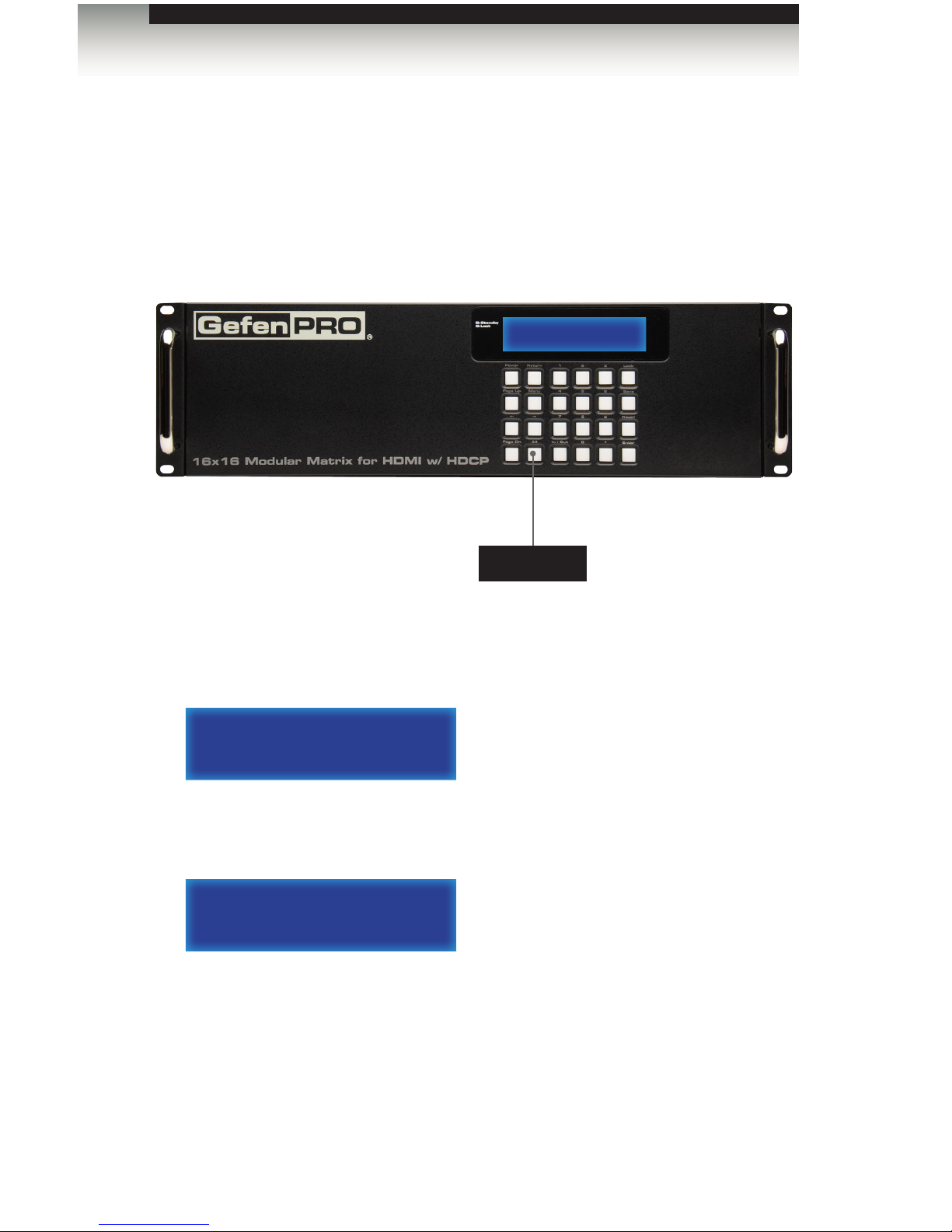
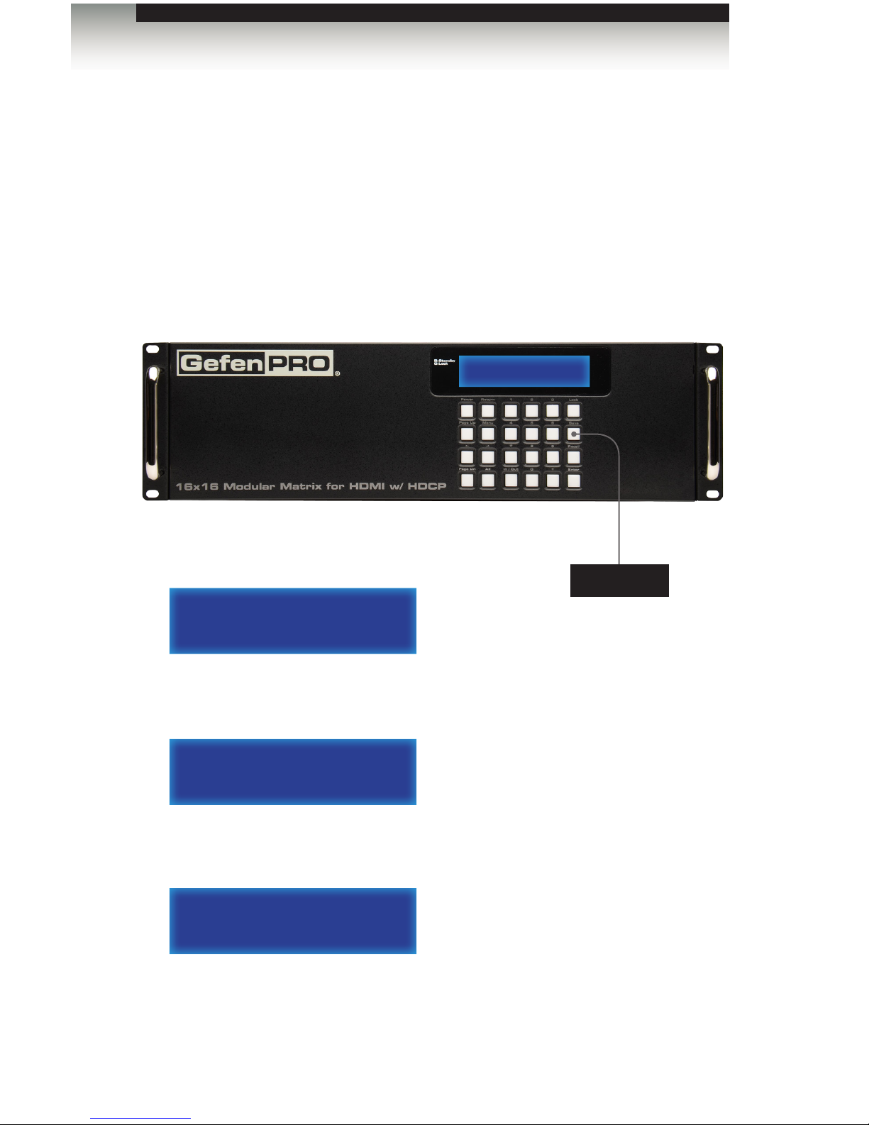
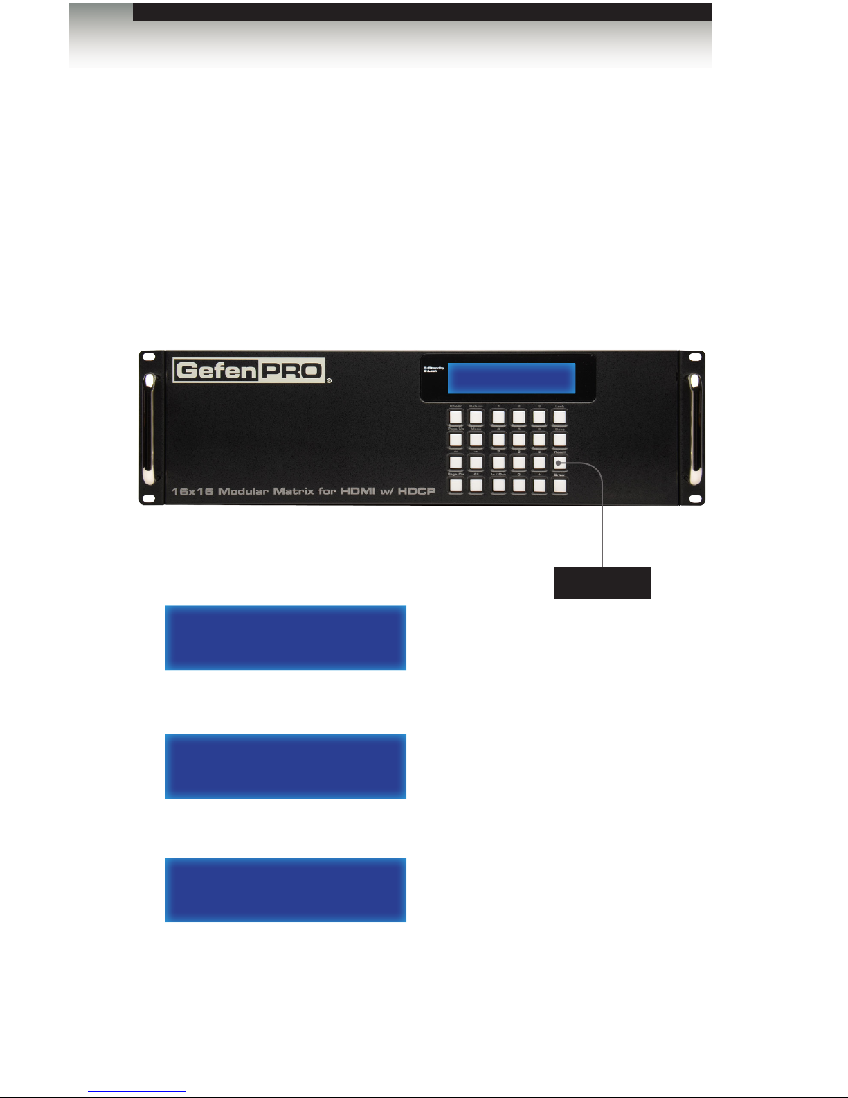
Front Panel
ID Name Description
1 Standby / Lock (LED) When the matrix is in standby mode,
this LED indicator will glow bright blue.
When the matrix is locked, the LED
indicator will glow bright green.
See Locking the Matrix for more
information.
2 IR sensor This IR sensor receives signals from an IR
remote.
3 Front panel display Provides feedback and matrix status during
various operations.
4 Front panel buttons Used to control various features on the
Matrix. See the section Basic Operation for
more information.
GEFEN
16x16 MATRIX
Getting Started
Panel Layout
3
42
1
Page 14

page | 4
Back Panel
(GEF-HDFST-MOD-16416-HDELR shown)
ID Name Description
1 Grounding terminal Connect a grounding wire from the grounding
terminal to an approved ground path.
2 Output (1 - 16) These two expansion bays accept Output
cards, only (HDMI or ELR).
3 Input (1 - 16) These two expansion bays accept Input
cards, only (HDMI).
4 IR Ext Connect an IR Extender (Gefen part no.
EXT-RMT-EXTIRN) to this port.
5 RS-232 Connect the included RS-232 cable from this
port to an RS-232 device. See RS-232 and
IP Conguration for more information.
6 IP Control Connect an Ethernet cable between
this jack and a LAN to use IP control.
See RS-232 and IP Conguration for more
information.
Getting Started
Panel Layout
6 7 9 10 11542
8 1131
Page 15

page | 5
Getting Started
Panel Layout
7 IR All (Out) Connect an IR blaster to this port to send
IR commands to multiple devices.
This port is only active if the unit is
congured with the ELR-POL Output
option.
8 IR All (In) This port is designed to be used with an
IP-based automation control device.
Connect the IR cable from an IR Emitter
port on the automation control device to
this IR port. This port is only active if the
unit is congured with the ELR-POL Output
option.
9 USB This mini USB port is used for upgrading
the rmware. See Upgrading using USB
for more information.
10 HDMI Local Out Connect a local HDTV display to this HDMI
port. This port is useful for monitoring the
currently routed input signal.
11 IEC connector Connect the included AC power cords
from these power receptacles to available
electrical outlets.
Page 16

page | 6
The IR remote control unit (Gefen part no. RMT-MOD-IRN) is not included 16x16 Modular
Matrix for HDMI with HDCP but can be purchased separately.
Front
ID Name Description
1 Activity indicator This LED ashes bright orange when a key
is pressed on the remote.
2 Input Selection (0 - 9) Press these buttons to switch to the
desired input (source).
3 Enter Press this button to commit the routing
change.
IR Remote Control Unit
NOTE: An Activity indicator that ashes quickly while holding down
any one of the buttons indicates a low battery. Replace the battery
as soon as possible. See Installing the Battery.
Getting Started
1
4
6
2
3
5
7
Page 17

page | 7
ID Name Description
4 Input Press this button prior to selecting the
input.
5 Output Press this button prior to selecting the
output.
6 Recall Press this button prior to entering the
preset to be loaded.
7 Save When saving a routing state, press this
button prior to entering the preset number.
Getting Started
IR Remote Control Unit
Page 18

page | 8
Back
(shown with cover removed)
ID Name Description
1 DIP switch bank Use these DIP switches to set the IR
channel of the remote. See Setting the IR
Channel for more information.
2 Primary battery slot
(shown without battery)
Holds the battery for operating the remote.
Use only 3V CR2032-type batteries.
Make sure that the positive (+) side of the
battery is facing up.
3 Alternate battery slot Allows for the installation of secondary
(backup) battery.
2
1
3
Getting Started
IR Remote Control Unit
Page 19

page | 9
Installing the Battery
The IR remote control unit ships with two batteries. Only one battery is required for
operation. The second battery is a spare.
1. Remove the back cover the IR Remote Control unit.
2. Insert the included battery into the primary battery slot. The positive (+) side of the
battery should be facing up.
3. Replace the back cover.
Setting the IR Channel
In order for the included IR remote control to communicate with the 16x16 Modular Matrix
for HDMI with HDCP, the IR remote control must be set to the same channel as the matrix.
Use the #set_ir command to set the IR channel of the matrix.
IR Channel DIP settings
0
(default)
1 2
ON
1
1 2
ON
1 2
2
1 2
ON
3
1 2
ON
IR Remote Control Unit
WARNING: Use only 3V CR2032-type batteries. Risk of explosion
if battery is replaced by an incorrect type. Dispose of used batteries
according to the instructions.
DIP switches
Getting Started
Page 20

Page Title
As there are several versions of the 16x16 Modular Matrix for HDMI w/HDCP available,
each version will be covered. Locate the connection instructions for the version which was
purchased. The wiring diagram at the bottom of the page provides a general reference for
connecting the 16x16 Modular Matrix for HDMI w/ HDCP.
► GEF-HDFST-MOD-16416-HD
► GEF-HDFST-MOD-16416-HDELR
Sample Wiring Diagram
WARNING: Both power supplies should always be connected
to grounded electrical AC outlets. Each power cord should be
connected to an electrical outlet on a separate circuit.
page | 10
Getting Started
Installation
GEF-HDFST-MOD-16416
Total HDMI Output Combinations
16x16 Modular Matrix
for HDMI with HDCP
HDMI Sources
®
Up to
16x
IR Emitters**
Up to
16x
IR Emitters**
Up to
16x
IR Extenders**
Up to
16x
Up to
16x
GEF-HD-2IR-ELRPOL-R
Local Monitor
Receivers
** Dependant on the number of ELR-POL Sender boards in the matrix
VIDEO GAME MODE
Playing: SCALER WARS
LEVEL: 22
VIDEO GAME MODE
Playing: SCALER WARS
LEVEL: 22
IP Control
Network
HDMI CABLE
RS-232 CABLE
CAT-5 CABLE
IR
IP-based
Automation Control Device
Page 21

GEF-HDFST-MOD-16416-HD
1. Connect up to 16 Hi-Def sources to the HDMI inputs on the rear panel of the 16x16
Modular Matrix for HDMI w/ HDCP using HDMI cables.
2. Connect up to 16 HDTV displays to the HDMI outputs on the rear panel of the 16x16
Modular Matrix for HDMI w/ HDCP.
3. Connect both AC power cords from the 16x16 Modular Matrix for HDMI w/ HDCP to
available electrical outlets. Connecting both AC power cords will provide redundancy
should one of the power supplies fail. It is recommended that each power cord be
connected to an electrical outlet on a separate circuit.
GEF-HDFST-MOD-16416-HDELR
1. Connect up to 16 Hi-Def sources to the HDMI inputs on the rear panel of the 16x16
Modular Matrix w/ HDCP using HDMI cables.
2. Connect a CAT-5e cable (or better), up to 330 feet (100 meters) from each ELR-POL
jack on the Sender card to each of the included ELR-POL Receiver units, as shown
below.
Once the matrix is powered, the Link indicators will glow bright green to indicate a
solid link between the output card and the Receiver unit.
The POL indicators will glow bright amber to indicate that the Receiver unit is being
powered.
(continued on next page)
page | 11
Getting Started
Installation
CAT-5e cable
Up to 330 feet (100 meters)
GEF-HD-2IR-ELRPOL-R
Page 22

page | 12
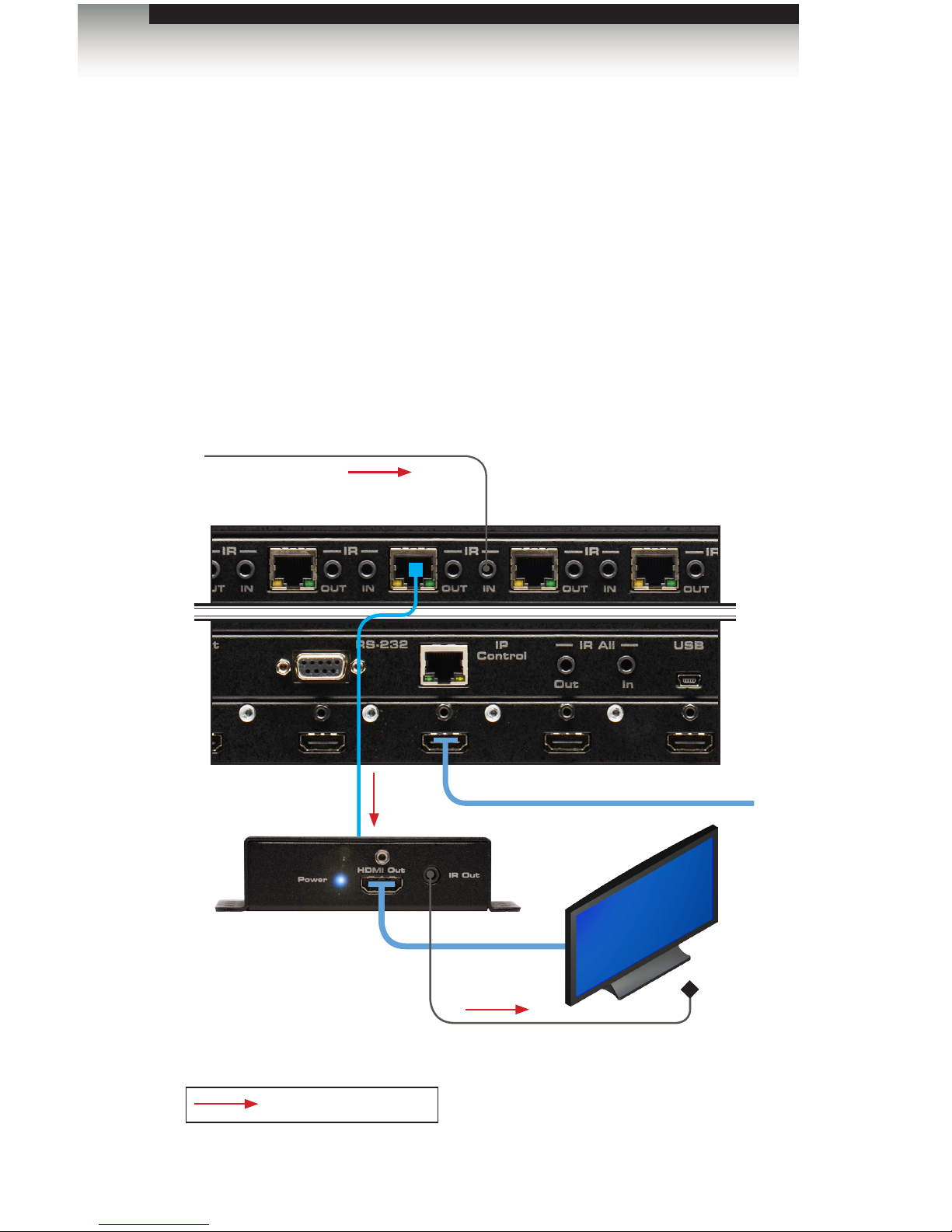
3. Connect an HDMI cable from the HDMI Out port on each ELR-POL Receiver unit to
an HDTV display.
4. Connect both AC power cords from the 16x16 Modular Matrix for HDMI w/ HDCP to
available electrical outlets. Connecting both AC power cords will provide redundancy
should one of the power supplies fail. It is recommended to connect each power cord
to electrical outlets on two separate circuits.
Power to the Receiver unit is delivered from the power supply in the matrix over the
CAT-5e cable using Gefen Power Over Line (POL) technology. The Link indicator will
glow bright green to indicate a solid connection between the matrix and the Receiver
unit. The Power indicator will glow bright blue to indicate that the Receiver unit is
being powered.
If either of these LED indicators are OFF, inspect the CAT-5 cable for loose
connections or possible defects.
Getting Started
Installation
HDMI cable
HDTV display
GEF-HD-2IR-ELRPOL-R
Page 23

Page 24

Page 25

02 Operating the
16x16 Modular Matrix
for HDMI w/ HDCP
16x16
Modular Matrix for
HDMI with HDCP
sources displays
Basic Operation ................................................................................................... 16
Standby Mode ............................................................................................. 16
Powering the Matrix .................................................................................... 16
Accessing the Menu System ....................................................................... 17
Menu System ...................................................................................................... 19
IP Conguration Menu ................................................................................ 19
Temperature Menu ...................................................................................... 21
LCM Contrast Menu .................................................................................... 22
Routing Basics .................................................................................................... 23
Displaying the Current Routing Status ........................................................ 23
Routing a Source to an Output .................................................................... 24
Routing a Source to Multiple Outputs ......................................................... 28
Routing a Source to All Outputs .................................................................. 30
Saving a Routing Preset ............................................................................. 32
Recalling a Saved Routing Preset .............................................................. 34
Locking the Matrix ............................................................................................... 36
Using Bidirectional IR .......................................................................................... 37
Controlling the Display from the Source Location ....................................... 37
Controlling the Source from the Viewing Location ...................................... 38
Controlling Multiple Sources ....................................................................... 39
Controlling the Matrix from the Viewing Location ........................................ 40
Page 26

page | 16
Standby Mode
After the AC power cord(s) is/are connected to the matrix, the LED indicator next to the
display will glow bright blue. The matrix is now in standby mode.
Standby mode is similar to powering-off the matrix. However, in standby mode, the matrix
can be powered-on by executing the #power command. See RS-232 and IP Conguration
for more information on using the RS-232 / IP commands.
Powering the Matrix
1. From standby mode, press the Power button on the front panel.
2. The standby mode LED will turn off.
3. After a few moments, the home screen will be displayed:
4. To return to standby mode, press the Power button on the front panel.
Operating the 16x16 Modular Matrix for HDMI w/ HDCP
Basic Operation
GEFEN
16x16 matrix
Standby mode LED Power
Page 27

page | 17
Accessing the Menu System
The 16x16 Modular Matrix for HDMI w/ HDCP uses a built-in menu system which provides
access to other non-routing functions. Use the Menu button to access the menu system.
1. From the home screen, press the Menu button.
2. To cycle through each of the menus, do one of the following:
► Consecutively press the Menu button. Using the Menu button will move forward
through each of the menus.
► Use the Page Up or Page Dn buttons. Use the Page Up button to go backward
through each menu system. Use the Page Dn button to go forward through the
menu system.
3. Press the Return button at any time to return to the home screen.
(continued on next page)
GEFEN
16x16 MATRIX
GEFEN
16x16 matrix
Operating the 16x16 Modular Matrix for HDMI w/ HDCP
Basic Operation
Return
Menu
Page Up
Page Dn
Page 28

page | 18
Operating the 16x16 Modular Matrix for HDMI w/ HDCP
Basic Operation
Display Description
1. IP CONFIG
Allows IP conguration for the following: IP
address, Net mask, and Gateway address.
See RS-232 and IP Conguration for more
information.
2. temperature
Provides temperature information of the internal
boards. See Temperature Menu for more
information.
3. LCM contrast
Allows contrast adjustment of the front-panel
display. See LCM Contrast Menu for more
information.
Page 29

page | 19
IP Conguration Menu
The 16x16 Modular Matrix for HDMI w/ HDCP can be controlled using the built-in Web
interface, Telnet, or UDP protocols. In order to use these communication methods, the IP
settings of the matrix must be set accordingly. The IP Conguration menu displays
the current IP address, net mask, and gateway address for the matrix.
1. From the home screen, press the Menu button. The IP Cong menu will be
displayed.
2. Press the Enter button to enter the IP Cong menu. The current IP address of
the matrix will be displayed.
GEFEN
16x16 MATRIX
Operating the 16x16 Modular Matrix for HDMI w/ HDCP
Menu System
NOTE: Depending upon the network, all related IP, Telnet, and UDP
settings will need to be assigned. IP settings cannot be changed
using the front-panel buttons and must be congured using the
RS-232 / IP command set. See RS-232 and IP Conguration for
more information.
1. IP CONFIG
1a. IP address:
192.168.1.239
Enter
Menu
Page 30

page | 20
3. Press the ← or → button to move backward or forward, respectively, to display
the current IP address, net mask, and gateway address of the matrix.
Display Description
1a. IP address:
192.168.1.239
Displays the current IP address of the matrix.
Use the #sipadd command to change the IP
address.
1B. NETMASK
255.255.255.0
Displays the subnet mask of the matrix.
Use the #snetmask command to change the
subnet mask.
1C. GATEWAY
192.168.1.1
Displays the gateway address of the matrix.
Use the #sgateway command to change the
gateway address.
4. Press the Return button, twice, to return to the home screen.
1a. ip address:
192.168.1.239
Operating the 16x16 Modular Matrix for HDMI w/ HDCP
A
A
Menu System
Return
Page 31

page | 21
Menu System
Operating the 16x16 Modular Matrix for HDMI w/ HDCP
Temperature Menu
Temperature data within the enclosure can be reported using the buttons on the front panel.
1. From the home screen, press the Menu button. The IP Cong menu will be
displayed.
2. Consecutively press the Page Up or Page Dn button until the Temperature menu
is displayed.
3. Press the Enter button to enter the Temperature menu. The temperature for each
of the internal boards will be displayed.
4. Press the Return button, twice, to return to the home screen.
1. IP CONFIG
2. temperature
GEFEN
16x16 matrix
2a. t1: 44.375 C
T2: 43.250 C
°
°
Page 32

page | 22
Menu System
Operating the 16x16 Modular Matrix for HDMI w/ HDCP
LCM Contrast Menu
The LCM Contrast Menu is used to adjust the visual intensity (contrast) of the characters
in the front-panel display. The contrast can be set to four different levels of intensity.
The default value is 4.
1. From the home screen, press the Menu button. The IP Cong menu will be
displayed.
2. Consecutively press the Page Up or Page Dn button until the LCM Contrast menu
is displayed.
3. Press the Enter button to enter the LCM Contrast menu.
4. Enter a number between 1 and 4, using the keypad on the front panel. For example,
to set the contrast to 1, press button 1 on front panel. Once the desired button is
pressed, the value will appear in the display and the setting will take effect. If another
setting is desired, enter a number between 1 and 4 to see the effect.
5. Press the Enter button to accept the changes. The display will indicate “OK”.
6. After a few moments, the home screen will be displayed.
1. IP CONFIG
3. LCM CONTRAST
3a. contrast:
range: 1-4
3a. contrast: 1
range: 1-4
3a. contrast: 1
range: 1-4 OK
Page 33

page | 23
Operating the 16x16 Modular Matrix for HDMI w/ HDCP
Routing Basics
Displaying the Current Routing Status
To display the current routing status of the 16x16 Modular Matrix for HDMI w/ HDCP, press
the Page Up or Page Dn buttons.
1. Press the Page Dn button on the front panel. The routing status of the rst four
outputs is displayed.
In the illustration below, we can see that Input 1 is routed to Output 1, Input 7 is routed
to Output 2, and so on.
2. Press the Page Dn button to view the routing status of the next four inputs / outputs.
Consecutively press the Page Dn button to view the next four outputs. The last item
to be displayed will be the routing status of HDMI Local Out.
out: 5 6 7 8
IN: 10 4 4 7
out:17 - local
in: 3
Out: 1 2 3 4
IN: 1 7 2 1
Page Up
Page Dn
Page 34
page | 24
Operating the 16x16 Modular Matrix for HDMI w/ HDCP
Routing a Source to an Output
Using the Front Panel Buttons
The following example illustrates how to route a source to an output. An input may be
routed to a single or multiple outputs. Multiple inputs cannot be routed to a single output.
1. Press the In / Out button on the front panel.
2. The front panel display will indicate that routing mode is active.
3. Select an input (1 - 16) using the numerical keys on the front panel. For this example,
we will route Input 15 to Output 12. Enter the input by pressing buttons 1 and 5.
If an incorrect value is entered by accident, use the ← button to delete the last
number entered.
port select
IN:
port select
IN: 15
port select
IN:
In / Out Enter
Routing Basics
Page 35

page | 25
Operating the 16x16 Modular Matrix for HDMI w/ HDCP
4. Press the In / Out button, again. The display will change to the following:
5. Enter the number of the output using the numerical keys on the front panel. Since
we want to route Input 15 to Output 12, we will press buttons 1 and 2. The selected
output will appear on the display.
Once again, if an incorrect output value is entered by accident, use the ← button to
delete the last number entered.
If the decision to change the input is made, press the Return button to go back to the
previous screen. The previous input entry will automatically be erased:
6. Once the desired input and output have been entered, press the Enter button to
execute the routing process. The display will show the following:
7. After a few moments, the home screen will be displayed.
OUT:
IN: 15
Routing Basics
OUT: 12
IN: 15
port select
IN:
OK
GEFEN
16x16 matrix
Page 36

page | 26
Operating the 16x16 Modular Matrix for HDMI w/ HDCP
Using the IR Remote Control
1. Press the Input button on the IR remote control.
2. The front panel display will indicate that routing mode is active.
3. Select an input (1 - 16) using the numerical keys on the IR remote control. For this
example, we will route Input 7 to Output 12. Enter the input by pressing button 7.
If an incorrect value is entered by accident, press the Return button.
4. Press the Output button.
port select
IN:
port select
IN: 7
Routing Basics
Page 37

page | 27
Operating the 16x16 Modular Matrix for HDMI w/ HDCP
The display will change to the following:
5. Enter the number of the output using the numerical keys on the IR remote control.
Since we want to route Input 7 to Output 12, we will press buttons 1 and 2.
The selected output will appear on the display.
If an incorrect output value is entered by accident, press the Return button to restart
the routing process. Pressing the Return button will return the matrix to the home
screen.
6. Once the desired input and output have been entered, press the Enter button to
execute the routing process.
7. After a few moments, the home screen will be displayed.
OUT:
IN: 7
Routing Basics
OUT: 12
IN: 7
GEFEN
16x16 matrix
GEFEN
16x16 matrix
Page 38

page | 28
Operating the 16x16 Modular Matrix for HDMI w/ HDCP
Routing Basics
Routing a Source to Multiple Outputs
The following example illustrates how to route a source to multiple outputs.
1. Press the In / Out button on the front panel.
2. The front panel display will indicate that routing mode is active.
3. Select an input (1 - 16) using the numerical keys on the front panel.
If an incorrect value is entered by accident, use the ← button to delete the last
number entered.
port select
IN:
port select
IN: 3
port select
IN:
+
IMPORTANT: When routing a source to multiple outputs, HDMI
Local Out (Output 17) is not included as part of the routing process.
To route a source to HDMI Local Out, it must be performed
separately. See Routing a Source to an Output or Routing a Source
to Multiple Outputs.
Page 39

page | 29
4. Press the In / Out button, again. The display will change to the following:
5. Enter the number of the rst output using the numerical keys on the front panel.
The selected output will appear on the display.
If an incorrect output value is entered by accident, use the ← button to delete the last
number entered.
If the decision to change the input is made, press the Return button to go back to the
previous screen. The previous input entry will automatically be erased:
6. Press the + button to add another output.
7. Enter the desired output. In the example below, we have entered 4.
8. Repeat steps 6 and 7 to add more outputs.
9. Press the Enter button to complete the routing procedure.
10. After a few moments, the home screen will be displayed.
Operating the 16x16 Modular Matrix for HDMI w/ HDCP
Routing Basics
OUT:
IN: 3
OUT: 12
IN: 3
OUT: 12
IN: 3 3
OUT: 12 4
IN: 3 3
GEFEN
16x16 matrix
Page 40
page | 30
Operating the 16x16 Modular Matrix for HDMI w/ HDCP
Routing Basics
Routing a Source to All Outputs
The following example illustrates the process for routing a single input to all outputs,
simultaneously.
1. Press the All button on the front panel.
2. The display on the front panel will show the following:
3. Select an input (1 - 16) using the numerical keys on the front panel. For this example,
we will route Input 10 to all outputs. Therefore, we’ll press buttons 1 and 0.
If an incorrect value is entered by accident, use the ← button to delete the last
number entered.
Switch all out
TO :
Switch all out
TO : 10
switch all out
to :
All
Page 41

page | 31
Operating the 16x16 Modular Matrix for HDMI w/ HDCP
Routing Basics
4. Press the Enter button on the front panel.
5. The display will indicate that the routing process was successful.
6. After a few moments, the home screen will be displayed.
Switch all out
TO : 10 OK
GEFEN
16x16 matrix
Page 42
page | 32
Saving a Routing Preset
Using the Front Panel Buttons
The 16x16 Modular Matrix for HDMI w/ HDCP allows routing (and masking) states to be
saved to internal non-volatile memory. Each routing state can be recalled at a later time.
Even if the matrix is powered OFF, the presets will be retained in memory.
1. Press the Save button on the front panel.
2. The display will show the following:
3. Select a preset (1 - 8) by using the numerical keys on the front panel. For this
example, we will save the current routing status to Preset 2 by pressing button 2.
4. Press the Enter button to save the current routing state to the preset. The front-panel
display will indicate that the preset has been saved.
5. After a few moments, the home screen will be displayed.
GEFEN
16x16 MATRIX
Routing Basics
Operating the 16x16 Modular Matrix for HDMI w/ HDCP
save to
no: (1-8)
save to
no: 2 (1-8)
save to
no: 2 OK (1-8)
Save
Page 43

page | 33
Using the IR Remote Control
1. Press the Save button on the IR remote control.
2. The display will show the following:
3. Select a preset (1 - 8) by using the numerical keys on the IR remote control.
For this example, we will save the current routing status to Preset 3 by pressing
button 3.
If an incorrect output value is entered by accident, press the Return button to restart
the process. Pressing the Return button will return the matrix to the home screen.
4. Press the Enter button to save the current routing state to the preset. The front-panel
display will indicate that the preset has been saved.
5. After a few moments, the home screen will be displayed.
Routing Basics
Operating the 16x16 Modular Matrix for HDMI w/ HDCP
save to
no: (1-8)
save to
no: 3 (1-8)
save to
no: 3 OK (1-8)
Page 44
page | 34
Recalling a Saved Routing Preset
Using the Front Panel Buttons
The 16x16 Modular Matrix for HDMI w/ HDCP allows saved routing (and masking) states
to be recalled from memory for instant access.
In this example, we will recall the routing preset that we stored in the previous example.
1. Press the Recall button on the front panel.
2. The display will show the following:
3. Select a preset (1 - 8) by using the numerical keys on the front panel. For this
example, we will recall Preset 3 by pressing button 3.
4. Press the Enter button to recall the preset.
5. After a few moments, the home screen will be displayed.
GEFEN
16x16 MATRIX
Routing Basics
Operating the 16x16 Modular Matrix for HDMI w/ HDCP
recall from
no: (1-8)
recall from
no: 3 (1-8)
recall from
no: 3 OK (1-8)
Recall
Page 45

page | 35
Using the IR Remote Control
1. Press the Recall button on the IR remote control.
2. The display will show the following:
3. Select a preset (1 - 8) by using the numerical keys on the front panel. For this
example, we will recall Preset 3 by pressing button 3.
If an incorrect output value is entered by accident, press the Return button to restart
the process. Pressing the Return button will return the matrix to the home screen.
4. Press the Enter button to recall the preset. The front-panel display will indicate that
the preset has been loaded.
5. After a few moments, the home screen will be displayed.
Routing Basics
Operating the 16x16 Modular Matrix for HDMI w/ HDCP
recall from
no: (1-8)
recall from
no: 3 (1-8)
save to
no: 2 OK (1-8)
Page 46

GEFEN
16x16 MATRIX
page | 36
Locking the matrix will prevent any changes by disabling all buttons (except the Lock
button) on the front panel. This feature is useful in preventing routing or other changes
caused by accidentally bumping or pressing the buttons on the front panel.
1. Press the Lock button on the front panel.
2. Once the matrix is locked, the LED indicator next to the display will glow bright green.
3. To unlock the matrix, press and hold the Lock button again, until the LED indicator
turns off. The display will return to the home screen.
Operating the 16x16 Modular Matrix for HDMI w/ HDCP
Lock
Locking the Matrix
keypad locked
GEFEN
16x16 matrix
Page 47
The 16x16 Modular Matrix for HDMI w/ HDCP provides IR control. Use an IR extender
(Gefen part no. EXT-RMT-EXTIRN) to control the source device from the viewing location
or an automation system to control the display (or other sink device). Refer to the user
documentation that came with your automation system for details.
Controlling the Display from the Source Location
1. Connect the 3.5mm mini-mono end of the IR cable from the IR IN port on the matrix to the
automation system.
2. Connect an IR emitter (Gefen part no. EXT-IREMIT) from the IR Out jack on the Receiver
unit to IR sensor on the display.
page | 37
Operating the 16x16 Modular Matrix for HDMI w/ HDCP
IR Control
HDMI cable
HDMI cable
Receiver unit
Matrix
CAT-5
To source
IR emitter
from Automation
System
IR signals
Page 48

Controlling the Source from the Viewing Location
1. Connect an IR extender (Gefen part no. EXT-RMT-EXTIRN) to the IR Ext port on the
Receiver unit.
2. Connect an IR emitter (Gefen part no. EXT-IREMIT) from the IR OUT jack on the 16x16
Modular Matrix for HDMI w/ HDCP to the IR sensor on the source device.
page | 38
Operating the 16x16 Modular Matrix for HDMI w/ HDCP
IR Control
IR signals
IR emitter
HDMI cable
Receiver unit
Matrix
Source
IR extender
CAT-5e cable (or better)
up to 330 feet (100 meters)
Page 49

page | 39
Controlling Multiple Sources
1. Connect an IR extender (Gefen part no. EXT-RMT-EXTIRN) to the IR Ext port on the
Receiver unit.
2. Connect an IR emitter (Gefen part no. EXT-IREMIT) to the IR OUT jack on the 16x16
Modular Matrix for HDMI w/ HDCP.
3. Another IR emitter can be connected to the IR All Out port, in order to control individual
(or multiple) sources that are not controlled using the IR emiiter connected to the IR OUT
port.
Operating the 16x16 Modular Matrix for HDMI w/ HDCP
IR Control
IR signals
CAT-5
IR extender
IR emitter
IR emitter
Source
Receiver unit
Page 50
page | 40
Operating the 16x16 Modular Matrix for HDMI w/ HDCP
IR Control
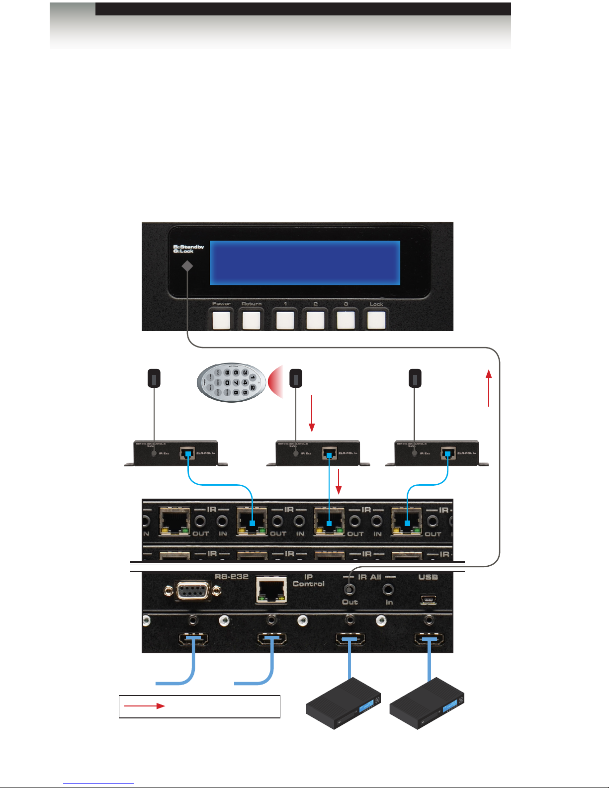
Controlling the Matrix from the Viewing Location
Routing can be managed from any viewing location, using the included IR remote control unit,
regardless of the current routing state of the matrix.
1. Connect an IR extender (Gefen part no. EXT-RMT-EXTIRN) to the IR Ext jack on each
Receiver unit.
2. Connect an IR emitter (Gefen part no. EXT-IREMIT) from the IR All Out port on the back
of the matrix and place the emitter over the IR sensor on the front panel of the matrix.
Front of MatrixBack of Matrix
port select
IN:
RMT-MOD-IRN remote
IR emitter
IR extender
IR signals
Page 51

Page 52

Page 53

03 Advanced Operation
16x16
Modular Matrix for
HDMI with HDCP
sources displays
RS-232 and IP Conguration .............................................................................. 44
RS-232 Interface ......................................................................................... 44
RS-232 Settings .......................................................................................... 44
IP / UDP Conguration ................................................................................ 45
Commands .......................................................................................................... 46
IP Conguration .......................................................................................... 46
UDP Conguration ...................................................................................... 57
FST ............................................................................................................. 61
Routing and Masking .................................................................................. 64
System ........................................................................................................ 74
Web Interface ...................................................................................................... 94
Using the built-in Web Server ..................................................................... 94
Main ► Routing .......................................................................................... 95
Main ► I/O Status ..................................................................................... 101
Main ► Display Info .................................................................................. 103
I/O Setup ► Preset Names ....................................................................... 104
I/O Setup ► I/O Names ............................................................................ 105
I/O Setup ► HPD Control ......................................................................... 106
I/O Setup ► FST ....................................................................................... 107
I/O Setup ► HDCP ................................................................................... 108
Manage EDID ► Assign ........................................................................... 109
Manage EDID ► Bank Names ................................................................. 112
Manage EDID ► Upload/Download .......................................................... 113
Conguration ► Change IP Settings ........................................................ 114
Page 54
page | 44
Advanced Operation
RS-232 and IP Conguration
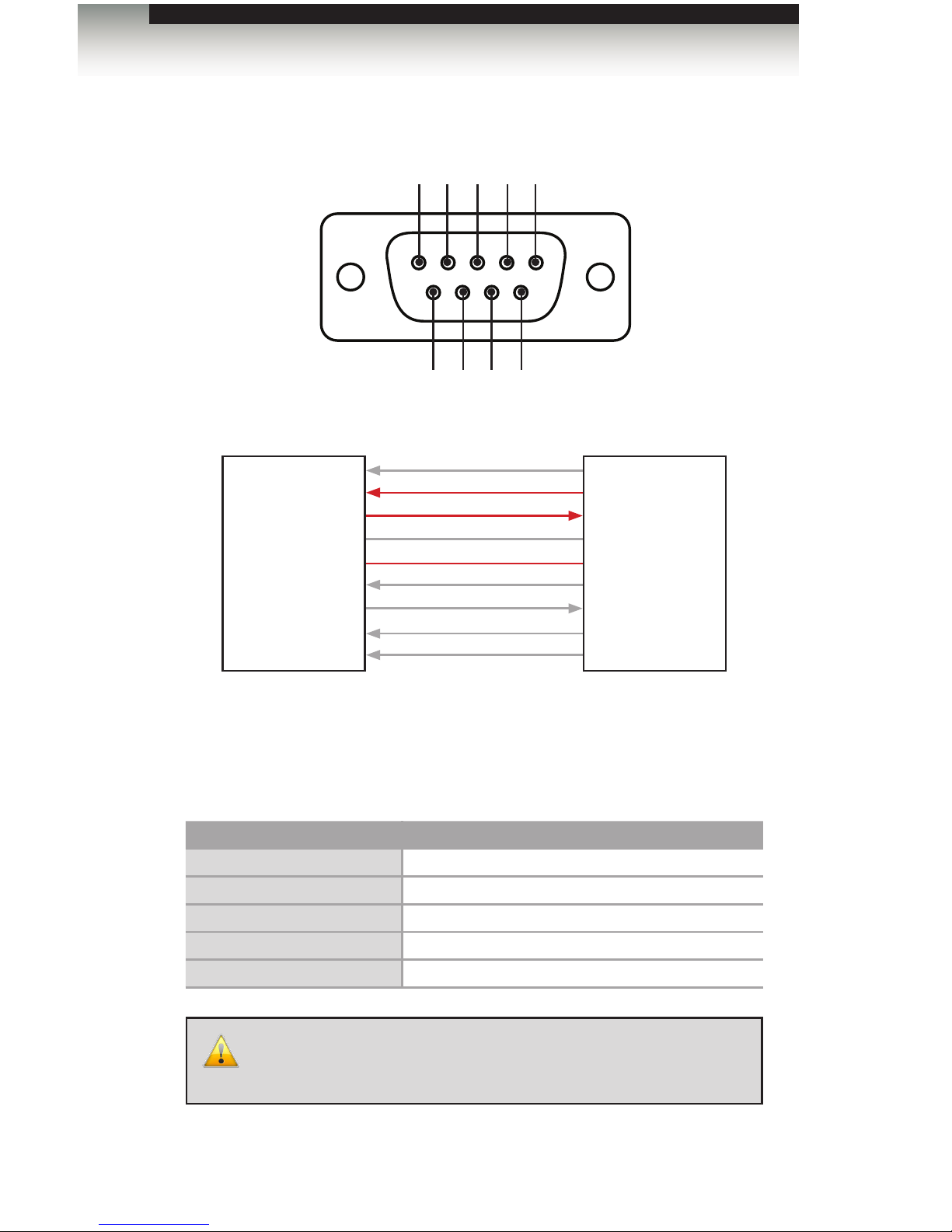
RS-232 Interface
Only TXD, RXD, and GND pins are used.
RS-232 Settings
Description Setting
Baud rate
19200
Data bits
8
Parity
None
Stop bits
1
Hardware ow control
None
IMPORTANT: When sending RS-232 commands, a carriage return
must be included at the end of the command. A space must be
included between the command and the parameter.
DE-9
564738291
DCD
RXD
TXD
DTR
GND
DSR
RTS
CTS
R1
DCD
RXD
TXD
DTR
GND
DSR
RTS
CTS
R1
1
2
3
4
5
6
7
8
9
1
2
3
4
5
6
7
8
9
RS-232 Controller Matrix
Page 55

page | 45
Advanced Operation
RS-232 and IP Conguration
IP / UDP Conguration
The 16x16 Modular Matrix for HDMI w/ HDCP supports IP-based control using Telnet, UDP,
or the built-in Web-based GUI. To set up IP control, the network settings for the 16x16
Modular Matrix for HDMI w/ HDCP must be congured via RS-232. The default network
settings for the matrix are as follows:
Description IP Address / Port Description IP Address / Port
IP Address
192.168.1.72
UDP Port
23
Subnet
255.255.255.0
Local UDP Port
50007
Gateway
192.168.1.1
Remote UDP IP
192.168.1.255
HTTP Port
80
Remote UDP Port
50008
1. Connect an RS-232 cable from the PC to the 16x16 Modular Matrix for HDMI w/
HDCP. Also make sure that an Ethernet cable is connected between the matrix and
the network.
2. Launch a terminal emulation program (e.g. HyperTerminal) and use the RS-232
settings listed on the previous page.
3. Set the IP address for the matrix using the #sipadd command.
4. Set the subnet mask using the #snetmask command.
5. Set the gateway (router) IP address using the #sgateway command.
6. Set the Telnet listening port using the #set_telnet_port command.
7. Set the HTTP listening port using the #set_http_port command.
8. Set the UDP remote IP address for the matrix using the #set_udp_remote_ip
command.
9. Set the UDP listening port for the matrix using the #set_udp_port command.
10. Set the UDP remote port for the matrix using the #set_udp_remote_port
command.
11. Reboot the matrix to apply all changes, then type the IP address that was specied in
step 3, in a Web browser to access the Web GUI. Use the same IP address to Telnet
to the matrix.
NOTE: Depending upon the network, all related IP, Telnet, and
UDP settings will need to be assigned. Consult your network
administrator to obtain the proper settings.
Page 56

page | 46
Advanced Operation
IP Conguration
Command Description
#display_telnet_welcome
Enable / disable the Telnet welcome message
#ipcong
Displays the current IP conguration
#resetip
Resets the IP conguration to factory-default settings
#set_http_port
Sets the Web server listening port
#set_telnet_pass
Sets the Telnet password
#set_telnet_port
Sets the Telnet listening port for the matrix
#set_webui_ad_pass
Sets the Administrator password for the Web GUI
#set_webui_op_pass
Sets the Operator password for the Web GUI
#sgateway
Sets the IP address of the (router) gateway
#show_gateway
Displays the current gateway address of the matrix
#show_http_port
Displays the current HTTP listening port of the matrix
#show_ip
Displays the current IP address of the matrix
#show_mac_addr
Displays the MAC address of the matrix
#show_netmask
Displays the current net mask of the matrix
#show_telnet_port
Displays the Telnet listening port
#sipadd
Sets the IP address of the matrix
#snetmask
Sets the Net mask of the matrix
#use_telnet_pass
Force password during Telnet sessions
Commands
Page 57

page | 47
Commands
Advanced Operation
#display_telnet_welcome
The #display_telnet_welcome command enables / disables the Telnet welcome
message during a Telnet session.
Syntax:
#display_telnet_welcome
Parameters:
param1 Value [0 ... 1]
Value Description
0
Disable welcome message
1
Enable welcome message
Example:
#display_telnet_welcome 1
TELNET WELCOME SCREEN IS ENABLED
When enabled and a Telnet session has been started, the following will appear:
Welcome to GEF-HDFST-MOD-16416 TELNET
telnet->
Page 58

page | 48
#ipcong
The #ipcong command displays the current TCP settings.
Syntax:
#ipcong
Parameters:
None
Example:
#ipcong
IP Conguration is :
IP: 192.168.2.238
NETMASK: 255.255.255.0
GATEWAY: 192.168.2.1
MAC Address: 00-1c-91-03-00-04
#resetip
The #resetip command resets the IP conguration to factory-default settings. The matrix
must be rebooted after executing this command.
Syntax:
#resetip
Parameters:
None
Syntax:
#resetip
IP CONFIGURATION WAS RESET TO FACTORY DEFAULTS
IP: 192.168.1.72
Netmask: 255.255.255.0
Gateway: 192.168.1.1
Commands
Advanced Operation
Page 59

page | 49
Commands
Advanced Operation
#set_http_port
The #set_http_port command species the Web server listening port. The matrix
must be rebooted after executing this command. The default port setting is 80. Use the
#show_http_port command to display the current HTTP listening port.
Syntax:
#set_http_port param1
Parameters:
param1 Port [1 ... 1024]
Example:
#set_http_port 82
HTTP COMMUNICATION PORT 82 IS SET. PLEASE REBOOT THE UNIT.
#set_telnet_pass
The #set_telnet_pass command sets the Telnet password. The password is
case-sensitive and cannot exceed 8 characters in length. The default password is Admin.
Syntax:
#set_telnet_pass param1
Parameters:
param1 Password
Example:
#set_telnet_pass 3ver3st
TELNET INTERFACE PASSWORD IS SET
Page 60

page | 50
Advanced Operation
RS-232 / IP Commands
#set_telnet_port
The #set_telnet_port command sets the Telnet listening port. The matrix must
be rebooted after executing this command. The default port setting is 23. Use the
#show_telnet_port command to display the current Telnet listening port.
Syntax:
#set_telnet_port param1
Parameters:
param1 Port [1 ... 1024]
Example:
#set_telnet_port 24
TELNET COMMUNCATION PORT 24 IS SET. PLEASE REBOOT THE UNIT.
#set_webui_ad_pass
The #set_webui_ad_pass command sets the Administrator password for the Web GUI.
The password is case-sensitive and cannot exceed 7 characters in length. The default
password is Admin.
Syntax:
#set_webui_ad_pass param1
Parameters:
param1 Password
Example:
#set_webui_ad_pass bossman
WEB UI ADMINISTRATOR PASSWORD IS SET
Page 61

page | 51
Commands
Advanced Operation
#set_webui_op_pass
The #set_webui_ad_pass command sets the Operator password for the Web GUI.
The default password is Admin.
Syntax:
#set_webui_op_pass param1
Parameters:
param1 Password
Example:
#set_webui_op_pass minion
WEB UI OPERATOR PASSWORD IS SET
#sgateway
The #sgateway command sets the gateway address. The gateway must be typed using
dot-decimal notation. The matrix must be rebooted after executing this command.
The default gateway is 192.168.1.1.
Syntax:
#sgateway param1
Parameters:
param1 Gateway
Example:
#sgateway 192.168.1.5
GATEWAY ADDRESS 192.168.1.5 IS SET. PLEASE REBOOT THE UNIT.
Page 62

page | 52
Commands
Advanced Operation
#show_gateway
The #show_gateway command displays the current gateway address of the matrix.
Use the #sgateway command to set the gateway address.
Syntax:
#show_gateway
Parameters:
None
Example:
#show_gateway
GATEWAY ADDRESS IS: 192.168.1.5
#show_http_port
The #show_http_port command displays the current HTTP listening port of the matrix.
Use the #set_http_port command to set the HTTP listening port.
Syntax:
#show_http_port
Parameters:
None
Example:
#show_http_port
HTTP COMMUNICATION PORT IS: 82
Page 63

page | 53
Commands
Advanced Operation
#show_ip
The #show_ip command displays the current IP address of the matrix. Use the #sipadd
command to set the IP address.
Syntax:
#show_ip
Parameters:
None
Example
#show_ip
IP ADDRESS IS: 192.168.1.239
#show_mac_addr
The #show_mac_addr command displays the MAC address of the matrix.
Syntax:
#show_mac_addr
Parameters:
None
Example:
#show_mac_addr
MAC ADDRESS IS: 00-1c-91-03-00-02
Page 64

page | 54
Commands
Advanced Operation
#show_netmask
The #show_netmask command displays the current net mask of the matrix. Use the
#snetmask command to set the net mask.
Syntax:
#show_netmask
Parameters:
None
Example:
#show_netmask
NETMASK ADDRESS IS: 255.255.255.0
#show_telnet_port
The #show_telnet_port command displays the current Telnet port of the matrix. Use
the #set_telnet_port command to set the Telnet listening port.
Syntax:
#set_telnet_port param1
Parameters:
param1 Port [1 ... 65535]
Example:
#set_telnet_port 24
TELNET COMMUNCATION PORT 24 IS SET. PLEASE REBOOT THE UNIT.
Page 65

page | 55
Commands
Advanced Operation
#sipadd
The #sipadd command sets the IP address of the matrix. The IP address must be
entered using dot-decimal notation. The matrix must be rebooted after executing this
command. The default IP address is 192.168.1.72. Use the #show_ip or #ipcong
command to display the current IP address of the matrix.
Syntax:
#sipadd param1
Parameters:
param1 IP address
Example:
#sipadd 192.168.1.239
IP ADDRESS 192.168.1.239 IS SET. PLEASE REBOOT THE UNIT.
#snetmask
The #snetmask command sets the subnet mask. The net mask must be entered using
dot-decimal notation. The matrix must be rebooted after executing this command.
The default net mask is 255.255.255.0. Use the #show_netmask command to display
the current net mask of the matrix.
Syntax:
#snetmask param1
Parameters:
param1 Net mask
Example:
#snetmask 255.255.0.0
NETMASK ADDRESS 255.255.0.0 IS SET. PLEASE REBOOT THE UNIT.
Page 66

page | 56
Commands
Advanced Operation
#use_telnet_pass
The #use_telnet_pass command forces the password credentials for each Telnet
session. The default setting is 0 (disabled).
Syntax:
#use_telnet_pass param1
Parameters:
param1 Value [0 ... 1]
Value Description
0
Disable password
1
Enable password
Example:
#use_telnet_pass 1
TELNET INTERACE PASSWORD IS ENABLED
Page 67

page | 57
Advanced Operation
Commands
UDP Conguration
Command Description
#set_udp_port
Sets the local UDP listening port
#set_udp_remote_ip
Sets the remote UDP IP address
#set_udp_remote_port
Sets the remote UDP listening port
#show_udp_port
Displays the current local UDP listening port
#show_udp_remote_ip
Displays the current remote UDP IP address
#show_udp_remote_port
Displays the current remote UDP listening port
#use_udp_enable
Enables / disables UDP access
#set_udp_port
The #set_udp_port command sets the local UDP server listening port. The default port
setting is 21. The matrix must be rebooted after executing this command. Use the
#show_udp_port command to display the current local UDP listening port.
Syntax:
#set_udp_port param1
Parameters:
param1 Port [1 ... 65535]
Example:
#set_udp_port 56
UDP COMMUNICATION PORT 56 IS SET
Page 68

page | 58
Advanced Operation
Commands
#set_udp_remote_ip
The #set_udp_remote_ip command sets the remote UDP IP address. The IP address
must be specied using dot-decimal notation. The default UDP remote IP address is
192.168.1.255. The matrix must be rebooted after executing this command.
Syntax:
#set_udp_remote_ip param1
Parameters:
param1 UDP address
Example:
#set_udp_remote_ip 192.168.1.227
REMOTE UDP IP ADDRESS 192.168.1.227 IS SET.
#set_udp_remote_port
The #set_udp_remote_port command sets the remote UDP listening port. The default
remote UDP listening port is 50008. The matrix must be rebooted after executing this
command.
Syntax:
#set_udp_rport param1
Parameters:
param1 Port [1 ... 65535]
Example:
#set_udp_rport 50008
REMOTE UDP COMMUNICATION PORT 50008 IS SET.
Page 69

page | 59
Commands
Advanced Operation
#show_udp_port
The #show_udp_port command displays the current local UDP listening port. Use the
#set_udp_port command to set the local UDP listening port.
Syntax:
#show_udp_port
Parameters:
None
Example:
#show_udp_port
UDP COMMUNICATION PORT IS: 56
#show_udp_remote_ip
The #show_udp_remote_ip command displays the remote UDP IP address. Use the
#set_udp_remote_ip command to set the remote UDP IP address.
Syntax:
#set_udp_remote_ip param1
Parameters:
None
Example:
#set_udp_remote_ip 192.168.1.227
REMOTE UDP IP ADDRESS 192.168.1.227 IS SET.
Page 70

page | 60
Advanced Operation
Commands
#show_udp_remote_port
The #show_udp_remote_port command displays the remote UDP listening port.
Use the #set_udp_remote_port to set the remote UDP listening port.
Syntax:
#set_udp_rport param1
Parameters:
None
Example:
#show_udp_remote_port
REMOTE UDP COMMUNICATION PORT IS: 50008
#use_udp_enable
The #use_udp_enable command enables or disables UDP access mode.
Syntax:
#use_udp_enable param1
Parameters:
param1 Value [0 ... 1]
Value Description
0
Disable UDP
1
Enable UDP
Example:
#use_udp_enable 1
UDP ACCESS IS ENABLE
Page 71

page | 61
Advanced Operation
Commands
FST
Command Description
#fst_fast
Sets the specied inputs to Fast switching mode
#fst_slow
Sets the specied inputs to Slow switching mode
#show_fst
Displays the current switching mode for the specied input
#fst_fast
The #fst_fast command sets the specied inputs to Fast switching mode. By default, all
inputs are set to Fast switching mode. Up to 16 inputs can be specied at a time.
If param1 = 0, then all inputs are set to Fast switching mode.
Syntax:
#fst_fast param1 [...param16]
Parameters:
param1 Input [1 ... 16]
Examples:
#fst_fast 1 4 5 6 10 12
INPUTS 1, 4, 5, 6, 10, 12 ARE SET TO FST FAST MODE
#fst_fast 0
ALL INPUTS ARE SET TO FST FAST MODE
Page 72

page | 62
Advanced Operation
Commands
#fst_slow
The #fst_slow command sets the specied inputs to Slow (normal) switching mode.
Up to 16 inputs can be specied at a time. If param1 = 0, then all inputs are set to Slow
switching mode.
Syntax:
#fst_slow param1 [...param16]
Parameters:
param1 Input [1 ... 16]
Examples:
#fst_slow 1 2 4 7 8 9 10 12
INPUTS 1, 2, 4, 7, 8, 9, 10, 12 ARE SET TO FST SLOW MODE
#fst_slow 0
ALL INPUTS ARE SET TO FST SLOW MODE
Page 73

page | 63
Advanced Operation
Commands
#show_fst
The #show_fst command displays the switching mode of the specied input.
If param1 = 0, then the switching mode of all inputs are displayed.
Syntax:
#show_fst param1
Parameters:
param1 Input [1 ... 16]
Examples:
#show_fst 6
INPUT 6(Input6) IS IN FAST SWITCHING MODE
#show_fst 0
INPUT 1(Input1) IS IN SLOW SWITCHING MODE
INPUT 2(Input2) IS IN FAST SWITCHING MODE
INPUT 3(Input3) IS IN FAST SWITCHING MODE
INPUT 4(Input4) IS IN SLOW SWITCHING MODE
INPUT 5(Input5) IS IN SLOW SWITCHING MODE
INPUT 6(Input6) IS IN SLOW SWITCHING MODE
INPUT 7(Input7) IS IN FAST SWITCHING MODE
INPUT 8(Input8) IS IN FAST SWITCHING MODE
INPUT 9(Input9) IS IN FAST SWITCHING MODE
INPUT 10(Input10) IS IN SLOW SWITCHING MODE
INPUT 11(Input11) IS IN FAST SWITCHING MODE
INPUT 12(Input12) IS IN FAST SWITCHING MODE
INPUT 13(Input13) IS IN FAST SWITCHING MODE
INPUT 14(Input14) IS IN FAST SWITCHING MODE
INPUT 15(Input15) IS IN SLOW SWITCHING MODE
INPUT 16(Input16) IS IN FAST SWITCHING MODE
Page 74

page | 64
Advanced Operation
Commands
Routing and Masking
Command Description
#mask
Masks the video on the specied output(s)
#recall_preset
Loads the specied routing / masking preset
#save_preset
Saves the current routing / masking state to a preset
#set_bank_name
Assigns an EDID bank with the specied name
#set_input_name
Assigns an input with the specied name
#set_output_name
Assigns an output with the specied name
#set_preset_name
Assigns a preset with the specied name
#show_bank_name
Displays the name for the specied EDID bank
#show_input_name
Displays the specied input name
#show_mask
Displays the current masking status of each output
#show_output_name
Displays the name of the specied output
#show_preset_name
Displays the specied preset name
#unmask
Unmasks the specied outputs
r
Routes the specied input to the specied outputs
s
Routes the specied input to all outputs
#mask
The #mask command masks the video on the specied outputs. If param1 = 0, then all
outputs will be masked. Output 17 is HDMI Local Out.
Syntax:
#mask param1 [...param17]
Parameters:
param1 Output [1 ... 17]
Example:
#mask 1 3 5 7 11
OUTPUTS 1, 3, 5, 7, 11 ARE MASKED
Page 75

page | 65
Advanced Operation
Commands
#recall_preset
The #recall_preset command loads the specied preset. Use the #save_preset
command to store a preset.
Syntax:
#recall_preset param1
Parameters:
param1 Preset [1 ... 8]
Example:
#recall_preset 7
RECALLED THE ROUTING STATE SAVED TO PRESET 7
#save_preset
The #save_preset command saves the current routing / masking state to the specied
preset. Use the #recall_preset command to load a preset.
Syntax:
#save_preset param1
Parameters:
param1 Preset [1 ... 8]
Example:
#save_preset 3
CURRENT ROUTING STATE IS SAVED TO PRESET 3
Page 76

page | 66
Advanced Operation
Commands
#set_bank_name
The #set_bank_name command names the specied bank.
Syntax:
#set_bank_name param1 param2
Parameters:
param1 Bank [1 ... 8]
param2 Name
Example:
#set_bank_name 5 Dell_30
Dell_30 NAME IS ASSIGNED TO BANK 5
#set_input_name
The #set_input_name command assigns a name to the specied input on the matrix.
Syntax:
#set_input_name param1 param2
Parameters:
param1 Input [1 ... 16]
param2 Name
Example:
#set_input_name 5 Blu-ray
Blu-ray NAME IS ASSIGNED TO INPUT 5
Page 77

page | 67
Advanced Operation
Commands
#set_output_name
The #set_output_name command assigns a name to the specied output on the matrix.
Output 17 is HDMI Local Out.
Syntax:
#set_output_name param1 param2
Parameters:
param1 Output [1 ... 17]
param2 Name
Example:
#set_output_name 3 Sony_XBR
Sony_XBR NAME IS ASSIGNED TO OUTPUT 3
#set_preset_name
The #set_preset_name command names the specied preset. The name of the preset
cannot exceed 20 characters in length Spaces are not permitted when naming presets.
If a space is required, then use the underscore (“_”) character.
Syntax:
#set_preset_name param1 param2
Parameters:
param1 Preset [1 ... 8]
param2 Name
Example:
#set_preset_name 8 Studio51
Studio51 NAME IS ASSIGNED TO PRESET 8
Page 78

page | 68
Advanced Operation
Commands
#show_bank_name
The #show_bank_name command displays the name for the specied EDID bank.
Syntax:
#show_bank_name param1
Parameters:
param1 Bank [1 ... 8]
Example:
#show_bank_name 5
THE NAME FOR BANK 2 IS: Dell_30
#show_input_name
The #show_input_name command displays the name of the specied input.
Syntax:
#show_input_name param1
Parameters:
param1 Input [1 ... 16]
Example:
#show_input_name 5
THE NAME FOR INPUT 5 IS: Blu-ray
Page 79

page | 69
Advanced Operation
Commands
#show_mask
The #show_mask command displays the mask status of the specied output. Output 17 is
HDMI Local Out.
Syntax:
#show_mask param1
Parameters:
param1 Output [1 ... 17]
Example:
#show_mask 15
OUTPUT 15 IS UNMASKED
#show_output_name
The #show_output_name command displays the name of the specied output. Output 17
is HDMI Local Out.
Syntax:
#show_output_name param1
Parameters:
param1 Output [1 ... 17]
Example:
#show_output_name 3
THE NAME FOR OUTPUT 3 IS: Sony_XBR
Page 80

page | 70
Advanced Operation
Commands
#show_preset_name
The #show_preset_name command displays the name of the specied preset.
Syntax:
#show_preset_name param1
Parameters:
param1 Preset [1 ... 8]
Example:
#show_preset_name 8
THE NAME FOR PRESET 8 IS: Studio51
Page 81

page | 71
Advanced Operation
Commands
#unmask
The #unmask command unmasks the specied output(s). Up to 16 outputs can be
specied at a time. If param1 = 0, then all outputs will be unmasked. Output 17 is HDMI
Local Out.
Syntax:
#unmask param1 [... param17]
Parameters:
param1 Output [1 ... 17]
Examples:
#unmask 3
OUTPUT 3 IS UNMASKED
#unmask 1 3 5 6 7
OUTPUTS 1, 3, 5, 6, 7 ARE UNMASKED
#unmask 0
ALL OUTPUTS ARE UNMASKED
Page 82

page | 72
Advanced Operation
Commands
r
The r command routes the specied input to the specied outputs. Up to eight outputs can
be specied at a time. Do not precede this command with the “#” symbol. If param2 = 0,
then the specied input will be routed to all outputs. Output 17 is HDMI Local Out.
Also see the s command.
Syntax:
r param1 param2 [... param17]
Parameters:
param1 Input [1 ... 16]
param2 Output [1 ... 17]
Example:
r 1 2 3 7 8 9
INPUT 1 IS SET TO OUTPUTS 2, 3, 7, 8, 9
r 5 0
INPUT 5 IS SET TO ALL OUTPUTS.
Page 83

page | 73
Advanced Operation
Commands
s
The s command routes the specied inputs to all outputs. Do not precede this command
with the “#” symbol. If param1 = 0, then the matrix will be placed in a 1-to-1 routing state.
In other words, Input 1 is routed to Output 1, Input 2 is routed to Output 2, and so on.
Syntax:
s param1
Parameters:
param1 Input [1 ... 16]
Example:
s 2
ALL OUTPUTS ARE ROUTED TO INPUT 2
s 0
Routing 1-1,2-2,...
Page 84

page | 74
Advanced Operation
Commands
System
Command Description
#echo
Enables / disables RS-232 feedback
#fadefault
Resets the routing and masking to factory-default
settings
#hdcp
Enables / disables HDCP detection
#help
Displays a list of available RS-232 / Telnet commands
#hdp_pulse
Cycles with HPD line on the specied output
#lock_edid
Locks the local EDID when the matrix is power-cycled
#lock_matrix
Locks / unlocks the matrix
#power
Toggles the power on the matrix
#reboot
Reboots the matrix
#set_edid
Sets the specied EDID to an input or bank
#set_ir
Sets the IR channel for the matrix
#show_fw
Displays the current version of matrix rmware
#show_hdcp
Displays the HDCP status of the specied input
#show_hpd
Displays the HPD status of the specied input
#show_ir
Displays the current IR channel of the matrix
#show_out_colordpt
Displays the maximum color depth supported by the
display (sink) device based on the EDID
#show_out_res
Displays the maximum video resolution supported by
the display (sink) device, based on the EDID
#show_r
Displays the current routing status of the specied
output
#show_rsense
Displays the RSENSE status of the specied output
#show_ver_data
Displays the current rmware and hardware version
m
Displays the current matrix routing status
n
Displays the routing status of the specied output
Page 85

page | 75
Chapter
Page Title
#echo
The #echo command enables / disables (toggles) the RS-232 feedback.
Syntax:
#echo param1
Parameters:
param1 Value [0 ... 1]
Value Description
0
Disable feedback
1
Enable feedback
Example:
#echo 1
LOCAL ECHO IS ON
Page 86

page | 76
Advanced Operation
Commands
#fadefault
The #fadefault command resets the matrix to factory-default settings. Routing is
restored to a “one-to-one: state, outputs are unmasked, and all IP and UDP settings are
reset to default settings.
Syntax:
#fadefault
Parameters:
None
Example:
#fadefault
MATRIX WAS RESET TO FACTORY DEFAULTS
MATRIX IS ON
MATRIX IS UNLOCKED
LOCAL ECHO IS ON
ALL OUTPUTS ARE UNMASKED
SET HPD HIGH TO ALL INPUT
IP ADDRESS IS: 192.168.1.72
GATEWAY ADDRESS IS: 192.168.1.1
NET MASK ADDRESS IS: 255.255.255.0
...
...
...
INPUT NAME INIT....
OUTPUT NAME INIT....
PRESET NAME INIT....
BANK NAME INIT....
BANK EDID INIT....
BASE EDID INIT....
CURRENT ROUTING STATE IS SAVED TO PRESET 1
CURRENT ROUTING STATE IS SAVED TO PRESET 2
CURRENT ROUTING STATE IS SAVED TO PRESET 3
CURRENT ROUTING STATE IS SAVED TO PRESET 4
CURRENT ROUTING STATE IS SAVED TO PRESET 5
CURRENT ROUTING STATE IS SAVED TO PRESET 6
CURRENT ROUTING STATE IS SAVED TO PRESET 7
CURRENT ROUTING STATE IS SAVED TO PRESET 8
IR CHANNEL IS SET TO CHANNEL 0 (DIP1=OFF, DIP2=OFF)
ALL INPUTS HDCP ARE ENABLED
ALL INPUTS ARE SET TO FST FAST MODE
MATRIX EDID IS UNLOCKED
MATRIX WILL REBOOT SHORTLY *REBOOT UNIT IN 2 SECONDS
Page 87

page | 77
Advanced Operation
Commands
#hdcp
The #hdcp command enables / disables HDCP detection on the selected input.
Syntax:
#hdcp param1 param2
Parameters:
param1 Input [1 ... 16]
param2 Value [0 ... 1]
Value Description
0
Disable
1
Enable
Example:
#hdcp 2 0
INPUT 2 HDCP IS DISABLED
#hdcp 2 1
INPUT 2 HDCP IS ENABLED
NOTE: Some computers will enable HDCP if an HDCP-compliant
display is detected. Set param2 = 1 to force the computer to ignore
detection of an HDCP-compliant display. Setting param2 = 0 does
not decrypt HDCP content.
Page 88

page | 78
Advanced Operation
Commands
#help
The #help command displays the list of available RS-232 / Telnet commands. Help on a
specic command can be displayed when using param1.
Syntax:
#help param1
Parameters:
param1 Command name (optional)
Examples:
#help
===================================
#IPCONFIG
#RESETIP
#SIPADD
#SNETMASK
#SGATEWAY
#SHOW_IP
#SHOW_NETMASK
#SHOW_GATEWAY
#SHOW_MAC_ADDR
#SET_HTTP_PORT
#SHOW_HTTP_PORT
...
...
...
#FST_FAST
#SHOW_FST
#STRTO_IN
===================================
#help #sipadd
#SIPADD PARAM 1
SET THE IP ADDRESS
PARAM 1 = XXX.XXX.XXX.XXX
WHERE XXX: 0 - 255
Page 89

page | 79
Advanced Operation
Commands
#hdp_pulse
The #hpd_pulse command cycles the HPD line on the specied input. Issuing this
command is identical to physically disconnecting and reconnecting the cable between the
source and the matrix. If param1 = 0, then all inputs will receive the HPD pulse.
Syntax:
#hpd_pulse param1
Parameters:
param1 Input [1 ... 16]
Examples:
#hpd_pulse
HPD PULSE HAS BEEN SENT TO INPUT 1
#hpd_pulse 0
HPD PULSE HAS BEEN SENT TO ALL INPUTS
Page 90

page | 80
Advanced Operation
Commands
#lock_edid
The #lock_edid command secures the Local EDID by disabling the automatic loading of
the downstream EDID when the matrix is powered.
Syntax:
#lock_edid param1
Parameters:
param1 Value [0 ... 1]
Value Description
0
Disable
1
Enable
Examples:
#lock_edid 0
MATRIX EDID IS UNLOCKED
#lock_edid 1
MATRIX EDID IS LOCKED
Page 91

page | 81
Advanced Operation
Commands
#lock_matrix
The #lock_matrix command locks / unlocks the Matrix. When the matrix is locked,
all functions are disabled including the front panel, RS-232, and Telnet
Syntax:
#lock_matrix param1
Parameters:
param1 Value [0 ... 1]
Value Description
0
Unlock
1
Lock
Examples:
#lock_matrix 0
MATRIX IS UNLOCKED
#lock_matrix 1
MATRIX IS LOCKED
Page 92

page | 82
Advanced Operation
Commands
#power
The #power command toggles power on the matrix.
Syntax:
#power param1
Parameters:
param1 Value [0 ... 1]
Value Description
0
Off
1
On
Examples:
#power 0
(matrix will power-off)
#power 1
(matrix will power-on)
Page 93

page | 83
Advanced Operation
Commands
#reboot
The #reboot command reboots the matrix. Executing this command is the equivalent of
disconnecting and reconnecting the AC power cord, on the back of the matrix. The matrix
must be rebooted after changing the IP settings of the matrix.
Syntax:
#reboot
Parameters:
None
Example:
#reboot
MATRIX WILL REBOOT SHORTLY *REBOOT UNIT IN 2 SECONDS
GEF-HDFST-MOD-16416 v1.0X
MATRIX IS ON
INPUT 3 IS SET TO ALL OUTPUTS.
IP: 192.168.2.239
Netmask: 255.255.255.0
Gateway: 192.168.1.1
Page 94

page | 84
Advanced Operation
Commands
#set_edid
The #set_edid command sets the specied EDID type to an input or bank. Output 17,
used by param2, is HDMI Local Out.
Syntax:
#set_edid param1 param2 param3 param4
Parameters:
param1 Source [STRING]
Source Description
default
Uses default EDID
dynamic
Uses dynamic EDID
bank
Uses EDID bank
output
Uses EDID on Output (sink)
param2 Source [0 ... 17]
Source Description
0
Default EDID
1 ... 8
EDID bank
1 ... 17
Output
param3 Target [STRING]
Target Description
input
Species an input
bank
Species an EDID bank
param4 Target [1 ... 8]
Value Description
1 ... 16
Input
1 ... 8
EDID bank
(continued on next page)
Page 95

page | 85
Notes:
If param1 = default or param1 = dynamic, set param2 = 0.
Using Dynamic EDID
When param1 = dynamic, the specied input will be set to Dynamic EDID. This can be
observed by accessing the Manage EDID tab, in the Web interface. When an input is set
to Dynamic EDID, the input will use the EDID of the last selected output during the routing
process. The order in which outputs are routed are important when using Dynamic EDID.
See the example below.
Examples:
Using Dynamic EDID:
#set_edid dynamic 0 input 4
COPY DYNAMIC EDID TO INPUT4.
In the example above, Input 4 is set to Dynamic EDID. If the following routing command is
issued, then the EDID from Output 3 (not Output 2) will be used by Input 1.
r 4 2 3
INPUT 4 IS SET TO OUTPUTS 2, 3
However, if we wanted to use the EDID from Output 2, we would write the command as:
r 4 3 2
INPUT 4 IS SET TO OUTPUTS 3, 2
Since Output 2 was the last output that was specied, this will be the EDID that Input 4 will
use.
This second example does not use Dynamic EDID but uses the EDID from the specied
downstream sink (display, etc):
#set_edid output 1 input 3
COPY OUTPUT1 EDID TO INPUT3.
Advanced Operation
Commands
Page 96

page | 86
Advanced Operation
Commands
#set_ir
The #set_ir command sets the IR channel for the matrix.
Syntax:
#set_ir param1
Parameters:
param1 Channel [0 ... 3]
Channel Description
0
Set IR channel 0
1
Set IR channel 1
2
Set IR channel 2
3
Set IR channel 3
Example:
#set_ir 0
IR CHANNEL IS SET TO CHANNEL 0 (DIP1=OFF, DIP2=OFF)
Page 97

page | 87
Advanced Operation
Commands
#show_fw
The #show_fw command displays the current version of matrix rmware.
Syntax:
#show_fw
Parameters:
None
Example:
#show_fw
FIRMWARE VERSION = GEF-HDFST-MOD-16416 v1.0X
#show_hdcp
The #show_hdcp command displays the HDCP status on the specied input.
Syntax:
#show_hdcp param1
Parameters:
param1 Input [1 ... 16]
Example:
#show_hdcp 1
INPUT 1 HDCP IS ENABLED
Page 98

page | 88
Advanced Operation
Commands
#show_hpd
The #show_hpd command displays the HPD status of the specied output. Output 17 is
HDMI Local Out.
Syntax:
#show_hpd param1
Parameters:
param1 Output [1 ... 17]
Example:
#show_hpd 4
HPD OF OUTPUT 4 (Output4) IS LOW
#show_ir
The #show_ir command displays the IR channel of the matrix.
Syntax:
#show_ir
Parameters:
None
Example:
#show_ir
CURRENT IR CHANNEL IS: 0
Page 99

page | 89
Advanced Operation
Commands
#show_out_colordpt
The #show_out_colordpt command displays the highest color depth supported by the
specied display based on the EDID. If no display is attached to the specied output, then
the command will return NO SIGNAL. Output 17 is HDMI Local Out.
Syntax:
#show_out_colordpt param1
Parameters:
param1 Output [1 ... 17]
Example:
#show_out_colordpt 15
12 BITS HDMI
#show_out_res
The #show_out_res command displays the highest resolution supported by the specied
display based on the EDID. If no display is attached to the specied output, then the
command will return NO SIGNAL. Output 17 is HDMI Local Out.
Syntax:
#show_out_res param1
Parameters:
param1 Output [1 ... 17]
Example:
#show_out_res 15
1080P 60HZ HDMI
Page 100

page | 90
Advanced Operation
Commands
#show_r
The #show_out_colordpt command displays the current routing status of the specied
output. Output 17 is HDMI Local Out.
Syntax:
#show_r param1
Parameters:
param1 Output [1 ... 17]
Example:
#show_r 9
OUTPUT 9(Output5) IS ROUTED TO INPUT 5(Input5)
#show_rsense
The #show_rsense command displays the RSENSE status of the specied output.
Output 17 is HDMI Local Out.
Syntax:
#show_rsense param1
Parameters:
param1 Output [1 ... 16]
Example:
#show_rsense 6
RSENSE OF OUTPUT 6 (Output6) IS HIGH
 Loading...