

Page 1

x
8
DVI
Dual Link Matrix
w/ Push Button
ontrol
s
GEF-DVI-848DL-P
B
ser
Ma
nu
al
w
ww.gefenpro.co
m
Page 2

Page 3

ASKING FOR ASSISTANC
E
ev
A5
T
echnical Suppor
t
Telephone (818) 772-910
0
(800) 545-690
0
Fax
(
818) 772-912
0
T
echnical Support Hours
:
:00 AM - 5:00 PM Monday through Friday, Pacifi c Tim
e
For 24 / 7 support, see the back of the product for the support number
Write To
:
efen LL
C
o Customer Servic
e
2
0600
Nordhoff St
hatsworth, CA 9131
1
www.gefenpro.com
upport@gefenpro.com
Notic
e
efen LLC reserves the right to make changes in the hard ware, packaging and
any accompanying doc u men ta tion without prior written notice.
x8 DVI Dual Link Matrix with Push Button Controls
is a trademark of Gefen LL
C
©
2011 Gefen, LLC. All rights reserved.
All trademarks are the property of their respective owners.
Page 4

CONTENT
S
1 Intr
oduction
2
O
peration Notes
Features
4 Front Panel Layou
t
Front Panel Descriptions
Back Panel Layou
t
7 Back Panel Descriptions
C
onnecting The 8x8 DVI Dual Link Matri
x
Wiring Diagram
Front Panel Displa
y
10 IR Remote Control Unit Layou
t
11 IR Remote Control Unit Installatio
n
12 IR Remote Control Unit Confi guratio
n
13 Using the IR Remote Control Uni
t
14 Operating The 8x8 DVI Dual Link Matri
x
14 Routing Sources
15
Sy
stem Lock Mod
e
16
Cy
cling between Information Screens
17 Activatin
g /
Deactivating Standby Mod
e
17
S
aving the Downstream EDID to Local Memor
y
19
S
aving the Default EDID to Local Memor
y
20
S
aving the current Routing Stat
e
21 Recalling a Routing Stat
e
22 Masking Outputs
2
3
RS-232 Serial Control
24 IP
Confi g
uratio
n
25 RS-232 / Telnet Commands
25 EDID Mana
g
emen
t
35 IP Confi guratio
n
43 Routin
g
48 Maskin
g
Miscellaneous
Web Interfac
e
View Matrix Status
3 Manage EDID
9 Maskin
g
70 IP Confi guratio
n
71 Backup / Restor
e
72 Power Managemen
t
74 Network Cable Wiring Diagram
75 Firmware Updat
e
77 Rack Mount Safety Informatio
n
78 Specifi cations
79 Warrant
y
0 Licensin
g
Page 5

INTRODUCTIO
N
ongratulations on your purchase of the GefenPRO 8x8 DVI Dual Link Matrix
with Push Button Controls with Push Button Controls. Your complete satisfaction
is ver
y
important to us.
efenPRO
In the realm of video distribution, certain features are invaluable in a commercial
or broadcast environment. Accommodations such as a build-in power suppl
y
and fl at black rack-mount enclosures set GefenPRO apart from our traditional
roducts. Complex distribution units allow for professional DVI, 3G-SDI, and
DMI signals to be routed and converted easily and seamlessly, while being
backed up by a renowned and dependable technical support team. Gefen invites
y
ou to explore the GefenPRO product line and hopes that you fi nd the solution
that fi ts your needs.
T
he GefenPRO 8x8 DVI Dual Link Matrix with Push Button Controls
The GefenPRO 8x8 DVI Dual Link Matrix with Push Button Controls provides
a professional-grade solution to route up to eight DVI sources to any eight DVI
displays. Dual link resolutions up to 3840x2400 are supported. The front panel
display shows the current routing status and the front panel push buttons are
sed to manage local source routing. Four methods are available for controlling
the GefenPRO 8x8 DVI Dual Link Matrix: front panel push buttons, IR remote,
-232 interface, or using IP control with the built-in Web interface.
How It Works
onnect up to eight DVI source devices to the GefenPRO 8x8 DVI Dual Link
atrix with Push Button Controls using the supplied DVI cables. Connect up to
ight monitors to the DVI outputs. Plug in the power cord and apply power to the
atrix. The DVI sources will be routed according to the current routing selection.
NOTE: The GefenPRO 8x8 DVI Dual Link Matrix with Push Button Controls only
upports DVI-D.
Page 6

OPERATION NOTE
S
READ THESE NOTES BEFORE INSTALLING OR
OPERATING THE GEFENPRO 8X8 DVI DUAL LINK MATRIX WITH
USH BUTTON CONTROL
S
• The 8x8 DVI Dual Link Matrix with Push Button Controls does not support
DCP content.
• When the Matrix is used for the fi rst time, make sure that a DVI monitor is
owered and connected to one of the DVI outputs on the 8x8 DVI Dual Link
atrix with Push Button Controls before applying power. By default, the
Local EDID is read from the connected monitor and is copied to all 8 DVI
inputs once the Matrix has been turned on. If a monitor is not detected b
y
the Matrix at power-on, a default (internal) EDID of 640x480 will be used.
This functionality can be disabled using the Secure Local EDID function
through RS-232 control. See page 30 for more information.
• There is no internal scaling in the 8x8 DVI Dual Link Matrix with Push Button
ontrols. Each monitor attached to the Matrix must be able to display the
esolutions output by the source device(s). For maximum compatibility it is
ecommended that only one common resolution be used by each source
vice.
• Advanced EDID features are accessible through the RS-232 serial command
et or using IP Control.
IMPORTANT: If the unit is installed in a cl
osed o
r multi-rack
assembly, do not block the ventilation holes of the enclosure.
Page 7

FEATURE
S
Features
• Increases productivit
y
•
upports resolutions up to 1920x1200 (Single Link) and 3840x2400 (Dual
Link
)
• Front panel control buttons for local switchin
g
•
erial RS-232 interface for remote control via a computer or control
tomation devi
ces
• IP Control
• Discrete IR remote control switchin
g
• Advanced EDID management permits upload of custom internal or external
EDID settings
•
upports DDWG standards for DVI
• Built-in power suppl
y
•
utput masking comman
d
•
tandby mod
e
•
rounding pi
n
• IR Sensor
• IR Extender
•
tatus LCD (shows routing status
)
• Firmware upgrade via RS-23
2
• Power On
/Off
switc
h
•
k-mountabl
e
ackage Includes
1) GefenPRO 8x8 DVI Dual Link Matrix with Push Button Controls
8) 6 ft. DVI Dual Link cables (M-M
)
1) IR Remote Control Uni
t
1) AC Power Cor
d
1) User Manual
Page 8

4
ANEL LAYOU
T
Front Panel
5
7
10 1
1
12
Page 9

5
ANEL DESCRIPTION
S
Front Panel
Cancel
This button is used to cancel a routing change in progress.
EDID
This button is used to manage EDID functions. See pages 17 - 19 for details.
Se
t
This button is used to store and recall EDID and routing functions. See pages
14 - 22 for details.
4 Out (1 - 8
)
These buttons are used to select the output when routing a source.
5 Powe
r
This LED will glow bright red when the AC power cord is connected to an
vailable electrical outlet.
6 LCD Displa
y
Displays the current routing status of the Matrix and is also used to manage
ource routin
g
7
oc
k
This button enables / disables the locking of the front panel buttons, preventing
accidental changes.
rese
t
The Preset button is used to select or recall stored preset routing states.
as
k
This button is used to mask (disable / enable) displays from receiving a video
ignal from the Matrix.
10
n (1 - 8
)
These buttons are used to select the input when routing to a display.
11
R Windo
w
eceives signals from the IR Remote Control unit.
12
ower Switch
Powers the Matrix ON or OFF.
Page 10

ANEL LAYOU
T
Back Panel
7
5
Page 11

7
ANEL DESCRIPTION
S
Back Panel
110 / 220 V AC (50 / 60 Hz) Power Receptacle
onnect the included AC power cord from this receptacle to an available
lectrical outlet.
Fuse Drawer
Each power receptacle houses a fuse drawer. Within each fuse drawer are two
2) 250 V fuses. One fuse is active and the other is a spare.
DVI Input Ports (1 - 8
)
onnect DVI source devices to these ports.
4 Grounding Terminal
Provides a discharge path to ground in case a short circuit occurs between the
hot” lead of the power supply and the enclosure of the Matrix. The groundin
g
wire should be attached from the grounding terminal to an approved ground
ath.
5 IP Control Interface
onnect to this port to control the 8x8 DVI Dual Link Matrix with Push Button
ontrols using IP Control. See page 24 for details.
6 IR Extender Por
t
onnect an IR extender cable to this port (Gefen part no. EXT-RMT-EXTIR).
7 DVI Output Ports 1-8
onnect DVI monitors to these ports.
RS-232 Serial Por
t
onnects to the RS-232 control device. The 8x8 DVI Dual Link Matrix with Push
Button Controls may be switched remotely using this port. See page 23 for more
information.
Page 12

CONNECTING AND OPERATING TH
E
X8 DVI DUAL LINK MATRIX WITH PUSH BUTTON CONTROL
S
How to Connect the 8x8 DVI Dual Link Matrix with Push Button Controls
1.
onnect up to 8 DVI Dual Link source devices to the inputs on the rear panel
of the 8x8 DVI Dual Link Matrix with Push Button Controls using the supplied
DVI
dua
l link
cables
.
2.
onnect up to 8 DVI Dual Link monitors to the outputs on the rear panel of
the 8x8 DVI Dual Link Matrix with Push Button Controls with user-supplied
DVI
dua
l link
cables
.
.
onnect the included AC power cable to the power receptacle on the rear
anel of the 8x8 DVI Dual Link Matrix with Push Button Controls and connect
the opposite end of the power cable into an available electrical outlet.
Wiring Diagram for the 8x8 DVI Dual Link Matrix with Push Button Controls
GEF-DVI-848DL-PB
Dual-Link DVI
Displays
8x
Dual-Link DVI
Sources
8x
Matrix
RS-232 Controller
Computer
(IP Control)
DVI DUAL LINK CABLE
RS-232 CABLE
ETHERNET CABLE
ATTENTION: This product should always be connected to a
rounded electrical socket.
Page 13

FRONT PANEL DISPLAY
ain Displa
y
The
ain Display of the GefenPRO 8x8 DVI Dual Link Matrix is a 16-character
two-line displa
y
. This display will show the standby screen and will also be
sed to aid in performing routing commands. When the unit is powered on, the
f
ollowing screen is displayed
:
After a few moments, the Standby Screen is displayed. The Standby Screen is
hown below:
isplaying Additional Information
Pressing the
ancel button, consecutively, will cycle through screens displaying
the firmware version and boot loader version, IP address, MAC address, and the
IR remote channel
:
Page 14

RMT-8IR
Remote Control Uni
t
Activity Indicato
r
This LED will be activated momentarily each time a button is pressed.
ource / Monitor Selection Buttons (1 - 8
)
Th
ese buttons are used to selec
t the
source and mo
nitor.
ee page 13 for information on using the IR Remote Control unit.
10
IR REMOTE DESCRIPTIO
N
2
NOTE: An Activity Indicator that fl ashes quickly while holding down
any one of the 8 buttons indicates a low battery. Replace the IR
emote Control battery as soon as possibl
e
Page 15

1
1
IR REMOTE INSTALLATIO
N
Installing the Batter
y
1.
emove the battery cover on the back of the IR Remote Control unit.
2. Insert the included batter
y
into the open battery slot. The positive (+) side of
the battery should be facing up.
.
eplace the battery cover
.
The Remote Control unit ships with two batteries. One battery is required for
operation and the other battery is a spare.
mpty Battery Slo
t
CAUTION:Risk of explosion if battery is replaced by an incorrect
type. Use only 3V lithium battery type CR-2032.
Page 16

12
IR REMOTE CONFIGURATIO
N
How to Resolve IR Code Confl icts
In the event that IR commands from other remote controls interfere with the
upplied IR Remote Control unit, changing the IR channel on the IR Remote
ontrol unit will fi x the problem. The IR Remote Control unit has a bank of DIP
witches used for setting the IR channel.
The DIP switch bank is located underneath the battery cover.
1
2
1
2
1
2
1
2
emote Channel 2
:
emote Channel
0:
D
efault
emote Channel 1
:
emote Channel
3:
Exposed DIP Switch
nk between th
e
battery chambers.
It is important that the IR channel on the Remote Control unit, matches the IR
hannel set on the 8x8 DVI Dual Link Matrix. For example, if both DIP switches
on the IR Remote Control unit are set to IR channel 0 (both DIP switches down),
then the 8x8 DVI Dual Link Matrix must also be set to IR channel 0. See page 53
f
or information on how to change the IR channel on the 8x8 DVI Dual Link Matrix.
Page 17

1
3
SING THE IR REMOTE CONTROL UNI
T
IR Remote Control Key Mappin
g
Each input and output on the 8x8 DVI Dual Link Matrix with Push Button Controls
is represented by a button on the IR Remote Control unit. The table below lists the
orresponding inputs and outputs.
Remote Button
onitor / Sourc
e
224
4
55
77
Routing Sources using the IR Remote Control uni
t
Issuing a routing command is a two step process. The fi rst step is to select the
onitor where the source will be routed. The second step is to select the source.
Example
1
oute the source device connected to In 7 to the monitor connected to Out 3.
1. Press button 3 (monitor 3) on the IR remote control unit.
2. Press button 7 (source 7) on the IR remote control unit.
The source connected to In 7 will be routed to the monitor connected to Out 3.
Example
2
oute the source device connected to In 1 to the monitor connected to Out 1.
1. Press button 1 (monitor 1) on the IR remote control unit.
2. Press button 1 (source 1) on the IR remote control unit.
The source connected to In 1 will be routed to the monitor connected to Out 1.
Page 18

1
4
OPERATING THE 8X8 DVI DUAL LINK MATRI
X
Routing Sources
In order to change current routing state
:
1 Press Set Button to activate Routing Mode.
2 Press any Input on the bottom row of buttons (1 - 8). The system indicates
the current routing status.
Press the desired Output button. One or more Output buttons may be
lected.
4 Press the Set button to complete the operation. The system will remain in
outing Mode.
elect the Inpu
t
elect the Outpu
t
Press the Set butto
n
Page 19

15
OPERATING THE 8X8 DVI DUAL LINK MATRI
X
System Lock Mod
e
Locking the Matrix prevents changes to any of the Matrix settings. This feature
is use
f
ul in case any of the front panel buttons are pressed by accident. Lockin
g
the Matrix also prevents changes using the IR Remote Control Unit.
1 Press the Lock button to activate System Lock Mode.
2 Press the Lock button a second time to deactivate System Lock Mode.
Returning to Standby Mod
e
Press the Cancel button, while in any mode, to return to the Standby Mode
.
Pr
ess
the Lock butt
on
Press the Cancel butto
n
Page 20

1
6
OPERATING THE 8X8 DVI DUAL LINK MATRI
X
Cycling between Information Screens
Press the Cancel button, while in Status Check Mode, to cycle through the
Information Screens.
Cancel
Cancel
Cancel
Press the Cancel butto
n
Page 21

17
OPERATING THE 8X8 DVI DUAL LINK MATRI
X
Activating / Deactivating Standby Mode
:
Press and hold the Cancel button for 5 seconds to activate or deactivate Standb
y
.
Savin
g
the Downstream EDID to Local Memor
y:
1Pr
ess
EDID button
to activate DSTOLO (Downstream To Local) Mode.
old for 5 seconds
Pr
ess
EDID button
Page 22

1
8
OPERATING THE DVI 8X8 DUAL LINK MATRI
X
2 Press the Output button to select the EDID data source.
Press the Input button to select EDID data destination.
4 Press the Set button to complete the operation. The system will remain in
DSTOLO mode.
Press the Set butto
n
elect the Outpu
t
elect the Inpu
t
Page 23

19
OPERATING THE DVI 8X8 DUAL LINK MATRI
X
Saving the default EDID to Local Memor
y
1Pr
ess
the EDID button
wice to activate DETOLO (Default EDID To Local
)
.
2 Press the Input button to select EDID data destination.
Press the Set button to complete the operation. The system will remain in
DETOLO mode.
Press the Set butto
n
elect the Inpu
t
Pr
ess
EDID button
wi
ce
Page 24

0
OPERATING THE DVI 8X8 DUAL LINK MATRI
X
Saving the current Routing Stat
e
1
et the routing state (see page 14), then press the PreSet button
wice to
tivate Pr
ese
t M
ode
.
2 Press an Input button
(
1 - 8) to store the current routing state.
Press the Set button to complete the operation. The system will remain in
ave Current Preset Mode.
Press the Set butto
n
elect the Inpu
t
Press PreSet button
wi
ce
Page 25

OPERATING THE DVI 8X8 DUAL LINK MATRI
X
Recalling a Routing Stat
e
1 Press the PreSet button
to activate R
eca
ll Pr
ese
t M
ode
.
2 Press the Input button
(
1 - 8) of the routing state to be recalled.
Press the Set button to complete the operation. The system will remain in
ecall Saved Set Mode.
Press the Set butto
n
elect the Inpu
t
PreSet button
Page 26

2
OPERATING THE 8X8 DVI DUAL LINK MATRI
X
asking Outputs
asking prevents the output device (display, etc) from receiving an output signal,
instead of powering-down the output device. The masking process is identical for
asking or unmasking outputs.
1Pr
ess
the Mask button to activate Mask M
ode
.
2
elect the Output to be masked.
Press the Set button to complete the operation. The system will remain in
ave Current Preset Mode.
elect the Outpu
t
Pr
ess
the Mask butt
on
Press the Set butto
n
Page 27

RS-232 SERIAL CONTROL
RS232 Settings
Bits per second ................................................................................................. 19200
Data bits ....................................................................................................................
8
Parity .................................................................................................................. Non
e
top bits .....................................................................................................................
1
Flow Control ....................................................................................................... Non
e
54321
9876
12345
6789
Only Pins 2 (RX), 3 (TX), and 5 (Ground) are used on the RS-232 serial interface
IMPORTANT: When sending RS-232 commands, a carriage return
nd a line
feed
haracter must be incl
uded a
t the end of
eac
h line.
-232 / Telnet commands, parameters, and device names are n
ot-sens
itive.
Page 28

IP CONFIGURATIO
N
Confi guring the IP Address
Th
e
supports IP-based control using Telnet or the built-in
Web-based GUI. To set up IP control, the network settings for the
x8 DVI DL
trix
ust be confi gured via RS-232. The default network settings for the
trix are as follow
s:
IP Addr
ess
:
.168.1.7
2
ubnet:
55.255.255.
0
ateway:
.168.1.254
TTP Port:
Telnet Port:
1.
onnect an RS-232 cable from the PC to the
x8 DVI DL Matrix
2. Launch a terminal emulation program (e.g. HyperTerminal) and use the
f
ollowing settings
:
Baud Rate: 192
00
Data Bits:
8
Parity: Non
e
top Bits:
1
Flow Control: Non
e
.
et the IP address for the matrix using the
sipadd command (see pa
ge
41 for details).
4.
et the subnet mask using the
snetmask command (see page 42 for
details).
.
et the gateway (router) IP address using the
sgatewa
y
command
see page 39 for details).
.
et the Telnet listening port using the
set_telnet_port comman
d
see page 38 for details).
7.
et the HTTP listening port using the
set_http_port comman
d
see page 37 for details).
. Power-cycle the matrix to reboot and complete all IP setting changes.
.Type the IP address that was specifi ed in step 3, in a web browser to access
the Web GUI or use the same IP address to Telnet to the matrix.
NOTE: Depending upon the network, the IP address, subnet mask,
ateway IP, Telnet port, and HTTP port will need to be set. Consult
y
our network administrator to obtain the proper settings.
Page 29

5
RS-232 / TELNET COMMAND
S
DID Managemen
t
Command
escription
#d
y
namic_edi
d
Enables / disables dynamic EDID
edidbatol
o
ead downstream EDID and stores in any Local Inpu
t
ediddetol
o
ets Local EDID to Default EDID
ediddstob
a
downstream EDID and stores in EDID Ban
k
ediddstol
o
downstream EDID and stores into a L
oca
l EDID
lock_edi
d
ecures Local EDID
prbaedi
d
ead EDID from an EDID bank and sends to serial por
t
prdsedi
d
ead downstream EDID and sends to serial por
t
predids
t
Prints EDID detail
s
prloedi
d
ead Input Local EDID and sends to serial por
t
#dy
namic_edid Command
The #dynamic_edid command provides the ability to route any downstream
EDID to any input. When enabled, the EDID is copied to all inputs from the last
elected active output. When disabled, the EDID is copied to all inputs from the
fi
rst active display detected, starting from Output 1.
y
dynamic_edid param
1
rameter
s
p
aram1 Value [0 - 1]
Val
ue
eanin
g
Di
sable
Enabl
e
Not
es
The default setting for Dynamic EDID is
i
sabled
p
:
dynamic_edid
1
nable Dynamic EDID mod
e
Page 30

RS-232 / TELNET COMMAND
S
#
edidbatolo Command
The
#
edidbatolo command reads the downstream EDID and stores it to any local
input. Up to ei
g
ht inputs can be specifi ed.
y
edidbatolo param1 param2 [param3...param9
]
rameter
s
p
aram1 EDID bank offset [1 - 3]
p
aram
2
Input [1 - 8]
Not
es
If param2 = 0, then the EDID in the specifi ed bank is copied to all eight inputs.
p
:
edidbatolo 2
3
nished reading EDID from bank
2
nished loading EDID to local
3
edidbatolo 4
0
nished reading EDID from bank 4
nished loading EDID to local
1
nished loading EDID to local
2
nished loading EDID to local
3
nished loading EDID to local
4
nished loading EDID to local
5
nished loading EDID to local 6
nished loading EDID to local
7
nished loading EDID to local
8
Page 31

7
RS-232 / TELNET COMMAND
S
#
ediddetolo Function
The
#
ediddetolo function stores the Default EDID (640x480) in the specifi e
d
Local EDID inputs. Up to eight inputs can be specifi ed.
y
ediddetolo param1 [param2...param9
]
rameter
s
p
aram1 Input [1 - 8]
Not
es
If param1 = 0, then all 8 DVI inputs will be set to the Default EDID.
p
:
ediddetolo
7
nished loading EDID to local
7
ediddetolo
0
nished loading EDID to local
1
nished loading EDID to local
2
nished loading EDID to local
3
nished loading EDID to local
4
nished loading EDID to local
5
nished loading EDID to local 6
nished loading EDID to local
7
nished loading EDID to local
8
Page 32

RS-232 / TELNET COMMAND
S
#
ediddstoba Function
The
#
ediddstoba function reads the downstream EDID and stores it to a specifi ed
EDID
ba
nk.
y
ediddstoba param1 param
2
rameter
s
p
aram1 A downstream monitor [1 - 8]
p
aram
2
EDID bank offset [1 - 3]
p
:
ediddstoba 4
2
nished reading EDID from output 4
nished loading EDID to bank
2
Page 33

9
RS-232 / TELNET COMMAND
S
#
ediddstolo Function
The
#
ediddstol
o
functio
n r
eads
the downstream EDID and stores it to a L
oca
l
EDID input.
y
ediddstolo param1 param2 [param3...param9
]
rameter
s
p
aram1 A downstream monitor [1 - 8]
p
aram
2
Input list [1 - 8]
Not
es
If param2 = 0, then the downstream EDID is stored to all 8 DVI inputs.
p
:
ediddstolo 2
3
nished reading EDID from output
2
nished loading EDID to local
3
ediddstolo 2
0
nished reading EDID from output
2
nished loading EDID to local
1
nished loading EDID to local
2
nished loading EDID to local
3
nished loading EDID to local
4
nished loading EDID to local
5
nished loading EDID to local 6
nished loading EDID to local
7
nished loading EDID to local
8
Page 34

0
RS-232 / TELNET COMMAND
S
#
lock_edid Function
The #lock_edid function secures the Local EDID and disables the automatic
oading of the downstream EDID after the Matrix is powered on.
y
lock_edid param
1
rameter
s
p
aram1 Input [0 - 1]
Value
eanin
g
Di
sable
Enabl
e
p
:
lock_edid
0
le Lock EDID m
ode
Page 35

RS-232 / TELNET COMMAND
S
#p
rbaedid Function
The #prbaedid function reads the EDID fi le from the specifi ed bank and sends to
erial port.
y
rbaedid param
1
rameter
s
p
aram1 Input [1 - 3]
p
:
rbaedid
2
nished reading EDID from bank
2
x00 0xFF 0xFF 0xFF 0xFF 0xFF 0xFF 0x
00
x4C 0x2D 0xAC 0x06 0x01 0x00 0x00 0x
00
x34 0x13 0x01 0x03 0x80 0x66 0x39 0x7
8
x0A 0xEE 0x91 0xA3 0x54 0x4C 0x99 0x
26
x0F 0x50 0x54 0xBD 0xEF 0x80 0x71 0x4
F
x81 0x00 0x81 0x40 0x81 0x80 0x95 0x
00
x95 0x0F 0xB3 0x00 0xA9 0x40 0x02 0x
3A
x80 0x18 0x71 0x38 0x2D 0x40 0x58 0x
2C
x45 0x00 0xA0 0x5A 0x00 0x00 0x00 0x1
E
x66 0x21 0x50 0xB0 0x51 0x00 0x1B 0x
30
x40 0x70 0x36 0x00 0xA0 0x5A 0x00 0x
00
x00 0x1E 0x00 0x00 0x00 0xFD 0x00 0x1
8
x4B 0x1A 0x51 0x17 0x00 0x0A 0x20 0x
20
x20 0x20 0x20 0x20 0x00 0x00 0x00 0xF
C
x00 0x53 0x41 0x4D 0x53 0x55 0x4E 0x4
7
x0A 0x20 0x20 0x20 0x20 0x20 0x01 0x
59
x02 0x03 0x29 0xF1 0x46 0x90 0x04 0x
05
x03 0x20 0x22 0x23 0x09 0x07 0x07 0x
83
x01 0x00 0x00 0xE2 0x00 0x0F 0xE3 0x
05
x03 0x01 0x6E 0x03 0x0C 0x00 0x20 0x
00
x00 0x00 0x00 0x00 0x00 0x00 0x00 0x
00
x00 0x00 0x00 0x00 0x00 0x00 0x00 0x
00
x00 0x00 0x00 0x00 0x00 0x00 0x00 0x
65
Page 36

2
RS-232 / TELNET COMMAND
S
#p
rdsedid Function
The #prdsedid function reads the downstream EDID and sends it to the serial
ort.
y
rdsedid param
1
rameter
s
p
aram1 A downstream monitor [1 - 8]
p
:
rdsedid
2
nished reading EDID from output
2
x00 0xFF 0xFF 0xFF 0xFF 0xFF 0xFF 0x
00
x4C 0x2D 0xAC 0x06 0x01 0x00 0x00 0x
00
x34 0x13 0x01 0x03 0x80 0x66 0x39 0x7
8
x0A 0xEE 0x91 0xA3 0x54 0x4C 0x99 0x
26
x0F 0x50 0x54 0xBD 0xEF 0x80 0x71 0x4
F
x81 0x00 0x81 0x40 0x81 0x80 0x95 0x
00
x95 0x0F 0xB3 0x00 0xA9 0x40 0x02 0x
3A
x80 0x18 0x71 0x38 0x2D 0x40 0x58 0x
2C
x45 0x00 0xA0 0x5A 0x00 0x00 0x00 0x1
E
x66 0x21 0x50 0xB0 0x51 0x00 0x1B 0x
30
x40 0x70 0x36 0x00 0xA0 0x5A 0x00 0x
00
x00 0x1E 0x00 0x00 0x00 0xFD 0x00 0x1
8
x4B 0x1A 0x51 0x17 0x00 0x0A 0x20 0x
20
x20 0x20 0x20 0x20 0x00 0x00 0x00 0xF
C
x00 0x53 0x41 0x4D 0x53 0x55 0x4E 0x4
7
x0A 0x20 0x20 0x20 0x20 0x20 0x01 0x
59
x02 0x03 0x29 0xF1 0x46 0x90 0x04 0x
05
x03 0x20 0x22 0x23 0x09 0x07 0x07 0x
83
x01 0x00 0x00 0xE2 0x00 0x0F 0xE3 0x
05
x03 0x01 0x6E 0x03 0x0C 0x00 0x20 0x
00
x00 0x00 0x00 0x00 0x00 0x00 0x00 0x
00
x00 0x00 0x00 0x00 0x00 0x00 0x00 0x
00
x00 0x00 0x00 0x00 0x00 0x00 0x00 0x
65
Page 37

RS-232 / TELNET COMMAND
S
#p
redidst Function
The #predidst function reads the downstream EDID. This function displays a
table containin
g
details relating to the Local EDID and the monitor name.
y
rdsedid
rameter
s
Non
e
p
:
redids
t
nput | Source | Name
------|-----------|------
1 | Default | GEFEN_XPT_DL
2 | Output_1
|
3 | Default | GEFEN_XPT_DL
4 | Default | GEFEN_XPT_DL
5 | External | SAMSUNG
6 | Output_1
|
7 | Output_1
|
8 | Output_1
|
Page 38

RS-232 / TELNET COMMAND
S
#p
rloedid Function
The #prloedid function reads the local EDID of a specifi ed input and spools it to
the serial port.
y
rloedid param
1
rameter
s
p
aram1 A specifi ed Input [1 - 8]
p
:
rloedid
1
nished reading EDID from Local EDID input
1
x00 0xFF 0xFF 0xFF 0xFF 0xFF 0xFF 0x
00
x1C 0xA6 0x00 0x01 0x00 0x00 0x00 0x
01
x01 0x14 0x01 0x03 0x80 0x50 0x2D 0x7
8
x0A 0x0D 0xC9 0xA0 0x57 0x47 0x98 0x
27
x12 0x48 0x4C 0x21 0x4F 0x00 0x81 0x
00
xA9 0x40 0xD1 0x00 0x71 0x40 0x01 0x
01
x01 0x01 0x01 0x01 0x01 0x01 0x30 0x
2A
x00 0x98 0x51 0x00 0x2A 0x40 0x30 0x7
0
x13 0x00 0x52 0x0E 0x11 0x00 0x00 0x1
E
xB0 0x68 0x00 0xA0 0xA0 0x40 0x2E 0x
60
x30 0x20 0x36 0x00 0x81 0x90 0x21 0x
00
x00 0x1E 0x00 0x00 0x00 0xFC 0x00 0x4
7
x45 0x46 0x45 0x4E 0x5F 0x58 0x50 0x54
x5F 0x44 0x4C 0x20 0x00 0x00 0x00 0xF
D
x00 0x3B 0x3D 0x0F 0x71 0x1C 0x00 0x
0A
x20 0x20 0x20 0x20 0x20 0x20 0x00 0x
3C
Page 39

5
RS-232 / TELNET COMMAND
S
IP / Telnet Confi guration
Command
escription
#displa
y
_telnet_welcome
et Telnet welcome message on logi
n
ipconfi g Displays all TCP/IP settings
resetip
esets IP confi guration to factory settings
set_http_por
t
ets the Web server listening por
t
set_telnet_pas
s
Prompts for password when using Telne
t
set_telnet_por
t
ets the Telnet listening por
t
set_telnet_username
ets the user name for the login procedur
e
sgatewa
y
ets the IP gateway address
show_telnet_pas
s
Prompts for password when using Telne
t
show_telnet_username Prompts for user name when using Telne
t
show_ver_dat
a
Displays the hardware and fi rmwar
e
version of the matri
x
sipad
d
ets the IP address of the matri
x
snetmask
ets the IP network mas
k
use_telnet_pas
s
se password during Telnet sessions
#
display_telnet_welcome Command
The #display_telnet_welcome command sets (enables/disables) the Telne
t
welcome message on login.
y
display_telnet_welcome param
1
rameter
s
p
aram1
tate [0 - 1]
tat
e
eanin
g
Do not display welcome
Display welcome messa
ge
p
:
display_telnet_welcome
1
elnet welcome at login is set to ON
Page 40

RS-232 / TELNET COMMAND
S
#
ipconfi g Command
The #ipconfi g command displays the current TCP/IP settings for the matrix.
y
ipconfi
g
rameter
s
Non
e
p
ipconfi
g
------------- TCP/IP settings -------------
MAC add
= 00:1C:91:01:50:
07
P
add
= 192.168.1.7
2
Net Mas
k = 255.255.255.
0
ateway = 192.168.2.
1
Web Serve
r Port =
80
lnet Server Port =
23
elnet password at login is set to ON
elnet welcome at login is set to ON
Page 41

7
RS-232 / TELNET COMMAND
S
#
resetip Command
The #resetip command resets all TCP/IP settings to factory defaults.
y
reseti
p
rameter
s
None
Not
es
The matrix must be rebooted after executing this command.
p
reseti
p
eset ip confi guration to factory defaul
t
#
set_http_port Command
The #set_http_port command sets the Web server listening port.
y
set_http_port param
1
rameter
s
p
aram1 Port [0 - 65535]
Not
es
The default port setting is
The matrix must be rebooted after executing this command.
p
set_http_port 34
N
ew HTTP port set to:
34
Page 42

RS-232 / TELNET COMMAND
S
#
set_telnet_pass Command
The #set_telnet_pass command sets the Telnet password. The maximum length
o
f
the password is 20 characters. The password is case-sensitive
.
y
set_telnet_pass param
1
rameter
s
p
aram1 P
assword
Not
es
The default password is Admin
The matrix must be rebooted after executing this command.
p
set_telnet_pass reindeer
elnet password updated to: reindeer
#
set_telnet_port Command
The #set_telnet_port command sets the Telnet listening port
.
y
set_telnet_port param
1
rameter
s
p
aram1 Port [0 - 65535]
Not
es
The default port setting is
The matrix must be rebooted after executing this command.
p
set_telnet_port 8
0
N
ew Telnet port set to:
80
Page 43

9
RS-232 / TELNET COMMAND
S
#
set_telnet_username Command
The #set_telnet_username command sets the Telnet user name. The maximum
ength of the user name is 20 characters. The user name is case-sensitive.
y
set_telnet_username param
1
rameter
s
p
aram1
ser nam
e
Not
esThe defau
lt
username is
Admin
The matrix must be rebooted after executing this command.
p
set_telnet_username andre
w
elnet login updated to: andre
w
#sg
ateway Command
The #sgateway sets the IP gateway (router) address. Dot-decimal notation must
be used when specifying the IP address. The default address is 192.168.1.254.
y
sgateway param
1
rameter
s
p
aram1 IP gatewa
y
Not
es
The default gateway IP address is
.
168.1.25
4
The matrix must be rebooted a
f
ter executing this command.
p
sgateway 192.168.1.
1
N
ew IP Gateway set to: 192.168.1.
1
Page 44

4
0
RS-232 / TELNET COMMAND
S
#
show_telnet_pass Command
The #show_telnet_pass command shows the Telnet password for logi
n
if required).
y
show_telnet_pas
s
p
show_telnet_pas
s
elnet password: reindeer
#
show_telnet_username Command
The #show_telnet_username command returns the user name required for login.
y
show_telnet_usernam
e
rameter
s
Non
e
p
show_telnet_usernam
e
elnet login: andre
w
Page 45

41
RS-232 / TELNET COMMAND
S
#
show_ver_data Command
The #show_ver_data command displays the hardware and fi rmware version of
th
e ma
trix.
y
show_ver_dat
a
rameter
s
Non
e
p
show_ver_dat
a
rdware ver
sion 1
rmware Rel
ease versio
n 2.0.3
3
l
ease data: Ju
n 17 201
2
l
ease time
: 16:50:5
8
l
oade
r ver
sio
n 1.6
#sip
add Command
The #sipadd command sets the IP address of the matrix. Dot-decimal notation
ust be used when specifying the IP address.
y
sipadd param
1
rameter
s
p
aram1 IP
address
Not
es
The matrix must be rebooted after executing this command.
p
sipadd 192.168.1.7
2
Ne
w IP
set to
: 192.168.1.7
2
Page 46

4
2
RS-232 / TELNET COMMAND
S
#
snetmask Command
The #snetmask command sets the IP network mask. Dot-decimal notation must
be used when speci
fying
the IP network mask.
y
snetmask param
1
rameter
s
p
aram1 Network m
ask
Not
esThe defau
lt net mask is set t
o
.
255.255.0
The matrix must be rebooted after executing this command.
p
snetmask 255.255.0.
0
Ne
w IP Mask
set to: 2
55.255.0.
0
#
use_telnet_pass Command
The #use_telnet_pass command requires or disables login credentials.
y
use_telnet_pass param
1
rameter
s
p
aram1
tate [0 - 1]
Value
eanin
g
Disable passwor
d
Enable (force) passwor
d
Not
es
The default setting is
i
sabled
p
use_telnet_pass
1
elnet password at login is set to ON
Page 47

43
RS-232 / TELNET COMMAND
S
Routin
g
Command
escription
#callprese
t
ecalls a routing / mask prese
t
prprese
t
Prints the routing preset tabl
e
saveprese
t
aves the current routing/masking state to
a prese
t
outes the specifi ed inputs to the specifi ed
outputs
outes the specifi ed input to all outputs
#
callpreset Command
The #callpreset command recalls a routing preset. Any masked outputs will also
r
ecalled
.
y
callpreset param
1
rameter
s
p
aram1 Preset [1 - 8]
p
callpreset 4
ll Saved
Set
4
Page 48

44
RS-232 / TELNET COMMAND
S
#prp
reset Command
The #prpreset command displays the routing preset table.
y
rprese
t
rameter
s
Non
e
p
rprese
t
reSet|Out1| 2 | 3 | 4 | 5 | 6 | 7 |
8
-----|----|---|---|---|---|---|---|----
1 |M 0 |M 0|M 0|M 0|M 0|M 0|M 0|M
0
2 |A 1 |A 1|A 3|A 4|A 5|A 1|A 7|A
8
3 |M 0 |M 0|M 0|M 0|M 0|M 0|M 0|M
0
4 |M 0 |M 0|M 0|M 0|M 0|M 0|M 0|M
0
5 |M 0 |M 0|M 0|M 0|M 0|M 0|M 0|M
0
6 |M 0 |M 0|M 0|M 0|M 0|M 0|M 0|M
0
7 |M 0 |M 0|M 0|M 0|M 0|M 0|M 0|M
0
8 |M 0 |M 0|M 0|M 0|M 0|M 0|M 0|M
0
-----|----|---|---|---|---|---|---|----
Page 49

4
5
RS-232 / TELNET COMMAND
S
#
savepreset Command
The #savepreset command saves the current routing state to the specifi e
d
reset. Any masked outputs will also be saved as part of the current routing
tate.
y
savepreset param
1
rameter
s
p
aram1 Preset [1 - 8]
p
savepreset
5
ved current as
set 5
Page 50

46
RS-232 / TELNET COMMAND
S
Command
The r commandoutes the specifi ed input to the specifi ed outputs.
y
param1 param2 [param3...param
9]
rameter
s
p
aram1 Input [1 - 8]
p
aram2
utputs [1 - 8]
Not
es:
If param
2
= 0, then the specifi ed input is routed to all outputs.
p
7 3 4 5 6 1
2
nput 7 is routed to outputs: 3 4 5 6 1
2
If Dynamic EDID (see page 25) is enabled, then the last output in the list will be
aved to the specifi ed input
(
p
aram1, as shown below
:
7 3 4 5 6 1
2
nput 7 is routed to outputs: 3 4 5 6 1
2
nished reading EDID from output
2
nished loading EDID to local
7
1
0
A
ll outputs are routed to input
1
Page 51

4
7
RS-232 / TELNET COMMAND
S
s Command
The s command routes the specifi ed input to all outputs.
y
param
1
rameter
s
p
aram1 Input [1 - 8]
p
1
A
ll outputs are routed to input
1
Page 52

48
RS-232 / TELNET COMMAND
S
askin
g
Command
escription
maskou
t
asks the selected (video) output(s
)
unmaskou
t
nmasks the selected output(s
)
#
maskout Command
The #maskout command allows blanking of the specifi ed outputs.
y
maskout param1 param
2
rameter
s
p
aram1
utput [1 - 8]
p
aram2
tate [0 - 1]
Value
eanin
g
Activ
e
Not
es:
The current masking state will be lost if power is interrupted or if the masking
tate is not saved (see #savepreset on page 45).
p
maskout 2
0
M
ask outputs:
2
Page 53

4
9
RS-232 / TELNET COMMAND
S
#
unmaskout Command
The #unmaskout command unmasks the specifi ed outputs. If param1 = 0, then
all outputs will be unmasked.
y
unmaskout param1...param
8
rameter
s
p
aram1
utput [1 - 8]
p
unmaskout 3 5
7
Acti
vate outputs: 3 5
7
unmaskout
0
Acti
vate all outputs
Page 54

50
RS-232 / TELNET COMMAND
S
iscellaneous
Command
escription
activebol
o
Activates the
boo
t l
oade
r
adefaul
t
esets the matrix to factory default routin
g
help Displays all available commands
lock_
fo
Toggles the +5V lock power stat
e
set_input_name
pecifi es a name for an inpu
t
set_ir
ets the IR channel of the matri
x
set_output_name
pecifi es a name for an outpu
t
show_temp Displays the voltages of the internal
r
ds
show_voltage Displays the voltages of the internal
r
ds
Toggles / displays +5V inpu
t
Displays the dual-link / single-link status
tabl
e
Displays the current routing status
#
activebolo Command
The #activebolo command activates the boot loader. This command is used
when updating the matrix fi rmware. See page 75 for details on this procedure.
y
activebolo
rameter
s
Non
e
p
activebolo
o download the fi le DVI8x8DL please type the command
v
ebolo 0’
o download the fi le GEFMTXFP please type the command
v
ebolo 1’
Page 55

5
1
RS-232 / TELNET COMMAND
S
#
fadefault Command
The #fadefault command disables the EDID lock state, sets the default routin
g
tate (1-1, 2-2, 3-3, etc.) and resets the input and output names to the default
ames (e.g. Output 1, Input 1).
y
fadefaul
t
rameter
s
Non
e
p
fadefaul
t
rn to f
actor default
oading default EDI
D
outed 1-1, 2-2.
.
nished loading EDID to local
1
nished loading EDID to local
2
nished loading EDID to local
3
nished loading EDID to local
4
nished loading EDID to local
5
nished loading EDID to local 6
nished loading EDID to local
7
nished loading EDID to local
8
Page 56

52
RS-232 / TELNET COMMAND
S
#
help Command
The #help command displays help on the specifi ed command. If param1 is not
pecifi ed, then the full list of commands is displayed.
y
help [param1
]
rameter
s
p
aram1
ommand nam
e
p
help #callprese
t
md #callpreset: Recall a routing and mask state prese
t
ntax: #callpreset param
1
aram1 = 1-8 (preset)
e.g: #callpreset
2
#
lock_fo Command
The #lock_fo enables/disables the power lock state. Enabling this featur
e
will store the +5V status for each input prior to shutting down the matrix. This
ommand preserves the +5V state when the unit is restarted.
y
lock_fo param
1
rameter
s
p
aram1
tate [0 - 1]
Value
eanin
g
Disable power loc
k
Enable power loc
k
p
lock_fo
0
sable Lock power mod
e
Page 57

5
3
RS-232 / TELNET COMMAND
S
#
set_input_name Command
The #set_input_name command provides a name to the selected input.
For example,
“
Input 1” could be renamed as “Computer 1”. The maximum string
ength for param
2
is 15 characters. Special characters and spaces are not
ermitted. If required, use the underscore character (“_”) to separate characters.
y
set_input_name param1 param
2
rameter
s
p
aram1 Input [1 - 8]
p
aram2 Nam
e
p
set_input_name 5 computer
1
omputer1 is assigned to input
5
#
set_ir Command
The #set_ir set the IR channel for the matrix. The associated DIP switch settings
f
or the IR remote control unit are returned. See page 12 for details on setting the
IR channel for the IR remote control.
y
set_ir param
1
rameter
s
p
aram1
hannel [0 - 3]
p
set_ir
2
MT_IR - SW1=0,SW2=
1
Page 58

5
4
RS-232 / TELNET COMMAND
S
#
set_output_name Command
The #set_output_name command provides a name to the selected output. For
xample, “Output 1” could be renamed as “HDDisplay”. The maximum strin
g
ength for param
2
is 15 characters. Special characters and spaces are not
ermitted. If required, use the underscore character (“_”) to separate characters.
y
set_output_name param1 param
2
rameter
s
p
aram1
utput [1 - 8]
p
aram2 Nam
e
p
set_output_name 3 display_
3
splay_3 is assigned to output
3
#
show_temp
The #show_temp command provides temperature information for the matrix.
y
show_tem
p
rameter
s
Non
e
p
show_tem
p
emperature near main power supply is 4
5
emperature near cross point is 5
3
emperature near power supply input board is 4
7
Page 59

55
RS-232 / TELNET COMMAND
S
#
show_volta
ge
The #show_voltage command provides voltage information for the matrix.
y
show_voltag
e
rameter
s
Non
e
p
show_voltag
e
V
oltage 3.3 , measured 3344 m
V
V
oltage 5 , measured 5
036 mV
V
oltage 12 , measured 11905 m
V
V
oltage 1.2 , measured 1
200 mV
V
oltage 1.8 , measured 1
800 mV
V
oltage 3.3 , measured
326
5 m
V
Page 60

5
6
RS-232 / TELNET COMMAND
S
f
Command
Enables / disables 5V on pin 14 of the specifi ed DVI input. This command is
sed when connecting the Receiver module of fi ber optic extenders, which
equire 5V.
y
param1 param
2
rameter
s
p
aram1 Input [1 - 8]
p
aram2
tate [0 - 1]
tat
e
eanin
g
Disable
5V
Enable
5V
p
1
1
nable FO
1
WARNING: Before connect a computer to the DVI input, make
ure to disable the 5V on the DVI input. Otherwise, the video
ard on the computer may become damaged.
Page 61

57
RS-232 / TELNET COMMAND
S
Command
The l (lower-case “L”) command displays the link status of each input. If the
input is receivin
g
a dual-link signal, then the Link status will be set to “Dual”. If a
ingle-link source is used, then the Link status will be set to “Single”.
y
rameter
s
Non
e
p
nput | Signal | Link
-------|----------|--------
1 | NONE | Singl
e
2 | NONE | Singl
e
3 | NONE | Singl
e
4 | NONE | Singl
e
5 | NONE | Singl
e
6 | NONE | Singl
e
7 | NONE | Singl
e
8 | NONE | Singl
e
-------|----------|--------
Page 62

5
8
RS-232 / TELNET COMMAND
S
Command
The m command displays the current matrix status and routing information.
y
m
rameter
s
Non
e
p
m
Output | Input | HPD | Status
--------------|----------------|-------|--------
Output_1| Input_1| LOW | ACTIVE
Output_2| Input_2| HIGH | ACTIVE
Output_3| Input_3| LOW | ACTIVE
Output_4| Input_4| LOW | ACTIVE
Output_5| Input_5| LOW | ACTIVE
Output_6| Input_6| LOW | ACTIVE
Output_7| Input_7| LOW | ACTIVE
Output_8| Input_8| LOW | ACTIVE
--------------|----------------|-------|-------DID lock
state
wer lock
state
MT_IR - SW1=0,SW2=
1
Page 63

59
WEB INTERFA
CE
V
iew Matrix Status
atrix Status
Displays the current routing status of each input and output on the matrix.
Refresh
lick to refresh the Matrix
tatus scree
n
Auto Refresh
heck this box to enable Auto
resh. The Auto Refresh function
automatically refreshes the interface
very 10 seconds.
Page 64
60
WEB INTERFA
CE
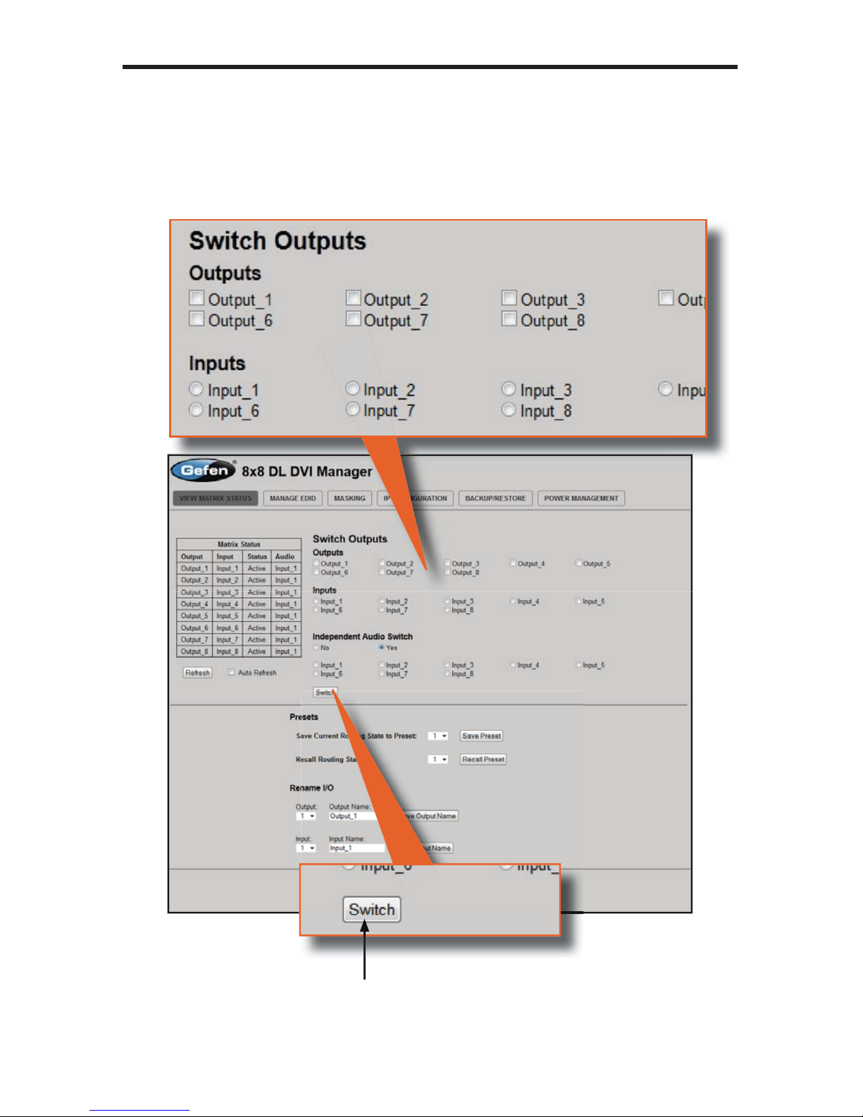
Switch Outputs
sed to route the specifi ed input to the selected output(s). To route a source,
lace a check mark next to each Output. Next, click the radio button next to
the desired Input. Press the Switch button to apply the routing change.
Switch
lick this button to apply the routing change.
Page 65

6
1
WEB INTERFA
CE
Recall Prese
t
lick the down-arrow on the pull-down list to select
the routing state (1-8) to recall. Click the Recall
Preset button to recall the preset.
Save Prese
t
lick the drop-down list to select
the preset location (1-8).
ck
the
Sa
ve
Pre
set
bu
tton to
ave the preset.
reset
s
rovides sav
ing
and
ecalling of routin
g
tates.
Drop-down list
p
Page 66

62
WEB INTERFA
CE
Save Output Nam
e
elect the DVI output to rename from the pull-down list. Type the
ame of the output in the Output Name fi eld. Click the Save Output
Name button to save changes. See page 54 for naming restrictions.
elect the DVI input to rename from the pull-down list. Type the name of
the input in the Input Name fi eld. Click the Save Input Name button to save
hanges. See page 53 for naming restrictions.
t
ename I/O
rovides custom namin
g
each i
npu
t and out
on
he matrix.
Pull-down list
Page 67

6
3
WEB INTERFA
CE
anage EDI
D
et Input to Default EDID
DID Status
Displays the current EDID status for each input on the matrix and
indicates the current Lock State.
Refresh
lick to refresh
the Matrix Status
Auto Refresh
heck this box to enable
Auto Refresh. Auto Refresh
will automaticall
y
update the
creen every 10 seconds.
Page 68

6
4
WEB INTERFA
CE
Set Default EDI
D
Place a check mark next to the input(s) that should be set to the default EDID.
lick the Set Default EDID button to apply the default EDID to the selected
inputs.
Set In
p
ut to Default EDI
D
Press this button from the Manage EDID screen to access this
enu system.
Page 69

65
WEB INTERFA
CE
pload EDID
oad EDID fi l
e
Place a check mark next to the input(s) that will receive the EDID data from the
fi
le. The EDID fi le must be in .bin format. Click the Browse button to locate the
EDID on the computer. Click the Load EDID fi le button to upload the EDID fi le
to the matrix.
load EDI
D
Press this button from the Manage EDID screen to
access this menu system.
Page 70

6
6
WEB INTERFA
CE
Downl
oad
EDI
D
ownload EDID File to PC
elect the radio button next to the output, containing the EDID to be
downloaded. Click the Download EDID File to PC button to confi rm the
hange. The downloaded EDID fi le will be in .bin format.
ownload EDI
D
Press this button from the Manage EDID screen to
access this menu s
y
stem.
Page 71

67
WEB INTERFA
CE
opy EDID
Select Source to Copy from / Select Input(s) to Copy t
o
lick the radio button next to the input or output containing the EDID to
opy. Note that only a single input or output can be selected at a time.
Place a check mark next to the input(s) where the EDID will be copied.
lick the Set EDID button to confi rm the operation
.
Copy EDI
D
Press this button from the Manage E
D
creen to access this menu system.
Page 72

6
8
WEB INTERFA
CE
EDID Lock State
date EDID Lock Stat
e
ecures the Local EDID and disables the automatic loadin
g
of the downstream EDID after the Matrix is powered on.
elect the radio button next to the
Off
or On option then click the
pdate EDID Lock State button to apply the change.
The EDID Lock State has no effect when the Dynamic EDID
functio
n is activated.
DID Lock Stat
e
Press this button from the Manage EDID
creen to access this menu system.
Page 73

69
WEB INTERFA
CE
askin
g
atrix Mask Status / Chan
ge
Displays the current masking status for each output.
ask
lick the Mask button to mask the selected output. If the output is already
masked then the button will read “Active” (enabled). Click the (“Active”) button
again to toggle the masking state to “Mask” (disabled).
Page 74

70
WEB INTERFA
CE
IP Confi guration
IP Settings
Assigns IP address, subnet, gateway, HTTP listening port, and Telnet port.
Note that the MAC address can not be changed. Click the Save button to
appl
y
changes. The matrix must be rebooted for the changes to take effect.
Telnet Login Settings
ets the user name and password for Telnet sessions to the matrix.
lick the Save button to apply changes.
Page 75

7
1
WEB INTERFA
CE
Backup / Restor
e
The Backup / Restore feature for the 8x8 DVIKVM Dual Link Matrix is not
urrently implemented and will be available in a future release of the fi rmware.
Page 76

72
WEB INTERFA
CE
ower Managemen
t
ower Status
Enabling this feature will store the +5V status for that input prior to shutting down
the matrix. This preserves the +5V state when the unit is restarted.
ower Stat
e
The current
ower state is
isted under
the column
titled “5 Volt”.
lick these
ttons to
toggle the
input power
tate.
Refresh
lick to refresh
the Power
tatus scree
n
Save Changes
lick to save the
ower lock status.
Auto Refresh
heck this box
to automaticall
y
pdate the
creen every 10
nds.
WARNING: Use caution when applying power to inputs, as this
ay damage your equipment.
Page 77

7
3
WEB INTERFA
CE
ower Lock Stat
e
In the case of an accidental power loss to the matrix, the +5V state for each
input can be preserved.
et the specifi ed Power Status buttons (see previous page) and click the
adio button next to ON. Click the Update Power Lock State button to appl
y
hanges.
By default, this option is set to
Off.
Page 78

7
4
NETWORK CABLE WIRING DIAGRA
M
efen recommends the TIA/EIA-568-B wiring option. Please adhere to the table
below when fi eld-terminating the cable for use with Gefen products.
in Color
range / Whit
e
ran
ge
reen / Whit
e
4Bl
ue
Blue / Whit
e
ree
n
Brown / Whit
e
Brow
n
abling comes in stranded and solid core types. Gefen recommends using solid
ore cabling.
It i
s recommended to use one co
ntin
uous run from one end to
the other.
onnecting through a patch is not recommended.
Page 79

75
FIRMWARE UPDAT
E
Firmware Update Procedur
e
The following items are required to update fi rmware
:
•
-232 Terminal (e.g. Windows-based PC running HyperTerminal).
•
-232 cable (do not use a null-modem cable
)
• Firmware fi les: DVI8x8 and GEFMTXFP
To begin the update procedure the matrix Boot Loader must be activated. To
activate the Boot Loader please follow the procedure below
:
1. Power-on the matrix.
2.
onnect an RS-232 cable to the PC and open the terminal program using
the following settings
:
Baud rate: 192
00
top bits:
1
Data bits:
8
Flow control: Non
e
. Type the command:
activebolo
Two options will be provided
:
To download the fi le DVI8x8 please type the command ‘activebolo 0’
To download the fi le GEFMTXFP please type the command ‘activebolo 1’
4. Type the command:
activebolo
0
This will begin the update process of the main board.
.
nce the Boot Loader is activated the following message should appear
:
. Press [1] on the computer keyboard to begin downloading program to the
temporary memor
y
VI8x8 Boot Loadin
g
================= Main Menu ===========================
ownload new program -------- 1
ncel ----------------------
2
7. Press [1] on the computer keyboard to begin downloading program to the
temporary memory.
Page 80

7
6
FIRMWARE UPDAT
E
. A message will appear in the terminal program
:
Waiting
for the fi le to be sent ... (press ‘a’ to abort)
. In Hyperterminal, click Transfer > Send fi le...
10.
lick Browse... and select the .BIN fi le corresponding to the boot loader
which was activated. In this fi rst case, the fi le should start with DVI8x8.
11.
elect Ymodem for the protocol.
12. Press Send on the Send File dialog box.
13. A message will appear in Hyperterminal
:
rogramming Completed Successfull
y!
14. The unit will exit the
boo
t l
oader screen and retu
rn to the standard
perterminal window
.
15.
epeat steps 3 - 12 for the fi le GEFMTXFP.
Page 81

77
RACK MOUNT SAFETY INFORMATIO
N
.
aximum recommended ambient temperature: 45 ˚C (104 ˚F).
. Incr
ease
the air fl ow as n
eeded to ma
intain the r
ecommended
temperature inside the rack.
. Do not exceed maximum weight loads for the rack. Install heavier
quipment in the lower part of the rack to maintain stability.
.
onnect a bonding wire between an approval safety ground stu
d
n the ch
assis
.
Page 82

7
8
SPECIFICATION
S
aximum Pixel Clock...........................................................................2 x 165 MHz
Input Video
Sig
nal................................................................................1.2 volts p-
p
Input DDC Signal...........................................................................5 volts p-p (TTL
)
DVI Input Connectors.......................................................... (8) DVI-I 29 pin femal
e
DVI Output Connectors....................................................... (8) DVI-I 29 pin femal
e
IR Extender................................................................................3.5 mm mini-stere
o
-232 Interface..................................................................................DB-9 femal
e
IP Interface.....................................................................................................RJ-4
5
Power Supply........................................................100 ~ 240 V AC (IEC connector
)
Power Consumption........................................................................70 Watts (max.
)
Operating Temperature...............................................0 ˚C ~ 45 ˚C / 32 ˚F ~ 113 ˚F
torage Temperature...............................................-20 ˚C ~ 60 ˚C / -4 ˚F ~ 140 ˚F
elative Humidity...............................................20% ~ 90% RH (no condensation
)
ack Size............................................................................................................2
U
Dimensions.......................................................................19.0” W x 3.5” H x 4.2”
D
hipping Weight.........................................................................................28.1 lbs.
Page 83

79
WARRANTY
efen warrants the equipment it manufactures to be free from defects in material
and workmanship.
I
f
equipment fails because of such defects and Gefen is notifi ed within two (2)
y
ears from the date of shipment, Gefen will, at its option, repair or replace the
quipment, provided that the equipment has not been subjected to mechanical,
lectrical, or other abuse or modifi cations. Equipment that fails under conditions
other than those covered will be repaired at the current price of parts and labor in
ect at the time of repair. Such repairs are warranted for ninety (90) days from
the day of reshipment to the Buyer.
This warranty is in lieu of all other warranties expressed or implied, including
without limitation, any implied warranty or merchantability or fi tness for any
articular purpose, all of which are expressly disclaimed.
1. Proof of sale may be required in order to claim warranty.
2.
ustomers outside the US are responsible for shipping charges to and from
efen.
.
opper cables are limited to a 30 day warranty and cables must be in their
original condition.
The information in this manual has been carefully checked and is believed to
be accurate. However, Gefen assumes no responsibility for any inaccuracies
that may be contained in this manual. In no event will Gefen be liable for
direct, indirect, special, incidental, or consequential damages resulting from
any defect or omission in this manual, even if advised of the possibility of such
damages. The technical information contained herein regarding the features and
pecifi cations is subject to change without notice.
For the latest warranty coverage information, refer to the Warranty and Return
Policy under the Support section of the Gefen Web site at www.gefen.com.
RODUCT REGISTRATIO
N
lease register your product online by visiting the Register Product page
nder the Support section of the Gefen Web site
.
Page 84

0
ICENSIN
G
wIP is licenced under the BSD licence
:
opyright (c) 2001-2004 Swedish Institute of Computer Science.
All rights reserved.
edistribution and use in source and binary forms, with or without modifi cation,
are permitted provided that the following conditions are met
:
1.
edistributions of source code must retain the above copyright notice, this
ist of conditions and the following disclaimer.
2.
edistributions in binary form must reproduce the above copyright notice,
this list of conditions and the following disclaimer in the documentation and
/
or other materials provided with the distribution.
. The name of the author may not be used to endorse or promote products
derived from this software without specifi c prior written permission.
THIS SOFTWARE IS PROVIDED BY THE AUTHOR ``AS IS’’ AND ANY
EXPRESS OR IMPLIED WARRANTIES, INCLUDING, BUT NOT LIMITED TO,
THE IMPLIED WARRANTIES OF MERCHANT ABILITY AND FITNESS FOR
A PARTICULAR PURPOSE ARE DISCLAIMED. IN NO EVENT SHALL THE
AUTHOR BE LIABLE FOR ANY DIRECT, INDIRECT, INCIDENTAL, SPECIAL
,
EXEMPLARY, OR CONSEQUENTIAL DAMAGES (INCLUDING, BUT NOT
LIMITED TO, PROCUREMENT OF SUBSTITUTE
GOODS OR S
ERVICES;
L
OSS O
F USE, DATA, OR PROFITS; OR BUSINESS INTERRUPTION
)
WEVER CAUSED AND ON ANY THEORY OF LIABILITY, WHETHER I
N
NTRACT, STRICT LIABILITY, OR TORT (INCLUDING NEGLIGENCE OR
THERWISE) ARISING IN ANY WAY OUT OF THE USE OF THIS SOFTWARE,
EVEN IF ADVISED OF THE P
OSS
IBILITY OF
SUC
H DAMAGE.
Page 85

Page 86

Page 87

Page 88

Rev A
5
Nordhoff St., Chatsworth CA 9131
1
1-
800-545-6900
818-772-9100 fax: 818-772-91
20
w
ww.gefenpro.com support@gefenpro.co
m
Pb
 Loading...