

Page 1

1080P
16x16 DVI Matrix
w/ Push Button
Control
GEF-DVI-16416-PB
User Manual
www.gefenpro.com
Page 2

Page 3

ASKING FOR ASSISTANCE
Technical Support:
Telephone (818) 772-9100
(800) 545-6900
Fax (818) 772-9120
Technical Support Hours:
8:00 AM - 5:00 PM Monday through Friday, Pacic Time
For 24 / 7 support, see the front panel of the product for the support number
Write To:
Gefen, LLC
c/o Customer Service
20600 Nordhoff St
Chatsworth, CA 91311
www.gefenpro.com
support@gefenpro.com
Gefen, LLC reserves the right to make changes in the hardware, packaging, and any
accompanying documentation without prior written notice.
16x16 DVI Matrix w/ Push Button Control
is a trademark of Gefen LLC
© 2015 Gefen, LLC. All rights reserved.
All trademarks are the property of their respective owners.
Notice
Rev A11
Page 4

CONTENTS
1 Introduction
2 Operation Notes
3 Features
4 Front Panel Layout
5 Front Panel Descriptions
6 Back Panel Layout
7 Back Panel Descriptions
8 IR Remote Description
9 IR Remote Installation
10 IR Code Conguration
11 Connecting And Operating The 16x16 DVI Matrix w/ Push Button Control
11 Wiring Diagram
12 Front Panel Display
13 Routing
13 Routing Inputs to Outputs
14 Getting the Current Routing Status of an Input
15 Getting the Current Routing Status of an Output
15 One-to-One Routing
16 Presets
16 Saving the Current Routing State
18 Recalling a Saved Routing State
20 Masking
20 Masking Outputs
22 Getting the Current Masking State
23 Unmasking Outputs
25 Locking the Matrix
26 EDID Management
26 Saving the Downstream EDID to an Input
28 Saving the Default EDID to an Input
30 RS-232 / IP Control
30 RS-232 Interface
30 RS-232 Settings
31 Using Syner-G
33 RS-232 / Telnet / UDP Commands
33 EDID Management
38 IP Conguration
47 Routing
50 Masking
52 Miscellaneous
60 Web Interface
60 View Matrix Status
64 Manage EDID
70 Masking
71 IP Conguration
73 Backup / Restore
74 Power Management
76 Network Cable Wiring Diagram
77 Rack Mount Safety Information
78 Specications
79 Warranty
80 Licensing
Page 5

INTRODUCTION
Congratulations on your purchase of the GefenPRO 16x16 DVI Matrix w/ Front Panel Push
Button Control. Your complete satisfaction is very important to us.
GefenPRO
In the realm of video distribution, certain features are invaluable in a commercial or
broadcast environment. Accommodations such as a build-in power supply and at black
rack-mount enclosures set GefenPRO apart from our traditional products. Complex
distribution units allow for professional DVI, 3G-SDI, and HDMI signals to be routed and
converted easily and seamlessly, while being backed up by a renowned and dependable
technical support team. Gefen invites you to explore the GefenPRO product line and hopes
that you nd the solution that ts your needs.
The GefenPRO 16x16 DVI Matrix w/ Front Panel Push Button Control
Simplify the process of routing up to 16 DVI sources to any of 16 DVI monitors without
losing quality or resolution. This Matrix provides a simple, reliable, and highly effective
method of streamlining any installation using multiple sources and outputs, taking the
hassle out of managing multiple connections. Each DVI source is accessible at all times
by any monitor using the front-panel buttons, IR remote unit, built-in RS-232 or using IP
control.
How It Works
Connect 16 sources to the DVI input ports on the Matrix using the supplied DVI cables.
Connect 16 monitors to the Matrix. Power on the source devices and the monitors. Plug
in the power cord and power on the Matrix. Use the push buttons on the front panel for
routing each DVI source to the desired display. The connected monitors will display video
according to the routing state.
NOTE: This Matrix only supports DVI-D. The DVI connectors on the Matrix all have 29
pins.
1
Page 6

OPERATION NOTES
OPERATING THE GEFENPRO 16X16 DVI MATRIX W/ FRONT PANEL PUSH BUTTON
• The 16x16 DVI Matrix w/ Push Button Control does not support HDCP content.
• Make sure that a DVI monitor is powered and connected to one of the DVI outputs on
the 16x16 DVI Matrix w/ Push Button Control before applying power. By default, the
Local EDID is read from the connected monitor and is copied to all 16 DVI inputs once
the Matrix has been turned on. If a monitor is not detected by the Matrix at power-on,
a default (internal) EDID of 640x480 will be used. This functionality can be disabled
using the Secure Local EDID function using RS-232 or IP control.
• There is no internal scaling in the 16x16 DVI Matrix w/ Push Button Control. Each
monitor attached to the Matrix must be able to display the resolutions output by the
source device(s).
For maximum compatibility it is recommended that only one common resolution
be used by each source device.
• Advanced EDID features and IP conguration features are accessible through the
RS-232 serial command set.
• Routing and EDID features can be managed using the built-in IP control feature.
• This matrix supports Dynamic EDID. See page 61 for details.
• The Gefen Syner-G Software Suite is a free downloadable application from Gefen that
provides automatic download and installation of rmware upgrades for this product.
Download the application here: http://www.gefen.com/synerg/
READ THESE NOTES BEFORE INSTALLING OR
CONTROL
• The Gefen Matrix Switcher Keyboard Controller is a free downloadable application
from Gefen that allows a computer keyboard to be used to switch between sources.
This application uses the Telnet protocol to control any Gefen switcher or matrix that
uses IP control.
Download the application here: http://www.gefen.com/support/download.jsp
IMPORTANT: If the unit is installed in a closed or multi-rack
assembly, do not block the ventilation holes of the enclosure.
2
Page 7

FEATURES
Features
• Supports resolutions up to 1920 x 1200
• Front-panel push buttons for local switching
• Front-panel LCD Display
• Switching is controlled via front panel buttons, IR remote, IP, or RS-232 commands
• Compatible with the Gefen Keyboard Controller software
• Advanced EDID management
• Programmable routing presets
• Standby mode
• Output masking control
• IP control and conguration with built-in Web server
• Internal power supply
• Rack-mountable
Package Includes
(1) GefenPRO 16x16 DVI Matrix w/ Front Panel Push Button Control
(16) 6 ft. DVI cables (M-M)
(1) IR Remote Control Unit
(1) AC Power Cord
(1) Quick-Start Guide
3
Page 8
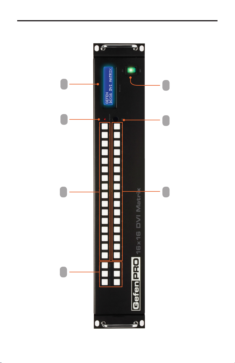
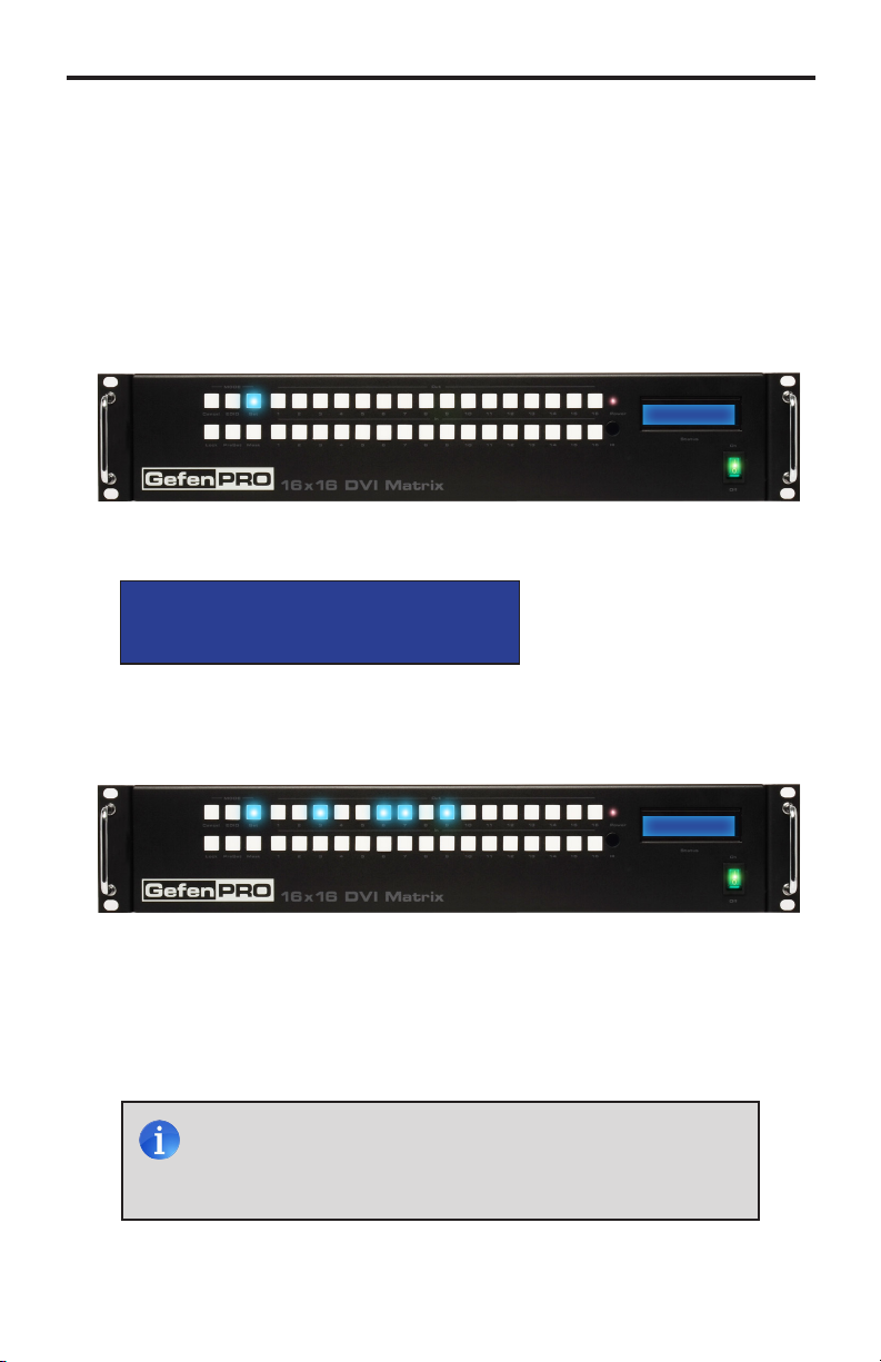
PANEL LAYOUT
Front Panel
4
3
2
1
6 57
4
Page 9

PANEL DESCRIPTIONS
Front Panel
1 Mode Buttons
These buttons are used to control routing, masking, presets on the matrix. See the
information beginning with page 12 for more information.
2 Output Buttons (1 - 16)
Used for routing an Input to an Output. Each of these buttons represents an Output.
See page 13 for more information on routing DVI sources.
3 Power Indicator
This LED indicator will glow red when the power is turned on.
4 LCD Display
Displays the current routing status of the Matrix and is also used to manage source
routing.
5 Power
Used to power ON and power OFF the matrix.
6 IR Window
Receives signals from the IR Remote Control unit.
7 Input Buttons (1 - 16)
Used for routing an Input to an Output. Each of these buttons represents an Input.
See page 13 for more information on routing DVI sources.
5
Page 10
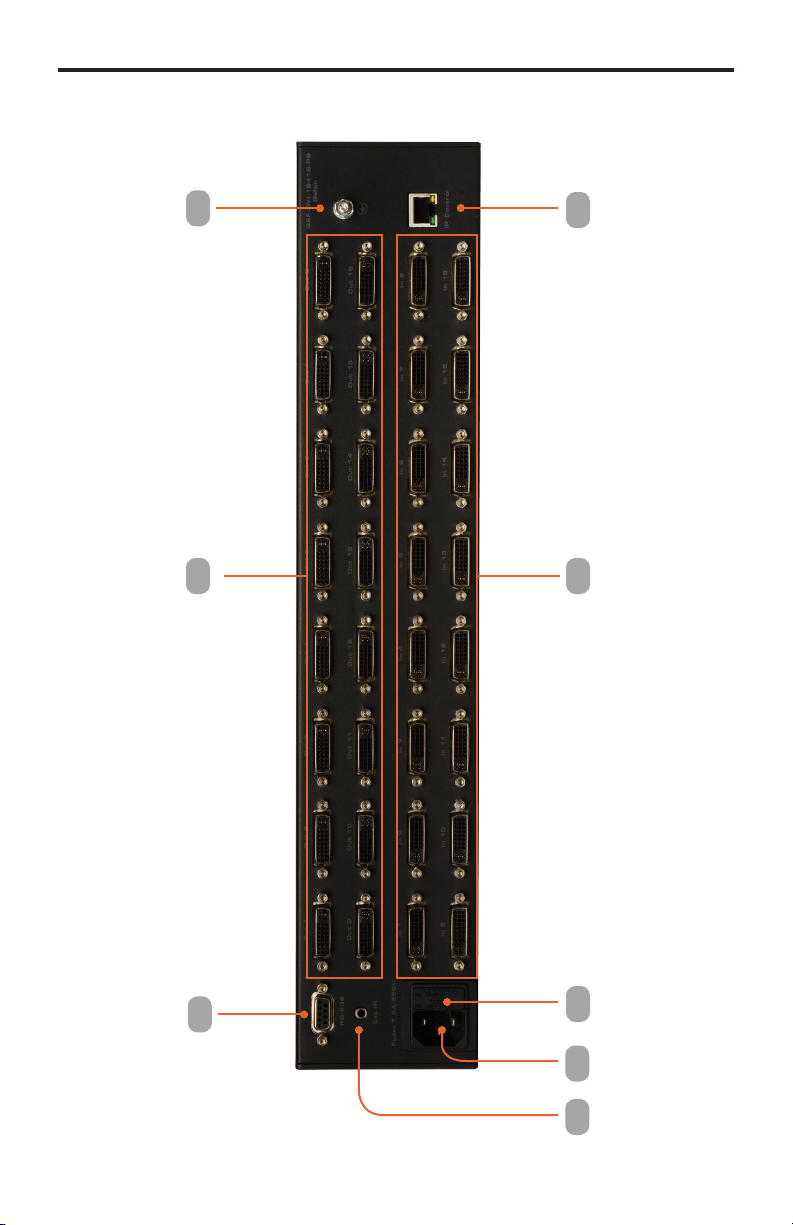
PANEL LAYOUT
Back Panel
6
7
53
4
8
1 2
6
Page 11

PANEL DESCRIPTIONS
Back Panel
1 IR Extender Port
Connect an optional IR extender to this port.
2 AC 110 / 220 V AC (50/60 Hz) Power Cable Receptacle
Connect the included AC power cord from this receptacle to an available electrical outlet.
3 Fuse Drawer
Each power receptacle houses a fuse drawer. Within each fuse drawer are two (2) 250 V
fuses. One fuse is active and the other is a spare.
4 DVI Input Ports (1 - 16)
Connect DVI source devices to these ports.
5 IP Control Interface
Connect to this port to control the 16x16 DVI Matrix w/ Push Button Control using IP
Control. See page 31 for more information on conguring IP settings.
6 Grounding Terminal
Provides a discharge path to ground in case a short circuit occurs between the “hot”
lead of the power supply and the enclosure of the Matrix. The grounding wire should be
attached from the grounding terminal to an approved ground path.
7 DVI Output Ports (1 - 16)
Connect DVI monitors to these ports.
8 RS-232 Serial Port
Connects to the RS-232 control device. The 16x16 DVI Matrix w/ Push Button Control
may be switched remotely using this port. See page 30 for more information.
7
Page 12
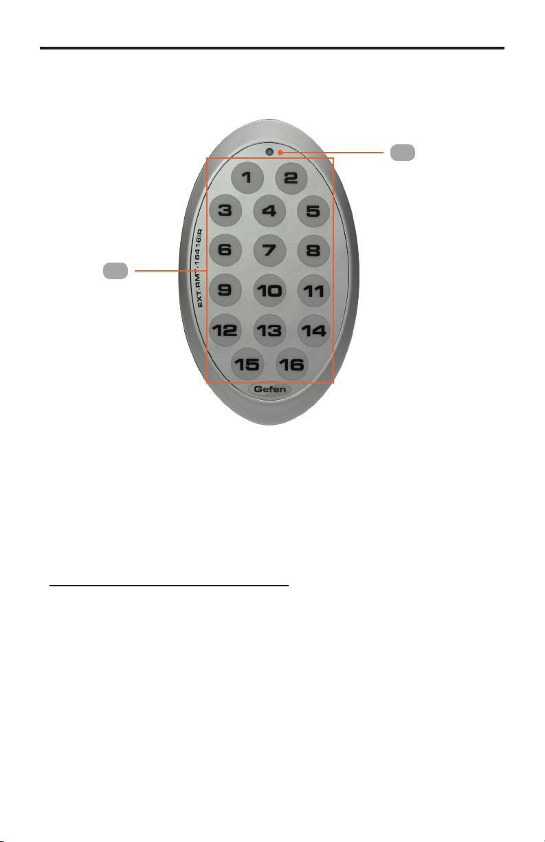
IR REMOTE DESCRIPTION
RMT-16416IR
Remote Control Unit
1
2
1 Activity Indicator
This LED will be activated momentarily each time a button is pressed.
2 Display and Source Selection Buttons (1 - 16)
These buttons are used to select which source is routed to a monitor.
Routing Sources using the Remote Control unit
Issuing a routing command is a two step process. The rst step is to select the monitor (1-16) to
which the source will be routed. The second step is to select the source (1-16).
Example:
Route the source device connected to In 6 to the monitor connected to Out 4.
1. Press button 4 (Out 4) on the IR remote control unit.
2. Press button 6 (In 6) on the IR remote control unit.
The source connected to In 6 will be routed to the monitor connected to Out 4.
8
Page 13
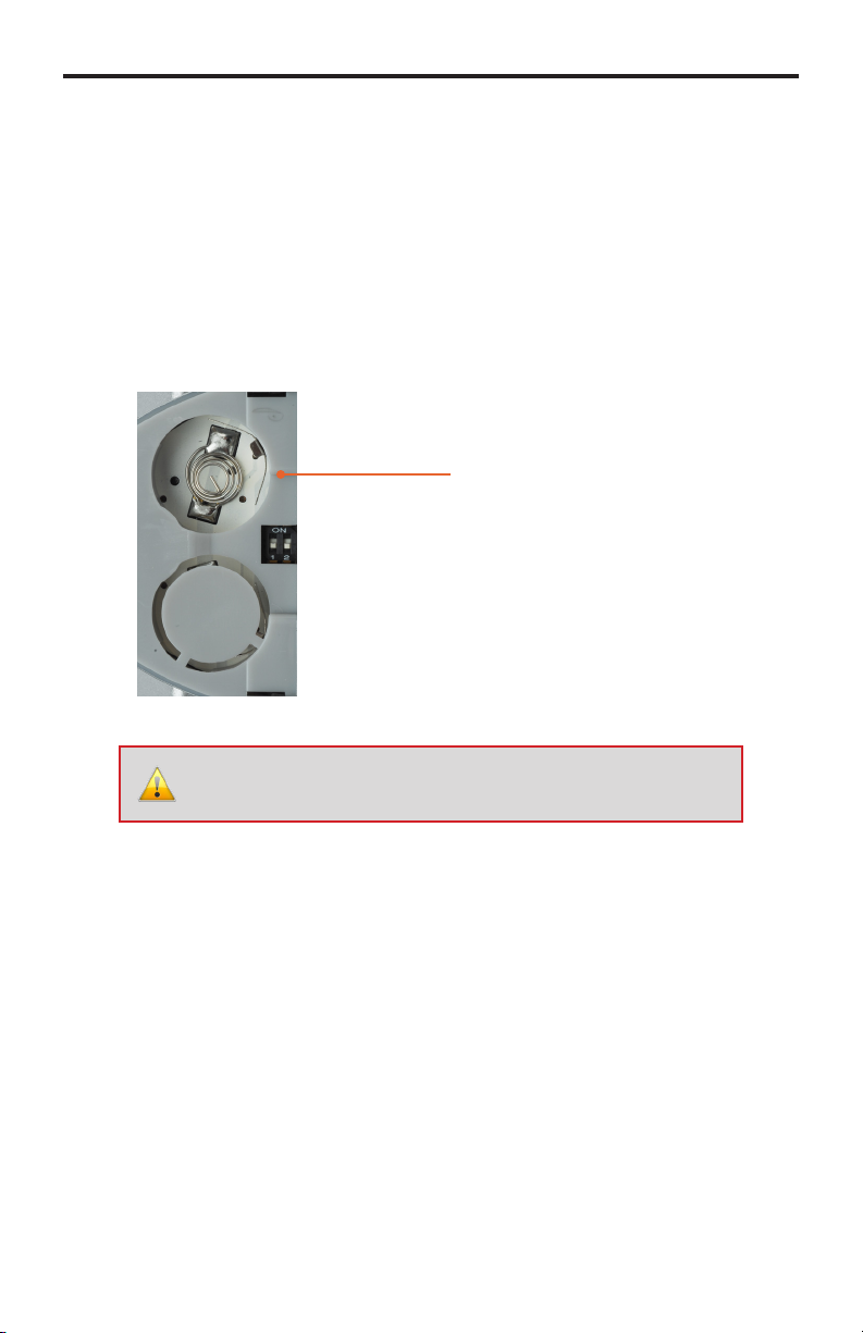
IR REMOTE INSTALLATION
Installing the RMT-16416IR Battery
1. Remove the battery cover on the back of the IR Remote Control unit.
2. Insert the included battery into the open battery slot. The positive (+) side of the
battery should be facing up.
3. Replace the battery cover.
The Remote Control unit ships with two batteries. One battery is required for operation and
the other battery is a spare.
Battery Slot
WARNING: Risk of explosion if battery is replaced by an incorrect
type. Dispose of used batteries according to the instructions.
9
Page 14
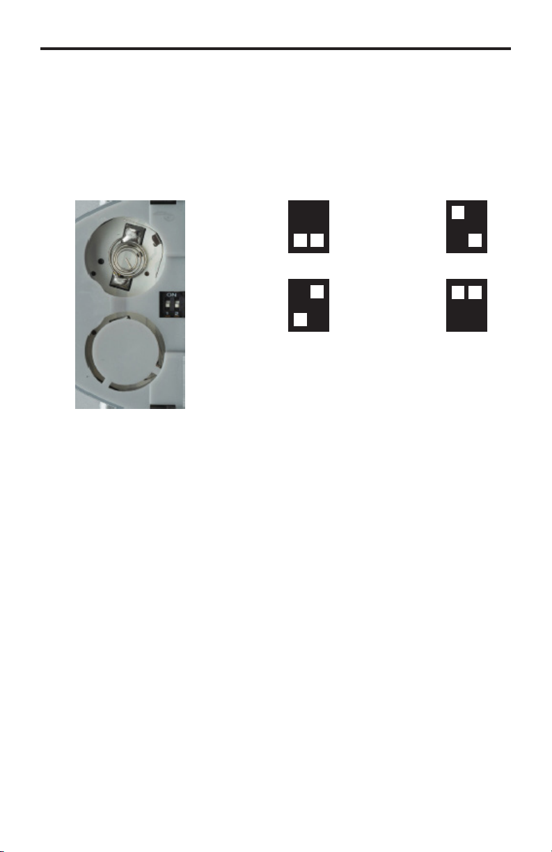
IR REMOTE CONFIGURATION
How to Resolve IR Code Conicts
In the event that IR commands from other remote controls interfere with the supplied IR
Remote Control unit, changing the IR Remote Control’s IR channel will x the problem.
The IR Remote Control unit has a bank of DIP switches used for setting the IR channel.
The DIP switch bank is located underneath the battery cover.
Remote Channel 0:
Default
1 2
Remote Channel 1:
1 2
Remote Channel 2:
1 2
Remote Channel 3:
1 2
Left: Picture of the opened rear battery compartment
of the IR remote showing the exposed DIP Switch
bank between the battery chambers.
It is important that the IR channel on the Remote Control unit, matches the IR channel set
on the 16x16 DVI Matrix w/ Push Button Control. For example, if both DIP switches on the
IR Remote Control unit are set to IR channel 0 (both DIP switches down), then the 16x16
DVI Matrix w/ Push Button Control must also be set to IR channel 0. See page 54 on how
to change the IR channel on the 16x16 DVI Matrix w/ Push Button Control.
10
Page 15
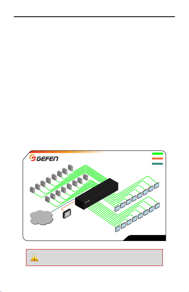
CONNECTING AND OPERATING
THE 16X16 DVI MATRIX W/ PUSH BUTTON CONTROL
How to Connect the 16x16 DVI Matrix w/ Push Button Control
1. Connect up to 16 DVI source devices to the DVI inputs on the rear panel of the 16x16
DVI Matrix w/ Push Button Control using the supplied DVI cables.
2. Connect up to 16 DVI displays to the DVI outputs on the rear panel of the 16x16 DVI
Matrix w/ Push Button Control using DVI cables.
3. Connect the included AC power cable to the power receptacle on the rear panel of the
16x16 DVI Matrix w/ Push Button Control. Connect the opposite end of the cable into
an available electrical outlet.
Wiring Diagram
16x
DVI Sources
IP Control
RS-232 Controller
Matrix
16x
DVI Displays
ATTENTION: This product should always be connected to a
grounded electrical socket.
11
DVI CABLE
RS-232 CABLE
ETHERNET CABLE
GEF-DVI-16416-PB
Page 16

FRONT PANEL DISPLAY
Main Display
The Main Display of the 16x16 DVI Matrix w/ Push Button Control is a 16 character 2
line display. This display will show the Standby Screen and will also be used to aid in
performing routing commands. When the unit is powered on, the following screen is
displayed:
EDID LOADING
PLEASE WAIT
After a few moments, the standby screen is displayed. The standby screen is shown
below:
GEFEN
16x16 DVI MATRIX
Displaying Additional Information
Pressing the Cancel button, consecutively, will cycle through other screens such as
firmware version and boot loader version:
FW 6.2
BOLO 1.6
IP ADDRESS
192.168.0.72
MAC ADDRESS
0.1C.91.1.20.6
IR ADDRESS
SW1=0 ,SW2=0
12
Page 17
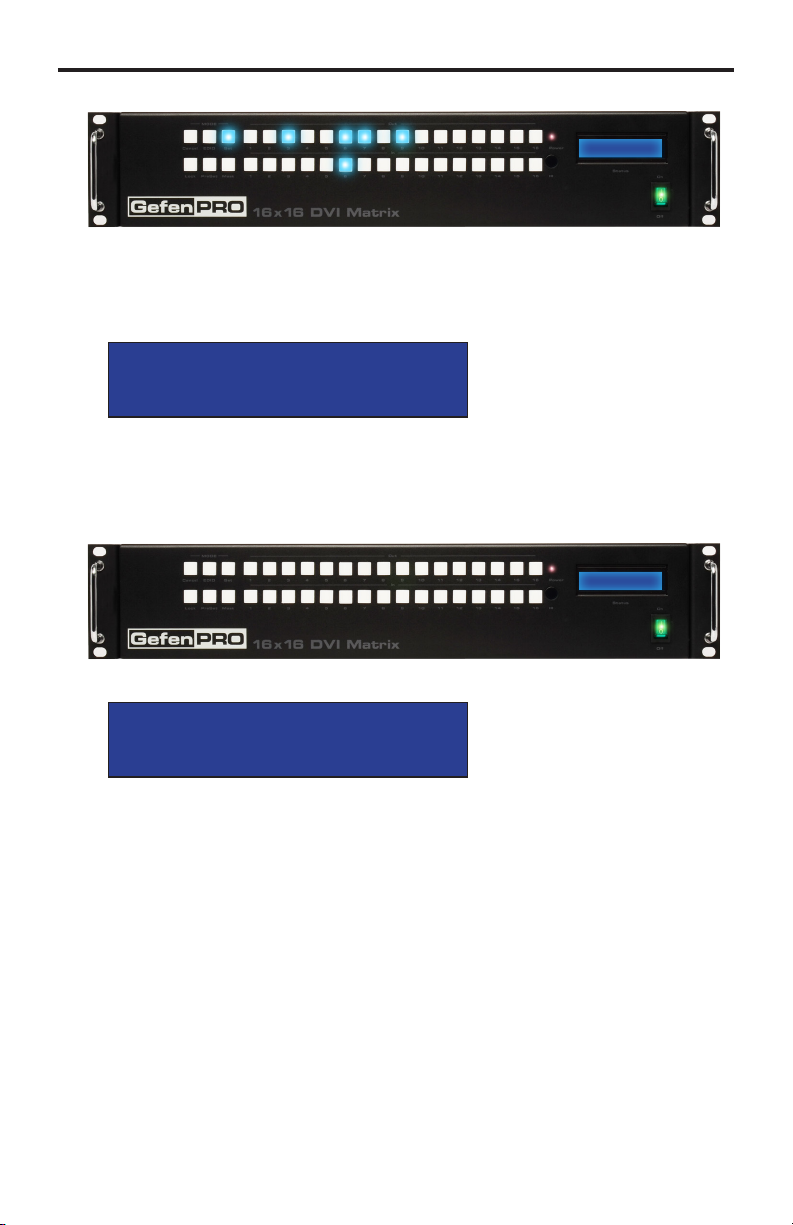
ROUTING
Routing Inputs to Outputs
The following example illustrates the routing process. An input may be routed to a single
or multiple outputs. Multiple inputs cannot be routed to a single output. For this example,
we will route Input 6 to the following outputs: Output 3, Output 6, Output 7, and Output 9.
1. Press the Set button on the front panel. Pressing the Set button tells the matrix that
we want to perform a routing, masking, or preset operation. The Set button will glow
bright blue, indicating that it has been pressed.
2. The front-panel display will indicate that routing mode is active.
ROUTING MODE
ROUTING MODE
3. First, we need to specify the outputs. Press buttons 3, 6, 7, and 9. The selected
buttons will glow bright blue.
ROUTING MODE
4. Select the desired input (source) button (1 - 16). For this example, we want to route
the source connected to Input 6 to each of the outputs in step 3. Therefore, press
button 6 on the bottom row. The selected input will glow bright blue.
NOTE: Only one input can be routed at a time. If the wrong input
button is accidentally pressed, then continue by pressing the
correct input button. The previous input button will automatically be
deselected.
13
Page 18
ROUTING
5. Press the Set button on the front panel, again, to complete the routing operation.
The front panel display will indicate that the routing process has been completed.
ROUTING COMPLETE
6. After a few moments, the selected buttons on the front panel will turn off and the
matrix will return to the standby screen.
ROUTING MODE
GEFEN
16x16 DVI MATRIX
GEFEN
16x16 DVI MATRIX
Getting the Current Routing Status of an Input
To display the current routing status of an input, press the desired input button on the front
panel of the matrix. Once the input button is pressed, the routed outputs will be displayed.
From our previous routing example, we already know that Input 6 is routed to Output 3, 6,
7, and 9. Let’s use this to illustrate how to retrieve the current routing status of an input.
(continued on next page)
14
Page 19
ROUTING
1. Press the button for Input 6 on the matrix.
2. The current routing status for Input 6 will be displayed by the front panel buttons:
3. After a few moments the buttons will automatically turn off.
To immediately dismiss the routing status and return to the standby screen, press the
Cancel button.
Getting the Current Routing Status of an Output
To display the current routing status of an output, press the desired output button on the
front panel of the matrix. Once the output button is pressed, the associated input will be
displayed. We’ll continue with the previous example.
1. Press the button for Output 3 on the matrix.
Gefen
16x16 dvi matrix
2. The current routing status for Output 3 will be displayed by the front panel buttons:
Gefen
16x16 dvi matrix
3. After a few moments the buttons will automatically turn off.
To immediately dismiss the routing status and return to the standby screen, press the
Cancel button.
One-to-One Routing
When an input-output pair share the same number, it is called “one-to-one” routing.
By default, the 16x16 DVI Matrix w/ Push Button Control is shipped in “one-to-one” mode.
This means that Input 1 is routed to Output 1, Input 2 is routed to Output 2, and so on.
15
Page 20
PRESETS
Saving the Current Routing State
The 16x16 DVI Matrix w/ Push Button Control allows routing (and masking) states to be
saved to internal non-volatile memory. Each routing state can be recalled at a later time
(see Recalling a Saved Routing State). Even if the matrix is powered OFF, the presets will
be retained in memory.
We’ll illustrate an example by saving the routing state of Input 6, which we created
on page 13.
1. Press the PreSet button, twice. The PreSet button will glow bright blue, indicating
that it has been pressed. The front-panel display will indicate that the matrix is in
“save preset” mode:
ROUTING MODE
SAVE CURRENT SET
PRESET MODE
SAVE CURRENT SET
2. Select a preset memory location by pressing any of the rst eight input buttons (1 - 8).
The matrix supports up to eight preset locations. For this example, press the button 1.
PRESET MODE
SAVE CURRENT SET
3. Press the Set button to store the preset.
Set button
PRESET MODE
SAVE CURRENT SET
(continued on next page)
16
Page 21

PRESETS
4. The Set button will ash momentarily and the front-panel display will indicate that the
preset has been saved.
Preset mode
complete
5. After a few moments, the front-panel display will display the standby screen.
GEFEN
16x16 DVI MATRIX
GEFEN
16x16 DVI MATRIX
17
Page 22
PRESETS
Recalling a Saved Routing State
The 16x16 DVI Matrix w/ Push Button Control allows saved routing (and masking) states
to be recalled from memory for instant access. In this example, we will recall the routing
preset that we stored in the previous example. In order to clearly see how this process
works, try changing the routing state of Input 6 to Output 2. Then, use the steps below to
recall the original routing state.
1. Press the PreSet button, once. The PreSet button will glow bright blue, indicating that
it has been pressed. The front-panel display will indicate that the matrix is in “recall
preset” mode:
ROUTING MODE
recall saved SET
PRESET MODE
recall saved set
2. Since we stored our preset in Preset 1, press the button for Input 1 to recall the
routing state.
PRESET MODE
recall saved set
3. Press the Set button to recall the routing state from the selected location.
Set button
PRESET MODE
recall saved SET
18
Page 23

PRESETS
4. The Set button will ash momentarily and the front-panel display will indicate that the
preset has been recalled.
Preset mode
complete
5. After a few moments, the front-panel display will display the standby screen.
GEFEN
16x16 DVI MATRIX
GEFEN
16x16 DVI MATRIX
19
Page 24

MASKING
Masking Outputs
“Masking” prevents the output device (display, etc) from receiving an output signal.
Instead of powering-down or disconnecting the output device, individual or multiple
outputs can be masked. Inputs cannot be masked.
To illustrate masking, we’ll use our original routing example from the section Routing Inputs
to Outputs.
1. Press the Mask button. The Mask button will glow bright blue and the front-panel
display will indicate that the matrix is in mask mode.
mask mode
mask mode
2. Select the desired outputs to be masked. In this example, we will select Output 5
and Output 6. Each output button will glow bright blue as they are pressed.
mask mode
3. Press the Set button to mask the selected outputs. The Set button will ash
momentarily.
Set button
mask mode
(continued on next page)
20
Page 25

MASKING
4. Once the Set button is pressed, the front-panel display will indicate that the masking
process was successful:
mask mode
mask completed
5. After a few moments, the selected buttons will turn off and the front-panel display will
return to the status screen.
GEFEN
16x16 DVI MATRIX
GEFEN
16x16 DVI MATRIX
21
Page 26
MASKING
Getting the Current Masking Status
If the masking state is unknown, it can be queried using the Mask button. Alternatively, the
masking state can be retrieved through the Web Interface or by using the m command.
1. Press the Mask button. The Mask button will glow bright blue and the front-panel
display will indicate that the matrix is in mask mode.
If any outputs are currently masked, they will be indicated on the front panel.
For example, since we recently masked Output 5 and Output 6, these buttons will
glow bright blue, as shown below.
mask mode
mask mode
2. After a few moments, the selected buttons will turn off and the front-panel display will
return to the standby screen.
GEFEN
16x16 DVI MATRIX
GEFEN
16x16 DVI MATRIX
22
Page 27

MODE BUTTONS
Unmasking Outputs
Once an output (or multiple outputs) has been masked, it can be unmasked.
Unmasking an output will allow the video signal to be displayed after a masking operation.
We’ll continue with our previous example and unmask Output 5 and Output 6.
1. Press the Mask button. The Mask button will glow bright blue and the front-panel
display will indicate that the matrix is in mask mode.
Once the mask button is pressed, any outputs that have been masked will be
indicated on the front panel.
mask mode
mask mode
2. Press the desired output button(s) to unmask the output. In our case, we will select
both Output 5 and Output 6. Each button will turn off as it is pressed.
mask mode
3. Press the Set button. The Set button will ash momentarily.
Set button
mask mode
23
Page 28

MODE BUTTONS
4. Once the Set button is pressed, the front-panel display will indicate that the
unmasking process was successful:
mask mode
mask completed
5. After a few moments, the matrix will return to the standby screen.
GEFEN
16x16 DVI MATRIX
GEFEN
16x16 DVI MATRIX
24
Page 29

LOCKING THE MATRIX
Locking the matrix will prevent any changes by disabling all buttons (except the Lock
button) on the front panel. This feature is useful in preventing routing or other changes
caused by accidentally pressing the buttons on the front panel.
1. Press the Lock button. The Lock button will glow bright blue, indicating that the
matrix is now locked. The front-panel display will also indicate that the matrix has
been locked.
lock mode
2. To unlock the matrix, press the Lock button again. The Lock button will turn off and
the front-panel display will return to the standby screen.
GEFEN
16x16 DVI MATRIX
lock mode
GEFEN
16x16 DVI MATRIX
25
Page 30

EDID MANAGEMENT
The 16x16 DVI Matrix w/ Push Button Control incorporates EDID management support.
Basic EDID functions, such as storing EDID data to inputs can be performed using the
buttons on the front panel. Advanced EDID management features are controlled through
the Web interface or by using EDID Management commands.
Saving the Downstream EDID to an Input
1. Press the EDID button, once. The EDID button will glow bright blue and the front-
panel display will indicate that the matrix is ready to copy the downstream EDID.
EDID DSTOLO MODE
EDID DSTOLO MODE
DSTOLO is an abbreviation for “DownStream TO LOcal”.
2. Press the desired output. For this example, we are going to use the EDID of the
display that is connected to Output 7. Therefore, we will press the button for Output 7.
EDID DSTOLO MODE
(continued on next page)
26
Page 31

EDID MANAGEMENT
3. Select the desired input where the EDID will be stored. We will arbitrarily select
Input 4, by pressing button 4.
4. Press the Set button. The Set button will ash momentarily.
Set button
EDID DSTOLO MODE
EDID DSTOLO MODE
5. Once the Set button is pressed, the matrix will begin copying the downstream EDID
from the display (or other sink) to the EDID from the selected output to the specied
input.
The front-panel display will indicate that the matrix is copying the EDID:
EDID LOADING
PLEASE WAIT
6. After the EDID has been successfully copied to the selected input, the front-panel
display will show the following message:
EDID LOADING
Copy COMPLETE
27
Page 32

EDID MANAGEMENT
Saving the Default EDID to an Input
There may be instances when the downstream EDID data is corrupt or the EDID is not being read correctly by the matrix. On the other hand, it may be desirable to use a “generic”
EDID as opposed to the downstream EDID. In any case, the matrix provides a default
(internal) EDID that can be used. Let’s look at an example.
1. Press the EDID button, twice. The EDID button will glow bright blue and the
front-panel display will indicate that the matrix is ready to copy the default EDID
to the specied input.
EDID DETOLO MODE
DETOLO is an abbreviation for “DEfault TO LOcal”.
EDID DETOLO MODE
2. Select the input where the default EDID will be copied. For this example, we will
copy the default EDID to Input 5. Therefore, we will press the button for Input 5.
EDID DETOLO MODE
(continued on next page)
28
Page 33

EDID MANAGEMENT
3. Press the Set button. The Set button will ash momentarily.
4. Once the Set button is pressed, the matrix will begin copying the default EDID
to the specied input.
The front-panel display will indicate that the matrix is copying the EDID:
EDID LOADING
PLEASE WAIT
5. After the EDID has been successfully copied to the selected input, the front-panel
display will show the following message:
EDID LOADING
Copy COMPLETE
Set button
EDID DETOLO MODE
6. After a few moments, the selected buttons will turn off and the front-panel display will
return to the status screen.
GEFEN
16x16 DVI MATRIX
29
Page 34

RS-232 / IP CONTROL
DE-9
RS-232 Interface
564738291
RS-232 Controller Matrix
DCD
RXD
TXD
DTR
GND
DSR
RTS
CTS
R1
1
2
3
4
5
6
7
8
9
1
2
3
4
5
6
7
8
9
DCD
RXD
TXD
DTR
GND
DSR
RTS
CTS
R1
Only TXD, RXD, and GND are used.
RS232 Settings
Baud rate .......................................................................................................................19200
Data bits ............................................................................................................................... 8
Parity bits ....................................................................................................................... None
Stop bits ................................................................................................................................1
Flow Control ................................................................................................................... None
IMPORTANT: When sending RS-232 commands, a carriage return
must be included at the end of the command. A space must be
included between the command and the parameter.
30
Page 35

RS-232 / IP CONTROL
Using Syner-G
When using this product for the rst time, it is recommended that the unit be congured
using the Gefen Syner-G™ Software Suite. The Gefen Syner-G™ Software Suite is free
software that is available from the Gefen Web site.
1. Download and install the Gefen Syner-G™ Software Suite. Download the application
here: http://www.gefen.com/synerg/
2. Connect an Ethernet cable from the network to the IP control port on the product.
3. Launch the Gefen Syner-G™ Software Suite.
4. Click the GEF-DVI-16416-PB from the product list.
31
Page 36

RS-232 / IP CONTROL
5. Under the Device Settings section, enter the desired IP address, subnet mask,
gateway IP address, Web GUI port, and Telnet port in the supplied elds.
If desired, the Description eld can be changed as well. This is useful to identify if
you have multiple units running on a network.
6. Click the Save button at the bottom right-corner of the screen.
7. Click the Reboot button.
8. Click the Web GUI link, above the Reboot button, to access the built-in web interface.
The following table lists the default IP settings for this product.
Description Address / Port Description Address / Port
IP Address
Subnet
192.168.1.72
255.255.255.0
Gateway
HTTP Port
192.168.1.1
80
32
Page 37

RS-232 / TELNET / UDP COMMANDS
EDID Management
Command Description
#dynamic_edid Enables / disables dynamic EDID
#edidbatolo Read downstream EDID and stores in any Local Input
#ediddetolo Sets Local EDID to Default EDID
#ediddstoba Read downstream EDID and stores in EDID Bank
#ediddstolo Read downstream EDID and stores into a Local EDID
#lock_edid Secures Local EDID
#prbaedid Read EDID from an EDID bank and sends to serial port
#prdsedid Read downstream EDID and sends to serial port
#predidst Prints EDID details
#prloedid Read Input Local EDID and sends to serial port
#dynamic_edid Command
The #dynamic_edid command provides the ability to route any downstream EDID to any
input. When enabled, the EDID is copied to all inputs from the last selected active output.
When disabled, the EDID is copied to all inputs from the rst active display detected,
starting from Output 1.
Syntax:
#dynamic_edid param1
Parameters:
param1 Value [0 ... 1]
Default:
Disabled
Value Meaning
0 Disable
1 Enable
33
Page 38

RS-232 / TELNET / UDP COMMANDS
#edidbatolo Command
The #edidbatolo command reads the downstream EDID and stores it to any local input.
Syntax:
#edidbatolo param1 param2 [param3...param9]
Parameters:
param1 EDID bank offset [1 ... 5]
param2 Input [1 ... 16]
Notes:
If param2 = 0, then the EDID in the specied bank is copied to all eight inputs.
#ediddetolo Command
The #ediddetolo command stores the Default EDID (640x480) in the specied Local EDID
inputs.
Syntax:
#ediddetolo param1 param2 param3...param9
Parameters:
param1 Input [1 ... 16]
Notes:
If param1 = 0, then all 16 DVI inputs will be set to the Default EDID.
34
Page 39

RS-232 / TELNET / UDP COMMANDS
#ediddstoba Command
The #ededdstoba command reads the downstream EDID and stores it to a specied
EDID bank.
Syntax:
#ediddstoba param1 param2
Parameters:
param1 A downstream monitor [1 ... 16]
param2 EDID bank offset [1 ... 3]
#ediddstolo Command
The #ediddstolo command reads the downstream EDID and stores it to a Local EDID input.
Syntax:
#ediddstolo param1 param2 [param3...param9]
Parameters:
param1 A downstream monitor [1 ... 16]
param2 Input list [1 ... 16]
Notes:
If param2 = 0, then the downstream EDID is stored to all 16 DVI inputs. If more than eight
inputs need to be specied in order to receive the downstream EDID, the #ediddstolo
command must be executed twice.
Example:
#ediddstolo 2 1 2 3 4 5 6 7 8 9 10 11 (not permitted!)
Instead, run the function twice:
#ediddstolo 2 1 2 3 4 5 6 7 8
#ediddstolo 2 9 10 11
35
Page 40

RS-232 / TELNET / UDP COMMANDS
#lock_edid Command
The #lock_edid command secures the Local EDID and disables the automatic loading of
the downstream EDID after the matrix is powered on. This feature can also be controlled
using the Web Interface (see page 69).
Syntax:
#lock_edid param1
Parameters:
param1 Input [0 ... 1]
Value Meaning
0 Disable
1 Enable
#prbaedid Command
The #prbaedid command reads the EDID le from the specied bank and sends it to the
serial port.
Syntax:
#prbaedid param1
Parameters:
param1 EDID bank [1 ... 3]
#prdsedid Command
The #prdsedid command reads the downstream EDID and sends it to the serial port.
Syntax:
#prdsedid param1
Parameters:
param1 A downstream monitor [1 ... 16]
36
Page 41

RS-232 / TELNET / UDP COMMANDS
#predidst Command
The #predidst command reads the downstream EDID. This command displays a table
containing details relating to the Local EDID and the monitor name.
Syntax:
#predidst
Parameters:
None
#prloedid Command
The #prloedid command reads the local EDID of a specied input and spools it to the serial
port.
Syntax:
#prloedid param1
Parameters:
param1 Input [1 ... 16]
37
Page 42

RS-232 / TELNET / UDP COMMANDS
IP Conguration
Command Description
#ipcong Displays all TCP/IP settings
#resetip Resets IP conguration to factory settings
#set_http_port Sets the Web server listening port
#set_tcp_term_pass Sets the TCP terminal password
#set_tcp_term_port Sets the Telnet listening port
#set_udp_port Sets the local UDP listening port
#set_udp_rip Sets the remote UDP IP address
#set_udp_rport Sets the remote UDP port
#sgateway Sets the IP gateway address
#show_tcp_term_pass Displays the current TCP password for login
#sipadd Sets the IP address of the matrix
#snetmask Sets the IP network mask
#use_tcp_term_pass Enables / disables password prompt for TCP
#use_udp_access Enables / disables UDP listening
sessions
38
Page 43

RS-232 / TELNET / UDP COMMANDS
#ipcong Command
The #ipcong command displays all TCP/IP settings on the matrix.
Syntax:
#ipcong
Parameters:
None
Example:
#ipcong
-------------- TCP/IP settings -------------
MAC add = 00:1C:91:01:01:01
IP add = 192.168.1.72
Net Mask = 255.255.255.0
Gateway = 192.168.1.254
Web Server Port = 80
TCP Terminal Server Port = 23
TCP Terminal password at login is set to ON
UDP Server Port = 25665
UDP Remote IP = 110.0.255.255
UDP Remote Port = 26989
UDP Access = Disabled
#resetip Command
The #resetip command resets all TCP/IP settings to factory defaults.
Syntax:
#resetip
Parameters:
None
Notes:
The matrix must be rebooted after executing this command.
39
Page 44

RS-232 / TELNET / UDP COMMANDS
#set_http_port Command
The #set_http_port command sets the Web server listening port. The default port is 80.
Syntax:
#set_http_port param1
Parameters:
param1 Port [0 ... 65535]
Notes:
The matrix must be rebooted after executing this command.
#set_tcp_term_pass Command
The #set_tcp_term_pass command sets the TCP password. The maximum length of the
password is 20 characters and is case-sensitive. The default password is Admin.
Syntax:
#set_tcp_term_pass param1
Parameters:
param1 Current password
param2 New password
param3 New password (conrm)
Notes:
The matrix must be rebooted after executing this command.
Example:
#set_tcp_term_pass Admin reindeer reindeer
TCP Terminal password updated to: reindeer
40
Page 45

RS-232 / TELNET / UDP COMMANDS
#set_tcp_term_port Command
The #set_tcp_term_port command sets the Telnet listening port. The default port
value is 23.
Syntax:
#set_tcp_term_port param1
Parameters:
param1 Port [1 ... 65535]
Notes:
The matrix must be rebooted after executing this command.
Example:
#set_tcp_term_port 20
New TCP Terminal port set to: 20
#set_udp_port Command
The #set_udp_port command sets the local UDP listening port. The default port value is 8.
Syntax:
#set_udp_port param1
Parameters:
param1 Port [1 ... 65535]
Notes:
The matrix must be rebooted after executing this command.
Example:
#set_udp_port 10
New UDP listening port set to: 10
41
Page 46

RS-232 / TELNET / UDP COMMANDS
#set_udp_rip Command
The #set_udp_rip command sets the remote UDP IP address. The default port
value is 8.
Syntax:
#set_udp_rip param1
Parameters:
param1 IP Address
Notes:
The matrix must be rebooted after executing this command.
Example:
#set_udp_rip 192.168.1.20
New remote UDP IP address set to: 192.168.1.20
#set_udp_rport Command
The #set_udp_rport command sets the remote UDP port.
Syntax:
#set_udp_rport param1
Parameters:
param1 Port
Notes:
The matrix must be rebooted after executing this command.
Syntax:
#set_udp_rport 4096
New remote UDP port set to: 4096
42
Page 47

RS-232 / TELNET / UDP COMMANDS
#sgateway Command
The #sgateway sets the IP gateway (router) address. Dot-decimal notation must be used
when specifying the IP address. The default gateway is 192.168.1.254.
Syntax:
#sgateway param1
Parameters:
param1 IP gateway
Notes:
The matrix must be rebooted after executing this command.
Example:
#sgateway 192.168.1.1
New IP Gateway set to: 192.168.1.1
#show_tcp_term_pass Command
The #show_tcp_term_pass command displays the current TCP password for login
(if required).
Syntax:
#show_tcp_term_pass
Example:
#show_tcp_term_pass
TCP Terminal password: reindeer
43
Page 48

RS-232 / TELNET / UDP COMMANDS
#sipadd Command
The #sipadd command sets the IP address of the matrix. Dot-decimal notation must be
used when specifying the IP address.
Syntax:
#sipadd param1
Parameters:
param1 IP address
Notes:
The matrix must be rebooted after executing this command.
Example:
#sipadd 192.168.1.239
New IP set to: 192.168.1.239
#snetmask Command
The #snetmask command sets the IP network mask. Dot-decimal notation must be used
when specifying the IP network mask.
Syntax:
#snetmask param1
Parameters:
param1 Network mask
Notes:
The matrix must be rebooted after executing this command.
Example:
#snetmask 255.255.255.0
New IP Mask set to: 255.255.255.0
44
Page 49

RS-232 / TELNET / UDP COMMANDS
#use_tcp_term_pass Command
The #use_tcp_term_pass command enables / disables the password prompt at the
beginning of a session. The default setting is disabled. This feature can also be enabled
or disabled through the Web GUI (see page 71).
Syntax:
#use_tcp_term_pass param1
Parameters:
param1 State [0 ... 1]
Value Meaning
0 Disable password
1 Enable (force) password
Example:
#use_tcp_term_pass 1
TCP Terminal password at login is set to ON
45
Page 50

RS-232 / TELNET / UDP COMMANDS
#use_udp_access Command
The #use_udp_access command enables / disables UDP listening.
Syntax:
#use_udp_access param1
Parameters:
param1 State [0 ... 1]
Value Meaning
0 Disable password
1 Enable (force) password
Example:
#use_udp_access 1
UDP access is set to ON
46
Page 51

RS-232 / TELNET / UDP COMMANDS
Routing
Command Description
#callpreset Recalls a routing / mask preset
#prpreset Displays the preset table
#savepreset Saves the current routing/masking state to a
r Routes the specied inputs to the specied
s Routes the specied input to all outputs
#callpreset Command
The #callpreset command recalls a routing preset. Any masked outputs will also be recalled.
Syntax:
#callpreset param1
Parameters:
param1 Preset [1 ... 16]
preset
outputs
#prpreset Command
The #prpreset command displays the preset table.
Syntax:
#prpreset
Parameters:
None
47
Page 52

RS-232 / TELNET / UDP COMMANDS
Example:
#prpreset
PreSet|Out1| 2 | 3 | 4 | 5 | 6 | 7 | 8 | 9 | 10| 11| 12| 13| 14| 15| 16
------|----|---|---|---|---|---|---|---|---|---|---|---|---|---|---|---
1 |M 0 |M 0|M 0|M 0|M 0|M 0|M 0|M 0|M 0|M 0|M 0|M 0|M 0|M 0|M 0|M 0
2 |M 0 |M 0|M 0|M 0|M 0|M 0|M 0|M 0|M 0|M 0|M 0|M 0|M 0|M 0|M 0|M 0
3 |M 0 |M 0|M 0|M 0|M 0|M 0|M 0|M 0|M 0|M 0|M 0|M 0|M 0|M 0|M 0|M 0
4 |M 0 |M 0|M 0|M 0|M 0|M 0|M 0|M 0|M 0|M 0|M 0|M 0|M 0|M 0|M 0|M 0
5 |M 0 |M 0|M 0|M 0|M 0|M 0|M 0|M 0|M 0|M 0|M 0|M 0|M 0|M 0|M 0|M 0
6 |M 0 |M 0|M 0|M 0|M 0|M 0|M 0|M 0|M 0|M 0|M 0|M 0|M 0|M 0|M 0|M 0
7 |M 0 |M 0|M 0|M 0|M 0|M 0|M 0|M 0|M 0|M 0|M 0|M 0|M 0|M 0|M 0|M 0
8 |M 0 |M 0|M 0|M 0|M 0|M 0|M 0|M 0|M 0|M 0|M 0|M 0|M 0|M 0|M 0|M 0
9 |M 0 |M 0|M 0|M 0|M 0|M 0|M 0|M 0|M 0|M 0|M 0|M 0|M 0|M 0|M 0|M 0
10 |M 0 |M 0|M 0|M 0|M 0|M 0|M 0|M 0|M 0|M 0|M 0|M 0|M 0|M 0|M 0|M 0
11 |M 0 |M 0|M 0|M 0|M 0|M 0|M 0|M 0|M 0|M 0|M 0|M 0|M 0|M 0|M 0|M 0
12 |M 0 |M 0|M 0|M 0|M 0|M 0|M 0|M 0|M 0|M 0|M 0|M 0|M 0|M 0|M 0|M 0
13 |M 0 |M 0|M 0|M 0|M 0|M 0|M 0|M 0|M 0|M 0|M 0|M 0|M 0|M 0|M 0|M 0
14 |M 0 |M 0|M 0|M 0|M 0|M 0|M 0|M 0|M 0|M 0|M 0|M 0|M 0|M 0|M 0|M 0
15 |M 0 |M 0|M 0|M 0|M 0|M 0|M 0|M 0|M 0|M 0|M 0|M 0|M 0|M 0|M 0|M 0
16 |M 0 |M 0|M 0|M 0|M 0|M 0|M 0|M 0|M 0|M 0|M 0|M 0|M 0|M 0|M 0|M 0
------|----|---|---|---|---|---|---|---|---|---|---|---|---|---|---|---
#savepreset Command
The #savepreset command saves the current routing state to the specied
preset. Any masked outputs will also be saved as part of the current routing state.
Syntax:
#savepreset param1
Parameters:
param1 Preset [1 ... 16]
48
Page 53

RS-232 / TELNET / UDP COMMANDS
r Command
The r command routes the specied input to the specied outputs.
Syntax:
r param1 param2[...param17]
Parameters:
param1 Input [1 ... 16]
param2 Outputs [1 ... 16]
Notes:
If param2 = 0, then the specied input is routed to all outputs.
Examples:
r 7 3 4 5 6 10 12
Input 7 is routed to outputs: 3 4 5 6 10 12
r 2 0
All outputs are routed to Input 2
s Command
The s command routes the specied input to all outputs.
Syntax:
s param1
Parameters:
param1 Input [1 ... 16]
Example:
s 1
All outputs are routed to Input 1
49
Page 54

RS-232 / TELNET / UDP COMMANDS
Masking
Command Description
#maskout Masks the selected (video) output(s)
#unmaskout Unmasks the selected output(s)
#maskout Command
The #maskout command allows blanking of the specied outputs.
Syntax:
#maskout param1 param2
Parameters:
param1 Output [1 ... 16]
param2 State [0 ... 1]
Value Meaning
0 Unmask
1 Mask
Notes:
If param1 = 0, then all outputs will be masked.
The current masking state will be lost if power is interrupted or if the masking state is not
saved (see #savepreset on page 48).
50
Page 55

RS-232 / TELNET / UDP COMMANDS
#unmaskout Command
The #unmaskout command unmasks the specied outputs.
Syntax:
#unmaskout param1...param8
Parameters:
param1 Output [1 ... 16]
Notes:
If param1 = 0, then all outputs will be unmasked.
Examples:
#unmaskout 3 8 10
Activate outputs: 3 8 10
#unmaskout 0
Activate all outputs
51
Page 56

RS-232 / TELNET / UDP COMMANDS
Miscellaneous
Command Description
#fadefault Resets the matrix to factory default routing
#help Displays all available commands
#lock_fo Toggles the +5V lock power state
#set_input_name Species a name for an input
#set_ir Sets the IR channel of the matrix
#set_output_name Species a name for an output
#show_temp Displays the board temperatures
#show_user_name Displays the TCP user name
#show_ver_data Displays the current hardware
#show_voltage Displays the board voltages
f Toggles / displays +5V input
m Displays the current routing status in tabular
#fadefault Command
The #fadefault command disables the EDID lock state, sets the default routing state (1-1,
2-2, 3-3, etc.) and resets the input and output names to the default names (e.g. Output 1,
Input 1).
form
Syntax:
#fadefault
Parameters:
None
52
Page 57

RS-232 / TELNET / UDP COMMANDS
#help Command
The #help command displays help on the specied command. If param1 is not specied,
then the full list of commands is displayed.
Syntax:
#help [param1]
Parameters:
param1 Command name
Example:
#help #callpreset
Cmd #callpreset: Recall a routing and mask state preset
Syntax: #callpreset param1
Param1 = 1-16 (preset)
e.g: #callpreset 2
#lock_fo Command
The #lock_fo enables/disables the power lock state. Enabling this feature will store the +5V
status for each input prior to shutting down the matrix. This preserves the +5V state when
the unit is restarted.
Syntax:
#lock_fo param1
Parameters:
param1 State [0 ... 1]
Value Meaning
0 Disable power lock
1 Enable power lock
Example:
#lock_fo 0
Disable Lock power mode
53
Page 58

RS-232 / TELNET / UDP COMMANDS
#set_input_name Command
The #set_input_name command provides a name to the selected input. For example,
“Input 1” could be renamed as “Computer 1”. The maximum string length for param2 is
15 characters. Special characters and spaces are not permitted. If required, use the
underscore character (“_”) to separate characters.
Syntax:
#set_input_name param1 param2
Parameters:
param1 Input [1 ... 16]
param2 Name
Example:
#set_input_name 5 computer1
computer1 is assigned to input 5
#set_ir Command
The #set_ir set the IR channel for the matrix. The associated DIP switch settings for the IR
remote control unit are returned. See page 10 for details on setting the IR channel for the
IR remote control.
Syntax:
#set_ir param1
Parameters:
param1 Channel [0 ... 3]
Example:
#set_ir 2
RMT_IR - SW1=0,SW2=1
54
Page 59

RS-232 / TELNET / UDP COMMANDS
#set_output_name Command
The #set_output_name command provides a name to the selected output. For example,
“Output 1” could be renamed as “HDDisplay”. The maximum string length for param2 is
15 characters. Special characters and spaces are not permitted. If required, use the
underscore character (“_”) to separate characters.
Syntax:
#set_output_name param1 param2
Parameters:
param1 Output [1 ... 16]
param2 Name
Example:
#set_output_name 3 display_3
display_3 is assigned to output 3
#show_temp Command
The #show_temp command displays the board temperatures to the screen.
Syntax:
#show_temp
Parameters:
None
Example:
#show_temp
Temperature near cross point top side is 50
Temperature near cross point bottom side is 44 C degree
Temperature on input board is 43 C degree
55
Page 60

RS-232 / TELNET / UDP COMMANDS
#show_user_name Command
The #show_user_name command displays the current TCP terminal user name.
Syntax:
#show_user_name
Parameters:
None
Example:
#show_user_name
TCP Terminal login: Administrator
#show_ver_data Command
The #show_ver_data command displays the hardware and rmware version ot the screen.
Syntax:
#show_ver_data
Parameters:
None
Example:
#show_ver_data
Hardware version 2
Firmware Release version 6.2
Release date: Jan 21 2013
Release time: 16:38:56
Boot loader version 1.6
56
Page 61

RS-232 / TELNET / UDP COMMANDS
#show_voltage Command
The #show_voltage command displays board voltages to the screen.
Syntax:
#show_voltage
Parameters:
None
Example:
#show_voltage
Analog voltage 3.3 , measured 3262 mV
Analog voltage 1.8 , measured 1781 mV
Analog voltage 1.2 , measured 1180 mV
57
Page 62

RS-232 / TELNET / UDP COMMANDS
f Command
The f command enables / disables the +5V on the specied input. Do not precede this
command with the “#” symbol.
Syntax:
f param1 param2
Parameters:
param1 Input [1 ... 16]
param2 State [0 ... 1]
WARNING: Use caution when applying power to inputs. If the
source device supplies +5V on the input, then enabling the +5V
may cause damage to the source and/or the 16x16 DVI Matrix w/
Push Button Control.
Value Meaning
0 Disable
1 Enable
Notes:
If param1 = 0, then all inputs will be affected.
Examples:
f 15 1
Enable F0 15
f 0 1
Enable All FO
58
Page 63

RS-232 / TELNET / UDP COMMANDS
m Command
The m command displays the routing status in tabular form. Do not precede this command
with the “#” symbol.
Syntax:
m
Parameters:
None
Example:
m
Output | Input | HPD | Status
----------------|----------------|-------|--------
Output_1| Input_1| LOW | ACTIVE
Output_2| Input_1| LOW | ACTIVE
Output_3| Input_1| LOW | ACTIVE
Output_4| Input_1| LOW | ACTIVE
Output_5| Input_1| LOW | ACTIVE
Output_6| Input_1| LOW | ACTIVE
Output_7| Input_1| LOW | ACTIVE
Output_8| Input_1| LOW | ACTIVE
Output_9| Input_1| LOW | ACTIVE
Output_10| Input_1| LOW | ACTIVE
Output_11| Input_1| LOW | ACTIVE
Output_12| Input_1| LOW | ACTIVE
Output_13| Input_1| LOW | ACTIVE
Output_14| Input_1| LOW | ACTIVE
Output_15| Input_1| LOW | ACTIVE
Output_16| Input_1| LOW | ACTIVE
----------------|----------------|-------|--------
GEFEN PRO
Dynamic EDID mode
RMT_IR - SW1=0,SW2=0
59
Page 64

WEB INTERFACE
View Matrix Status
Matrix Status
Displays the current routing status of each input and output on the matrix.
Refresh
Click to refresh the Matrix
Status screen
Auto Refresh
Check this box to enable Auto Refresh.
The Auto Refresh function automatically
refreshes the interface every 10 seconds.
60
Page 65

WEB INTERFACE
Dynamic EDID Mode
Routes any downstream EDID to any input. See the #dynamic_edid command
on page 33 for details on this feature. Options: On, Off. Click the Update
Dynamic EDID State button after selecting either On or Off.
Switch Outputs
Used to route the specied input to the selected output(s). To route a source,
place a check mark next to each Output. Next, click the radio button next to
the desired Input. Press the Switch button to apply the routing change.
61
Page 66

WEB INTERFACE
Presets
Provides saving and recalling
of routing states.
Recall Preset
Click the down-arrow on the pull-down list to select
the routing state (1-16) to recall. Click the Recall
Preset button to recall the preset.
Save Preset
Click the down-arrow on the pull-down list to
select the preset location (1-16). Click the Save
Preset button to save the preset.
Pull-down list
62
Page 67

Rename I/O
Provides custom naming
of each input and output on
the matrix.
WEB INTERFACE
Pull-down list
Input
Select the DVI input to rename from the pull-down list. Type the name of
the input in the Input Name eld. Click the Save Input Name button to save
changes. See page 53 for naming restrictions.
Output
Select the DVI output to rename from the pull-down list. Type the
name of the output in the Output Name eld. Click the Save Output
Name button to save changes. See page 55 for naming restrictions.
63
Page 68

WEB INTERFACE
Manage EDID
EDID Status
Displays the current EDID status for each input on the matrix. See
page 36 for more information on locking the EDID.
Refresh
Click to refresh
the Matrix Status
screen
Auto Refresh
Check this box to enable Auto Refresh.
Auto Refresh will automatically update
the screen every 10 seconds.
64
Page 69

WEB INTERFACE
Set Input to Default EDID
Set Input to Default EDID
Press this button from the Manage EDID screen to access this
menu system.
Set Default EDID
Place a check mark next to the input(s) that should be set to the default EDID.
Click the Set Default EDID button to apply the default EDID to the selected
inputs.
65
Page 70

WEB INTERFACE
Upload EDID
Upload EDID
Press this button from the Manage EDID screen to
access this menu system.
Load EDID le
Place a check mark next to the input(s) that will receive the EDID data from the
le. The EDID le must be in .bin format. Click the Browse button to locate the
EDID on the computer. Click the Load EDID le button to upload the EDID le
to the matrix.
66
Page 71

WEB INTERFACE
Download EDID
Download EDID
Press this button from the Manage EDID screen to
access this menu system.
Download EDID File to PC
Select the radio button next to the output, containing the EDID to be
downloaded. Click the Download EDID File to PC button to conrm the
change. The downloaded EDID le will be in .bin format.
67
Page 72

WEB INTERFACE
Copy EDID
Copy EDID
Press this button from the Manage EDID
screen to access this menu system.
Select Source to Copy from / Select Input(s) to Copy to
Click the radio button next to the input or output containing the EDID to copy.
Note that only a single input or output can be selected at a time. Place a check
mark next to the input(s) where the EDID will be copied. Click the Set EDID
button to conrm the operation.
68
Page 73

WEB INTERFACE
EDID Lock State
EDID Lock State
Press this button from the Manage EDID
screen to access this menu system.
Update EDID Lock State
Secures the Local EDID and disables the automatic loading
of the downstream EDID after the Matrix is powered on.
Select the radio button next to the Off or On option then click the
Update EDID Lock State button to apply the change.
The EDID Lock State has no effect when the Dynamic EDID
function is activated.
69
Page 74

WEB INTERFACE
Masking
Matrix Mask Status / Change
Displays the current masking status for each output.
Save Changes
Click to save the
masking changes.
Mask
Click the Mask button to mask the selected output. If the output is already
masked then the button will read “Active” (enabled). Click the (“Active”) button
again to toggle the masking state to “Mask” (disabled).
70
Page 75

WEB INTERFACE
IP Conguration
IP Settings
Assigns IP address, subnet, gateway, HTTP listening port, and Telnet port.
Note that the MAC address can not be changed. Click the Save button to
apply changes. The matrix must be rebooted for the changes to take effect.
Telnet Login Settings
Sets the user name and password for Telnet sessions to the matrix.
Click the Save button to apply changes.
71
Page 76

WEB INTERFACE
UDP Connection Settings
Sets UDP remote IP and remote port. Also enables or disables UDP
access to the matrix. Click the Save button to apply changes.
Click the Reset button to restore
the factory-default IP settings.
72
Reset
Page 77

WEB INTERFACE
The Backup / Restore feature for the 16x16 DVI Matrix w/ Push Button Control is not
currently implemented and will be available in a future release of the rmware.
Backup / Restore
73
Page 78

WEB INTERFACE
Power Status
Enabling this feature will store the +5V status for that input prior to shutting down
the matrix. This preserves the +5V state when the unit is restarted.
Power Management
Refresh
Click to refresh
the Power
Status screen
Save Changes
Click to save the
power lock status.
Power State
The current
power state is
listed under
the column
titled “5 Volt”.
Click these
buttons to
toggle the
input power
state.
Auto
Refresh
Check
this box to
automatically
update the
screen every
10 seconds.
74
Page 79

WEB INTERFACE
Power Lock State
In the case of an accidental power loss to the matrix, the +5V state for each input
can be preserved.
Set the specied Power Status buttons (see previous page) and click the radio
button next to ON. Click the Update Power Lock State button to apply changes.
By default, this option is set to Off.
75
Page 80

NETWORK CABLE WIRING DIAGRAM
Gefen recommends the TIA/EIA-568-B wiring option. Please adhere to the table
below when eld-terminating the cable for use with Gefen products.
Pin Color
1 Orange / White
2 Orange
3 Green / White
4 Blue
5 Blue / White
6 Green
7 Brown / White
8 Brown
Cabling comes in stranded and solid core types. Gefen recommends using solid
core cabling.
It is recommended to use one continuous run from one end to the other.
Connecting through a patch is not recommended.
76
Page 81

RACK MOUNT SAFETY INFORMATION
a. Maximum recommended ambient temperature: 45 ˚C (104 ˚F).
b. Increase the air ow as needed to maintain the recommended temperature
inside the rack.
c. Do not exceed maximum weight loads for the rack. Install heavier equipment in
the lower part of the rack to maintain stability.
d. Connect a bonding wire between an approval safety ground stud
on the chassis.
77
Page 82

SPECIFICATIONS
Maximum Pixel Clock ................................................................................................165 MHz
Input Video Signal ................................................................................................1.2 Volts p-p
Video Input Connectors................................................ (16) DVI-I 29-pin, female (digital only)
Video output Connectors.............................................. (16) DVI-I 29-pin, female (digital only)
IR Extender................................................................................................3.5 mm mini-stereo
RS-232 Interface....................................................................................... DB-9 serial, female
Ethernet (IP control) port.............................................................................RJ-45 (100BaseT)
Power Supply...................................................................................................100 ~ 240 V AC
Power Consumption .......................................................................................90 Watts (max.)
Operating Temperature................................................................ +32 to +104 ˚F (0 to +40 ˚C)
Storage Temperature................................................................... -4 to +140 ˚F (-20 to +60 ˚C)
Relative Humidity..................................................................20 to 90% RH (no condensation)
Dimensions (W x H x D) ................................17.25’’ x 3.5” x 12” (438mm x 89mm x 305mm)
Rack-mountable ................................................................ 2U rack space, rack ears included
Shipping Weight .............................................................................................30 lbs. (13.6 kg)
78
Page 83

WARRANTY
Gefen warrants the equipment it manufactures to be free from defects in material and
workmanship.
If equipment fails because of such defects and Gefen is notied within two (2) years from
the date of shipment, Gefen will, at its option, repair or replace the equipment, provided
that the equipment has not been subjected to mechanical, electrical, or other abuse or
modications. Equipment that fails under conditions other than those covered will be
repaired at the current price of parts and labor in effect at the time of repair. Such repairs
are warranted for ninety (90) days from the day of reshipment to the Buyer.
This warranty is in lieu of all other warranties expressed or implied, including without
limitation, any implied warranty or merchantability or tness for any particular purpose, all of
which are expressly disclaimed.
1. Proof of sale may be required in order to claim warranty.
2. Customers outside the US are responsible for shipping charges to and from Gefen.
3. Copper cables are limited to a 30 day warranty and cables must be in their original
condition.
The information in this manual has been carefully checked and is believed to be accurate.
However, Gefen assumes no responsibility for any inaccuracies that may be contained
in this manual. In no event will Gefen be liable for direct, indirect, special, incidental, or
consequential damages resulting from any defect or omission in this manual, even if
advised of the possibility of such damages. The technical information contained herein
regarding the features and specications is subject to change without notice.
For the latest warranty coverage information, refer to the Warranty and Return Policy under
the Support section of the Gefen Web site at www.gefen.com.
PRODUCT REGISTRATION
Please register your product online by visiting the Register Product page under the
Support section of the Gefen Web site.
79
Page 84

LICENSING
This product uses software that is subject to open source licenses, including one or more
of the General Public License Version 2 and Version 2.1, Lesser General Public License
Version 2.1 and Version 3, BSD, and BSD-style licenses. Distribution and use of this
product is subject to the license terms and limitations of liability provided in those licenses.
Specic license terms and Copyright Notications are provided in the source code.
For three years from date of activation of this product, any party may request, and we
will supply, for software covered by an applicable license (e.g. GPL or LGPL), a complete
machine-readable copy of the corresponding open source code on a medium customarily
used for software interchange. The following software and libraries are included with this
product and subject to their respective open source licenses:
• lwIP
• freeRTOS
• jQuery
lwIP is licenced under the BSD licence:
Copyright (c) 2001-2004 Swedish Institute of Computer Science.
All rights reserved.
Redistribution and use in source and binary forms, with or without modication,
are permitted provided that the following conditions are met:
1. Redistributions of source code must retain the above copyright notice, this list of
conditions and the following disclaimer.
2. Redistributions in binary form must reproduce the above copyright notice, this list of
conditions and the following disclaimer in the documentation and/or other materials
provided with the distribution.
3. The name of the author may not be used to endorse or promote products derived from
this software without specic prior written permission.
THIS SOFTWARE IS PROVIDED BY THE AUTHOR ``AS IS’’ AND ANY EXPRESS
OR IMPLIED WARRANTIES, INCLUDING, BUT NOT LIMITED TO, THE IMPLIED
WARRANTIES OF MERCHANTABILITY AND FITNESS FOR A PARTICULAR PURPOSE
ARE DISCLAIMED. IN NO EVENT SHALL THE AUTHOR BE LIABLE FOR ANY DIRECT,
INDIRECT, INCIDENTAL, SPECIAL,
EXEMPLARY, OR CONSEQUENTIAL DAMAGES (INCLUDING, BUT NOT LIMITED TO,
PROCUREMENT OF SUBSTITUTE GOODS OR SERVICES; LOSS OF USE, DATA, OR
PROFITS; OR BUSINESS INTERRUPTION) HOWEVER CAUSED AND ON ANY THEORY
OF LIABILITY, WHETHER IN
CONTRACT, STRICT LIABILITY, OR TORT (INCLUDING NEGLIGENCE OR
OTHERWISE) ARISING IN ANY WAY OUT OF THE USE OF THIS SOFTWARE, EVEN IF
ADVISED OF THE POSSIBILITY OF SUCH DAMAGE.
80
Page 85

Page 86

Rev A11
20600 Nordhoff St., Chatsworth CA 91311
1-800-545-6900 818-772-9100 fax: 818-772-9120
www.gefenpro.com support@gefenpro.com
Pb
 Loading...