

Page 1
EXT-WHD-1080P-LR-TX
EXT-WHD-1080P-LR-RX
User Manual
Wireless for HDMI 5 GHz
w/ Dual Inputs and Local Output
Release A2
*Preferred
Page 2

ii
1. Read these instructions.
2. Keep these instructions.
3. Heed all warnings.
4. Follow all instructions.
5. Do not use this product near water.
6. Clean only with a dry cloth.
7. Do not block any ventilation openings. Install in accordance with the manufacturer’s
instructions.
8. Do not install or place this product near any heat sources such as radiators, heat
registers, stoves, or other apparatus (including ampliers) that produce heat.
9. Do not defeat the safety purpose of the polarized or grounding-type plug. A polarized
plug has two blades with one wider than the other. A grounding type plug has two
blades and a third grounding prong. The wide blade or the third prong are provided for
your safety. If the provided plug does not t into your outlet, consult an electrician for
replacement of the obsolete outlet.
10. Protect the power cord from being walked on or pinched particularly at plugs,
convenience receptacles, and the point where they exit from the apparatus.
11. Only use attachments/accessories specied by the manufacturer.
12. To reduce the risk of electric shock and/or damage to this product, never handle or
touch this unit or power cord if your hands are wet or damp. Do not expose this
product to rain or moisture.
13. Unplug this apparatus during lightning storms or when unused for long periods of time.
14. Refer all servicing to qualied service personnel. Servicing is required when the
apparatus has been damaged in any way, such as power-supply cord or plug is
damaged, liquid has been spilled or objects have fallen into the apparatus,
the apparatus has been exposed to rain or moisture, does not operate normally,
or has been dropped.
15. Batteries that may be included with this product and/or accessories should never be
exposed to open ame or excessive heat. Always dispose of used batteries
according to the instructions.
Important Safety Instructions
Page 3

iii
This device complies with part 15 of the FCC Rules. Operation is subject
to the following two conditions: (1) This device may not cause harmful
interference, and (2) this device must accept any interference received,
including interference that may cause undesired operation.
This equipment has been tested and found to comply with the limits for a
class B digital device, pursuant to part 15 of the FCC Rules. These limits
are designed to provide reasonable protection against harmful interference in a residential
installation. This equipment generates, uses and can radiate radio frequency energy and if
not installed and used in accordance with the instructions, may cause harmful interference
to radio communications. However, there is no guarantee that interference will not occur
in a particular installation. If this equipment does cause harmful interference to radio or
television reception, which can be determined by turning the equipment off and on, the user
is encouraged to try to correct the interference by one or more of the following measures:
• Reorient or relocate the receiving antenna
• Increase the separation between the equipment and Receiver unit
• Connect the equipment into an outlet on a circuit different from that to which the
Receiver unit is connected
• Consult the dealer or an experienced radio/TV technician for assistance.
In order to maintain compliance with FCC regulations, shielded cables must be used with
this equipment. Operation with non-approved equipment or this equipment. Operation with
non-approved equipment or unshielded cables is likely result in interference to radio and
TV reception. The user is cautioned that changes and modications made to the equipment
without the approval of the manufacturer could void the user’s authority to operate this
equipment.
FCC Statement
Page 4

iv
Technical Support
(818) 772-9100 (800) 545-6900
8:00 AM to 5:00 PM Monday - Friday, Pacic Time
Fax
(818) 772-9120
Email
support@gefen.com
Web
http://www.gefen.com
Mailing Address
Gefen, LLC
c/o Customer Service
20600 Nordhoff St.
Chatsworth, CA 91311
Product Registration
Register your product here: http://www.gefen.com/kvm/Registry/Registration.jsp
Contacting Gefen Technical Support
Page 5

vv
• The Gefen Syner-G Software Suite is a free downloadable application from Gefen
that provides rmware upgrades for this product. Always make sure that the Wireless
for HDMI 5 GHz w/ Dual Inputs and Local Output is running the latest rmware.
• Obstructions such as walls and furniture and RF interference could reduce reception
distance.
• This product operates in the 5 GHz RF region, and features a specic number of
channels. Other 5 GHz transmitters, including WiFi routers, may be occupying the
same channels and may cause reception issues.
• Due to different transmission power levels, using this product with the Wireless for
HDMI 5 GHz (Gefen part no. EXT-WHD-1080P-SR) is not recommended.
• Using multiple Sender and Receiver units:
► US Models: Up to 8 Sender units can be registered per Receiver unit. Up
to 4 Sender/Receiver systems can be operated in the same environment,
simultaneously.
► EU Models: Up to 8 Sender units can be registered per Receiver unit. Up
to 2 Sender/Receiver systems can be operated in the same environment,
simultaneously.
► Each Sender and Receiver unit must placed at least 1 meter apart for optimum
performance. If additional Sender / Receiver pairs are to be used, each set of
units must be placed beyond the reception range (100 feet / 30 meters) of the
other Sender / Receiver pairs in order to prevent interference.
• This product is not compatible with the Wireless for HDMI Extender LR (Gefen part
no. GTV-WHD-1080P-LR) or the Wireless for HDMI Extender SR (Gefen part no.
GTV-WHD-1080P-SR).
Wireless for HDMI 5 GHz w/ Dual Inputs and Local Output is a trademark of Gefen, LLC.
© 2015 Gefen, LLC. All Rights Reserved. All trademarks are the property of their respective owners.
Gefen, LLC reserves the right to make changes in the hardware, packaging, and any accompanying documentation
without prior written notice.
Operating Notes
This product uses UL listed power supplies.
Pb
Page 6

vi
Features and Packing List
Features
• Wireless extension of HDMI up to 100 feet (30 meters)
• Supports resolutions up to 1080p Full HD, up to 7.1 channels of LPCM digital audio,
and up to 5.1 channels of Dolby® and DTS® formats
• Transmits through obstacles - does not require line-of-sight
• Long Range performance makes it ideal for multi-room use
• IR Back Channel for source control with carrier frequency selector
• HDMI Features Supported
► CEC
► 12-bit Deep Color
► 3DTV pass-through
► HDCP pass-through
► Lip Sync
• Uncompressed High Denition A/V from source to display
• Less than 1 frame latency
• AES 128 Encryption
• Compatible with legacy DVI displays
• Sender Unit
► 2 HDMI Inputs
► Local HDMI “Mirrored” Output
► IR Output port and included Emitter Array for source control
► Ideal for use with 2 sources in a xed home theater type installation
► Flexible mounting options: ¼-20 thread, wall mounting, shelf placement
• Receiver Unit
► IR Extender module included for hidden installations
► Small and compact form factor - can be installed behind the TV
► Flexible mounting options: ¼”-20 thread, wall mounting, shelf placement
• Handheld IR remote for easy setup and operation
• Firmware update via Mini-USB port using Gefen Syner-G™ software
• WHDI 1.0, FCC Part 15, IC, and ETSI-compliant
• Additional Sender units (Gefen part no. EXT-WHD-1080P-LR-TX) available separately
Page 7

vii
Packing List
The Wireless for HDMI 5 GHz w/ Dual Inputs and Local Output ships with the items listed
below. The packing contents for each product are listed below. If any of these items are
not present in the box when you rst open it, immediately contact your dealer or Gefen.
EXT-WHD-1080P-LR
• 1 x Wireless for HDMI 5 GHz LR Sender Unit
• 1 x Wireless for HDMI 5 GHz LR Receiver Unit
• 2 x 5 ft. HDMI Cables (M-M)
• 1 x 5 ft. USB to Mini USB Cable
• 1 x 3 ft. USB to DC plug Cable
• 2 x 5V DC Power Supplies with changeable AC plugs
• 1 x IR Remote Control
• 1 x IR Emitter Array Cable
• 1 x IR Extender Module
• 4 x Screws and Wall Anchors - for wall-mounting the Sender and Receiver
• 1 x Quick-Start Guide
EXT-WHD-1080P-LR-TX
• 1 x Wireless for HDMI 5 GHz LR Sender Unit
• 1 x 5 ft. HDMI Cable (M-M)
• 1 x 3 ft. USB to DC plug Cable
• 1 x 5V DC Power Supply with changeable AC plugs
• 1 x IR Emitter Array Cable
• 2 x Screws and Wall Anchors - for wall-mounting the Sender
• 1 x Quick-Start Guide
Features and Packing List
1080P
®
HDCP
Deep Color Support
Up to 8
Senders
Page 8

viii
Table of Contents
1 Getting Started
Introduction............................................................................................................ 2
Sender Unit ................................................................................................... 2
Receiver Unit ................................................................................................. 5
IR Remote Control ........................................................................................ 7
Installing the Batteries ................................................................................... 8
Installation ............................................................................................................. 9
Connection Instructions ................................................................................. 9
Sample Wiring Diagram .............................................................................. 10
2 Basic Operation
The Linking Process ............................................................................................ 14
Switching Sources ............................................................................................... 16
Getting Source Information ................................................................................. 18
Setting the IR Frequency..................................................................................... 20
Using Multiple Sender Units ................................................................................ 21
Registering Sender Units ............................................................................ 21
Selecting a Sender Unit .............................................................................. 26
Changing the Name of a Sender Unit ......................................................... 28
Removing Sender Units .............................................................................. 31
3 Appendix
Surface-mounting Instructions............................................................................. 36
LED Indicator Messages ..................................................................................... 37
Icon Messages .................................................................................................... 39
Supported Resolutions ........................................................................................ 40
Specications ...................................................................................................... 41
Index.................................................................................................................... 43
Page 9

ix
Page 10

Page 11

Wireless for HDMI 5 GHz
w/ Dual Inputs and Local Output
1 Getting Started
Page 12
page | 2
Page Title
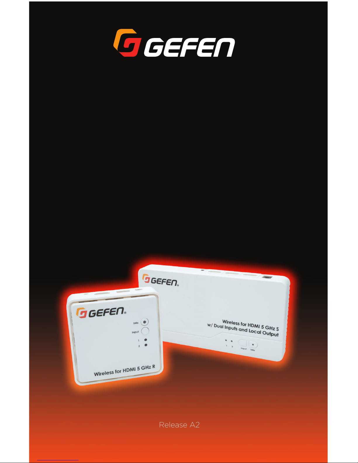
Sender Unit
®
Wireless for HDMI 5 GHz S
w/ Dual Inputs and Local Output
Input1 2 Info
®
Wireless for HDMI 5 GHz S
w/ Dual Inputs and Local Output
Input1 2 Info
DC 5V
IR OUT
SERVICE
HDMI 1 HDMI 2 HDMI OUT
®
Wireless for HDMI 5 GHz S
w/ Dual Inputs and Local Output
Input1 2 Info
DC 5V
IR OUT
SERVICE
HDMI 1 HDMI 2 HDMI OUT
Input1 2 Info
Introduction
Getting Started
Getting Started
2 31
7
9
4 5 6 8
Page 13
page | 3
Page Title
ID Name Description
1 1, 2 These LED indicators will glow solid blue to
indicate the currently selected input.
2 Input Press and release this button to select the
desired input.
3 Info Press this button to display the info screen
on the connected display. The LED indicator
indicates the current state of the Sender unit.
See LED Indicator Messages (page 37) for
more information on LED messages.
4 DC 5V Connect the included power supply from
available AC outlet to this power connector.
5 HDMI 1, HDMI 2 Connect the included HDMI cables from each
HD source to these HDMI inputs.
6 HDMI Out Connect an HDMI cable from this connector
to a local HD display. The local display
allows monitoring of the HD source at the
Sender unit.
®
Wireless for HDMI 5 GHz S
w/ Dual Inputs and Local Output
Input1 2 Info
DC 5V
IR OUT
SERVICE
HDMI 1 HDMI 2 HDMI OUT
Input1 2 Info
Introduction
Getting Started
10
Page 14

page | 4
Page Title
ID Name Description
7 IR Out Connect the included IR emitter array from
this jack to the HD sources to control the
source from the viewing location.
8 SERVICE This mini-B USB port is used for rmware
upgrades using Gefen Syner-G™.
9 IR sensor This IR sensor receives signals from the
included IR remote control.
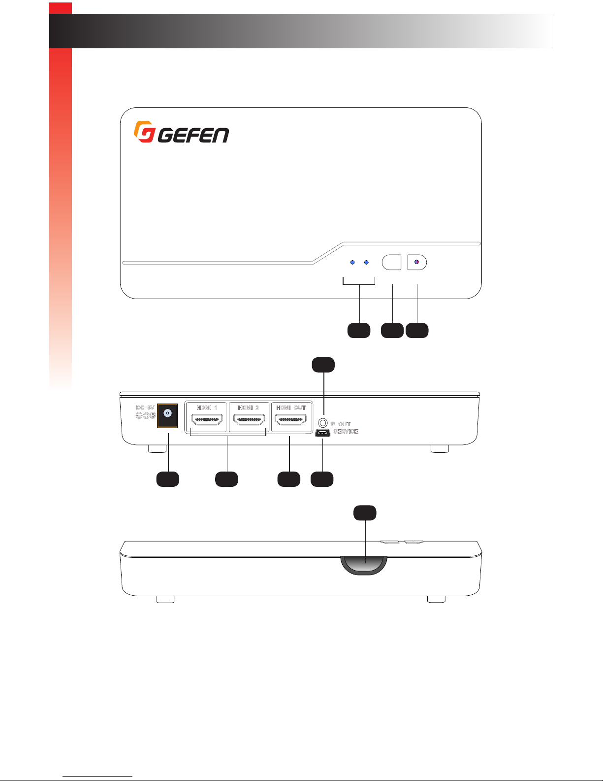
10 Tripod connector This 1/4” 20-thread hole can be used to
connect the Sender unit to a camera tripod.
Introduction
Getting Started
Getting Started
Page 15
page | 5
Introduction
Getting Started
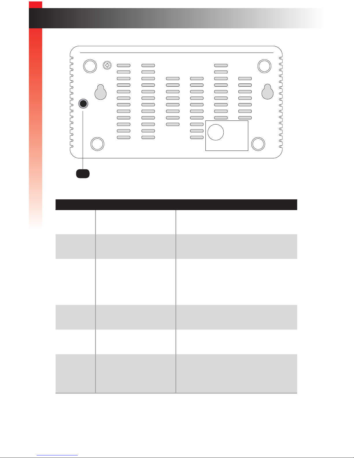
Receiver Unit
®
Input
Info
1
2
Wireless for HDMI 5 GHz R
®
Input
Info
1
2
Wireless for HDMI 5 GHz R
HDMI
IR IN
®
Input
Info
1
2
Wireless for HDMI 5 GHz R
HDMI
IR IN
1
2
3
4 5
9
6 7
8
Page 16
page | 6
Introduction
Getting Started
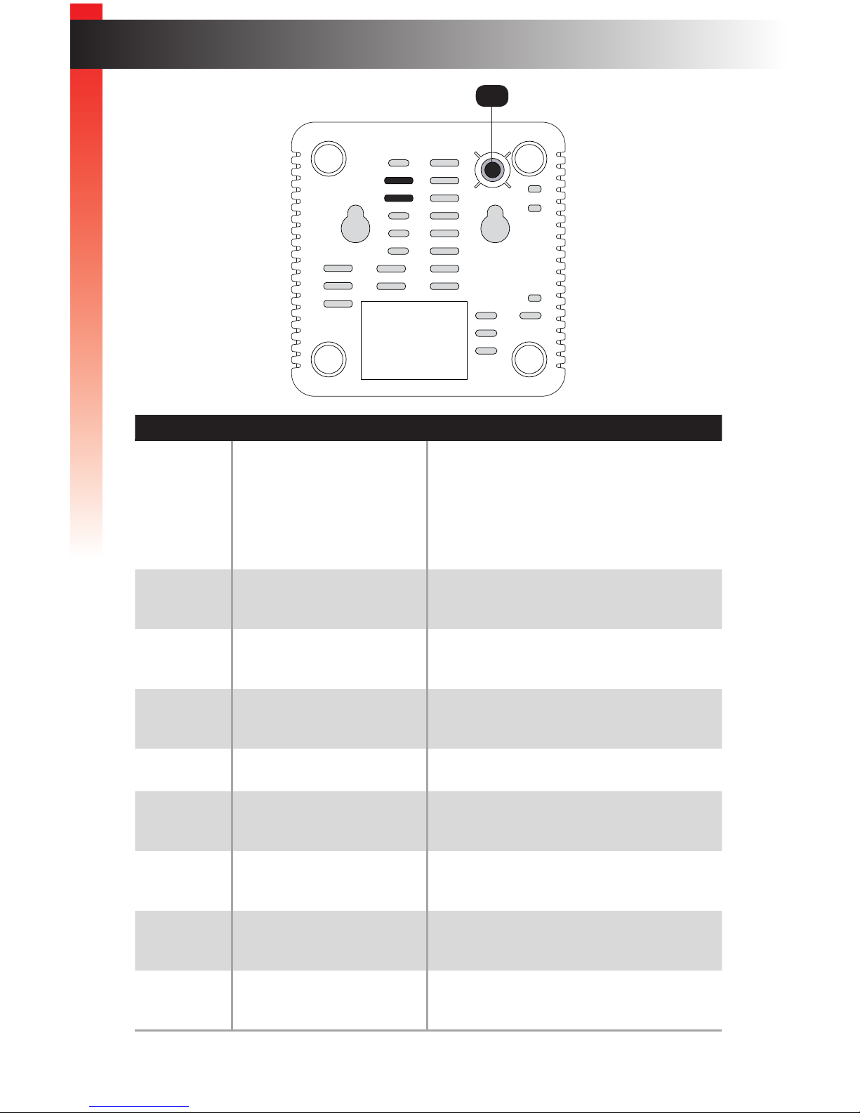
ID Name Description
1 Info Press this button to display the info screen
on the connected display. The LED
indicator indicates the current state of the
Receiver unit. See LED Indicator Messages
(page 37) for more information on LED
messages.
2 Input Press and release this button to select the
desired input.
3 1, 2 These LED indicators will glow solid blue to
indicate the selected input on the Sender unit.
4 Mini-B USB port Connect the included power supply with the
mini-B USB connector to this port.
5 USB port This port is factory use only.
6 HDMI Connect an HDMI cable from this connector
to an HD display.
7 IR In Connect the included IR Extender to this port,
if required.
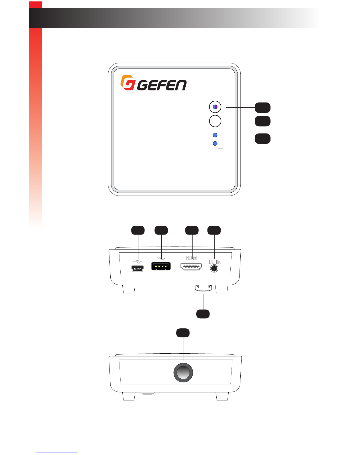
8 Tripod connector This 1/4” 20-thread hole can be used to
connect the Receiver unit to a camera tripod.
9 IR sensor This IR sensor receives IR signals. See
Connection Instructions (page 9).
®
Input
Info
1
2
Wireless for HDMI 5 GHz R
HDMI
IR IN
8
Getting Started
Page 17
page | 7
IR Remote Control
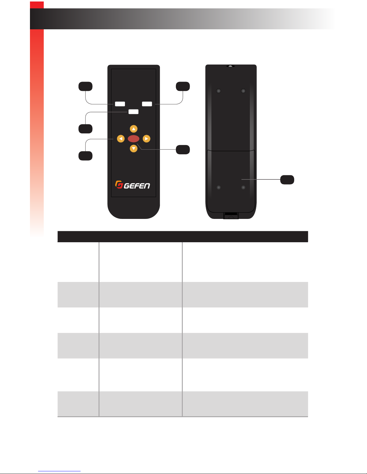
ID Name Description
1 IR Press this button to set the IR frequency
required by the source device to use the IR
emitter array. See Setting the IR Frequency
(page 20) for more information.
2 Input Press this button to select the desired input
on the active Sender unit.
3 ▲, ▼, ◄, ► Press these buttons to select the desired
option in the Information Window.
4 OK Press this button to accept the current
change within the OSD.
5 Sender Press this button to add, delete, or edit
Sender units. See Using Multiple Sender
Units (page 21) for more information.
6 Battery cover See Installing the Batteries (page 8) for
more information.
Input
RMT-WHD-1080P
OK
SenderIR
*Preferred
®
+
-
+
-
+
-
+
-
Introduction
Getting Started
6
4
1 5
2
3
Page 18

page | 8
Introduction
Getting Started
Installing the Batteries
1. Push and pull-up the tab at bottom of the IR remote to remove the battery cover.
2. Make sure that the batteries are installed with the correct polarity, as shown in the
illustration, below. Always use two 1.5V AAA-type batteries.
3. Replace the battery cover. Push the battery cover down until the tab snaps in place.
Warning!
Risk of explosion if battery is replaced by an incorrect type. Dispose of used
batteries according to the instructions.
+
-
+
-
+
-
+
-
Battery cover tab
Battery cover
Getting Started
Page 19

page | 9
Connection Instructions
► Video
1. Connect one of the included HDMI cables from the HD source to the HDMI 1 port on
the Sender unit.
2. Connect the other (included) HDMI cable from a second HD source to the
HDMI 2 port.
3. Connect an HDMI cable from the HDMI Out port on the Sender unit to a local HD
display. This display will allow monitoring of the HD source.
For best results, the local display should be identical, or have the same capabilities
as the main display in terms of resolution and features (e.g. CEC, 3D, 1080p).
► IR Control - see Sample Wiring Diagram (page 10)
4. Connect the included IR emitter array from the IR Out port on the Sender unit to the
HD sources. This will allow the sources to be controlled from the viewing location.
5. Connect the included IR Extender to the IR In port on the Receiver unit.
► Power
6. Connect the included power supplies:
• Connect the power supply with the round power connector to the Sender unit.
• Connect the power supply with the mini-B USB connector to the Receiver unit.
Installation
Getting Started
Information
Once the IR extender is connected to the Receiver unit, the IR sensor on
the Receiver unit will be disabled.
Page 20

page | 10
Sample Wiring Diagram
Getting Started
Installation
HDMI Display
at Remote
Viewing Location
IR Extender
IR Emitter
Array
EXT-WHD-1080P-LR
Receiver unit
EXT-WHD-1080P-LR
Sender unit
Local HDMI Display
HDMI Source 1
HDMI Source 2
(Up to 100 feet)
HDMI CABLE
EXT-WHD-1080P-LR
IR IN
IR OUT
Page 21

Page 22

Page 23

Wireless for HDMI 5 GHz
w/ Dual Inputs and Local Output
2 Basic Operation
Page 24

page | 14
Once the power supplies are connected, the Sender and Receiver unit(s) will begin the
linking process. During this time, the LED indicator on the Info buttons and Input LED
Indicators will ash blue for approximately 10 - 15 seconds. After this time, the source will
be shown on the display that is connected to the Receiver unit.
Figure 2.1 - Info and Input LED indicators ash blue during the linking process.
By default, HDMI 1 is selected. Therefore, the Input LED indicator for HDMI 1 will ash
along with the Info LED indicator. If HDMI 2 is selected, then the LED indicator will ash
along with the Info LED indicator. See Switching Sources (page 16) for more information
on switching sources.
Basic OperationBasic Operation
The Linking Process
®
Input
Info
1
2
Wireless for HDMI 5 GHz R
®
Wireless for HDMI 5 GHz S
w/ Dual Inputs and Local Output
Input1 2 Info
Wireless for HDMI 5 GHz S
Input1 2 Info
Input
Info
1
2
Flashing Input LED
Flashing Info LED
Basic OperationBasic Operation
Page 25

page | 15
Figure 2.2 - Info and Input LED indicators are solid blue when linked.
Basic OperationBasic Operation
®
Input
Info
1
2
Wireless for HDMI 5 GHz R
®
Wireless for HDMI 5 GHz S
w/ Dual Inputs and Local Output
Input1 2 Info
Wireless for HDMI 5 GHz S
Input1 2 Info
Input
Info
1
2
Solid Input LED
The Linking Process
HDMI1 CH1 1920x1080
An information window will be
shown, in the upper-left corner of
the display, for a few seconds after
the Sender and Receiver unit are
successfully linked. This window
can be displayed at anytime by
pressing the Info button.
See Getting Source Information
(page 18) for more information.
Solid Info LED
HDMI1 CH1 1920x1080
Page 26

page | 16
Two HD sources can be connected to a single Sender unit. Press the Input button on the
Sender or Receiver unit or on the included IR remote control to toggle between HDMI 1
and HDMI 2 input ports.
1. Make sure two sources are connected to the Sender unit.
2. Press the Input button on the Sender or Receiver unit or on the IR remote control.
In the example, both the Sender and Receiver indicate that HDMI 2 is the active input.
Basic OperationBasic Operation
Switching Sources
®
Wireless for HDMI 5 GHz S
w/ Dual Inputs and Local Output
Input1 2 Info
DC 5V
IR OUT
SERVICE
HDMI 1 HDMI 2 HDMI OUT
Input
RMT-WHD-1080P
OK
SenderIR
*Preferred
®
+
-
+
-
Sender unit
Receiver unit
Wireless for HDMI 5 GHz S
w/ Dual Inputs and Local Output
Input1 2 Info
Receiver unit
®
Input
Info
1
2
Basic OperationBasic Operation
Information
Note that before switching sources, a Sender unit must be registered with
the Receiver unit. Refer to Registering Sender Units (page 21) if you
need to pair units.
Page 27

page | 17
If the IR remote control is being used, make sure to point the remote at the IR sensor
on the Sender or Receiver unit. If using an IR extender, point the IR remote at the
sensor of the IR extender.
3. The input indicator on the Sender and Receiver unit will switch to the opposite input.
In our example, HDMI 1 is now the active input.
4. To return to switch to the other input, press the Input button again.
Wireless for HDMI 5 GHz S
w/ Dual Inputs and Local Output
Input1 2 Info
Sender unit
Receiver unit
Basic OperationBasic Operation
Switching Sources
®
Input
Info
1
2
Page 28

page | 18
Basic OperationBasic Operation
1. Make sure at least one HD source is connected to the Sender unit and the source is
connected to the active input.
2. Press the Info button on the Sender or Receiver unit.
®
Wireless for HDMI 5 GHz S
w/ Dual Inputs and Local Output
Input1 2 Info
DC 5V
IR OUT
SERVICE
HDMI 1 HDMI 2 HDMI OUT
®
Input
Info
1
2
Wireless for HDMI 5 GHz R
®
Wireless for HDMI 5 GHz S
w/ Dual Inputs and Local Output
Input1 2 Info
Wireless for HDMI 5 GHz S
Input1 2 Info
Input
Info
1
2
Info button
Getting Source Information
Basic OperationBasic Operation
Page 29

page | 19
3. Information, similar to the following, will be shown on the display connected to the
Receiver unit. Note that this information window is not displayed on the local output.
The Link icon indicates that the Receiver unit is connected to the Sender unit and is
passing A/V data. See LED Indicator Messages (page 37) for more information on
status icons.
The currently selected (active) HDMI input is indicated, along with the channel
and output resolution. The channel is automatically selected to provide the best
connection between the Sender and Receiver unit.
The icon below the Link icon indicates that the Info button can be pressed to dismiss
the information window.
4. Press the Info button to dismiss the window.
Basic OperationBasic Operation
Getting Source Information
HDMI1 CH2 1920x1080
= OFF
HDMI1 CH2 1920x1080
= OFF
Input
Link icon
Channel Resolution
Page 30

page | 20
Basic Operation
Setting the IR Frequency
The IR frequency of the Sender unit can be changed to accommodate the IR frequency of
the source device. Three frequencies are available: 38 kHz, 47 kHz, and 57 kHz.
Most sources operate on 38 kHz IR frequency, but there are some cable/satellite boxes
that require 56 kHz. In cases where the Sender unit needs to control both types of devices,
the 47 kHz frequency may deliver the best results, depending on the devices being
controlled. The IR frequency of the Sender unit can be changed to accommodate the IR
frequency of the source device. Three frequencies are available: 38 kHz, 47 kHz, and
57 kHz. See Sample Wiring Diagram (page 10) for more information on connecting the
IR emitter array.
1. Point the IR remote control at the IR sensor on Sender or Receiver unit. If using
an IR extender, point the remote at the sensor of the IR extender.
2. Press the IR button on the IR remote control. The current IR frequency will be
displayed in the information window.
3. Press and release the IR button to cycle through each of the available frequencies,
until the desired frequency is displayed.
4. The new IR frequency is now set.
5. The information window will disappear after a few seconds.
HDMI1 CH2 1920x1080
= 38KHz
IR frequency
HDMI1 CH2 1920x1080
= 47KHz
Input
RMT-WHD-1080P
OK
SenderIR
*Preferred
®
+
-
+
-
Basic Operation
Page 31

page | 21
Registering Sender Units
If purchasing additional Sender units, each Sender unit must be registered with a Receiver
unit in order for the Sender unit to communicate with the Receiver unit. Up to eight Sender
units can be registered to a Receiver unit.
In the example, below, Sender unit S1 is already registered with the Receiver unit, allowing
both Sender unit S1 and the Receiver unit to communicate. We will be adding Sender unit
S2.
1. Connect up to two HD sources to the new Sender unit, using ports HDMI 1 and
HDMI 2.
2. Point the IR remote control at the IR sensor of the Receiver unit.
3. Press the Sender button on the included IR remote control.
4. The Select Transmitter window will be displayed.
Basic Operation
Using Multiple Sender Units
®
Wireless for HDMI 5 GHz S
w/ Dual Inputs and Local Output
Input1 2 Info
DC 5V
IR OUT
SERVICE
HDMI 1 HDMI 2 HDMI OUT
Input1 2 Info
®
Wireless for HDMI 5 GHz S
w/ Dual Inputs and Local Output
Input1 2 Info
DC 5V
IR OUT
SERVICE
HDMI 1 HDMI 2 HDMI OUT
Input1 2 Info
®
Power Indicator
Info
Link
Wireless for HDMI 5 GHz R
Sender unit S1
Sender unit S2
Receiver unit
Page 32

page | 22
5. Press the ▼ button on the IR remote control to highlight the Setup option.
6. Press the OK button.
7. The Setup window will be displayed. The Add New Transmitter option will be
highlighted.
8. Press the OK button.
Basic Operation
Using Multiple Sender Units
Setup
Add New Transmitter
Remove Transmitter
Modify Transmitter Name
Return
Input
RMT-WHD-1080P
OK
SenderIR
*Preferred
®
+
-
+
-
Select Transmitter
1080PLRS
Setup
Select Transmitter
1080PLRS
Setup
Basic Operation
Page 33

page | 23
Basic Operation
Using Multiple Sender Units
9. The display will go black and the following message will be displayed as the Receiver
unit searches for additional Sender units.
10. The Info LED indicator on the Receiver unit will slowly ash bright magenta, indicating
that it is in register mode.
11. Press and hold the Info button on the new Sender unit while connecting the power
supply. Continue pressing the Info button for a few seconds until the Info LED turns
to bright magenta.
Searching.....
®
Input
Info
1
2
Wireless for HDMI 5 GHz R
Flashes magenta
®
Wireless for HDMI 5 GHz S
w/ Dual Inputs and Local Output
Input1 2 Info
Press and hold
Page 34

page | 24
12. After a few moments, the Info LED indicator on both the Receiver unit and the new
Sender unit will ash bright magenta. Both units are now in register mode.
13. Release the Info button on the Sender unit.
14. After the new Sender unit has been found, the registration process will begin:
15. To cancel the searching process, press the Sender button on the IR remote control.
You will be returned to the Select Transmitter screen:
16. If no additional Sender units are found, then the following message will be displayed.
®
Input
Info
1
2
Wireless for HDMI 5 GHz R
®
Wireless for HDMI 5 GHz S
w/ Dual Inputs and Local Output
Input1 2 Info
Basic Operation
Using Multiple Sender Units
New WHDI source was not found
Adding WHD200
Flashes magenta
Select Transmitter
1080PLRS
Setup
Basic Operation
Page 35

page | 25
The Select Transmitter screen will then be displayed.
5. Once the pairing has completed, The video from the registered Sender will be
displayed or it will go to Search mode, then you must choose between the registered
Senders in the Select Transmitter window.
Basic Operation
Using Multiple Sender Units
Select Transmitter
1080PLRS
Setup
Information
By default, the Sender unit will use HDMI 1 as the input, when connecting
to another Sender unit. If the source image is not displayed, check to
make sure a source is connected to the HDMI 1 port and that HDMI 1 is
the active input. See Switching Sources (page 16) if necessary.
®
Wireless for HDMI 5 GHz S
w/ Dual Inputs and Local Output
Input1 2 Info
DC 5V
IR OUT
SERVICE
HDMI 1 HDMI 2 HDMI OUT
Input1 2 Info
®
Wireless for HDMI 5 GHz S
w/ Dual Inputs and Local Output
Input1 2 Info
DC 5V
IR OUT
SERVICE
HDMI 1 HDMI 2 HDMI OUT
Input1 2 Info
Sender unit S1
Sender unit S2
Receiver unit
®
Power Indicator
Info
Link
Wireless for HDMI 5 GHz R
Page 36

page | 26
Selecting a Sender Unit
Use this feature to switch between multiple Sender units. To switch between source
devices on the active Sender unit, see Switching Sources (page 16).
1. Point the IR remote control at IR sensor (or the IR extender) of the Receiver unit.
2. Press the Sender button on the IR remote control.
3. The list of available Sender units will be displayed within the Select Transmitter
window.
4. Press the ▼ and ▲ buttons to highlight the desired Sender unit.
5. Press the OK button.
6. The display will go blank.
Basic Operation
Using Multiple Sender Units
Select Transmitter
1080PLRS
1080PLRS2
Setup
Select Transmitter
1080PLRS
1080PLRS2
Setup
Input
RMT-WHD-1080P
OK
SenderIR
*Preferred
®
+
-
+
-
Basic Operation
Page 37

page | 27
Basic Operation
Using Multiple Sender Units
7. After about 10 seconds, the image from the source device on the selected Sender
unit will appear on the display.
Page 38

page | 28
Basic Operation
Using Multiple Sender Units
Changing the Name of a Sender Unit
This feature allows the default name of a Sender unit, in the list, to be modied.
1. Point the IR remote control at IR sensor (or the IR extender) of the Receiver unit.
2. Press the Sender button.
3. The list of available Sender units will be displayed within the Select Transmitter
window.
4. Press the ▼ button on the IR remote control to highlight the Setup option.
Input
RMT-WHD-1080P
OK
SenderIR
*Preferred
®
+
-
+
-
Select Transmitter
1080PLRS
1080PLRS2
Setup
Select Transmitter
1080PLRS
1080PLRS2
Setup
Basic Operation
Page 39

page | 29
Basic Operation
Using Multiple Sender Units
5. Press the OK button.
6. The Setup window will be displayed. The Add New Transmitter option will be
highlighted.
7. Press the ▼ button on the IR remote control to highlight the Modify Transmitter
Name option.
8. Press the OK button.
9. The first item in this list will be highlighted. Use the ▲ or ▼ buttons to highlight
the desired Sender unit to be edited.
Setup
Add New Transmitter
Remove Transmitter
Modify Transmitter Name
Return
Edit Registered Transmitter Name
1080PLRS
1080PLRS2
Return
Page 40

page | 30
Basic Operation
Using Multiple Sender Units
10. Press the OK button.
11. The Edit transmitter name window will be displayed.
12. The rst character in the name will be highlighted with a cursor, as shown below.
► Use the ◄ or ► buttons to move the cursor forward and backward within the name.
► Press the IR button to erase the current character. When the character is
erased, the remaining characters will be shifted to the left as shown:
► Use the ▲ or ▼ button to select the desired character. The maximum length for
the Sender unit description is 16 characters.
Table 1.1 - Available characters for naming Sender units. The character in the
upper-left corner of the table is a [SPACE] character.
0 1 2 3 4 5 6 7 8 9 a b c d
e f g h i j k l m n o p q r s
t u v w x y z A B C D E F G H
I J K L M N O P Q R S T U V W
X Y Z
13. Once the desired name has been entered, press the OK button to accept the change.
14. Press the Sender button to immediately dismiss the window. If the Sender button
is not pressed, then the window will automatically be dismissed within 10 seconds.
Rebooting the Sender unit is not required.
Edit transmitter name
1080PLRS
IR = Delete
_
1080PLRS
_
080PLRS
_
Basic Operation
Page 41

page | 31
Removing Sender Units
When a Sender unit is removed (unregistered), it will be removed from the Receiver unit
and will no longer be recognized.
1. Point the IR remote control at IR sensor (or the IR extender) of the Receiver unit.
2. Press the Sender button on the IR remote control.
3. The Select Transmitter window will be displayed.
4. Press the ▼ button on the IR remote control to highlight the Setup option.
5. Press the OK button.
6. The Setup window will be displayed. The Add New Transmitter option will be
highlighted.
Input
RMT-WHD-1080P
OK
SenderIR
*Preferred
®
+
-
+
-
Basic Operation
Using Multiple Sender Units
Select Transmitter
1080PLRS
1080PLRS2
Setup
Select Transmitter
1080PLRS
1080PLRS2
Setup
Page 42

page | 32
7. Press the ▼ button on the IR remote control to highlight the Remove Transmitter
option.
8. Press the OK button.
9. The Remove Registered Transmitter window will be displayed.
10. The first item in this list will be highlighted. Use the ▲ or ▼ buttons to highlight
the desired Sender unit to be removed.
Basic Operation
Using Multiple Sender Units
Setup
Add New Transmitter
Remove Transmitter
Modify Transmitter Name
Return
Remove Registered Transmitter
1080PLRS
1080PLRS2
Return
Setup
Add New Transmitter
Remove Transmitter
Modify Transmitter Name
Return
Remove Registered Transmitter
1080PLRS
1080PLRS2
Return
Basic Operation
Page 43

page | 33
11. Press the OK button.
12. The selected Sender unit will be removed from the list.
13. Once the Sender has been removed, select the Sender to be used. See Selecting a
Sender Unit (page 26) for more information.
Note that if the only remaining Sender unit is removed from the list, then at least one
Sender unit must be added to the list. See Registering Sender Units (page 21) for
more information.
Basic Operation
Using Multiple Sender Units
Removing 1080PLRS2
Page 44

Page 45

Wireless for HDMI 5 GHz
w/ Dual Inputs and Local Output
3 Appendix
Page 46

page | 36
The Sender and Receiver unit can be mounted to any at surface, using the included wall
anchors and screws.
1. Drill two pilot holes for the Sender and Receiver unit, using the following measurements.
2. Insert the suppled wall anchors into the holes.
3. Insert the screws into each wall anchor. Make sure to leave at least 1/8” for mounting
the Sender and Receiver unit.
4. Place the Sender and Receiver unit behind the head of each screw and slide to lock in
place.
Appendix
Surface-mounting Instructions
5.5 in.
1.8 in.
5.5 in.
Appendix
Page 47

page | 37
The LED indicators on the Sender and Receiver unit provides basic information on the current
state of the Wireless for HDMI 5 GHz w/ Dual Inputs and Local Output.
Table 3.1 - Sender unit LED indicator messages
Status Description
Info LED is off
• No power supplied to the Sender
unit. Make sure the power supply is
connected to the Sender unit.
Info LED is solid blue
• Power supplied to the Sender unit.
• Sender unit is linked to Receiver unit.
Info LED is ashing blue
• Link mode. In this mode,
the Sender unit is attempting to link
with the Receiver unit. The Sender
unit must be registered by the
Receiver unit.
Info LED is ashing magenta
• Register mode. In this mode,
the Sender unit is being registered by
the Receiver unit. Once registered,
the Sender unit will appear in a list
that is stored in the Receiver unit.
See Registering Sender Units (page
21) for more information.
Input LED 1 is solid blue
• HDMI 1 is the active input.
Input LED 2 is solid blue
• HDMI 2 is the active input.
Appendix
LED Indicator Messages
Input
Info
Wireless for HDMI 5 GHz S
Input
1 2
Info
Wireless for HDMI 5 GHz S
Input
1 2
Info
Input
Info
Input
Info
Input
Info
Page 48

page | 38
Table 3.2 - Receiver unit LED indicator messages
Status Description
Info LED is off
• No power supplied to the Receiver
unit. Make sure the power supply is
connected to the Sender unit.
Info LED is solid blue
• Power supplied to the Receiver unit.
• The Receiver unit is linked to the
Sender unit.
Info LED is ashing blue
• Link mode. In this mode,
the Receiver unit is attempting to
link with Sender unit that is already
registered by the system.
Info LED is ashing magenta
• Register mode. In this mode,
the Receiver unit is attempting to
register a Sender unit that has not
been registered by the Receiver unit.
When a Sender unit is registered,
it will appear in a list that is stored in
the Receiver unit. See Registering
Sender Units (page 21) for more
information.
Input LED 1 is solid blue
• HDMI 1 is the active input on the
Sender unit.
Input LED 2 is solid blue
• HDMI 2 is the active input on the
Sender unit.
Appendix
Input
Info
Input
Info
Input
Info
Input
Info
LED Indicators
Input
Info
1
2
Input
Info
1
2
Appendix
Page 49

page | 39
Appendix
Icon Messages
The following table lists the icon messages that are used and their meaning.
Table 3.3 - Icon messages
Message Description
Initial power-up
• This icon is displayed when the
Sender and Receiver unit are both
powered and attempting to link with
one another.
Searching available channels
• These two icons will ash, alternately.
No input from selected source.
• These two icons will ash, alternately.
• Make sure the source is powered
and connected to the active HDMI
input.
Video format not recognized
• These two icons will ash, alternately.
• Check the resolution and timing of
the input (source) signal.
• See Supported Resolutions (page
40) for a list of compatible video
formats.
Page 50

page | 40
Appendix
Supported Resolutions
The following table lists all available resolutions and timings that are supported by the Wireless
for HDMI 5 GHz w/ Dual Inputs and Local Output. VESA timings are only supported when
using DVI.
Table 3.4 - Supported SD, HD, and VESA timings
Resolution Timings
480p • 640 x 480 @ 59.94 / 60 Hz
• 720 x 480 @ 59.94 Hz
• 720 x 480 @ 60 Hz
576p • 720 x 576 @ 50 Hz
720p • 1280 x 720 @ 50 Hz
• 1280 x 720 @ 59.94 / 60 Hz
1080i • 1920 x 1080 @ 50 Hz
• 1920 x 1080 @ 59.95 / 60 Hz
1080p • 1920 x 1080 @ 50 Hz
• 1920 x 1080 @ 59.94 / 60 Hz
• 1920 x 1080 @ 23.98 / 24 Hz
• 1920 x 1080 @ 25 Hz
• 1920 x 1080 @ 29.97 / 30 Hz
VGA • 640 x 480 @ 59.94 / 72.809 Hz
SVGA • 800 x 600 @ 60.317 / 72.188 Hz
XGA • 1024 x 768 @ 60 / 70.069 Hz
WXGA • 1280 x 768 @ 60 Hz
SXGA • 1280 x 1024 @ 60 Hz
Table 3.5 - Supported 3D formats and timings
Format Timings
Top-bottom • 1280 x 720p @ 50 Hz
• 1280 x 720p @ 59.94 / 60 Hz
• 1920 x 1080p @ 23.98 / 24 Hz
Frame packing • 1280 x 720p @ 50 Hz
• 1280 x 720p @ 59.94 / 60 Hz
• 1920 x 1080p @ 23.98 / 24 Hz
Side-by-side • 1920 x 1080i @ 50 Hz
• 1920 x 1080i @ 59.94 / 60 Hz
Appendix
Page 51

page | 41
Specications
Appendix
Supported Formats
Resolutions (max.) • 1080p Full HD
Connectors, Controls, and Indicators
HDMI 1 (Sender) • 1 x HDMI Type A 19-pin, female
HDMI 2 (Sender) • 1 x HDMI Type A 19-pin, female
HDMI Out (Sender) • 1 x HDMI Type A 19-pin, female
HDMI (Receiver) • 1 x HDMI Type A 19-pin, female
Power Connector (Sender) • 1 x 3.5mm barrel-type
Power Connector (Receiver) • 1 x USB Mini-B
IR Out (Sender) • 1 x 2.5mm mini-mono
IR In (Receiver) • 1 x 2.5mm mini-stereo
USB Connector (Receiver) • 1 x USB Type-A (not used)
Service (Sender) • 1 x USB Mini-B
Tripod Connector (Sender / Receiver) • 1 x 1/4” 20-thread
Input button (Sender / Receiver) • 1 x tact-type
Info button (Sender / Receiver) • 1 x tact-type
Input Indicator 1 (Sender / Receiver) • 1 x LED, blue
Input Indicator 2 (Sender / Receiver) • 1 x LED, blue
Info Indicator (Sender / Receiver) • 1 x LED, multi-color (blue / magenta)
Operational
Maximum Senders per Receiver • 8
Channel frequencies (US)
(maximum four Receivers)
• 5.19 GHz
• 5.230 GHz
• 5.755 GHz
• 5.795 GHz
Channel frequencies (EU)
(maximum two Receivers)
• 5.19 GHz
• 5.230 GHz
Power Input • 5V / 2A DC
Power consumption (Sender) • 7W (max.)
Power consumption (Receiver) • 6W (max.)
Operating Temperature • +32 to +104 ºF (0 to +40 ºC)
Operating Humidity • +10 to +85%, RH (non-condensing)
Storage Temperature • +14 to +140 ºF (-10 to +60 ºC)
Storage Humidity • +5 to +90%, RH (non-condensing)
Page 52

page | 42
Appendix
Physical
Dimensions (W x H x D) • 7.2” x 1.3” x 3.9”
(182mm x 33mm x 98mm) (Sender)
• 3.8 x 1.4” x 3.8”
(95mm x 35mm x 95mm) (Receiver)
Unit Weight • 0.5 lbs (0.25 kg) (Sender)
• 0.3 lbs (0.15 kg) (Receiver)
Shipping Weight • 2.6 lbs (1.2 kg) (EXT-WHD-1080P-LR)
• 1.5 lbs (0.65 kg) (EXT-WHD-1080P-LR-
TX)
Specications
Appendix
Page 53

page | 43
Appendix
Index
C
Connection Instructions 9
F
FCC Statement iii
Features vi
G
Getting source information 18
I
Installation 9
IR Remote Control 7
Battery cover 7
Cursor, buttons 7
Input, button 7
Installing the Batteries 8
IR, button 7
OK, button 7
Sender, button 7
L
Link mode 38
M
Messages
Icon 39
LED Indicator 37
Multiple Sender Units
registering sender units 21
Removing Sender Units 31
Renaming a Sender Unit 28
Selecting a Sender Unit 26
using 21
O
Operating Notes v
P
Packing List vii
R
Receiver Unit 5
HDMI, port 5
Info, button 5
Input, button 5
Input, indicators 5
IR In, port 5
IR sensor 5
Mini-B USB, port 5
Tripod connector 5
Tripod connectpr 6
USB A, port 5
Registering Sender Units 21
Register mode 24, 37, 38
S
Safety Instructions ii
Sender Unit 2
HDMI 1, port 2
HDMI 2, port 2
HDMI Out, port 2
Info button 2
Input button 2
Input, indicators 2
IR Out, port 2
IR sensor 2
Service, port 2
Tripod connector 3
Setting the IR frequency 20
Specications 41
Supported Resolutions 40
Surface-mounting Instructions 36
Switching sources 16
T
Table of Contents viii
Technical Support iv
W
Wiring Diagram 10
Page 54

20600 Nordhoff St., Chatsworth CA 91311
1-800-545-6900 818-772-9100 fax: 818-772-9120
www.gefen.com support@gefen.com
Stretch it. Switch it. Split it. Gefen’s got it. ®
20600 Nordhoff St., Chatsworth CA 91311
1-800-545-6900 818-772-9100 fax: 818-772-9120
www.gefen.com support@gefen.com
*Preferred
 Loading...