

Gefen EXT-UHD600A-44 User Manual

*Preferred
4x4 Matrix
4K ULTRA
w/HDR and Audio De-Embedder
EXT-UHD600A-44
User Manual
Version A1

Important Safety Instructions
1. Read these instructions.
2. Keep these instructions.
3. Heed all warnings.
4. Follow all instructions.
5. Do not use this product near water.
6. Clean only with a dry cloth.
7. Do not block any ventilation openings. Install in accordance with the manufacturer’s
instructions.
8. Do not install or place this product near any heat sources such as radiators, heat
registers, stoves, or other apparatus (including ampliers) that produce heat.
9. Do not defeat the safety purpose of the polarized or grounding-type plug. A polarized
plug has two blades with one wider than the other. A grounding type plug has two
blades and a third grounding prong. The wide blade or the third prong are provided for
your safety. If the provided plug does not t into your outlet, consult an electrician for
replacement of the obsolete outlet.
10. Protect the power cord from being walked on or pinched particularly at plugs,
convenience receptacles, and the point where they exit from the apparatus.
11. Only use attachments/accessories specied by the manufacturer.
12. To reduce the risk of electric shock and/or damage to this product, never handle or
touch this unit or power cord if your hands are wet or damp. Do not expose this
product to rain or moisture.
13. Unplug this apparatus during lightning storms or when unused for long periods of time.
14. Refer all servicing to qualied service personnel. Servicing is required when the
apparatus has been damaged in any way, such as power-supply cord or plug is
damaged, liquid has been spilled or objects have fallen into the apparatus,
the apparatus has been exposed to rain or moisture, does not operate normally,
or has been dropped.
15. Batteries that may be included with this product and/or accessories should never be
exposed to open ame or excessive heat. Always dispose of used batteries
according to the instructions.
ii

Warranty Information
For the latest warranty coverage information, refer to the Warranty and Return Policy under
the Connect section of the Gefen Web site at http://www.gefen.com/connect/warranty-and-
return-policy
iii

Contacting Gefen Technical Support
Technical Support
(707) 283-5900 (800) 472-5555
8:00 AM to 5:00 PM Monday - Friday, Pacic Time
Email
support@gefen.com
Web
http://www.gefen.com
Mailing Address
Gefen
Core Brands, LLC
c/o Customer Service
1800 S McDowell Blvd
Petaluma, CA 94954 USA
iviv

Operating Notes
• The information in this manual has been carefully checked and is believed to be
accurate. However, Gefen assumes no responsibility for any inaccuracies that may be
contained in this manual. In no event will Gefen be liable for direct, indirect, special,
incidental, or consequential damages resulting from any defect or omission in this
manual, even if advised of the possibility of such damages.
• The technical information contained herein regarding the features and specications is
subject to change without notice.
• For the latest warranty coverage information, refer to the Warranty and Return Policy
under the Support section of the Gefen Web site at www.gefen.com.
Important
Cable quality is critical when handling 600 MHz HDMI signals. It is highly
recommend that Gefen Locking HDMI cables, 10-foot or shorter, be used in
the installation. Gefen HDMI cables have been designed and tested to work at
600 MHz and reliably transport the full 18 Gbps throughput of HDMI 2.0.
© 2017 Core Brands, LLC. All Rights Reserved. All trademarks are the property of their respective owners.
Gefen® is a registered trademark of Core Brands, LLC.
Gefen and Core Brands, LLC reserve the right to make changes in the hardware, packaging, and any accompanying
This product uses UL-Listed power supplies
documentation without prior written notice.
v

Licensing
This product uses software that is subject to open source licenses, including one or more
of the General Public License Version 2 and Version 2.1, Lesser General Public License
Version 2.1 and Version 3, BSD, and BSD-style licenses. Distribution and use of this
product is subject to the license terms and limitations of liability provided in those licenses.
Specic license terms and Copyright Notications are provided in the source code.
For three years from date of activation of this product, any party may request, and we
will supply, for software covered by an applicable license (e.g. GPL or LGPL), a complete
machine-readable copy of the corresponding open source code on a medium customarily
used for software interchange. The following software and libraries are included with this
product and subject to their respective open source licenses:
• lwIP
• jQuery
lwIP is licenced under the BSD licence:
Copyright (c) 2001-2004 Swedish Institute of Computer Science.
All rights reserved.
Redistribution and use in source and binary forms, with or without modication,
are permitted provided that the following conditions are met:
1. Redistributions of source code must retain the above copyright notice, this list of
conditions and the following disclaimer.
2. Redistributions in binary form must reproduce the above copyright notice, this list of
conditions and the following disclaimer in the documentation and/or other materials
provided with the distribution.
3. The name of the author may not be used to endorse or promote products derived from
this software without specic prior written permission.
THIS SOFTWARE IS PROVIDED BY THE AUTHOR ``AS IS’’ AND ANY EXPRESS
OR IMPLIED WARRANTIES, INCLUDING, BUT NOT LIMITED TO, THE IMPLIED
WARRANTIES OF MERCHANTABILITY AND FITNESS FOR A PARTICULAR PURPOSE
ARE DISCLAIMED. IN NO EVENT SHALL THE AUTHOR BE LIABLE FOR ANY DIRECT,
INDIRECT, INCIDENTAL, SPECIAL, EXEMPLARY, OR CONSEQUENTIAL DAMAGES
(INCLUDING, BUT NOT LIMITED TO, PROCUREMENT OF SUBSTITUTE GOODS OR
SERVICES; LOSS OF USE, DATA, OR PROFITS; OR BUSINESS INTERRUPTION)
HOWEVER CAUSED AND ON ANY THEORY OF LIABILITY, WHETHER IN CONTRACT,
STRICT LIABILITY, OR TORT (INCLUDING NEGLIGENCE OR OTHERWISE) ARISING
IN ANY WAY OUT OF THE USE OF THIS SOFTWARE, EVEN IF ADVISED OF THE
POSSIBILITY OF SUCH DAMAGE.
vi

Features and Packing List
Features*
• Routes four 4K sources to four 4K displays
• Supports resolutions up to 4K Cinema-DCI (4096 x 2160 up to 60 Hz, 4:4:4), 4K
Ultra HD (3860 x 2160 up to 60 Hz, 4:4:4) with HDR, 1080p Full HD, and WUXGA
(1920x1200)
• Supports HDCP 2.2 and 1.4
• Supports HDR (High Dynamic Range) 10-bit Deep Color at 4K 60 Hz 4:2:0 and 4K 24
Hz 4:4:4
• Supports 12-bit Deep Color at 1080p Full HD (60 Hz 4:4:4) and Dolby Vision 12-bit
Deep Color; Rec. 2020 color space support - Pass through
• 3DTV pass-through
• Lip Sync pass-through
• EDID Management for rapid integration of source and displays
• Supports uncompressed LPCM digital audio up to 7.1 channels
• Supports up to 7.1 channels of HBR (High Bit Rate) digital audio including Dolby
Atmos®, Dolby® TrueHD, DTS:X™, and DTS-HD Master Audio™
• Supports the use of DVI sources and DVI displays up to 1080p Full HD and WUXGA
(1920x1200), with Gefen CAB-DVI2-HDMI-LCK DVI-to-HDMI cables (not included)
• Built-in Audio De-Embedders break out 2 channel analog, 2 channel PCM, and up to
5.1 channels of Bitstream audio from each HDMI output, allowing the audio content to
be sent to external ampliers and music distribution systems for added impact.
• 4 independent scalers allow upscaling from 1080p to 4K on two outputs and
downscaling from 4K to 1080p on the other two, maximizing compatibility in a mixedresolution display system
• Variable and xed volume
• 2 USB power ports for use with sources requiring a USB power supply, 2 A shared
• Enhanced API facilitates added functionality with third-party control systems.
• Long Reach Power (LRP) provides 500 mA at 5V on pin 18 of HDMI outputs 1 and 2.
Enables select extender devices to be powered through their HDMI input port
• Locking power connector
• Push button controls
• RS-232 Serial control interface for use with a third-party controller
• IP control via Telnet, UDP, and the built-in web server interface
• IR remote control
• Gefen Syner-G™ software simplies initial IP conguration and EDID Management
• Field-updatable rmware via web server interface
• 1 U tall enclosure, rack ears included
• Can be placed on a shelf or mounted in a standard 19-inch wide rack
* Features and specications are subject to change without notice.
vii

Features and Packing List
Packing List
The Ultra HD 600 MHz 4x4 Matrix w/ HDR and Audio De-Embedder ships with the items
listed below. If any of these items are not present in the box when you rst open it,
immediately contact your reseller or Gefen.
• 1 x 4K Ultra HD 600 MHz 4x4 Matrix
• 1 x 24V DC Power Supply (EXT-PS24U-O-6)
• 1 x AC Power Cord
• 2 x Rack Ears
• 4 x Machine screws for Rack Ears
• 4 x Self-Adhesive Rubber-Feet
• 1 x IR Extender (EXT-RMT-EXTIRN)
• 1 x IR Remote (RMT-44A)
• 1 x Quick-Start Guide
viii

Table of Contents
1 Getting Started
Introduction............................................................................................................ 2
Front Panel .................................................................................................... 2
Rear Panel .................................................................................................... 3
IR Remote Control ........................................................................................ 4
Installing the Batteries ................................................................................... 6
Setting the IR Channel .................................................................................. 7
Installation ............................................................................................................. 8
Connection Instructions ................................................................................. 8
Application Diagram ...................................................................................... 9
Network Conguration using Syner-G ......................................................... 10
2 Basic Operation
Using the IR Extender ......................................................................................... 14
Viewing the Routing Status ................................................................................. 15
Routing Inputs to Outputs.................................................................................... 16
Using the Front Panel ................................................................................. 16
Using the IR Remote Control ...................................................................... 17
Masking / Unmasking Outputs ............................................................................ 18
Locking / Unlocking the Matrix ............................................................................ 19
Routing Presets ................................................................................................... 20
Volume Control .................................................................................................... 21
Increasing / Decreasing Volume ................................................................. 21
Muting / Unmuting Audio ............................................................................. 23
The Web Interface ............................................................................................... 24
Introduction to the Web Interface ................................................................ 24
Locking the Matrix ....................................................................................... 29
Viewing the Routing Status ......................................................................... 30
Routing Inputs and Masking Outputs .......................................................... 31
Routing Presets ........................................................................................... 34
Input and Output Status .............................................................................. 37
Changing Input and Output Names ............................................................. 38
Video ........................................................................................................... 39
Audio ........................................................................................................... 40
HPD Control ................................................................................................ 41
HDCP .......................................................................................................... 42
Setting the EDID Mode ............................................................................... 44
Copying EDID Data ..................................................................................... 46
Getting EDID Information ............................................................................ 48
Uploading and Downloading EDID Data ..................................................... 49
Conguring Network Settings ...................................................................... 52
System Settings .......................................................................................... 58
ix

3 Advanced Operation
Using Telnet, UDP, and RS-232 .......................................................................... 68
Telnet Conguration .................................................................................... 68
UDP Conguration ...................................................................................... 68
RS-232 Conguration .................................................................................. 69
Commands .......................................................................................................... 70
Discovery Service ....................................................................................... 70
Input Status ................................................................................................. 70
Manage EDID .............................................................................................. 70
Network Settings ......................................................................................... 71
Output Status .............................................................................................. 72
Presets ........................................................................................................ 72
Routing ........................................................................................................ 72
Setup ........................................................................................................... 73
System Settings .......................................................................................... 73
Volume ........................................................................................................ 73
4 Appendix
Network Cable Diagram .................................................................................... 168
Default Settings ................................................................................................. 169
Internal EDID Proles ........................................................................................ 170
Specications .................................................................................................... 175
Table of Contents
x

This page left intentionally blank.

This page left intentionally blank.

4x4 Matrix
4K ULTRA
w/HDR and Audio De-Embedder
1 Getting Started
Introduction
Page Title
Front Panel
51 3 4
Getting Started
1 2 3 4 Off 1 2 3 4 Off 1 2 3 4 Off 1 2 3 4 Off
A B C
D
Ultra HD 600 MHz 4x4 Matrix w/HDR and Audio De-Embedder
4K 60 Hz 4:4:4, HDMI 2.0, HDCP 2.2
Reset Power
2
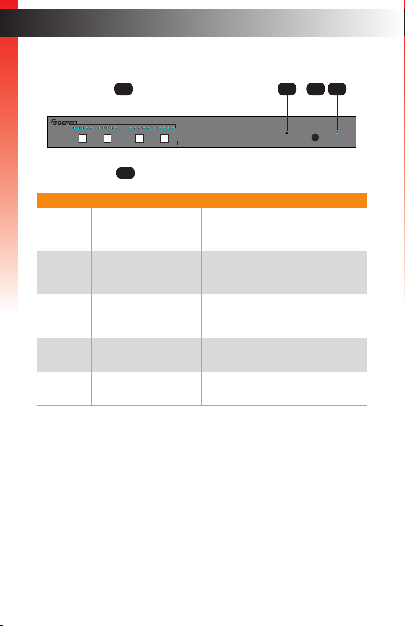
ID Name Description
1 Input indicators These blue LED indicators display the state
2 Output Selection Buttons
(A - D)
3 Reset Press and hold this button for 10 seconds
4 IR This IR sensor receives signals from the
5 Power This LED will glow bright blue when the
of each input. See Routing Inputs to Outputs
(page 16) for more information.
Press these buttons to select the desired
output. See Routing Inputs to Outputs (page
16) for more information.
and relaese to reset the matrix to factorydefault settings.
included IR remote control unit.
matrix is powered.
page | 2
Introduction
Ultra HD 600 MHz 4x4 Matrix w/HDR and Audio De-Embedder
4K 60 Hz 4:4:4, HDMI 2.0, HDCP 2.2
1 2 3 4 Off 1 2 3 4 Off 1 2 3 4 Off 1 2 3 4 Off
A B C
D
Reset Power
Rear Panel
1 4 7
Page Title
Getting Started
EXT-UHD600A-44
IR In/Ext
L/R L/R L/R
Out A
DS US DS US
Out B Out C
LRP
L/R
Out D
Out DOut COut BOut AIn 4In 3In 2In 1
RS-232
2 3 5 6 8
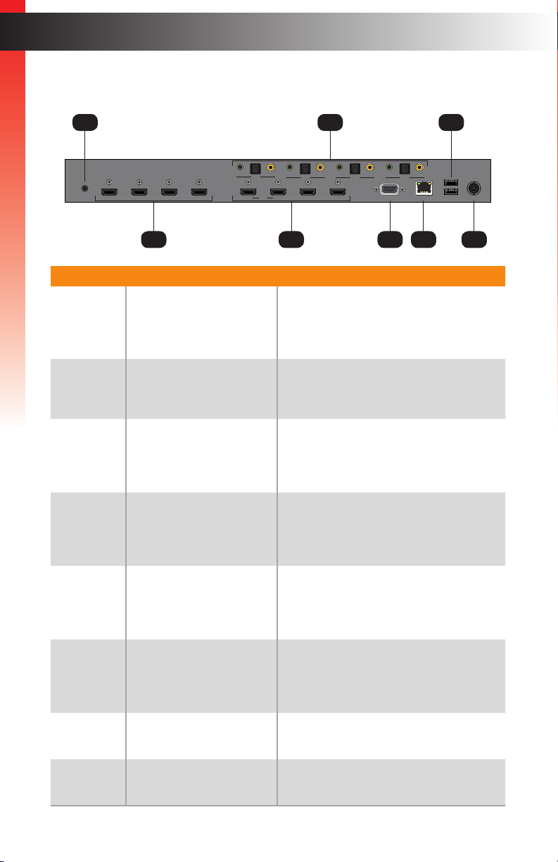
ID Name Description
1 IR In / Ext Connect an IR extender (Gefen part no.
2 In (1 - 4) Connect up to four 4K Ultra HD source
3 Out (A - D) Connect up to four 4K Ultra HD displays
4 Audio outputs Each HDMI output provides a three separate
EXT-RMT-EXTIRN) or an electrical IR
cable from an automation system to this
port.
devices to the matrix using these HDMI
ports.
to the matrix using these HDMI ports. See
Connection Instructions (page 8) for more
information.
ports for audio de-embedding: 1) L/R
(analog), 2) coax (digital), 3) TOSLINK®
(digital).
IP Control
USB Power
USB
USB
24V DC
5 RS-232 Connect the RS-232 cable from this port
to an RS-232 device. See Connection
Instructions (page 8) for more
information.
6 IP Control Connect an Ethernet cable between
this jack and a LAN. See Connection
Instructions (page 8) for more
information.
7 USB Power Connect up to two USB-powered devices.
Combined maximum current output is 2A.
8 24V DC Connect the included 24V DC power supply
to this power connector.
page | 3
IR Remote Control
R03,1.5V
R03,1.5V
ON
1 2
Introduction
Getting Started
1
A B
C D
Output
Mute
Volume
Mask
Up
Preset
8
7
6
5
2
Lock
Down
OFF1
Input
2
3
4
RMT-44A
3
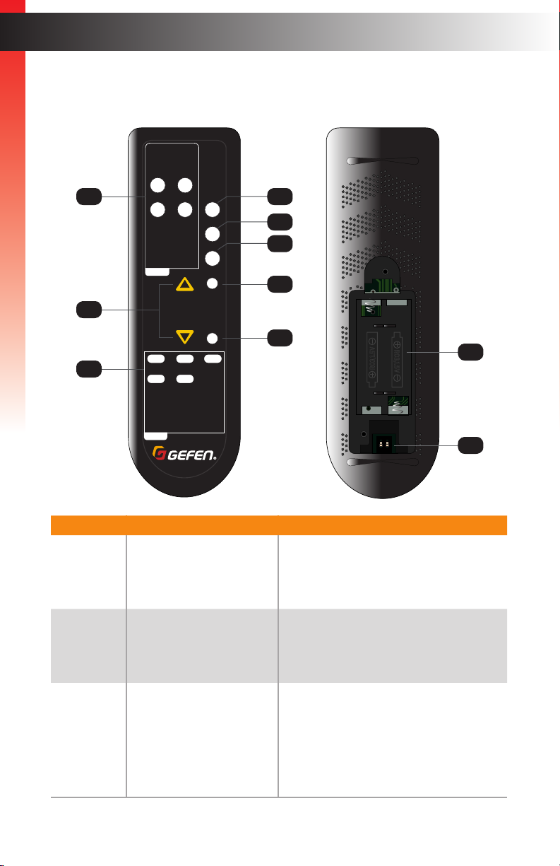
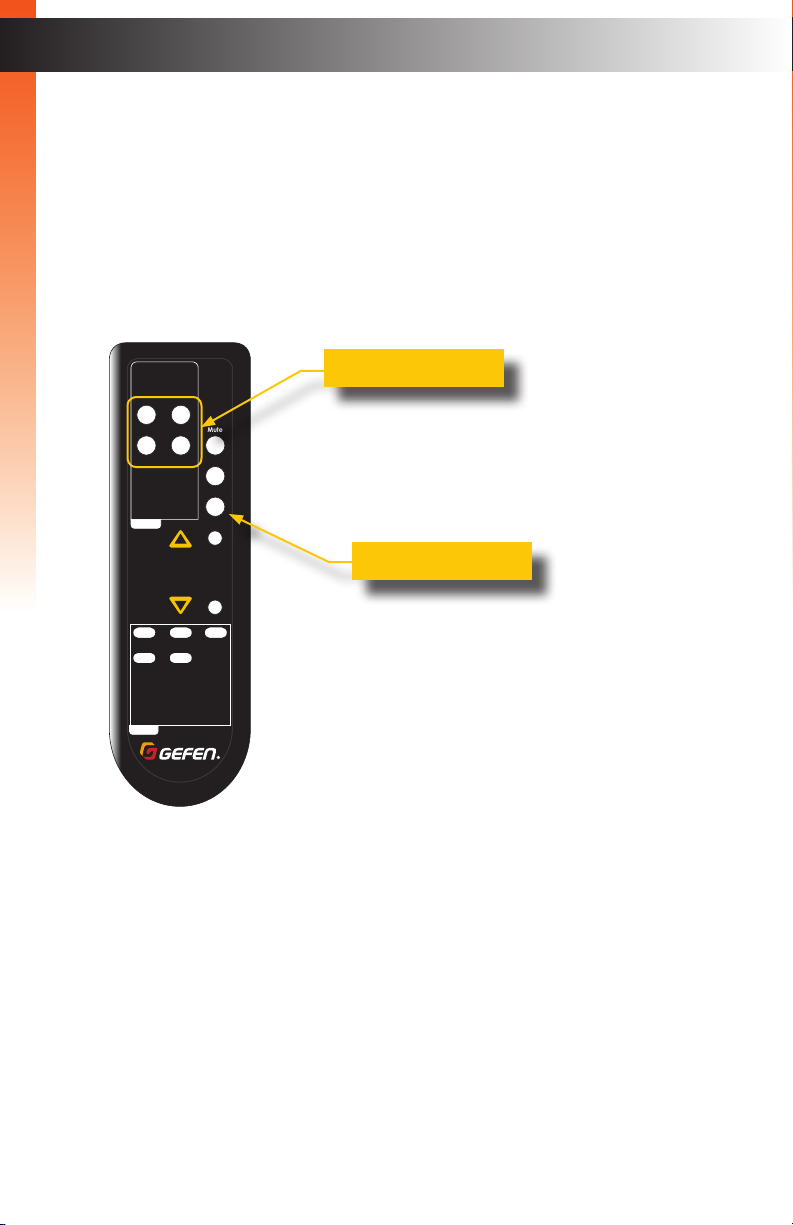
ID Name Description
1 Output buttons (A - D) Press these buttons to select the desired
4
R03,1.5V
R03,1.5V
ON
1 2
input when performing routing operations.
Each button corresponds to an Out port
(A - D) on the rear panel of the matrix.
10
9
2 ▲, ▼ Press these buttons to increase or
decrease the output volume. See
Increasing / Decreasing Volume (page
21) for more information.
3 Input buttons (1 - 4) Press these buttons to select the desired
input when performing routing operations.
Each button corresponds to an In port
(1 - 4) on the rear panel of the matrix.
Press the Off button to set the input to the
Off state, to simulate a source that is not
connected.
page | 4

ID Name Description
4 Lock Press this button to toggle between locking
Getting Started
5 Preset Press this button to select the desired
and unlocking the buttons on the front
panel.
preset. See Routing Presets (page 20)
for more information.
Introduction
6 Mask Press this button to mask the desired
7 Volume Adjusts the output volume on the selected
8 Mute Press this button to mute all audio. See
9 DIP switches Sets the IR channel of the IR remote
10 Battery compartment
(shown open)
output. See Masking / Unmasking Outputs
(page 18) for more information.
output. See Increasing / Decreasing
Volume (page 21) for more information.
Muting / Unmuting Audio (page 23) for
more information.
control. In order for the IR remote control
to communicate with the matrix, both the IR
remote control and the matrix must be set
to the same IR channel. See Setting the
IR Channel (page 7) for setting the IR
channel of the IR remote control. Use Web
GUI to set the IR channel of the matrix.
See System Settings (page 73) for more
information.
Accepts two 1.5V AAA-type batteries. See
Installing the Batteries (page 6) for
more information.
page | 5
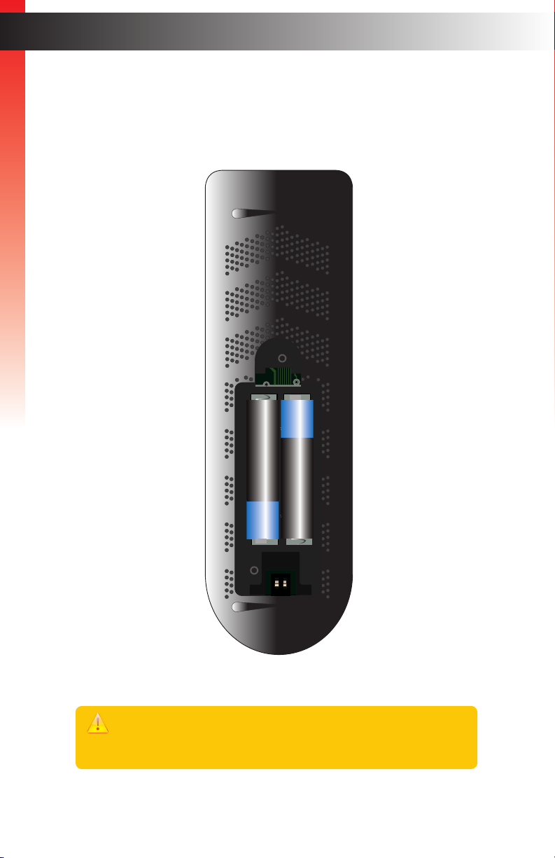
Installing the Batteries
1. Remove the back cover the IR remote control unit.
2. Insert two 1.5V AAA-type batteries, as shown, within the battery compartment.
Getting Started
+
_
R03,1.5V
R03,1.5V
_
+
ON
1 2
Introduction
3. Replace the back cover.
Warning!
Risk of explosion if battery is replaced by an incorrect type. Dispose of used
batteries according to the instructions.
page | 6
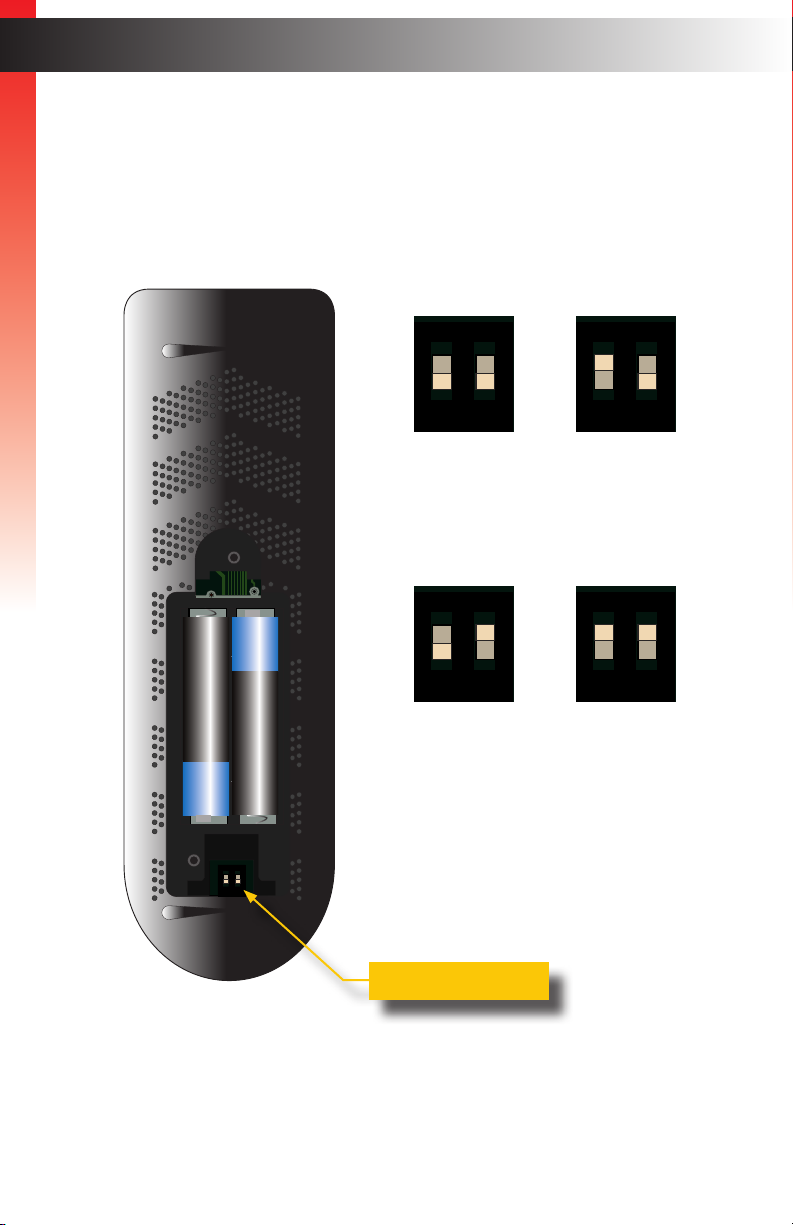
Setting the IR Channel
R03,1.5V
R03,1.5V
R03,1.5V
R03,1.5V
Use the following DIP switch settings to set the IR channel of the IR remote control.
In order for the included IR remote control to communicate with the matrix, the IR remote
control must be set to the same channel as the matrix.
Getting Started
Introduction
Channel 1 (default):
ON
1 2
DIP1 = OFF
DIP2 = OFF
Channel 3: Channel 4:
ON
+
_
R03,1.5V
R03,1.5V
_
+
ON
1 2
1 2
DIP1 = OFF
DIP2 = ON
Channel 2:
ON
1 2
DIP1 = ON
DIP2 = OFF
ON
1 2
DIP1 = ON
DIP2 = ON
DIP switches
page | 7

Installation
Connection Instructions
► Video
1. Connect an HDMI cable from each 4K Ultra HD source device to the In ports
Getting Started
(1 - 4) on the rear panel of the matrix. Up to four source devices can be
connected.
2. Connect a 4K Ultra HD display to each of the Out ports (A - D) on the rear panel
of the matrix. Up to four displays can be connected. Use the ports marked “DS” to
allow for optional down-scaling of the source signal. Use the “US” ports to provide
optional up-scaling capability.
► Audio De-embedding
3. The matrix provides one analog and two digital outputs for each HDMI output for audio
de-embedding:
a. Connect a 3.5mm mini-stereo cable from each L/R port to an A/V receiver.
b. Connect a RCA cable from each coax port to an A/V receiver.
c. Connect an optical cable from each TOSLINK® port to an A/V receiver.
► IP Control
4. Connect a shielded CAT-5e (or better) cable from the IP Control port on the rear panel
of the matrix to the Local Area Network. See Network Conguration using Syner-G
(page 10) for more information on conguration.
► RS-232 (optional)
5. Connect a DB-9 cable from the RS-232 port on the rear panel of the matrix to the
automation device. See RS-232 Conguration (page 69) for more information.
► IR Control (Optional)
6. Connect an IR extender (Gefen part no. EXT-RMT-EXTIRN) or an electrical IR cable
from an automation system to the IR In / Ext port on the rear panel of the matrix.
Connecting an IR extender is useful if the IR sensor on the front panel will be hidden
from view.
► Power
7. Connect the included 24V DC power supply to the power connector on the matrix.
8. Connect the AC power cord to the power supply and connect the power cord
to an available electrical outlet.
page | 8
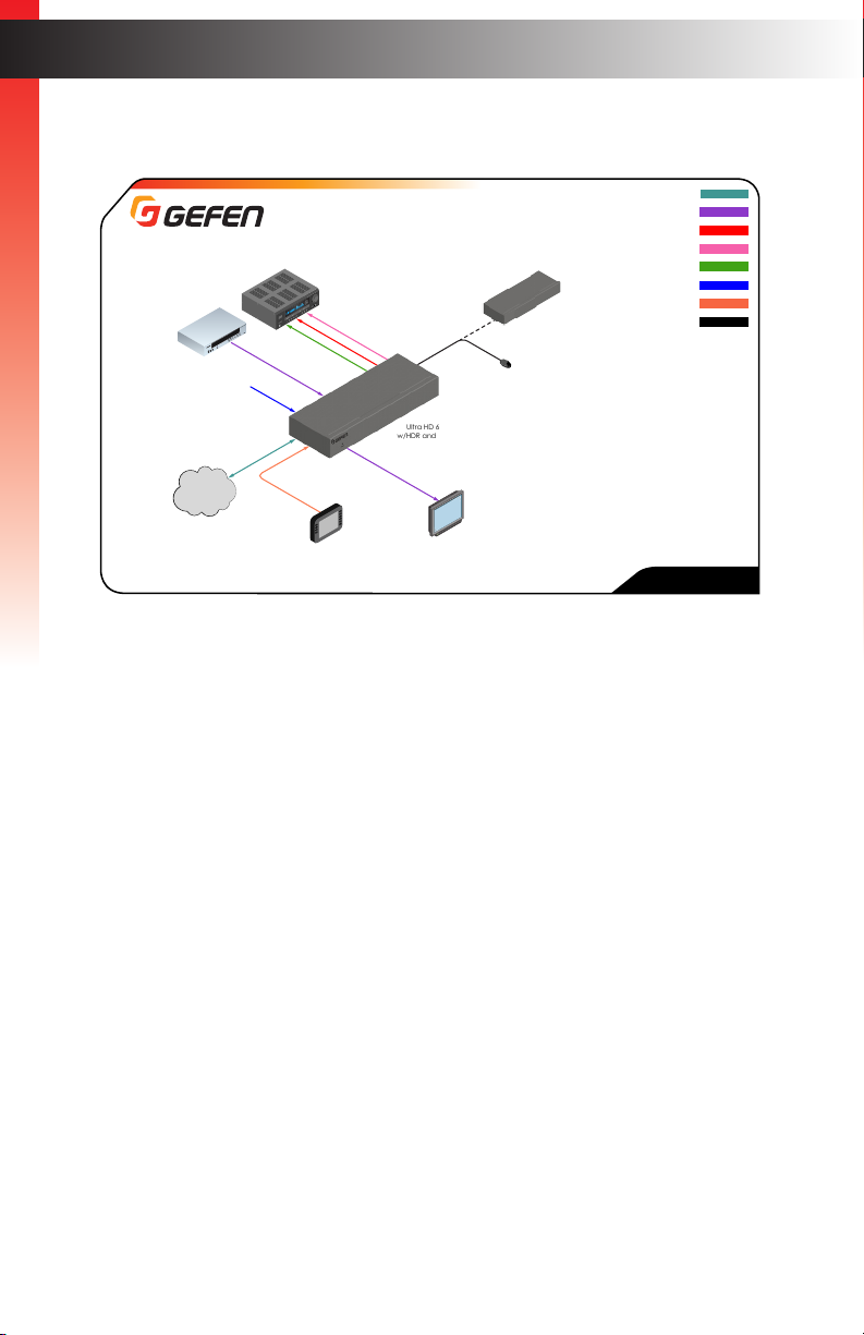
Getting Started
4x
4K Ultra HD
Sources
(Web Interface,
Telnet, or UDP)
2x
Power Source for
Streaming Sources
LAN
Application Diagram
4x
Power Amplifier
4x
De-Embeddeed Audio
Automation
Controller
with RS-232 Interface
Ultra HD 600 MHz 4x4 Matrix
w/HDR and Audio De-Embedder
OR
4x
4K Ultra HD
Displays
DIGITAL AUDIO ( TOSLINK®)
DIGITAL AUDIO (COAX)
ANALOG AUDIO (L/R)
EXT-RMT-EXTIRN
IR Extender
Automation
Controller
with IR Out
RS-232
EXT-UHD600A-44
Installation
CAT -5
HDMI
USB
IR IN
page | 9
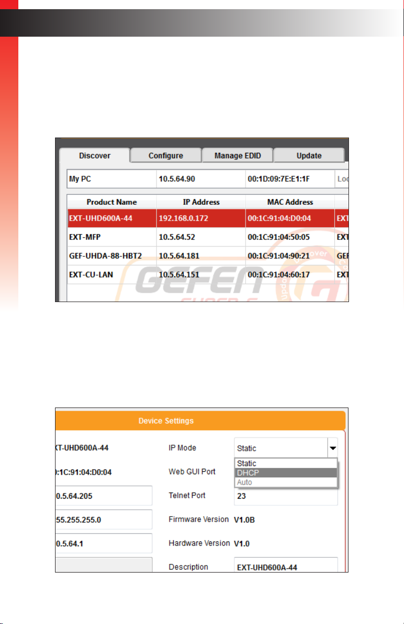
Network Configuration using Syner-G
1. Launch the Gefen Syner-G application.
Download the application here: http://www.gefen.com/support/download.jsp
Getting Started
2. Select the matrix (EXT-UHD600A-44) from the list of products.
Installation
3. Under the Device Settings section, select either Static or DHCP from the IP Mode
drop-down list.
► Select Static to manual enter the IP address, subnet mask, and gateway IP.
Consult with your network administrator, if necessary.
► Select DHCP to let the DHCP server automatically assign the IP address, subnet
mask, and gateway IP.
page | 10
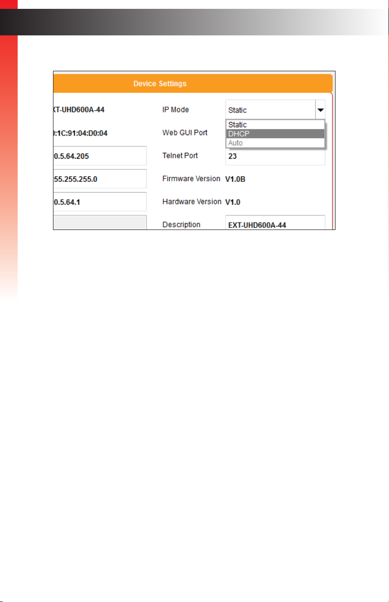
4. Click the Save button at the bottom of the screen.
Getting Started
5. The matrix will automatically reboot and use the new network settings.
6. Use the IP address of the matrix to access the built-in web interface or start a Telnet
session. See the following for more information:
► The Web Interface (page 24)
Installation
► Using Telnet, UDP, and RS-232 (page 68)
page | 11

This page left intentionally blank.

4x4 Matrix
4K ULTRA
w/HDR and Audio De-Embedder
2 Basic Operation
Using the IR Extender
R03,1.5V
R03,1.5V
ON
1 2
Ultra HD 600 MHz 4x4 Matrix w/HDR and Audio De-Embedder
4K 60 Hz 4:4:4, HDMI 2.0, HDCP 2.2
1 2 3 4 Off 1 2 3 4 Off 1 2 3 4 Off 1 2 3 4 Off
A B C
D
Reset Power
Out DOut COut B
Out B Out C
Out D
RS-232
L/R L/R
L/R
DS US
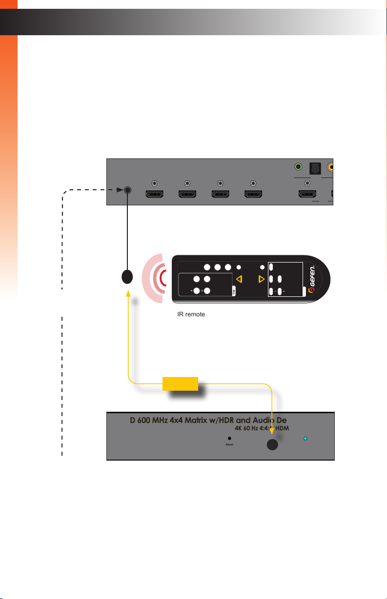
There may be situations where the IR sensor is blocked by a cabinet or other mounting
device. In this case, the included IR extender (Gefen part no. EXT-RMT-EXTIRN) can
be connected to the IR In/Ext port on the rear panel of the matrix. The sensor on the IR
extender behaves exactly like the sensor on the front panel of the matrix. Always point the
IR remote control unit in the direction of the IR sensor.
The IR In/Ext port can also receive electrical IR signals from an Automation Control
Basic OperationBasic Operation
System. Connect a 3.5mm-to-3.5mm mini-stereo cable from the IR In/Ext port to the port
on the control system.
OR
from Automation
Control System
EXT-UHD600A-44
IR In/Ext
IR extender
IR sensor
A B
IR remote
Mute
Mask
Volume
C D
Preset
Up
Output
4K 60 Hz 4:4:4, HDMI 2.0, HDCP 2.2
Reset Power
L/R
Out A
DS US
Out AIn 4In 3In 2In 1
LRP
OFF1
Lock
Down
2
4
3
RMT-44A
Input
page | 14
Viewing the Routing Status
Ultra HD 600 MHz 4x4 Matrix w/HDR and Audio De-Embedder
Ultra HD 600 MHz 4x4 Matrix w/HDR and Audio De-Embedder
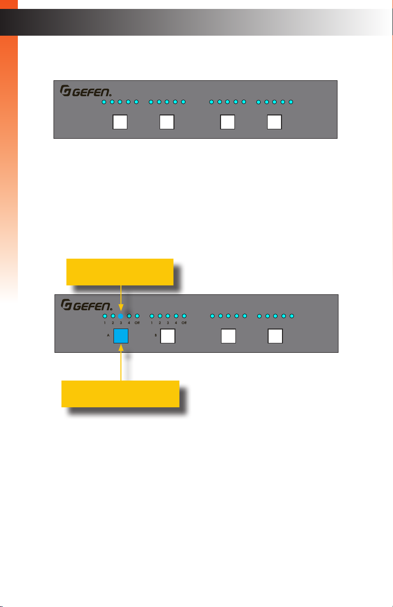
On the top-left portion of the matrix, there are four sets of ve LED indicators. Each set of
ve LED indicators resides above each of the four output buttons.
Basic OperationBasic Operation
1 2 3 4 Off 1 2 3 4 Off 1 2 3 4 Off 1 2 3 4 Off
A B C
D
LED indicators 1 through 4 represent each input on the matrix. If one of these LED
indicators are illuminated, then that means that the input is active.
The “Off” LED indicates that the output is turned off (masked). Refer to Masking /
Unmasking Outputs (page 18) for more information on masking and unmasking outputs.
Each of the output buttons are used to route inputs to outputs. When an output button is
illuminated, it represent the currently selected output. For example, in the illustration below,
Input 1 has been routed to Output A:
LED indicates that Input 3
is the active input
1 2 3 4 Off 1 2 3 4 Off 1 2 3 4 Off 1 2 3 4 Off
A B C
D
Indicates that Output A is the
currently selected output
In addition, in the above illustration, Input 2 is routed to Output B, Input 3 is routed to
Output C, and Input 4 is routed to Output D. If the number of the input is the same as the
number of the output, then this is called the “one-to-one” routing state. This is the factory-
default routing state of the matrix.
page | 15
Ultra HD 600 MHz 4x4 Matrix w/HDR and Audio De-Embedder
Ultra HD 600 MHz 4x4 Matrix w/HDR and Audio De-Embedder
Ultra HD 600 MHz 4x4 Matrix w/HDR and Audio De-Embedder
Routing Inputs to Outputs
When the matrix is shipped from the factory, the matrix is set to “one-to-one” routing
mode. This means that Input 1 is routed to Output A, Input 2 is routed to Output B,
Input 3 is routed to Output C, and so on. To change the routing state for any output,
follow the instructions below.
Basic OperationBasic Operation
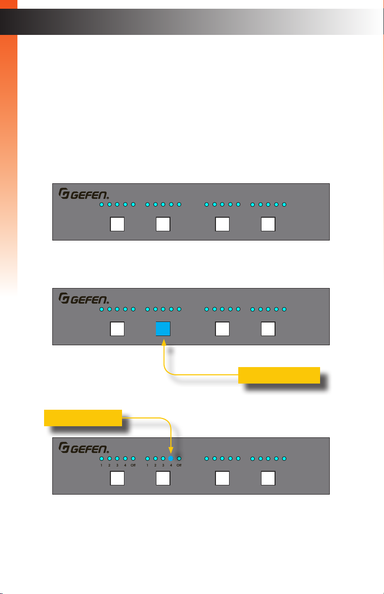
Using the Front Panel
To change the routing state of an output, press and release the button of the desired output
to advance to the next input.
In the illustration below, the source connected to Input 2 is currently routed to Output B.
For this example, we will route Input 4 to Output B.
1 2 3 4 Off 1 2 3 4 Off 1 2 3 4 Off 1 2 3 4 Off
A B C
D
1. Select output 2 by pressing button B. The LED for 2 is illuminated, indicating that
Input 2 is currently routed to Output B.
1 2 3 4 Off 1 2 3 4 Off 1 2 3 4 Off 1 2 3 4 Off
A B C
D
Output B is selected
2. Press button Output 2, twice.
Input 4 is selected
1 2 3 4 Off 1 2 3 4 Off 1 2 3 4 Off 1 2 3 4 Off
A B C
D
3. The LED indicator for Input 4 is now illuminated. This indicates that Input 4 is now
routed to Output B.
page | 16
Ultra HD 600 MHz 4x4 Matrix w/HDR and Audio De-Embedder
R03,1.5V
R03,1.5V
ON
1 2
Routing Inputs to Output
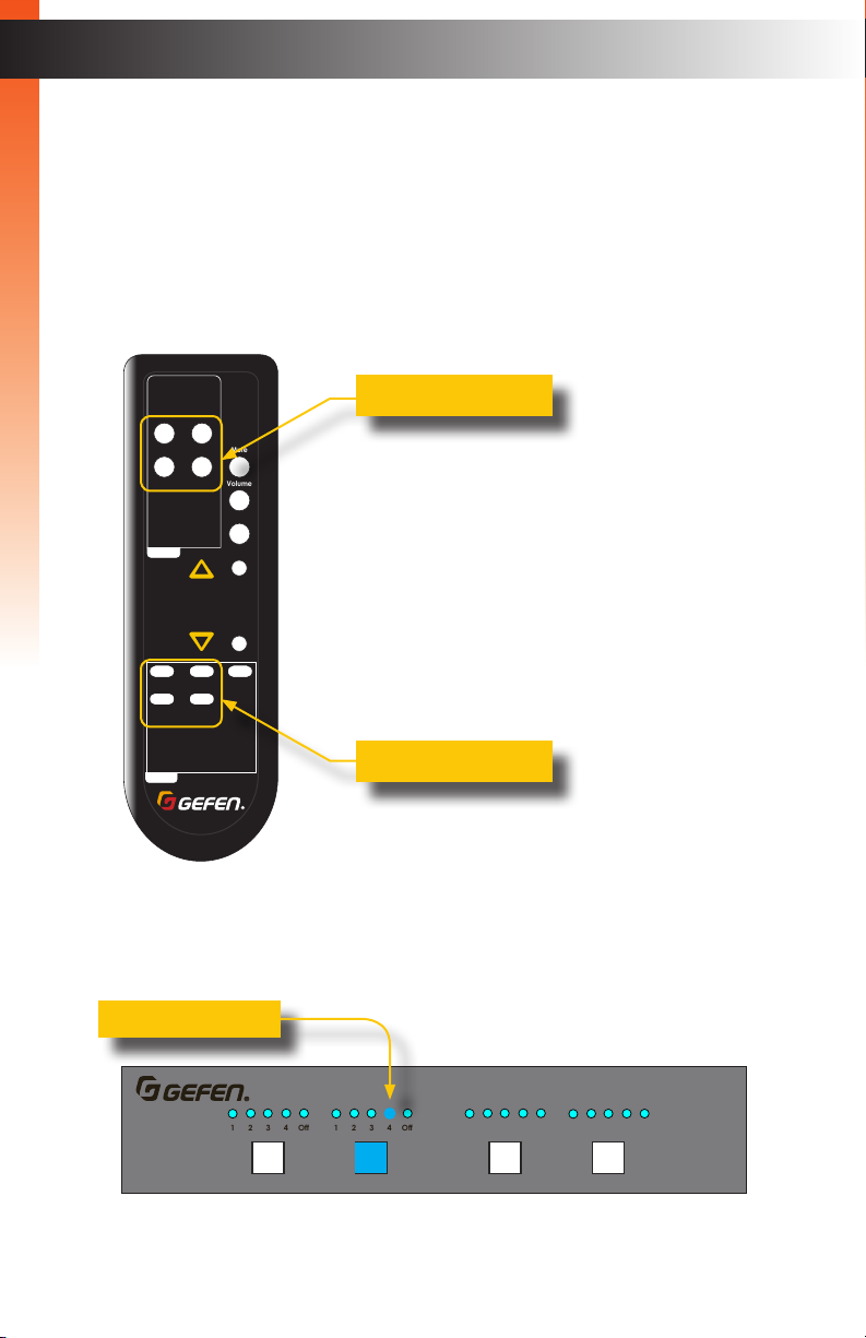
Using the IR Remote Control
In the example below, the same routing example, outlined on the previous page, is used.
1. Point the IR remote at the IR sensor on the front panel of the matrix.
Basic OperationBasic Operation
2. Select the desired input. In this example, we will select Input 4. Always select the
input before selecting the output.
A B
C D
Output
Mute
Volume
Mask
Up
Preset
3
Lock
Down
OFF1
2
4
Input
RMT-44A
Output buttons
Input buttons
3. Select the desired output. In this example, we will select Output B.
4. The LED indicator for Input 4 is now illuminated. Input 4 is now routed to Output B.
Input 4 is selected
1 2 3 4 Off 1 2 3 4 Off 1 2 3 4 Off 1 2 3 4 Off
A B C
D
page | 17
Masking / Unmasking Outputs
R03,1.5V
R03,1.5V
ON
1 2
When masking outputs through the front panel, the IR remote control must be used.
Outputs can also be masked by using the built-in web interface. See Routing Inputs and
Masking Outputs (page 31) for more information.
When an output is masked, the signal is blocked at the output. For example, if Input 2
is routed to Output A, Output B, and Output C. If Output B is masked, then only the A/V
signal on Output B will be blocked. Output A and Output C will remain unaffected.
Basic OperationBasic Operation
1. Press the Mask button on the IR remote. This will cause all the output buttons (A, B,
C, D), on the front panel of the matrix, to start ashing.
A B
C D
Output
Mute
Volume
Mask
Up
Preset
3
Lock
Down
OFF1
2
4
Input
RMT-44A
Output buttons
Mask button
2. Press the desired output button on the IR remote to be masked/unmasked.
The associated output button, on the front panel of the matrix, will illuminate for
approximately one second, and then exit mask mode.
The matrix will wait approximately three seconds for a response from the IR remote.
If no mask operation takes place, or if any other button on the IR remote is pressed,
then the matrix will exit mask mode.
3. To unmask a masked output, repeat the above steps.
page | 18
 Loading...