

Page 1
4x1 Switcher for HDMI w/HDR
*Preferred
4K ULTRA
4K 60 Hz 4:4:4
HDCP 2.2 & Auto Switching
EXT-UHD600-41
User Manual
Release A2
Page 2

Important Safety Instructions
1. Read these instructions.
2. Keep these instructions.
3. Heed all warnings.
4. Follow all instructions.
5. Do not use this product near water.
6. Clean only with a dry cloth.
7. Do not block any ventilation openings. Install in accordance with the manufacturer’s
instructions.
8. Do not install or place this product near any heat sources such as radiators, heat
registers, stoves, or other apparatus (including ampliers) that produce heat.
9. Do not defeat the safety purpose of the polarized or grounding-type plug. A polarized
plug has two blades with one wider than the other. A grounding type plug has two
blades and a third grounding prong. The wide blade or the third prong are provided for
your safety. If the provided plug does not t into your outlet, consult an electrician for
replacement of the obsolete outlet.
10. Protect the power cord from being walked on or pinched particularly at plugs,
convenience receptacles, and the point where they exit from the apparatus.
11. Only use attachments/accessories specied by the manufacturer.
12. To reduce the risk of electric shock and/or damage to this product, never handle or
touch this unit or power cord if your hands are wet or damp. Do not expose this
product to rain or moisture.
13. Unplug this apparatus during lightning storms or when unused for long periods of time.
14. Refer all servicing to qualied service personnel. Servicing is required when the
apparatus has been damaged in any way, such as power-supply cord or plug is
damaged, liquid has been spilled or objects have fallen into the apparatus,
the apparatus has been exposed to rain or moisture, does not operate normally,
or has been dropped.
15. Batteries that may be included with this product and/or accessories should never be
exposed to open ame or excessive heat. Always dispose of used batteries
according to the instructions.
ii
Page 3

Warranty Information
Gefen warrants the equipment it manufactures to be free from defects in material and
workmanship.
If equipment fails because of such defects and Gefen is notied within two (2) years from
the date of shipment, Gefen will, at its option, repair or replace the equipment, provided
that the equipment has not been subjected to mechanical, electrical, or other abuse or
modications. Equipment that fails under conditions other than those covered will be
repaired at the current price of parts and labor in effect at the time of repair. Such repairs
are warranted for ninety (90) days from the day of reshipment to the Buyer.
This warranty is in lieu of all other warranties expressed or implied, including without
limitation, any implied warranty or merchantability or tness for any particular purpose, all of
which are expressly disclaimed.
1. Proof of sale may be required in order to claim warranty.
2. Customers outside the US are responsible for shipping charges to and from Gefen.
3. Copper cables are limited to a 30 day warranty and cables must be in their original
condition.
The information in this manual has been carefully checked and is believed to be accurate.
However, Gefen assumes no responsibility for any inaccuracies that may be contained
in this manual. In no event will Gefen be liable for direct, indirect, special, incidental, or
consequential damages resulting from any defect or omission in this manual, even if
advised of the possibility of such damages. The technical information contained herein
regarding the features and specications is subject to change without notice.
For the latest warranty coverage information, refer to the Warranty and Return Policy under
the Support section of the Gefen Web site at www.gefen.com.
iii
Page 4

Licensing
This product uses software that is subject to open source licenses, including one or more
of the General Public License Version 2 and Version 2.1, Lesser General Public License
Version 2.1 and Version 3, BSD, and BSD-style licenses. Distribution and use of this
product is subject to the license terms and limitations of liability provided in those licenses.
Specic license terms and Copyright Notications are provided in the source code.
For three years from date of activation of this product, any party may request, and we
will supply, for software covered by an applicable license (e.g. GPL or LGPL), a complete
machine-readable copy of the corresponding open source code on a medium customarily
used for software interchange. The following software and libraries are included with this
product and subject to their respective open source licenses:
• jQuery
• Linux
iv
Page 5

Contacting Gefen Technical Support
Technical Support
(707) 283-5900 (800) 472-5555
8:00 AM to 5:00 PM Monday - Friday, Pacic Time
Email
support@gefen.com
Web
http://www.gefen.com
Mailing Address
Gefen
Core Brands, LLC
c/o Customer Service
1800 S McDowell Blvd
Petaluma, CA 94954 USA
Product Registration
Register your product here: http://www.gefen.com/kvm/Registry/Registration.jsp
v
Page 6

Operating Notes
• The Gefen Syner-G Software Suite is a free downloadable application from Gefen
that provides a variety of useful tools, including automatic download and installation of
rmware upgrades for this product. Always make sure that this product is running the
latest rmware.
Important
Cable quality is critical when handling 600 MHz HDMI signals. It is highly
recommend that Gefen Locking HDMI cables be used in the installation.
Gefen HDMI cables have been designed and tested to work at 600 MHz
and reliably transport the full 18 Gbps throughput of HDMI 2.0.
© 2016 Core Brands, LLC. All Rights Reserved. All trademarks are the property of their respective owners.
Gefen and Core Brands LLC reserve the right to make changes in the hardware, packaging, and any accompanying
This product uses UL-Listed power supplies
documentation without prior written notice.
vi
vi
Page 7

Features and Packing List
2.2
60Hz, 4:4:4
600 MHz
4K ULTRA
Deep Color Support
4K
DCI, 4096 x 2160, 30Hz
Features
• Routes up to four Ultra Hi-Def sources to one Ultra HD display
• Supports resolutions up to 4K DCI-Cinema (4096 x 2160 at 60 Hz, 4:4:4), 4K Ultra HD
(3860 x 2160 at 60Hz, 4:4:4), 1080p Full HD, & 1920x1200 (WUXGA)
• Supports HDCP 2.2 and 1.4
• Supports HDR (High Dynamic Range) 10-bit Deep Color at 4K 60 Hz 4:2:0 and 4K 24
Hz 4:4:4
• Supports 12-bit Deep Color at 1080p 60 Hz 4:4:4
• 3DTV pass-through
• Lip Sync pass-through
• Advanced EDID and HDCP Management via Web Server Interface for rapid
integration of sources and display
• Supports uncompressed LPCM digital audio up to 7.1 channels
• Supports up to 7.1 channels of HBR (High Bit Rate) digital audio including Dolby
Atmos®, Dolby® TrueHD, DTS:X™, and DTS-HD Master Audio™
• Supports the use of DVI sources and DVI displays up to 1080p Full HD and
1920x1200 (WUXGA), with HDMI-to-DVI adapters (not included)
• Congurable Automatic Input Switching selects the most recent connected or
powered-up source
• Front Panel Push button Input Selector routes one of the 4 connected sources to the
display, or “Blocks” (turns off) the input
• RS-232 Serial interface for use with an automation control system
• IP control via Telnet, UDP, and the built-in web server interface
• IR remote control
• Small surface-mountable IR Extender module allows the switcher to be hidden away
behind the display or in the equipment closet
• Gefen Syner-G™ software’s Discovery and Show-Me features simplify initial IP
conguration
• In-eld rmware update via Web Server Interface
• Long Reach Power (LRP) provides 500 mA at 5V on pin 18 of HDMI output. Enables
select extender devices to be powered through their HDMI input port
• Locking power connector ensures reliable operation
• Low-prole, surface-mountable enclosure can be surface mounted, placed on a shelf,
or hidden away behind the display
H
D
R
High Dynamic Range
CINEMA
DCI, 4096 x 2160, 30Hz
vii
Page 8

Features and Packing List
Packing List
The Ultra HD 600 MHz 4x1 Switcher for HDMI w/ HDR ships with the items listed below.
The packing contents of the Sender and Receiver unit are listed below. If any of these
items are not present in the box when you rst open it, immediately contact your dealer or
Gefen.
• 1 x Ultra HD 600 MHz 4x1 Switcher for HDMI w/ HDR
• 1 x 5V Power Supply w US/EU/UK/AU plugs
• 1 x IR Extender Module (EXT-RMT-EXTIRN)
• 1 x Hand-held IR Remote
• 2 x Surface Mounting L-Brackets
• 4 x M3 6 mm Machine screws for mounting the L-Brackets to unit
• 2 x 6-32 5 mm Machine screws for mounting the unit to Gefen EXT-RACK-1U-GRY
(available separately)
• 4 x Self-Adhesive Rubber Feet
• 1 x Quick-Start Guide
viii
Page 9

Table of Contents
1 Getting Started
Introduction............................................................................................................ 2
Front Panel .................................................................................................... 2
Rear Panel .................................................................................................... 3
IR Remote Control ........................................................................................ 4
Installing the Batteries ................................................................................... 5
Setting the IR Channel .................................................................................. 6
Installation ............................................................................................................. 7
Connection Instructions ................................................................................. 7
Sample Application Diagram ......................................................................... 8
2 Basic Operation
Switching Inputs .................................................................................................. 12
Using the Front Panel Buttons .................................................................... 12
Using the IR Remote Control ...................................................................... 13
The Web Interface ............................................................................................... 14
Introduction to the Web Interface ................................................................ 14
Routing ........................................................................................................ 18
Input and Output Status .............................................................................. 19
Changing Input and Output Names ............................................................. 20
HPD Control ................................................................................................ 21
HDCP .......................................................................................................... 22
Icon Selection .............................................................................................. 24
Setting the EDID Mode ............................................................................... 25
Copying EDID Data ..................................................................................... 27
Getting EDID Information ............................................................................ 29
Uploading and Downloading EDID Data ..................................................... 30
Conguring Network Settings ...................................................................... 33
System Settings .......................................................................................... 39
3 Advanced Operation
Using Telnet, UDP, and RS-232 .......................................................................... 48
Telnet Conguration .................................................................................... 48
UDP Conguration ...................................................................................... 48
RS-232 Conguration .................................................................................. 49
Commands .......................................................................................................... 50
4 Appendix
Network Cable Diagram .................................................................................... 120
Specications .................................................................................................... 121
Index.................................................................................................................. 123
ixix
Page 10

This page left intentionally blank.
Page 11

4x1 Switcher for HDMI w/HDR
4K ULTRA
1 Getting Started
Page 12
Introduction
Page Title
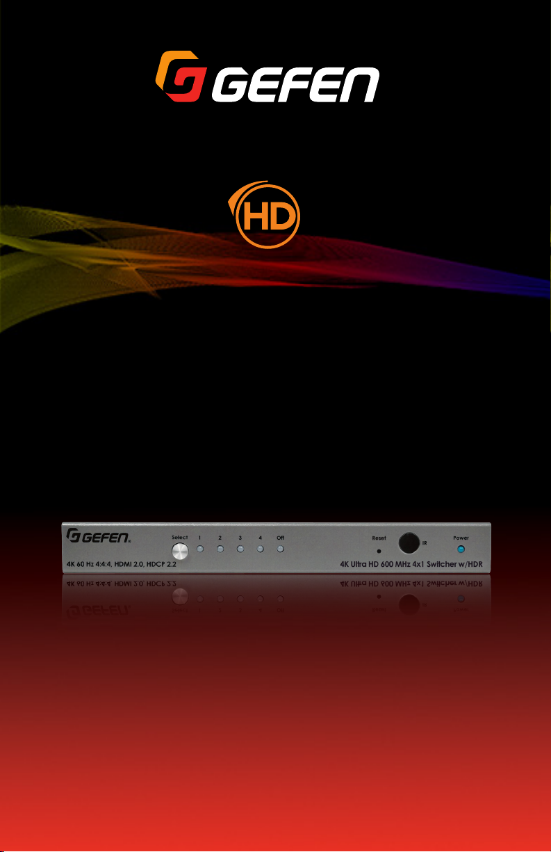
Front Panel
Getting Started
4K 60 Hz 4:4:4, HDMI 2.0, HDCP 2.2
®
ID Name Description
1 Select Press and release this button to switch
2 Input Indicators (1 - 4) Each of these LED indicators represent an
3 Off When this LED indicator is selected, it will
1 5 6
Select
1 2 3 4
Off
Reset Power
4K Ultra HD 600 MHz 4x1 Switcher w/HDR
2 3 4
between each of the inputs and the Off
indicator.
input on the rear panel of the switcher. When
an input is selected, using the Select button,
it will glow bright green. If the selected
source is not active, then the indicator will
glow amber.
glow bright green. In this state, none of the
inputs will be active.
IR
4 Reset Press and hold this button for 3 seconds to
reset the switcher to factory-default settings.
5 IR This IR sensor receives signals from the
included IR remote control unit.
6 Power This LED indicator will glow bright blue
when the included 5V DC power supply is
connected from the switcher to an available
electrical outlet.
page | 2
Page 13
Page Title
4K Ultra HD 600 MHz 4x1 Switcher w/HDR
Off
1 2 3 4
Select
®
4K 60 Hz 4:4:4, HDMI 2.0, HDCP 2.2
IR
Reset Power
Introduction
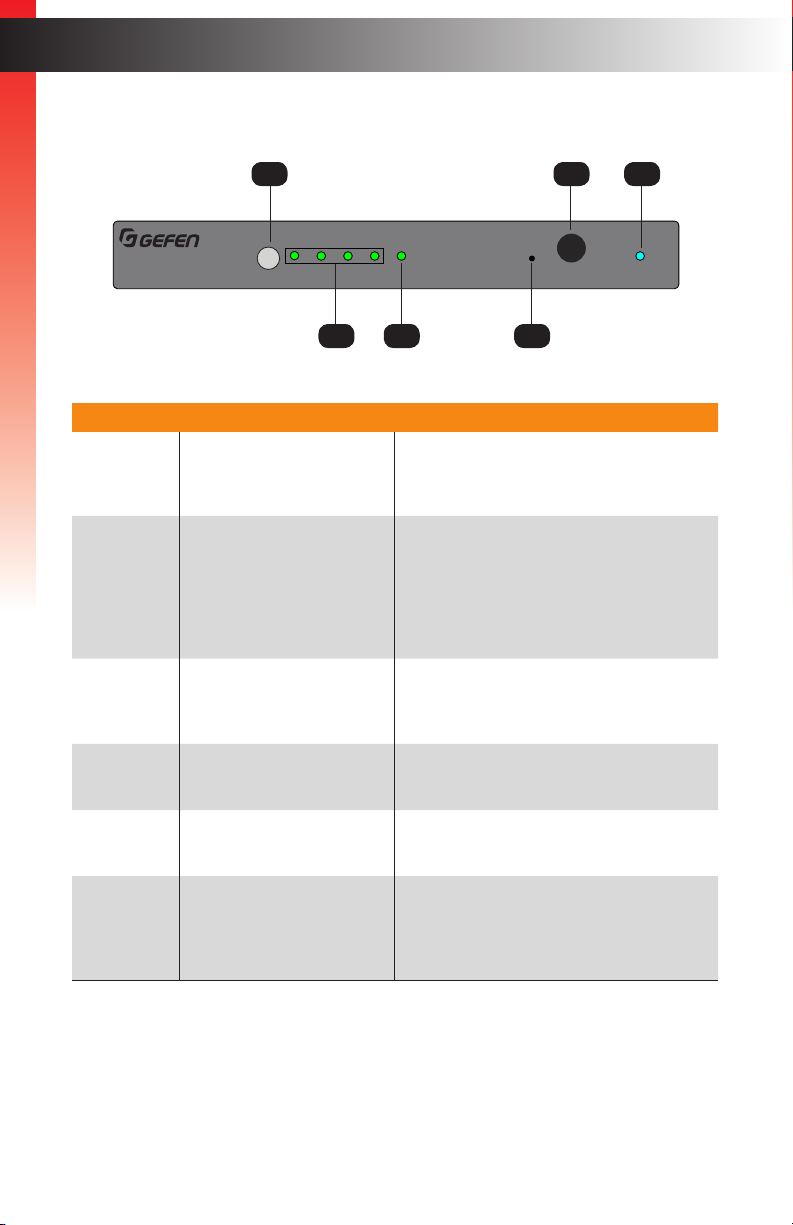
Rear Panel
Getting Started
1 3 4 5 62
EXT-UHD600-41
In 2 In 3 In 4In 1Output (LRP)IR In/Ext
ID Name Description
1 IR In/Ext Connect an IR extender (Gefen part no.
EXT-RMT-EXTIRN) or an electrical IR
cable from an automation system to this
port.
2 Output (LRP) Connect a locking HDMI cable from this
HDMI port to an Ultra HD display.
3 In 1 - In 4 Connect a locking HDMI cable from an Ultra
HD source to each of these HDMI ports.
4 RS-232 Connect an RS-232 cable from this port to
an RS-232 device. See Using Telnet,
UDP, and RS-232 (page 48) for more
information.
RS-232 IP Control
5V DC
5 IP Control Connect an Ethernet cable between
6 5V DC Connect the included locking 5V DC power
this jack and a LAN to use IP control.
See Using Telnet, UDP, and RS-232 (page
48) for more information.
supply to this power receptacle.
page | 3
Page 14
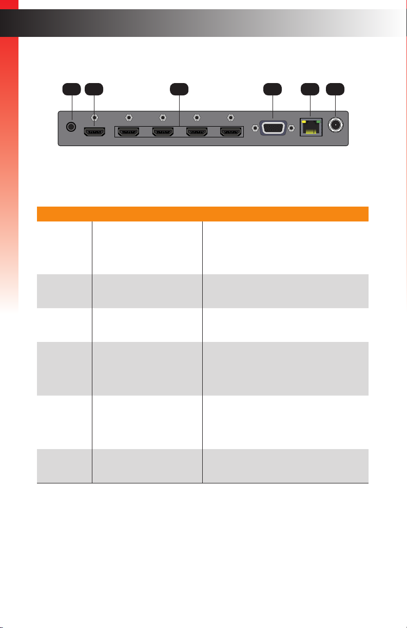
IR Remote Control
R03,1.5V
R03,1.5V
ON
1 2
*Preferred
Introduction
Getting Started
1
1
2
3
4
R03,1.5V
R03,1.5V
ON
1 2
RMT-41
®
ID Name Description
1 Input buttons (1 - 4) Press these buttons to select the desired
input when performing routing operations.
Each button corresponds to an In port
(1 - 4) on the rear panel of the switcher.
2
3
2 Battery compartment
(shown open)
Accepts two 1.5V AAA-type batteries.
See the next page for more information.
3 DIP switches Sets the IR channel of the IR remote
control. In order for the IR remote control
to communicate with the switcher, both the
IR remote control and the switcher must be
set to the same IR channel. See System
Settings (page 39) for information on
setting the IR channel of the switcher.
page | 4
Page 15
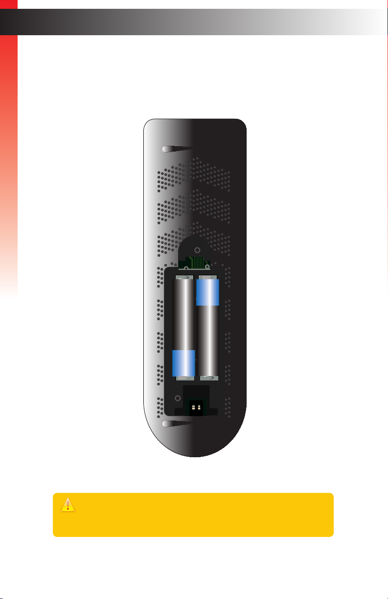
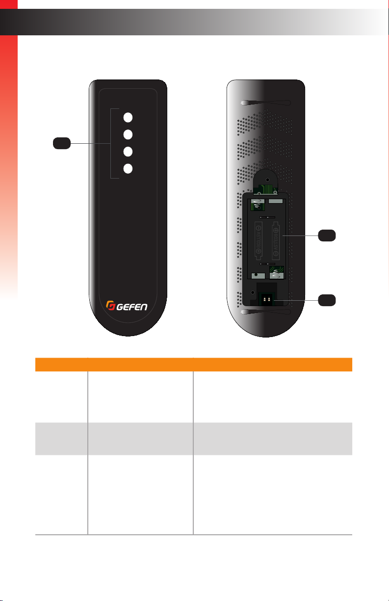
Installing the Batteries
1. Remove the back cover the IR remote control unit.
2. Insert two 1.5V AAA-type batteries, as shown, within the battery compartment.
Getting Started
+
_
R03,1.5V
R03,1.5V
_
+
ON
1 2
Introduction
3. Replace the back cover.
Warning!
Risk of explosion if battery is replaced by an incorrect type. Dispose of used
batteries according to the instructions.
page | 5
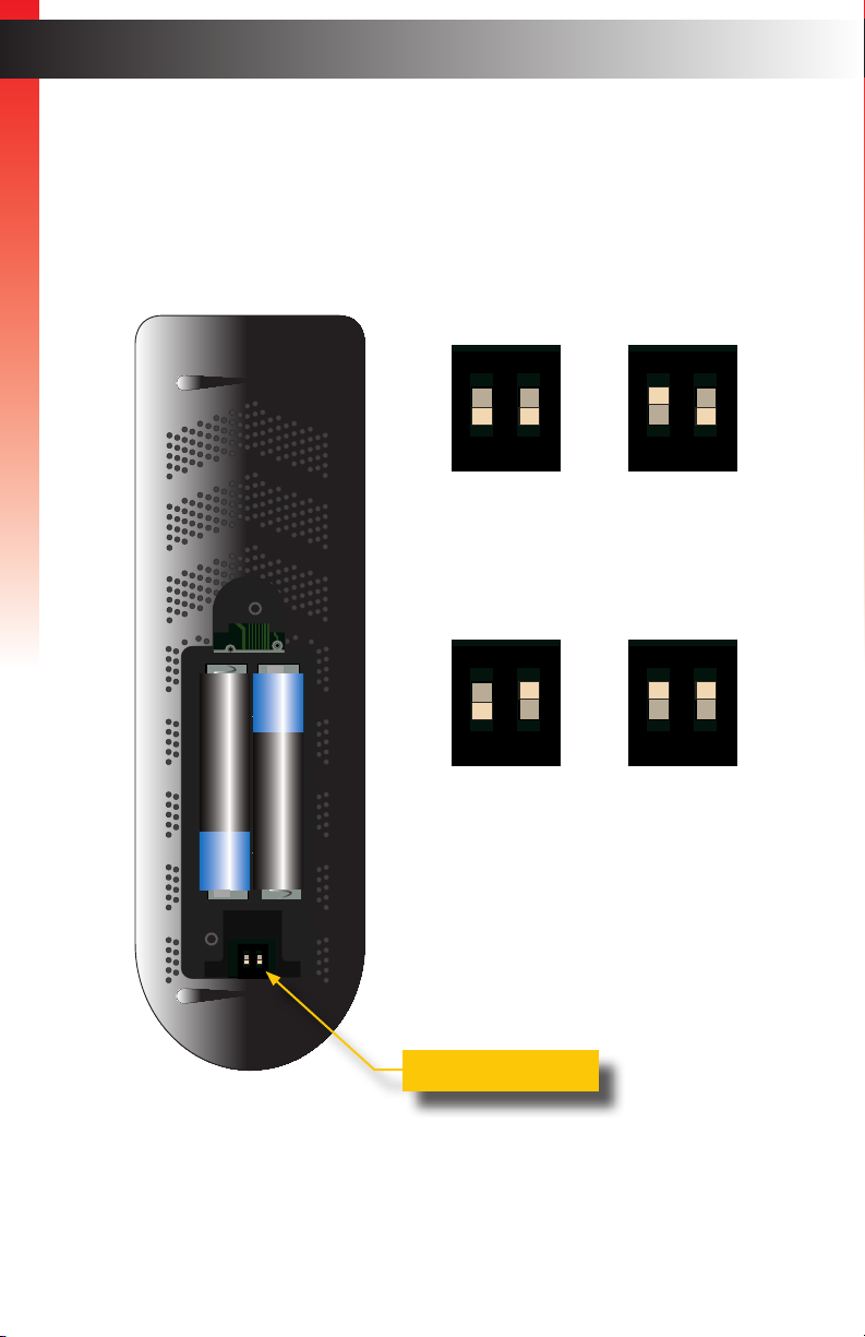
Page 16
Setting the IR Channel
R03,1.5V
R03,1.5V
R03,1.5V
R03,1.5V
Use the following DIP switch settings to set the IR channel of the IR remote control.
In order for the included IR remote control to communicate with the matrix, the IR remote
control must be set to the same channel as the matrix. See System Settings (page 39)
Getting Started
for more information.
Introduction
Channel 1 (default):
ON
1 2
DIP1 = OFF
DIP2 = OFF
Channel 3: Channel 4:
ON
+
_
R03,1.5V
R03,1.5V
_
+
ON
1 2
1 2
DIP1 = OFF
DIP2 = ON
Channel 2:
ON
1 2
DIP1 = ON
DIP2 = OFF
ON
1 2
DIP1 = ON
DIP2 = ON
DIP switches
page | 6
Page 17

Installation
Connection Instructions
► Video
1. Use an HDMI cable to connect up to four Ultra HD sources to the inputs (In 1 - In 4)
Getting Started
on the rear panel of the switcher.
2. Connect the included locking HDMI cable to the Output 1 (LRP) port on the rear panel
of the switcher. The HDMI cable can then be connected in any of the following ways:
• Connect the HDMI cable to an Ultra HD display.
• Connect the HDMI cable to another EXT-UHD600 switcher or splitter,
for cascading purposes.
Important
Cable quality is critical when handling 600 MHz HDMI signals. We highly
recommend Gefen Locking HDMI cables. They have been designed and
tested to work at 600 MHz and reliably transport the full 18 Gbps throughput
of HDMI 2.0.
► Power
3. Connect the included 5V DC locking power supply to the 5V DC power receptacle on
the rear panel of the switcher.
4. Connect the power supply to an available electrical outlet.
page | 7
Page 18
Getting Started
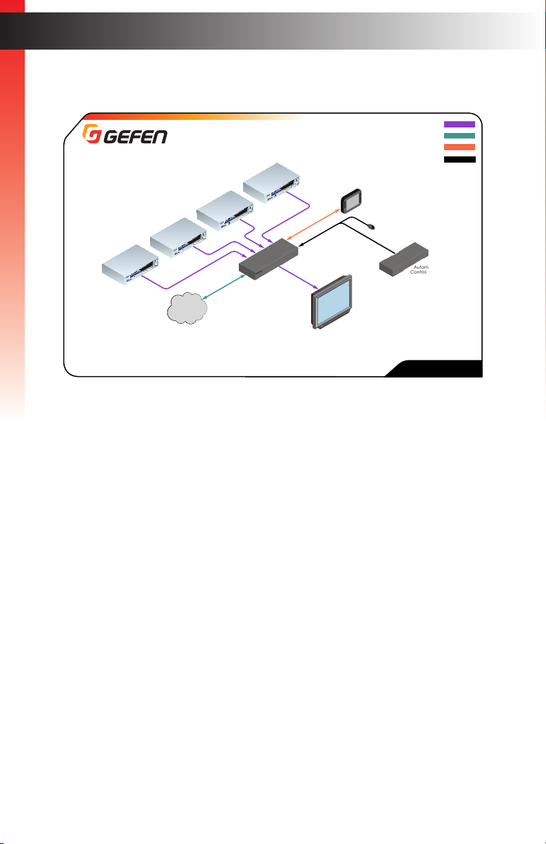
Ultra HD
Source
Sample Application Diagram
Ultra HD
Source
Ultra HD
Source
Ultra HD
Source
LAN
(for IP Control)
RS-232 Controller
Ultra HD 600 MHz
4x1 Switcher for HDMI
w/HDR
Ultra HD
Display
OR
HDMI CABLE
CAT-5 CABLE
RS-232 CABLE
EXT-RMT-EXTIRN
IR Extender
EXT-UHD600-41
Installation
IR
Automation
Control Device
page | 8
Page 19

This page left intentionally blank.
Page 20

This page left intentionally blank.
Page 21

4x1 Switcher for HDMI w/HDR
4K ULTRA
2 Basic Operation
Page 22
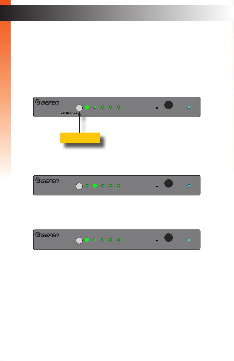
Switching Inputs
Using the Front Panel Buttons
The front panel of the Ultra HD 600 MHz 4x1 Switcher for HDMI w/HDR has a set of four
LED indicators which are associated with each input on the rear panel of the switcher.
Press the Input button to cycle through each of the inputs.
Basic OperationBasic Operation
1. When the switcher is powered-on for the rst time, input 1 will automatically
be selected.
4K 60 Hz 4:4:4, HDMI 2.0, HDCP 2.2
2. Press the Select button to select the next input. In this case, input 2.
4K 60 Hz 4:4:4, HDMI 2.0, HDCP 2.2
®
Select button
®
Select
Select
1 2 3 4
1 2 3 4
Off
Off
Reset Power
4K Ultra HD 600 MHz 4x1 Switcher w/HDR
Reset Power
4K Ultra HD 600 MHz 4x1 Switcher w/HDR
IR
IR
3. Consecutively press the Select button until the desired input is selected. Once input 4
is selected, pressing the Select button again will return the switcher to input 1.
Select
®
4K 60 Hz 4:4:4, HDMI 2.0, HDCP 2.2
1 2 3 4
Off
Reset Power
4K Ultra HD 600 MHz 4x1 Switcher w/HDR
IR
page | 12
Page 23
Switching Inputs
4K Ultra HD 600 MHz 4x1 Switcher w/HDR
Off
1 2 3 4
Select
®
4K 60 Hz 4:4:4, HDMI 2.0, HDCP 2.2
IR
Reset Power
R03,1.5V
R03,1.5V
ON
1 2
*Preferred
Using the IR Remote Control
The included IR remote control unit can also be used to switch between each input.
The front panel of the Ultra HD 600 MHz 4x1 Switcher for HDMI w/HDR has a set of four
(4) LED indicators which are associated with each input on the switcher.
Basic OperationBasic Operation
1. When the switcher is powered-on for the rst time, Input 1 (In 1) will automatically
be selected.
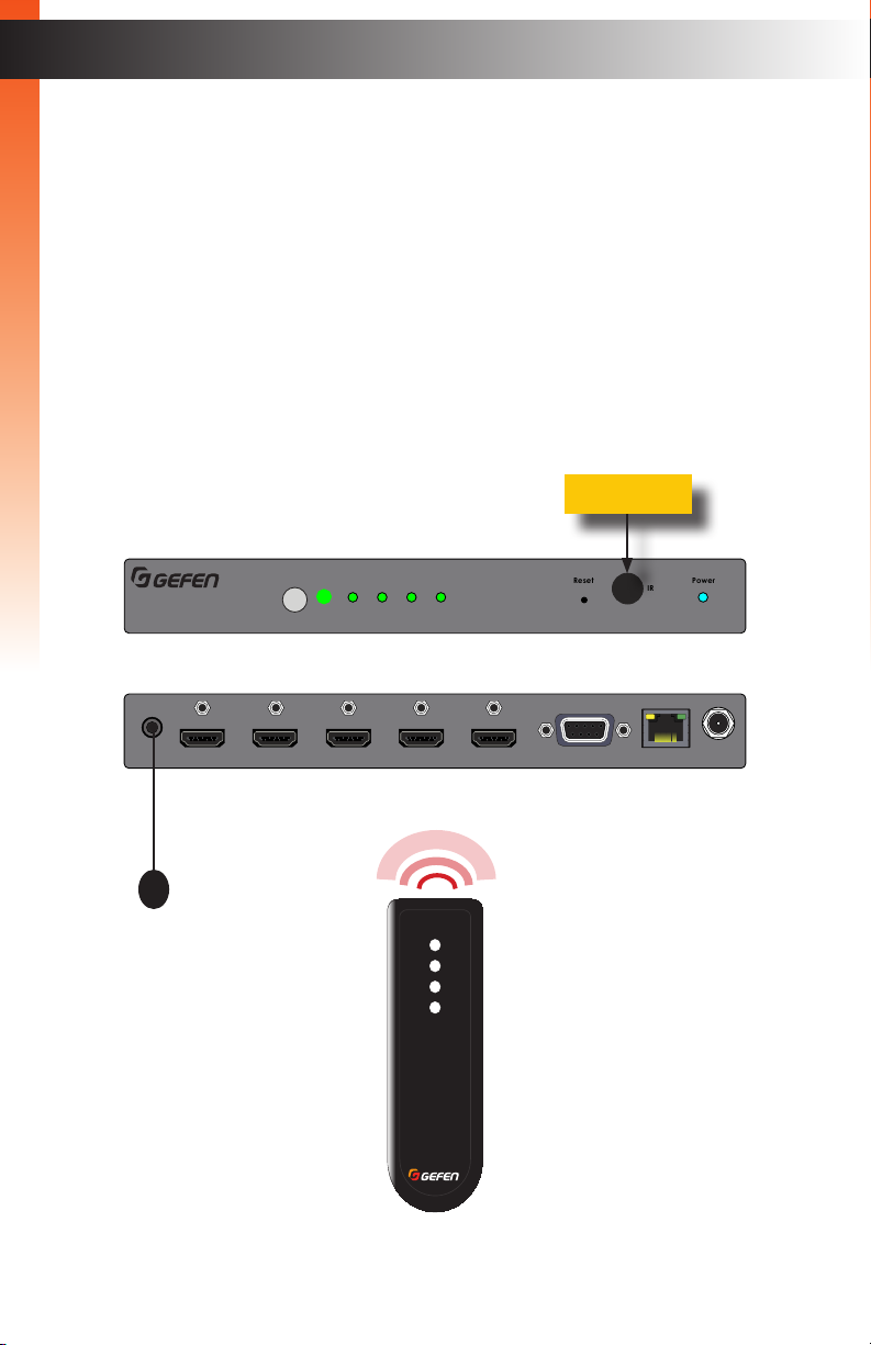
2. Point the included IR remote control unit at the IR sensor on the top panel. If an IR
extender is being used, then both IR sensors will be used to receive IR signals.
3. Each button on the IR remote control unit represents an input. Press the desired
source button on the IR remote control to switch to that input.
IR sensor
Select
®
4K 60 Hz 4:4:4, HDMI 2.0, HDCP 2.2
1 2 3 4
Off
Reset Power
IR
4K Ultra HD 600 MHz 4x1 Switcher w/HDR
EXT-UHD600-41
IR extender
In 2 In 3 In 4In 1Output (LRP)IR In/Ext
1
2
3
4
®
RMT-41
RS-232 IP Control
5V DC
page | 13
Page 24
The Web Interface
Introduction to the Web Interface
The 4x1 Switcher for HDMI w/HDR includes a built-in web interface. We recommend that
the web interface be used to control the switcher as it provides easy management of all
features used by the switcher.
Basic OperationBasic Operation
► Logging In
1. Launch your favorite web browser.
2. In the address bar, type the IP address of the switcher.
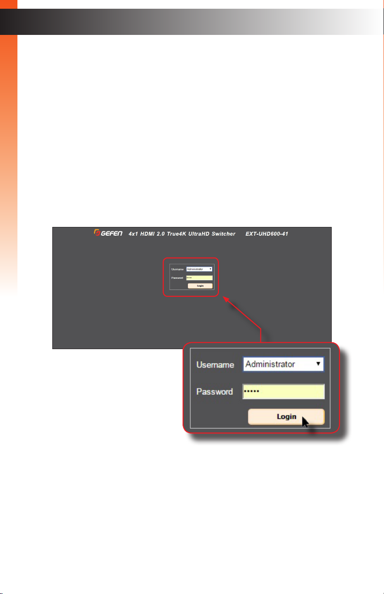
3. The login page will be displayed.
4. Select the user from the Username drop-down list.
• Operator
The Operator username provides restricted access to the web interface.
This username allows access to both the Routing and Status tabs.
The default password for the Operator user name is Operator.
All passwords are case-sensitive. For information on changing
the default password, see Conguring Network Settings (page 33).
page | 14
Page 25
Basic OperationBasic Operation
The Web Interface
• Administrator
The Administrator username provides full access to all features
within the web interface.
The default password for the Administrator user name is Admin.
All passwords are case-sensitive. For information on changing
the default password, see Conguring Network Settings (page 33).
5. Enter the password for the selected username.
6. Click the Login button.
7. The Routing tab will be displayed.
► Administrator vs Operator
As mentioned earlier, logging in as Operator provides restricted access to many
of the available features within the web interface. This is summarized in the table
below:
Administrator Operator
• Access to all features • Access to Routing and Status
tabs, only.
• No access to the Auto Switch
button under the Routing tab.
page | 15
Page 26
Basic OperationBasic Operation
The Web Interface
► Tabs and Sub-tabs
The web interface is organized into tabs, in the top-portion of the screen. Clicking on
a tab will display a different screen.
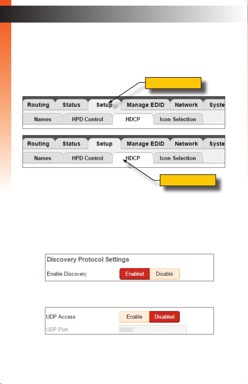
The Setup and Manage EDID tab have their own set of tabs, which we will refer to as
“sub-tabs”, as shown below.
Screen tab
Screen sub-tab
► Buttons
Several screen contain buttons which allow the selection of a particular mode or
setting. Click the button for the desired setting. Buttons that are red represent
a setting that is “turned on”. If the button is pale-yellow, then the feature is “turned off”:
• Example of a feature is “turned on”
• Example of a feature that is “turned off”
page | 16
Page 27
Basic OperationBasic Operation
The Web Interface
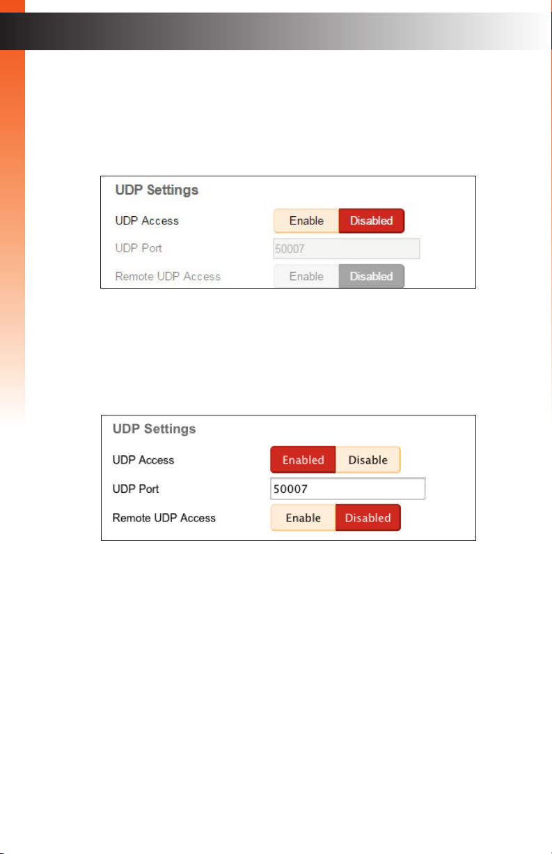
• If a button is light-gray or dark-gray (disabled), then this means that the setting
is not available. This usually requires that another setting must be enabled
before setting that feature.
For example, note that both the Remote UDP Access button and the UDP Port
eld are disabled in the illustration, below:
In order to change either of these settings, UDP Access must be enabled.
After clicking the Enable button, next to UDP Access, the button turns red and
reads “Enabled.” Since UDP Access is now enabled, we can now enable or
disable Remote UDP Access and/or change the UDP Port number:
page | 17
Page 28
The Web Interface
Routing
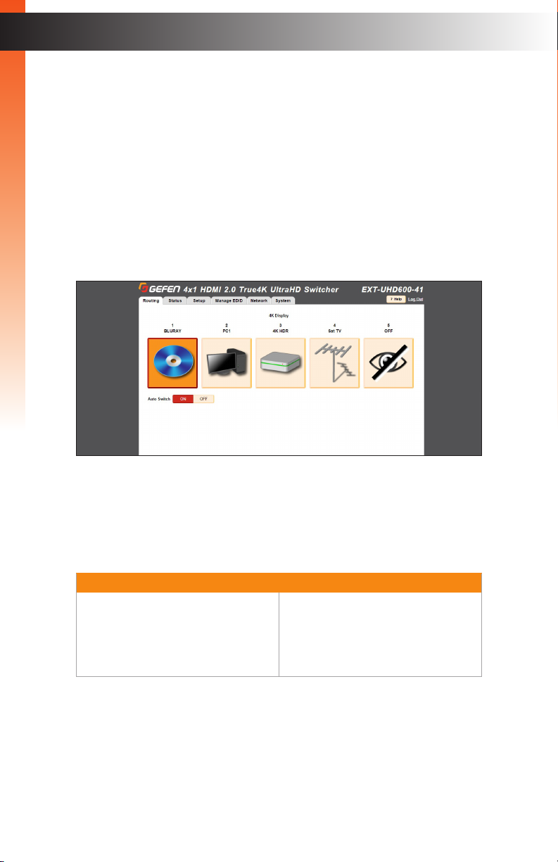
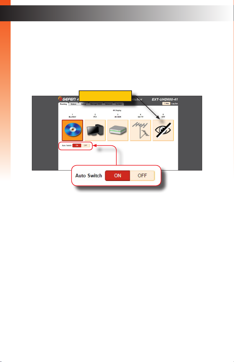
The Routing tab will be the rst tab to automatically be displayed after logging in to the
web interface.
1. Click the desired input from the list of icons. Once clicked, the icon background will
Basic OperationBasic Operation
turn orange, indicating that it is the currently-active input.
2. To prevent audio/video from being output, click the OFF button.
OFF button
3. The Auto Switch feature is disabled by default. Click the ON button to enable this
feature. When enabled, the device will automatically switch to the input that is
receives a hot-plug detect.
4. See Icon Selection (page 24) for information on changing the icon representation of
each “input”.
page | 18
Page 29
Input and Output Status
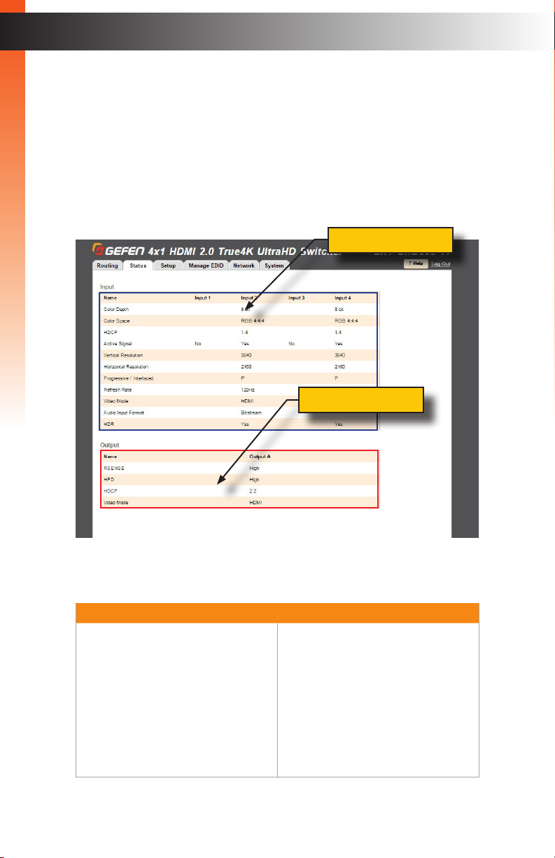
The Status tab provides video and audio information for all inputs and outputs.
1. Click the Status tab within the built-in web interface.
Basic OperationBasic Operation
2. Information on each input is listed in the top portion of the screen.
3. Information on each output is listed in the bottom portion of the screen.
The table below outlines the information that is available for each section:
Input Output
• Color depth
• Color space
• HDCP
• Active Signal
• Vertical resolution
• Horizontal Resolution
• Progressive / interlaced
• Refresh rate
• Video mode
• Audio Input Format
• HDR
• Rsense
• HDP
• HDCP
• Video mode
Input section
Output section
The Web Interface
page | 19
Page 30
The Web Interface
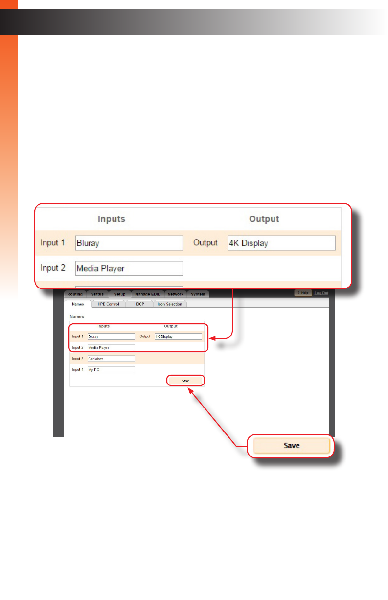
Changing Input and Output Names
By default, the names of the output is Output. The default names for each input are Input
1 - Input 4. Each of these names can be changed, as desired, to suit the type of device
that is connected to the input or output. This allows easy reference when performing
Basic OperationBasic Operation
routing operations.
1. Click the Setup tab within the built-in web interface.
2. Click the Names sub-tab.
3. Click in the eld of the desired output or input to be changed.
4. Once all changes have been made, click the Save button.
5. The new names will be displayed within the Routing tab.
page | 20
Page 31

The Web Interface
HPD Control
A Hot-Plug Detect (HPD) is a +5V signal that is sent from the source to the sink, once it is
connected using an HDMI cable. After receiving the signal, the sink device sends a +5V
HPD signal back to the source. HPD is used to begin communication between source and
Basic OperationBasic Operation
sink. Within the web interface, an HPD pulse can manually be sent to the source device
from the selected input.
1. Click the Setup tab within the built-in web interface.
2. Click the HPD Control sub-tab.
3. Click the Pulse button for the desired input. Click the Pulse All Inputs button to send
an HPD signal from all inputs.
page | 21
Page 32

The Web Interface
HDCP
This feature allows HDCP content to either be passed-through or rejected on each input.
Outputs can either follow the input status or can be set to always encode HDCP. Note that
using the “Reject” feature, on an input, does not decrypt HDCP content.
Basic OperationBasic Operation
1. Click the Setup tab within the built-in web interface.
2. Click the HDCP sub-tab.
3. For inputs, select the desired button next to the input.
► Reject - Does not allow HDCP content to be passed through. Click the
Reject All button to set all inputs to Reject.
► 2.2 - Click this button if the sink device supports HDCP 2.2. Click the
All 2.2 button to set all inputs to 2.2.
► 1.4 - Click this button if the sink device only supports HDCP 1.4. Click the
All 1.4 button to set all inputs to 1.4.
page | 22
Page 33

4. For the output, select either Follow Input of Always Encode.
► Follow Input - Click this button to have the output follow the setting used on the
input. Click the Follow All button to set all outputs to Follow Input.
► Always Encode - Encodes the output signal with HDCP, regardless of the input
Basic OperationBasic Operation
signal. Use this feature for displays that require HDCP-encoded content.
Click the All Encode button to set all outputs to Always Encode.
The Web Interface
page | 23
Page 34

The Web Interface
Icon Selection
Use the Icon Selection tab to select the desired icons which best represent each source
device in the system.
Basic OperationBasic Operation
1. Click the Setup tab within the built-in web interface.
2. Click the Icon Selection sub-tab.
3. Click the arrow, next to the icon, to change its appearance. Each input provides the
same icon choices.
page | 24
Page 35

The Web Interface
Setting the EDID Mode
The EDID Mode tab allows the desired EDID mode (internal preset, external, or custom)
to be set for each input.
Basic OperationBasic Operation
1. Click the Manage EDID tab within the built-in web interface.
2. Click the EDID Mode sub-tab.
3. Select the desired EDID mode for each input using the drop-down list.
If the EDID Mode is set to External, then the name of the downstream EDID (device)
will appear under the EDID Name column, as shown:
page | 25
Page 36

Basic OperationBasic Operation
The Web Interface
► Using a Custom EDID
The User-dened setting is used to store a custom EDID in the selected input.
To use a custom EDID, follow the instructions below:
1. SelectUser-dened from the drop-down list of the desired input.
2. Copy or upload an EDID to the input that is using the Custom mode.
See one of the following sections for more information on copying or
uploading EDID data:
► Copying EDID Data (page 27)
► Uploading and Downloading EDID Data (page 30)
3. Set the EDID Lock mode to either Locked or Unlocked:
► Locked
Prevents the EDID from being changed on the input..
► Unlocked
Allows the EDID to be changed.
4. The name of the custom EDID will appear under the EDID Name column.
page | 26
Page 37

The Web Interface
Copying EDID Data
The EDID Copy tab allows an EDID to be copied from an input or output (sink device) to
any input. In order to copy an EDID to an input, the input must be set to User-dened
mode and then unlocked. See Setting the EDID Mode (page 25) for more information.
Basic OperationBasic Operation
1. Click the Manage EDID tab within the built-in web interface.
2. Click the EDID Copy sub-tab.
3. Click the button of the output or input from the Select EDID to Copy section. Only
one input can be selected at a time.
page | 27
Page 38

The Web Interface
4. After an input or the output is selected, click the button for the corresponding input
where the EDID will be copied. One or more inputs can be selected at a time.
Basic OperationBasic Operation
5. Click the Copy button. The Copy can only be pressed when both the input (the
source) and the output (destination) are selected.
6. The EDID copy process is complete. Repeat steps 3 - 5 as desired.
page | 28
Page 39

Getting EDID Information
The EDID Info tab allows the EDID informatioin, from an input or sink device, to be
displayed.
Basic OperationBasic Operation
1. Click the Manage EDID tab within the built-in web interface.
2. Click the EDID Info sub-tab.
3. Select the desired input or output from the Choose EDID drop-down list.
The Web Interface
4. The EDID information for the selected input or output will be displayed.
page | 29
Page 40

The Web Interface
Uploading and Downloading EDID Data
The Upload / Download tab allows EDID data from an input, output, or one of the internal
EDID presets, to be downloaded and saved as a le on your computer. An EDID le can
also be uploaded to any (unlocked) input.
Basic OperationBasic Operation
► Downloading an EDID
1. Click the Manage EDID tab within the built-in web interface.
2. Click the Upload/Download sub-tab.
3. Select the desired input, output, or internal EDID preset to be downloaded
using the Select EDID File drop-down list.
4. Click the Download button.
page | 30
Page 41

Basic OperationBasic Operation
The Web Interface
5. The following dialog will be displayed:
6. Click the Save File button to save the EDID le to your computer.
• Mac OS X
The le will automatically be saved under
Macintosh HD\Users\[username]\Downloads.
• Windows OS
The le will be saved under
C:\Users\[username]\Downloads.
page | 31
Page 42

► Uploading an EDID
1. Click the Manage EDID tab within the built-in web interface.
2. Click the Upload/Download tab.
The Web Interface
Basic Operation
3. Select the input where the EDID le will be uploaded.
4. Set the input to Custom mode. See Setting the EDID Mode (page 25) for
more information.
5. Click the Browse... button under Upload EDID section.
6. The File Upload dialog will be displayed.
7. Select the EDID le from your computer. The EDID le must be in .bin format.
After the le is selected, click the OK button on the dialog box.
8. Select the input where the EDID will be uploaded using the Select
Destination drop-down list. In order for an input to be selected, it must be
unlocked and set to Custom. See Setting the EDID Mode (page 25) for more
information.
9. Click the Upload button.
page | 32
Page 43

The Web Interface
Configuring Network Settings
Once the switcher is congured on the network using Gefen Syner-G, the network settings
can be changed within the built-in web interface. To access the network settings, click the
Network tab in the built-in web interface.
Basic Operation
When changing any network setting, click the Save button at the bottom of the page.
To revert network settings to factory default, click the Set Network Defaults button.
► IP Settings
1. Set the network mode by clicking the Static or DHCP button.
2. If set to Static mode, then enter the IP address, subnet mask, and
gateway address in the IP Address, Subnet, and Gateway elds,
respectively. If set to DHCP mode, the DHCP server will assign these values.
3. Enter the HTTP listening port in the HTTP Port eld.
page | 33
Page 44

Basic Operation
The Web Interface
► TCP / Telnet Settings
For details on conguring TCP, see Using Telnet, UDP, and RS-232 (page 48).
• TCP Access: Click the Enable button to allow Telnet access to the switcher.
Otherwise, click the Disable button.
• TCP Port: Enter the TCP listening port in this eld.
• Login Message on Connect: Click the Show button to display the
welcome message at the beginning of a Telnet session. Otherwise, click
the Hide button.
• Require Password on Connect: Click the Enable button to require
password credentials at the beginning of a Telnet session.
page | 34
Page 45

The Web Interface
• User Name: This eld is static and cannot be changed. Telnet sessions
are restricted to Admin users.
• Old Password: Enter the old (current) password in this eld.
The factory-default password is Adm i n.
Basic Operation
• New Password: Enter the new password in this eld.
• ConrmNewPassword: Conrm the new password by entering the new
password in this eld.
Information
Note that all passwords are case-sensitive.
page | 35
Page 46

Basic Operation
The Web Interface
► UDP Settings
For details on conguring UDP, see Using Telnet, UDP, and RS-232 (page 48).
• UDP Access: Click the Enable button to use the UDP protocol with the switcher.
Otherwise, click the Disable button.
• UDP Port: Enter the TCP listening port in this eld.
• Remote UDP Access: Click the Enable button to set the remote UDP address
and UDP listening port. This feature only needs to be enabled if feedback to the
switcher is required. Otherwise, this feature can be disabled.
• Remote UDP IP Address: Enter the remote UDP IP address in this eld.
• Remote UDP Port: Enter the remote UDP listening port in this eld.
page | 36
Page 47

Basic Operation
The Web Interface
► Web Login Settings
• Username: To change the password for the Administrator, click the
Administrator. Otherwise, click the Operator button.
• New Password: Enter password for the selected username (above),
in this eld. Passwords are case-sensitive.
• Old Password: Enter the old (current) password in this eld. Passwords are
case-sensitive.
• ConrmNewPassword: To conrm the new password, re-enter the new
password in this eld. Passwords are case-sensitive.
The default password for the Administrator username is Adm i n.
The default password for the Operator username is O perat o r .
page | 37
Page 48

The Web Interface
► Discovery Protocol Settings
• Enable Discovery: Click the Enable button to enable “discovery” mode.
Otherwise, click the Disabled button. In order for Gefen Syner-G to
discover the switcher on a network, this feature must be enabled.
Basic Operation
• Find Your Device: Click the Show Me button to physically locate the switcher
on a network. In order for the Show Me button to be available, the Enable
Discovery button must be set to Enable. When the Show Me button is clicked,
the button text will change to Hide Me and all the LED indicators on the front
panel will flash.
4K 60 Hz 4:4:4, HDMI 2.0, HDCP 2.2
®
1 2 3 4
Off
Reset Power
4K Ultra HD 600 MHz 4x1 Switcher w/HDR
IR
Select
• Discovery Read Only: When set to Read Only, the IP settings for the
switcher will be displayed by Syner-G but they cannot be changed. In order
to display and change IP settings from within Gefen Syner-G, click the
Read / Write button.
• Product Description: EXT-UHD600-41 is the default product description.
This name will be used to identify the switcher when using the Gefen Syner-G
software.
page | 38
Page 49

The Web Interface
System Settings
The System tab provides controls for various other switcher features. Each of these
controls is described below.
Basic Operation
► Main RS-232 Feedback
By default, RS-232 feedback is set to On, meaning all command will send a response.
1. Click the Off button to disable RS-232 feedback.
2. Click the On button to enable RS-232 feedback.
► DownloadCurrentCongurationtoPC
Saves the current switcher conguration to a le on your computer.
1. Click the Download button.
2. The following dialog will be displayed (see following page).
page | 39
Page 50

Basic Operation
The Web Interface
3. Click the Save File radio button, then click OK to save the conguration le to
your computer.
• Mac OS X
The le will automatically be saved under
Macintosh HD\Users\[username]\Downloads
• Windows OS
The le will be saved under
C:\Users\[username]\Downloads
► Restore/UploadCongurationFile
Uploads the selected switcher conguration, from a le on your computer, to the
switcher.
1. Click the Browse... button.
page | 40
Page 51

The Web Interface
2. Select the desired conguration le from your computer. After the le has been
selected, the lename will appear next to the Browse... button.
3. Click the Restore button to upload the le.
Basic Operation
► Firmware Update
Uploads and applies the latest rmware le to the switcher.
1. Download the latest rmware from the Gefen web site.
2. Click the Browse... button.
3. Select the rmware le on your computer.
The rmware must be a .bin le and will have the following naming
convention: EXT-UHD600-41([version])(PACK).bin.
4. Click the Update button.
The following message box will be displayed:
WARNING: Updating the rmware may overwrite some
of your settings. Consider saving the conguration
before updating the rmware. Are you sure you want
to continue?
To save the conguration, before continuing, click the Cancel button on the
message box. Refer to the section DownloadCurrentCongurationtoPC.
page | 41
Page 52

Basic Operation
The Web Interface
6. Click the OK button.
7. After a few moments, the following message box will be displayed within the web
interface:
8. After the update process completes, the switcher will automatically reboot.
page | 42
Page 53

Basic Operation
The Web Interface
► Setting the LED Brightness
Sets the brightness for the LED indicators on the front panel of the switcher.
1. Drag the slider to set the LED brightness. The brightness ranges from 0 to 100.
The default setting is 50. The brightness value may also be entered directly, in
the box, next to the slider bar.
► Setting the IR Channel
Sets the IR channel for the switcher. The switcher must be set to the same IR
channel as the included IR remote control, in order for the IR remote control to
communicate with the switcher.
1. Click the desired IR channel for the switcher by clicking one of the
IR Channel buttons (1 - 4). The default IR channel setting is 1.
The IR channel setting is automatically saved. Rebooting the switcher
is not required.
page | 43
Page 54

Basic Operation
► Performing a Factory Reset
This feature restores the switcher to original factory-default settings.
1. Click the Reset button.
Important
Performing this function will erase all current setting of the switcher.
IP settings will be retained. To save the conguration, before continuing,
refer to the section DownloadCurrentCongurationtoPC.
The Web Interface
2. The following message box will be displayed:
► Click the OK button to continue with the reset procedure.
► Click the Cancel button to abort the reset procedure and return
to the web interface.
page | 44
Page 55

Basic Operation
The Web Interface
► Rebooting the Switcher
Clicking this button will reboot the switcher.
1. Click the Reboot button.
2. The following message box will be displayed:
► Click the OK button to continue with the reboot procedure.
► Click the Cancel button to abort the reboot procedure and return
to the web interface.
page | 45
Page 56

This page left intentionally blank.
Page 57

4x1 Switcher for HDMI w/HDR
4K ULTRA
3 Advanced Operation
Page 58

Using Telnet, UDP, and RS-232
Telnet Configuration
1. Launch the desired terminal application. For example, on the Windows operating
system, Hyperterminal can be used; on Mac OS X, the Terminal application can be
used.
2. After correct settings have been used in the terminal program, information similar to
Advanced Operation
the following will be displayed:
Welcome to EXT-UHD600-41 Telnet
telnet->
3. Type #help for a list of commands or refer to the tables on the following pages.
UDP Configuration
1. Congure the desired control system for UDP.
2. Click the Network tab, within the web interface, and do the following.
See Conguring Network Settings (page 33) for more information.
a. Click the Enabled button next to UDP Access.
b. Enter the UDP listening port in the UDP Port eld. The default UDP listening port
is 50007.
c. Click the Enabled button next to Remote UDP Access. This feature only needs
to be enabled if feedback to the switcher is required. Otherwise, this feature can
be disabled.
d. If enabling Remote UDP Access, enter the remote UDP IP address in the
Remote UDP IP Address eld. This IP address should be the same as the
control system. The default IP address is 192.168.1.255.
e. If enabling Remote UDP Access, enter the remote UDP listening port in the
Remote UDP Port eld. The default remote UDP listening port is 50008.
f. Click the Save button at the bottom of the Network screen.
page | 48
Page 59

Using Telnet, UDP, and RS-232
DE-9
RS-232 Configuration
1. Congure...
2. Selected the desired COM port.
3. Congure the RS-232 port to the following settings. Note that Only TxD, RxD,
and GND pins are used.
RS-232 Controller Switcher
DCD
RXD
TXD
DTR
GND
DSR
RTS
CTS
R1
1
2
3
4
5
6
7
8
9
564738291
1
2
3
4
5
6
7
8
9
DCD
RXD
TXD
DTR
GND
DSR
RTS
CTS
R1
Description Setting
Baud rate
Data bits
Parity
Stop bits
Hardware ow control
19200
8
None
1
None
4. Connect the RS-232 cable from the DB9 connector on the controller to the to the
RS-232 port on the switcher.
5. Type #help for a list of commands or refer to the tables on the following pages.
page | 49
Page 60

Commands
Discovery Service
#get_device_desc
#get_discovery
#get_discovery_mode
#get_showme
#set_device_desc
Advanced Operation
#set_discovery
#set_discovery_mode
#set_showme
Help
#help
Input Status
#gets_input_hdcp
#gets_input_hpd
#gets_input_mode
#gets_input_signal
Returns the current device-description string
Returns the current state of the discovery service
Returns the discovery mode
Returns the status of the “show me” feature
Sets the description string of the switcher
Enables or disables the discovery service
Sets the “discovery” mode
Enables or disables the “show me” feature
Returns a list of available commands
Returns the HDCP state on the specied input
Returns the HPD state on the specied input
Returns the input mode on the specied input
Returns the signal status on the specied input
Manage EDID
#get_ds_edid
#get_edid_mode
#get_ext_edid
#get_preset_edid
#set_edid_copy
#set_edid_lock
#set_edid_mode
Downloads the downstream EDID
Returns the EDID mode on the specied input
Downloads the external EDID
Downloads the specied preset EDID
Copies the specifed EDID to the custom EDID
Sets the EDID lock setting on the specied input
Sets the EDID mode
page | 50
Page 61

Network Settings
#get_gateway
#get_http_port
#get_ip_address
#get_ip_mode
#get_ipcong
Advanced Operation
#get_mac_addr
#get_netmask
#get_remote_udp_access
#get_remote_udp_ip
#get_remote_udp_port
#get_telnet_access
#get_telnet_port
#get_telnet_welcome
#get_udp_access
#get_udp_port
#set_gateway
#set_http_port
#set_ip_address
#set_ip_mode
#set_netmask
#set_remote_udp_access
#set_remote_udp_ip
#set_remote_udp_port
#set_telnet_access
#set_telnet_port
#set_telnet_welcome
#set_udp_access
#set_udp_port
#use_telnet_login
Commands
Returns the gateway IP address of the switcher
Returns the HTTP listening port
Returns the IP address
Returns the IP mode
Returns the IP conguration
Returns the MAC address
Returns the subnet mask
Returns the remote UDP access state
Returns the remote UDP IP address
Returns the remote UDP listening port
Returns the Telnet access state
Returns the Telnet listening port
Returns the Telnet welcome message
Returns the UDP access state
Returns the UDP listening port
Sets the gateway address
Sets the HTTP listening port
Sets the IP address
Sets the IP mode
Sets the subnet mask
Enables or disables remote UDP access
Sets the remote UDP IP address
Sets the remote UDP listening port
Enables or disables Telnet access
Sets the Telnet listening port on the switcher
Sets the Telnet welcome message
Enables or disables UDP access
Sets the UDP listening port
Enable or disables Telnet login credentials
page | 51
Page 62

Output Status
#gets_output_hdcp
#gets_output_hpd
#gets_output_rsense
Advanced Operation
Routing
#get_auto_switch
#lock_matrix
#set_auto_switch
r
System Settings
#factory_reset
#get_feedback
#get_ir_channel
#get_led_brightness
#reboot
#set_feedback
#set_ir_channel
#set_led_brightness
#show_rmware_version
Commands
Returns the HDCP state of the output
Returns the HDP state of the output
Returns the Rsense state of the output
Returns the status of the auto-switching feature
Locks / unlocks the switcher
Enables / disables the auto-switching feature
Routes the specied input to the output
Resets the switcher to factory-default settings
Returns the RS-232 feedback state
Returns the current IR channel
Returns the LED brightness level
Reboots the switcher
Enables / disables unsolicited RS-232 feedback
Sets the IR channel
Sets the LED brightness level
Returns the current rmware version
page | 52
Page 63

#get_device_desc
Returns the description of the switcher.
Syntax
#get_device_desc
Advanced Operation
Parameters
None
Example
#get_device_desc
DEVICE DESCRIPTION IS EXT-UHD600-41
Related Commands
Commands
#get_discovery
#get_discovery_mode
#get_showme
#set_device_desc
#set_discovery
#set_discovery_mode
#set_showme
page | 53
Page 64

#get_discovery
Returns the discovery mode setting. The value returned is one of the following:
Value Description
0
1
Advanced Operation
Syntax
#get_discovery
Parameters
None
Example
#get_discovery
DISCOVERY 1
“Discovery” mode is disabled
“Discovery” mode is enabled
Commands
Related Commands
#get_device_desc
#get_discovery_mode
#get_showme
#set_device_desc
#set_discovery
#set_discovery_mode
#set_showme
page | 54
Page 65

#get_discovery_mode
Returns the current “discovery” mode. The value returned is one of the following:
Value Description
0
1
Advanced Operation
Syntax
#get_discovery_mode
Parameters
None
Example
#get_discovery_mode
#get_discovery_mode 1
Read only
Read / Write
Commands
Related Commands
#get_device_desc
#get_discovery
#get_showme
#set_device_desc
#set_discovery
#set_discovery_mode
#set_showme
page | 55
Page 66

#get_showme
Returns the current “show me” state. When the switcher is in “show me” mode, the LED
indicators on the front panel will be ash. In this state, the #get_showme command will
return a value of 1. Otherwise, a value of 0 will be returned.
Value Description
0
Advanced Operation
1
Syntax
#get_showme
Parameters
None
Example
“Show me” disabled
“Show me” enabled.
Commands
#get_showme
#get_showme 1
Related Commands
#get_device_desc
#get_discovery
#get_discovery_mode
#set_device_desc
#set_discovery
#set_discovery_mode
#set_showme
page | 56
Page 67

#set_device_desc
Sets the switcher identier string.
Syntax
#set_device_desc name
Advanced Operation
Parameters
name
Type: STRING
The device description. This value cannot exceed 30 characters in length.
Example
#set_device_desc switcher202
DEVICE DESCRIPTION IS SET TO switcher202
Commands
Related Commands
#get_device_desc
#get_discovery
#get_discovery_mode
#get_showme
#set_discovery
#set_discovery_mode
#set_showme
page | 57
Page 68

#set_discovery
Enables or disables the “discovery” feature. This feature is enabled by default.
Syntax
#set_discovery state
Advanced Operation
Parameters
state
Type: INTEGER
Accepts a number from the table below, specifying the desired state:
state Description
0
1
If set to disabled, then the Syner-G Software Suite will be unable to detect the
switcher on a network. It is recommended that this feature is enabled, until the
switcher has been congured for use on a network.
Disables “Discovery” mode
Enables “Discovery” mode
Commands
Example
#set_discovery 0
DISCOVERY 0
Related Commands
#get_device_desc
#get_discovery
#get_discovery_mode
#get_showme
#set_device_desc
#set_discovery_mode
#set_showme
page | 58
Page 69

#set_discovery_mode
Sets the “discovery” mode. This mode is set to read/write by default.
Syntax
#set_discovery_mode mode
Advanced Operation
Parameters
mode
Type: INTEGER
Accepts a number from the table below, specifying the desired state:
mode Description
0
1
When set to read-only mode, the IP settings for the switcher will be displayed
within the Gefen Syner-G Software Suite but cannot be changed. In order to
both display and allow changes to the IP settings within Gefen Syner-G,
set this feature to read/write mode.
Read-only mode
Read / write mode
Commands
Example
#set_discovery_mode 0
DISCOVERY MODE 0
Related Commands
#get_device_desc
#get_discovery
#get_discovery_mode
#get_showme
#set_device_desc
#set_discovery
#set_showme
page | 59
Page 70

#set_showme
Enables or disables the “Show Me” feature. If the “Show Me” feature is enabled,
then all the buttons (with the exception of the Power button), will ash slowly.
This feature allows the switcher to be visually identied on the network and is useful
when multiple switcher units are being used. The default setting is disabled.
Advanced Operation
Syntax
#set_showme state
Parameters
state
Type: INTEGER
Accepts a number from the table below, corresponding to the desired state.
state Description
0
1
Disable “Show Me”
Enable “Show Me”
Commands
Example
#set_showme 1
SET_SHOWME 1
Related Commands
#get_device_desc
#get_discovery
#get_discovery_mode
#get_showme
#set_device_desc
#set_discovery
#set_discovery_mode
page | 60
Page 71

#help
Returns a list of available commands. The commands listed are specic to either the
Sender or Receiver unit.
Syntax
Advanced Operation
#help
Parameters
None
Example
#help
Commands
page | 61
Page 72

#gets_input_hdcp
Returns the HDCP mode of the specied input. The value returned is one of the following:
Value Description
0
1
Advanced Operation
2
Syntax
#gets_input_hdcp input
Parameters
input
Type: INTEGER
The number of the HDMI input (1 - 4) to query.
Reject
HDCP 2.2 and below
HDCP 1.4 and below
Commands
Example
#get_input_hdcp 1
INPUT_HDCP 1 0
Related Commands
#gets_input_hpd
#gets_input_mode
#gets_input_signal
#gets_output_hdcp
#gets_output_hpd
#gets_output_rsense
page | 62
Page 73

#gets_input_hpd
Returns the HPD status of the specied input.
Value Description
0
1
Advanced Operation
Syntax
#gets_input_hpd input
Parameters
input
Type: INTEGER
The number of the HDMI input (1 - 4) to query.
HPD low (no source connected)
HPD high (source connected)
Commands
Example
#gets_input_hpd 1
INPUT_HPD 1 0
Related Commands
#gets_input_hdcp
#gets_input_mode
#gets_input_signal
#gets_output_hdcp
#gets_output_hpd
#gets_output_rsense
page | 63
Page 74

#gets_input_mode
Returns the video mode of the specied input(s). The value returned is one of the
following. To return the video mode for all inputs, specify 0 for the input parameter.
Value Description
D
Advanced Operation
H
Syntax
#gets_input_mode inputs
Parameters
input
Type: INTEGER
The number of the HDMI input (1 - 4) to query. More than one input can be
specied.
DVI signal detected on HDMI input
HDMI signal detected on HDMI input
Commands
Example
#gets_input_mode 1
INPUT_MODE 1 H
#get_input_mode 0
INPUT_MODE 0 H H L H
Related Commands
#gets_input_hdcp
#gets_input_hpd
#gets_input_signal
#gets_output_hdcp
#gets_output_hpd
#gets_output_rsense
page | 64
Page 75

#gets_input_signal
Returns the active signal status of the specied input(s). The value returned is one of the
following.
Value Description
N
Advanced Operation
Y
Syntax
#gets_input_signal inputs
Parameters
input
Type: INTEGER
The number of the HDMI input (1 - 4) to query. More than one input can be
specied.
No clock signal present on HDMI nput
Valid clock signal detected on HDMI input
Commands
Example
#gets_input_signal 0
INPUT_SIGNAL 0 Y Y Y Y
#gets_input_signal 1
INPUT_SIGNAL 1 Y
Related Commands
#gets_input_hdcp
#gets_input_hpd
#gets_input_mode
#gets_output_hdcp
#gets_output_hpd
#gets_output_rsense
page | 65
Page 76

#get_ds_edid
Downloads the downstream EDID.
Syntax
#gets_ds_edid input
Advanced Operation
Parameters
input
Type: INTEGER
The number of the HDMI input (1 - 4) to query.
Example
#gets_ds_edid 1
00FFFFFFFFFFFF000421000000000000...
Commands
Related Commands
#get_edid_mode
#get_ext_edid
#get_preset_edid
#set_edid_copy
#set_edid_lock
#set_edid_mode
page | 66
Page 77

#get_edid_mode
Returns the EDID mode of the specied input. The value returned is one of the following:
Value Description
1
2
Advanced Operation
3
4
5
6
7
8
Syntax
#get_edid_mode input
Internal Mode - UHD 600 4K 2 Channel
Internal Mode - UHD 600 4K Multichannel
Internal Mode - UHD 300 4K 2 Channel
Internal Mode - UHD 300 4K 2 Multichannel
Internal Mode - 1080p 2 Channel
Internal Mode - 1080p Multichannel
Custom Mode - User
External
Commands
Parameters
input
Type: INTEGER
The number of the HDMI input (1 - 4) to query.
Example
#get_edid_mode 1
#get_edid_mode 1 0
Related Commands
#get_ds_edid
#get_ext_edid
#get_preset_edid
#set_edid_copy
#set_edid_lock
#set_edid_mode
page | 67
Page 78

#get_ext_edid
Downloads the external EDID.
Syntax
#get_ext_edid input
Advanced Operation
Parameters
input
Type: INTEGER
The number of the HDMI input (1 - 4) to query.
Example
#get_ext_edid 1
00FFFFFFFFFFFF000421000000000000...
Commands
Related Commands
#get_ds_edid
#get_edid_mode
#get_preset_edid
#set_edid_copy
#set_edid_lock
#set_edid_mode
page | 68
Page 79

#get_preset_edid
Returns the EDID mode of the specied input. The value returned is one of the following:
Syntax
#get_preset_edid edid
Advanced Operation
Parameters
edid
Type: INTEGER
Accepts a number from the table below, corresponding to the desired EDID.
edid Description
1
2
3
4
5
6
Internal Mode - UHD 600 4K 2Ch
Internal Mode - UHD 600 4K Multichannel
Custom Mode - UHD 300 4K 2Ch
Custom Mode - UHD 300 4K Multichannel
Custom Mode - 1080p 2Ch
Custom Mode - 1080p Multichannel
Commands
Example
#get_preset_edid 1
00FFFFFFFFFFFF000421000000000000...
Related Commands
#get_ds_edid
#get_edid_mode
#get_ext_edid
#set_edid_copy
#set_edid_lock
#set_edid_mode
page | 69
Page 80

#set_edid_copy
Copies the external, internal, or output EDID to the custom user EDID.
Syntax
#set_edid_copy edid
Advanced Operation
Parameters
edid
Type: INTEGER
Accepts a number from the table below, corresponding to the desired EDID.
edid Description
1
2
3
4
5
6
7
Internal Mode - UHD 600 4K 2Ch
Internal Mode - UHD 600 4K Multichannel
Custom Mode - UHD 300 4K 2Ch
Custom Mode - UHD 300 4K Multichannel
Custom Mode - 1080p 2Ch
Custom Mode - 1080p Multichannel
External
Commands
Example
#set_edid_copy 1
COPY_COMPLETE
Related Commands
#get_ds_edid
#get_edid_mode
#get_ext_edid
#get_preset_edid
#set_edid_lock
#set_edid_mode
page | 70
Page 81

#set_edid_lock
Locks to unlocks the EDID when using Custom EDID mode. This command only works
if the specied input is set to a Custom mode. See the #set_edid_mode command.
Syntax
Advanced Operation
#set_edid_lock input state
Parameters
input
Type: INTEGER
This parameter must be the identier of an HDMI input (1 - 4).
state
Type: INTEGER
Accepts a number from the table below, specifying the desired state:
state Description
0
1
Unlock the EDID
Lock the EDID
Commands
Example
#set_edid_lock 1 0
EDID_LOCK 1 0
Related Commands
#get_ds_edid
#get_edid_mode
#get_ext_edid
#get_preset_edid
#set_edid_copy
#set_edid_mode
page | 71
Page 82

#set_edid_mode
Sets the EDID mode.
Syntax
#set_edid_mode edid
Advanced Operation
Parameters
edid
Type: INTEGER
Accepts a number from the table below, corresponding to the desired EDID.
edid Description
1
2
3
4
5
6
7
8
Internal Mode - UHD 600 4K 2Ch
Internal Mode - UHD 600 4K Multichannel
Custom Mode - UHD 300 4K 2Ch
Custom Mode - UHD 300 4K Multichannel
Custom Mode - 1080p 2Ch
Custom Mode - 1080p Multichannel
Custom Mode - User
External
Commands
Example
#set_edid_mode 1
EDID_MODE 1
Related Commands
#get_ds_edid
#get_edid_mode
#get_ext_edid
#get_preset_edid
#set_edid_copy
#set_edid_lock
page | 72
Page 83

#get_gateway
Returns the gateway address of the switcher.
Syntax
#get_gateway
Advanced Operation
Parameters
None
Example
#get_gateway
GATEWAY 10.5.64.1
Related Commands
Commands
#get_http_port
#get_ip_address
#get_ip_mode
#get_ipcong
#get_netmask
#set_gateway
#set_http_port
#set_ip_address
#set_ip_mode
#set_netmask
page | 73
Page 84

#get_http_port
Returns the HTTP listening port of the switcher.
Syntax
#get_http_port
Advanced Operation
Parameters
None
Example
#get_http_port
HTTP_PORT 80
Related Commands
Commands
#get_gateway
#get_ip_address
#get_ip_mode
#get_ipcong
#get_netmask
#set_gateway
#set_http_port
#set_ip_address
#set_ip_mode
#set_netmask
page | 74
Page 85

#get_ip_address
Returns the current IP address of the switcher.
Syntax
#get_ip_address
Advanced Operation
Parameters
None
Example
#get_ip_address
IP_ADDRESS 10.5.64.81
Related Commands
Commands
#get_gateway
#get_http_port
#get_ip_mode
#get_ipcong
#get_netmask
#set_gateway
#set_http_port
#set_ip_address
#set_ip_mode
#set_netmask
page | 75
Page 86

#get_ip_mode
Returns the current IP mode of the switcher. The value returned is one of the following:
Value Description
Advanced Operation
Syntax
#get_ip_mode
Parameters
None
Example
#get_ip_mode
IP_MODE 0
0
1
Static mode
DHCP mode
Commands
Related Commands
#get_gateway
#get_http_port
#get_ip_address
#get_ipcong
#get_netmask
#set_gateway
#set_http_port
#set_ip_address
#set_ip_mode
#set_netmask
page | 76
Page 87

#get_ipcong
Returns the current IP conguration of the switcher. In addition to providing the MAC
address and the broadcast IP address, this command also provides the same
information as executing the #get_ip_address, #get_netmask, #get_gateway,
and #get_mac_addr ommands.
Advanced Operation
Syntax
#get_ipcong
Parameters
None
Example
#get_ipcong
IP CONFIGURATION IS :
IP: 10.5.64.81
NETMASK: 255.255.255.0
GATEWAY: 10.5.64.1
MAC ADDRESS: 00:1C:91:04:90:03
Commands
Related Commands
#get_gateway
#get_http_port
#get_ip_address
#get_ip_mode
#get_netmask
#set_gateway
#set_http_port
#set_ip_address
#set_ip_mode
#set_netmask
page | 77
Page 88

#get_mac_addr
Returns the MAC address of the switcher.
Syntax
#get_mac_addr
Advanced Operation
Parameters
None
Example
#get_mac_addr
MAC ADDRESS IS: 00:1C:91:04:90:03
Related Commands
Commands
#get_ipcong
page | 78
Page 89

#get_netmask
Returns the current subnet mask of the switcher.
Syntax
#get_netmask
Advanced Operation
Parameters
None
Example
#get_netmask
NETMASK 255.255.255.0
Related Commands
Commands
#get_gateway
#get_http_port
#get_ip_address
#get_ip_mode
#get_ipcong
#set_gateway
#set_http_port
#set_ip_address
#set_ip_mode
#set_netmask
page | 79
Page 90

#get_remote_udp_access
Returns the remote UDP access state. The value returned is one of the following:
Value Description
0
1
Advanced Operation
Syntax
#get_remote_udp_access
Parameters
None
Example
#get_remote_udp_access
REMOTE_UDP_ACCESS 0
Remote UDP access disabled
Remote UDP access enabled
Commands
Related Commands
#get_remote_udp_access
#get_remote_udp_ip
#get_remote_udp_port
#get_udp_access
#get_udp_port
#set_remote_udp_access
#set_remote_udp_ip
#set_remote_udp_port
#set_udp_access
#set_udp_port
page | 80
Page 91

#get_remote_udp_ip
Returns the remote UDP IP address.
Syntax
#get_remote_udp_ip
Advanced Operation
Parameters
None
Example
#get_remote_udp_access
REMOTE_UDP_IP 192.168.1.255
Related Commands
Commands
#get_remote_udp_access
#get_remote_udp_port
#get_udp_access
#get_udp_port
#set_remote_udp_access
#set_remote_udp_ip
#set_remote_udp_port
#set_udp_access
#set_udp_port
page | 81
Page 92

#get_remote_udp_port
Returns the remote UDP listening port.
Syntax
#get_remote_udp_port
Advanced Operation
Parameters
None
Example
#get_remote_udp_port
REMOTE_UDP_PORT 50008
Related Commands
Commands
#get_remote_udp_access
#get_remote_udp_ip
#get_udp_access
#get_udp_port
#set_remote_udp_access
#set_remote_udp_ip
#set_remote_udp_port
#set_udp_access
#set_udp_port
page | 82
Page 93

#get_telnet_access
Returns the Telnet access state. Use the #set_telnet_access command to enable
or disable Telnet access.
Syntax
Advanced Operation
#get_telnet_access
Parameters
None
Example
#get_telnet_access
TELNET_ACCESS 1
Related Commands
Commands
#get_telnet_port
#get_telnet_welcome
#set_telnet_access
#set_telnet_port
#set_telnet_welcome
#use_telnet_login
page | 83
Page 94

#get_telnet_port
Returns the Telnet listening port.
Syntax
#get_telnet_port
Advanced Operation
Parameters
None
Example
#get_telnet_port
TELNET_PORT 23
Related Commands
Commands
#get_telnet_access
#get_telnet_welcome
#set_telnet_access
#set_telnet_port
#set_telnet_welcome
#use_telnet_login
page | 84
Page 95

#get_telnet_welcome
Returns the Telnet welcome message. Use the #set_telnet_welcome to create
a custom welcome message.
Syntax
Advanced Operation
#get_telnet_welcome
Parameters
None
Example
#get_telnet_welcome
TELNET WELCOME SCREEN IS ENABLED
Related Commands
Commands
#get_telnet_access
#get_telnet_port
#set_telnet_access
#set_telnet_port
#set_telnet_welcome
#use_telnet_login
page | 85
Page 96

#get_udp_access
Returns the UDP access state. Use the #set_udp_access command to enable
or disable UDP access. The value returned is one of the following:
Value Description
0
Advanced Operation
1
Syntax
#get_udp_access
Parameters
None
Example
UDP access disabled
UDP access enabled
Commands
#get_udp_access
UDP_ACCESS 0
Related Commands
#get_remote_udp_access
#get_remote_udp_ip
#get_remote_udp_port
#get_udp_port
#set_remote_udp_access
#set_remote_udp_ip
#set_remote_udp_port
#set_udp_access
#set_udp_port
page | 86
Page 97

#get_udp_port
Returns the local UDP listening port.
Syntax
#get_udp_port
Advanced Operation
Parameters
None
Example
#get_udp_port
UDP_PORT 50007
Related Commands
Commands
#get_remote_udp_access
#get_remote_udp_ip
#get_remote_udp_port
#get_udp_access
#set_remote_udp_access
#set_remote_udp_ip
#set_remote_udp_port
#set_udp_access
#set_udp_port
page | 87
Page 98

#set_gateway
Sets the gateway address for the switcher. The gateway address will be changed only if
the switcher is in static IP mode. If the switcher is using DHCP mode, then the gateway
address is automatically assigned by the DHCP server. The switcher must be rebooted
after executing this command.
Advanced Operation
Syntax
#set_gateway addr
Parameters
addr
Type: IP ADDRESS
The desired gateway address of the switcher. This address must be entered
in dot-decimal notation.
Example
Commands
#set_gateway 10.5.64.1
GATEWAY 10.5.64.1
REBOOT TO APPLY SETTINGS
Related Commands
#get_gateway
#get_http_port
#get_ip_address
#get_ip_mode
#get_ipcong
#get_netmask
#set_http_port
#set_ip_address
#set_ip_mode
#set_netmask
page | 88
Page 99

#set_http_port
Sets the HTTP listening port for the switcher.
Syntax
#set_http port
Advanced Operation
Parameters
port
Type: INTEGER
The desired HTTP listening port for the switcher.
Example
#set_http_port 80
HTTP_PORT 80
Commands
Related Commands
#get_gateway
#get_http_port
#get_ip_address
#get_ip_mode
#get_ipcong
#get_netmask
#set_gateway
#set_ip_address
#set_ip_mode
#set_netmask
page | 89
Page 100

#set_ip_address
Sets the IP address of the switcher. The switcher must be rebooted after executing this
command.
Syntax
Advanced Operation
#set_ip_address addr
Parameters
addr
Type: IP ADDRESS
The desired IP address of the switcher. This address must be entered
in dot-decimal notation.
Example
#set_ip_address 10.5.64.81
IP_ADDRESS 10.5.64.81
REBOOT TO APPLY SETTINGS
Commands
Related Commands
#get_gateway
#get_http_port
#get_ip_address
#get_ip_mode
#get_ipcong
#get_netmask
#set_gateway
#set_http_port
#set_ip_mode
#set_netmask
page | 90
 Loading...