

Page 1
EXT-TV-M
FS
an
w
®
®
M
l
ww.gefen.co
®
1080P
Page 2

Page 3

ASKING FOR ASSISTANC
E
T
t
0
0
0
T
:
e
:
C
e
0600
1
e
T
C
©
d
9
echnical Suppor
Telephone (818) 772-910
(800) 545-690
Fax (818) 772-912
echnical Support Hours
:00 AM to 5:00 PM Monday through Friday, Pacifi c Tim
Write To
efen, LL
o Customer Servic
2
Nordhoff St
hatsworth, CA 9131
www.gefen.com
upport@gefen.com
Notic
efen, LLC reserves the right to make changes in the hard ware, packaging and
any accompanying doc u men ta tion without prior written notice.
V Multi Format Switcher is a trademark of Gefen, LL
2010 Gefen, LLC, All Rights Reserve
All trademarks are the property of their respective owners.
Rev A
Page 4

CONTENT
S
oduction
yout
y
e
n
y
1 Intr
2 Operation Notes
Features
4 Panel La
4 Front Panel
Back Panel
Panel Descriptions
IR Remote Control
Layout and Descriptions
Installing the Batter
Setting the IR channel
10 Connecting the TV Multi Format Switcher
11 Operating the TV Multi Format Switcher
11 Selecting the Input Sourc
12 Setting the IR channel
14 RS-232 Serial Control
15 RS-232 Commands
16 Rack Mount Installatio
17 Specifi cations
18 Warrant
Page 5

INTRODUCTIO
N
y
ongratulations on your purchase of the Gefen TV Multi Format Switcher. Your
omplete satisfaction is very important to us.
efen
efen delivers innovative, progressive computer and electronics add-on solutions
that harness integration, extension, distribution and conversion technologies.
efen’s reliable, plug-and-play products supplement cross-platform computer
stems, professional audio/video environments and HDTV systems of all sizes
with hard-working solutions that are easy to implement and simple to operate.
How It Works
The rack-mountable TV Multi Format Switcher allows you to view a wide variety
of analog and digital SD and HD video sources with audio at resolutions up to
1080p -- all on one HDMI-compliant display. Anything from computers, set-top
boxes, satellite boxes, security cameras, Blu-ray and DVD players to the next
eneration of hi-def gaming consoles (including the Xbox 360 and PS3) can
hare a single HDMI-compliant display. Superior A/V signal quality is insured by
the 3D comb fi lter and 3D noise reduction circuitry. The audio delay feature and
de-interlacing feature for 480i sources improves Standard-Defi nition console
aming.
The TV Multi Format Switcher supports 2 Component, 2 Composite, 2 S-Video,
and 1 VGA source -- each with L/R analog audio in up to 2 channels. 3 HDMI
ources are also supported with embedded digital audio at up to 7.1 channels.
The number of audio channels present in the HDMI output signal will depend on
what kind of audio is input). Any A/V source can be selected for viewing at an
time using the included IR remote or the front-panel selector buttons.
How It Works
Audio/video sources connect to the TV Multi Format Switcher on its inputs. An
DMI-compliant display is connected to the HDMI output. The 5V DC power
upply is connected to the TV Multi Format Switcher. The currently selected
video source will appear on the output display in vibrant color.
Note: Only A/V source switching (not scaling) is performed with this product.
Therefore, when selecting the VGA input source you may encounter slight
hifts of the output image. Please consult your graphics card and/or display
documentation for options that will allow adjusting of the image position. Any of
our versatile scalers can be easily added at the HDMI output of this unit, such as
our GefenTV 1080P HDMI Scaler (GTV-HDMI-1080PS, available separately).
Page 6

OPERATION NOTE
S
READ THESE NOTES BEFORE INSTALLING OR
OPERATING THE TV MULTI FORMAT SWITCHER
• All analog video inputs will be converted to digital and will be output through
the HDMI outputs.
• All analog audio inputs will be converted to digital audio and will be output
through the HDMI outputs. All digital audio inputs will be output through the
DMI outputs.
• The TV Multi Format Switcher is compatible with all DVI displays when used
with an HDMI-to-DVI adapter.
• The TV Multi Format Switcher is not a scaler. Therefore, the output
esolution will be the same as the input resolution.
Page 7

FEATURE
S
:
)
y®
Sy
y
p
t
)
n
e
)
t
)
y
HDMI Features Supported
• 225 MHz (up to 12 bit YUV 444 @ 1080p
• Deep Color (x.v.Color) at 12-bit resolution
• Dolb
• Lip-
Features
• The TV Multi Format Switcher allows many A/V sources to be switched to
one HDTV displa
• A/V sources include (2) Composite, (2) S-video, (2) Component, (1) VGA
and (3) HDMI.
•
• All inputs are format converted and output through a single HDMI outpu
• Audio delay feature allows a delay of 150ms on all analog audio inputs
•
•
TrueHD and DTS-HD® Master Audio™
nc
electable de-interlacing of 480i/576i sources to 480p/576
D noise reduction (DNR) and 3D comb fi lter for cleaner A/V signals
witching is initiated by front panel buttons or by IR remote control (included
• Automated or remote switching is also possible by sending control signals to
the integrated RS-232 serial communications port with a computer or control
automation device such as Crestro
• De-Interlacing featur
•
ack-mountable (hardware kit included
•
DCP-complian
ackage Includes
1) TV Multi Format Switcher
1) 6 ft. HDMI cable (M-M
1) IR Remote control
1) 5V DC Power Suppl
1) Set of Rack Ears
1) User Manual
Page 8
4
ANEL LAYOU
T
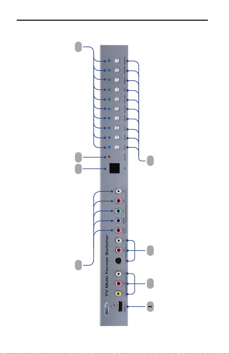
Front Panel
5
7
Page 9

ANEL LAYOU
T
l
1
4
6
8
3
Back Pane
19
17 1
15 1
1
12 1
1
10
5
Page 10

ANEL DESCRIPTION
S
R
uded
r
C
s
ess
ese buttons to selec
desired source
s
y
y
t
Front Panel
HDMI In
onnect a Hi-Def source device to this port using an HDMI cable.
Composite / Audio In 1
onnect a Composite source to this input using 3x RCA cables.
S-Video / Audio In 1
onnect an S-Video source to this input using an S-Video cable and 2x RCA
les.
4 Component / Audio In 1
onnect a Component source to this input using 5x RCA cables.
5 I
ives IR commands from the incl
6 Powe
This LED indicator glows bright red when the switcher is connected to an A
lectrical outlet.
7 Source Selection Button
Pr
th
Source Selection Indicator
These LED indicators will glow bright blue to indicate the currently selected
.
t the
IR remote control unit.
.
9 480i / 576i De-interlace
Pressing this button de-interlaces the video signal. Improves standard defi nition
ources such as gaming consoles and broadcast television. This function onl
affects input resolutions of 480i or 576i.
0 Audio Dela
Pressing this button will apply a 150ms audio delay to the output audio signal.
This is useful for lip sync and when using surround speakers connected to an
A VR.
1 RS-232 Serial Por
onnects to the RS-232 control device. The TV Multi Format Switcher may be
witched remotely using this port.
2 Composite / Audio In 2
onnect a Composite source to this input using 3x RCA cables.
Back Panel
Page 11

ANEL DESCRIPTION
S
3
t
C
3 Component / Audio In 1
onnect a Component source to this input using 5x RCA cables.
4 S-Video / Audio In 2
onnect an S-Video source to this input using an S-Video cable and 2x RCA
les.
5 PC / Audio In
onnect a VGA cable to the DB-15 connector. Use a 3.5mm mini-stereo cable
to connect the audio source to the 3.5mm mini-stereo jack.
6 HDMI In 2
onnect a Hi-Def source device to this port using an HDMI cable.
7 HDMI In
onnect a Hi-Def source device to this port using an HDMI cable.
8 HDMI Ou
onnect an HDTV display to this port using an HDMI cable.
9 5V D
onnect the included 5V DC power supply to this power receptacle.
7
Page 12

IR REMOTE CONTROL
r
C
3
(CO1)
(CO2)
e
254
4
ayout and Descriptions
LED Indicato
This LED will be activated momentarily each time a button is pressed.
CV1, CV2
elects the Composite 1 (CV1) or Composite 2 (CV2) input.
P
elects the VGA input.
4 HD1, HD2, HD
elects the HDMI 1 (HD1), HDMI 2 (HD2), or HDMI 3 (HD3) input.
5 CO1, CO2
elects the Component 1
or Component 2
input.
6 SV1, SV2
elects the S-Video (SV1) or S-Video 2 (SV2) input.
NOTE: An Activity Indicator that fl ashes quickly while holding down
any one of the 16 buttons indicates a low battery. Replace the IR
emote Control battery as soon as possibl
Page 13

IR REMOTE CONTROL
y
y
e
l
g
3:
:
y
t
):
y
Installing the Batter
The Remote Control unit ships with two batteries. One battery is required for
operation and the other batter
emove the battery cover on the back of the IR Remote Control unit.
1.
2. Insert the included battery into the open battery slot. The positive (+) sid
of the battery should be facing up.
.
is a spare.
emote Channel 1
1 2ON1 2
ON
1 2
Battery slo
hannel 0 (default
ON
1 2
emote Channel 2:emote Channel
ON
1 2
Setting the IR Channe
The IR channel on the IR Remote Control must match the IR channel used by the
V Multi Format Switcher. For example, if both DIP switches on the IR Remote
ontrol unit are set to IR channel 0 (both DIP switches down), then the TV Multi
Format Switcher must also be set to IR channel 0.
on how to chan
e the IR channel on the
WARNING:
type Dispose of used batteries according to the instructions.
isk of explosion if battery is replaced by an incorrect
V Multi Format Switcher.
ee page 12 for information
Page 14

g
:
k
.
CONNECTING THE TV MULTI FORMAT SWITCHER
How to Connect the TV Multi Format Switcher
onnect the HDMI output on the TV Multi Format Switcher to the display
sing the supplied HDMI cable.
2.
onnect up to three HDMI sources to the HDMI inputs.
.
onnect analog audio/video sources to the TV Multi Format Switcher usin
the following cables
•
2) 5 x RCA Component video cables to the Component inputs.
•
2) 3 x RCA Composite video cables to the Composite inputs.
•
1) VGA cable to the DB-15 connector.
•
1) 3.5mm mini-stereo cable to the 3.5mm mini-stereo jac
4.
onnect the included 5V DC power supply to the power receptacle on the
TV Multi Format Switcher
.
onnect the AC power cord to the power supply and connect the power cord
to an available electrical outlet.
The TV Multi Format Switcher is now powered and ready for use.
Wiring Diagram for the TV Multi Format Switcher
COMPOSITE VIDEO CABLE
ANALOG AUDIO (MINI STEREO) CABLE
ANALOG AUDIO (RCA) CABLE
COMPONENT CABLE
HDMI CABLE
VGA CABLE
S-VIDEO CABLE
RS-232 CABLE
HD Display
EXT-TV-MFS
Composite Source
Composite Source
S-Video Source
Component
Source
S-Video Source
VGA Source
Component
Source
Hi-Def
Source
Hi-Def
Source
Hi-Def
Source
RS-232 Controller
10
Page 15

1
OPERATING THE TV MULTI FORMAT SWITCHER
e
:
t
t
1
1
2
2
2
2
CPC /
n
1
1
1
1
2
2
2
2
1
1
3
3
p
a
p
d
Selecting the Input Sourc
• To select an input source, press any one of the front panel buttons. In the
xample below, the HDMI1 button has been pressed.
LED indicates that HDMI In 1
is the current input source.
Each button corresponds to a different input on the switcher, as follows
Button Inpu
V
V
V
V
omp
omposite In
omposite In
-Video
-Video
omponent In
Button Inpu
omp
P
DMI
DMI
DMI
omponent In
Audio I
DMI In
DMI In
DMI In
• The included IR Remote Control can also be used to select an input source.
Each button on the IR Remote Control corresponds to a button on the front
anel of the switcher. In the example below, Component In 2 has been
elected by pressing the CO2 button on the IR Remote Control.
LED indicates
button was presse
1
Page 16

OPERATING THE TV MULTI FORMAT SWITCHER
l
follows
f
S
gp
0
1
2
3
Setting the IR channe
After the TV Multi Format Switcher is powered, press and hold the CV1 and
V2 simultaneously. After a few seconds, the power LED will begin to fl ash
apidly.
2. The current IR channel will be indicated by the CV1 and CV2 buttons on
the front panel. In the illustration above, both LED indicators for CV1 and
V2 are not on. This indicates that the TV Multi Format Switcher is set to IR
hannel 0. IR channel 0 is the default setting.
.
onsecutively press the SV1 button will cycle through each IR channel, as
.
Flashing power LED
IR channel
IR channel
A
ter the SV1 button is pressed once, the power LED will glow solid red to
indicate that the IR channel on the
IR channel
IR channel
witcher has changed.
12
Page 17

3
OPERATING THE TV MULTI FORMAT SWITCHER
nce the TV Multi Format Switcher is set to the correct IR channel,
imultaneously press and hold the CV1 and CV2 buttons to reboot the
witcher. All of the front panel LED switching indicators will glow bright blue
momentarily, after which the Switcher will be ready for use.
IMPORTANT: The IR channel on the
match the IR channel used by the IR Remote Control Unit. See
age 12 for information on how to change the IR channel on the IR
emote Control Unit.
must
1
Page 18

4
RS-232 SERIAL CONTROL
0
8
e
1
e
feed
uded a
eac
ot
case-sensitive.
54321
9876
Only Pins 2 (RX), 3 (TX), and 5 (Ground) are used on the RS-232 serial interface
RS232 Settings
Bits per second ................................................................................................... 960
Data bits ....................................................................................................................
Parity .................................................................................................................. Non
top bits .....................................................................................................................
Flow Control ....................................................................................................... Non
12345
6789
IMPORTANT: When sending RS-232 commands, a carriage return
nd a line
ommands are n
haracter must be incl
t the end of
h line.
1
Page 19

e
ds
ds
0
1
ON
ON
SOURCE 0
1
1
SOURCE 1
2
2
SOURCE 2
3
3
SOURCE 3
C
n
SOURC
1
o
1
SOURCE 5
2
o
2
SOURCE 6
1
o
1
SOURCE 7
2
o
2
SOURCE 8
1
/
1
SOURCE 9
2
2
F
1
ON
A
ON
0
ON
ace
1
sable de
ace
1
uet s
R
e
SOURCE
t
g
80i/576
/
g
R
VERSIO
on
RS-232 COMMAND
S
Commands
Command RS-232 return valu
ELP Lists all comman
POWER
POWER
AUDIODELAY 0AUDIODELAY OF
AUDIODELAY
SD_ITOP
SD_ITOP
RESET
AUDIODELAY AUDIODELAY [ON /
SD_ITOP4
FW_VE
E 4
POWE
POWER OFF Power OFF
POWER
RCE HDMI
RCE HDMI
RCE HDMI
RCE P
RCE COMP
RCE COMP
RCE SV
RCE SV
RCE CV
RCE CV
AUDIODELAY
480i/576i to
480p/576p
480i/576i to
480p/576p OFF
no val
POWER [ON / OFF] The current power stat
URCE [Input] The active inpu
FF]
i to
576p [ON / OFF]
480p
FIRMWARE
N: [version]
escription
Lists all comman
Power
witch to HDMI In
witch to HDMI In
witch to HDMI In
witch to PC / Audio I
witch t
omponent/Audio In
witch t
omponent/Audio In
witch t
-Video/Audio In
witch t
-Video/Audio In
witch to Composite
Audio In
witch to Composite/
Audio In
Audio delay OFF
udio delay
Enable de-interl
Di
to default settings
Audio delay settin
De-interlacer settin
The current fi rmware
-interl
witcher
versi
r
r
15
Page 20

6
RACK MOUNT INSTALLATIO
N
ocate
ocated closes
.
ppp
ack mount ears are provided for installation of this unit into a 1U rack mount
.
1. L
2.
.
4.
the side screws on the unit.
move the front 2 screws that are l
sing the removed screws, screw the rack mounting bracket into the unit
Rear of unit
t to the front of the unit.
Front of unit
4
1
Page 21

SPECIFICATION
S
z
O
e
e
(2) C
)
e
e
k
C
)
)
g)
aximum Pixel Clock .............................................................................. 225 MH
Video Amplifi er Bandwidth ....................................................................... 350 MHz
Video
Video Input Connectors ........................................ (3) HDMI Type A 19-pin, femal
(2) Composite, RCA
(1) HD-15, femal
Analog Audio Inputs .............................. (2) L+R RCA, (1) 3.5mm stereo mini-jac
Power Supply .................................................................................... 5V / 2.6A D
Power Consumption ............................................................................ 13W (max.
Dimensions (W x H x D) ............... 17.3’’ x 1.8’’ x 6.3’’ (439mm x 45mm x 160mm
utput Connector ..................................... (1) HDMI Type A, 19-pin, femal
omponent (3x RCA
-232 Remote Control Port............................................................. DB-9, femal
ack Size .......................................................................................................... 1U
hipping Weight ............................................................................... 8 lbs. (3.6 k
17
Page 22

8
efen warrants the equipment it manufactures to be free from defects in material
f
y
N
.
and workmanship.
I
equipment fails because of such defects and Gefen is notifi ed within two (2)
ears from the date of shipment, Gefen will, at its option, repair or replace the
quipment, provided that the equipment has not been subjected to mechanical,
lectrical, or other abuse or modifi cations. Equipment that fails under conditions
other than those covered will be repaired at the current price of parts and labor in
ect at the time of repair. Such repairs are warranted for ninety (90) days from
the day of reshipment to the Buyer.
This warranty is in lieu of all other warranties expressed or implied, including
without limitation, any implied warranty or merchantability or fi tness for any
articular purpose, all of which are expressly disclaimed.
1. Proof of sale may be required in order to claim warranty.
2.
ustomers outside the US are responsible for shipping charges to and from
efen.
.
opper cables are limited to a 30 day warranty and cables must be in their
original condition.
The information in this manual has been carefully checked and is believed to
be accurate. However, Gefen assumes no responsibility for any inaccuracies
that may be contained in this manual. In no event will Gefen be liable for
direct, indirect, special, incidental, or consequential damages resulting from
any defect or omission in this manual, even if advised of the possibility of such
damages. The technical information contained herein regarding the features and
pecifi cations is subject to change without notice.
For the latest warranty coverage information, refer to the Warranty and Return
Policy under the Support section of the Gefen Web site at www.gefen.com.
RODUCT REGISTRATIO
lease register your product online by visiting the Register Product page
nder the Support section of the Gefen Web site
1
Page 23

Page 24

1
800-545-6900
0
m
Rev A
9
1-
www.gefen.com support@gefen.co
This product uses UL or CE listed power supplies.
Nordhoff St., Chatsworth CA 9131
818-772-9100 fax: 818-772-912
Pb
 Loading...