

Page 1

®
CS
w
Professional
Automatio
ontrol System
EXT-PA
r Manual
w.gefen.com
Page 2

Page 3

ASKING FOR ASSISTANC
E
t
0
0
0
:
:
C
e
0600
1
e
C
©
d
3
66
echnical Suppor
Telephone (818) 772-910
(800) 545-690
Fax (818) 772-912
echnical Support Hours
:00 AM to 5:00 PM PST Monday thru Friday.
Write To
efen, LL
o Customer Servic
2
Nordhoff St
hatsworth, CA 9131
www.gefen.com
upport@gefen.com
Notic
efen, LLC reserves the right to make changes in the hard ware, packaging and
any accompanying doc u men ta tion without prior written notice.
rofessional Automation Control System is a trademark of Gefen, LL
All trademarks are the property of their respective companies.
2012 Gefen, LLC, All Rights Reserve
All trademarks are the property of their respective companies
Rev A
.
Page 4

CONTENT
S
oduction
yout
t
CS
CS
face
5
u
CP /
9
u
e
e
u
u
n
e
t
(
p
Confi g
n
p
y
x
2
t
y
1 Intr
2 Operation Notes
Features
4 Front Panel La
Front Panel Descriptions
Back Panel Layou
7 Back Panel Descriptions
Connecting the PA
Wiring Diagram
Confi guring the PA
14 Web Inter
14 The Built-in Web Server
RS-232 Men
1
16 RS-232 Settings
17 T
IR Emitters Men
1
24 Adding a new IR devic
28 Adding a new IR device from a Templat
2 Triggers Men
4 Testing Triggers
5 Confi guration Men
5 IP Confi guratio
7 Telnet Login Settings
8 Firmware Updat
9 System Rese
41 System Settings
43 IP
45 RS-232 / Telnet Commands
45 IP
77 General Quer
Telnet) Control Setu
8 Bridging Settings
5 IR Device Setu
0 Appendi
0 Controlling the PACS via RS-23
1 Learning IR Commands via Telne
3 Specifi cations
4 Warrant
UDP Bridge Settings
uratio
Page 5

m
CS)
f
y
e
o
ffere
ufacturers
t
INTRODUCTIO
N
ongratulations on your purchase of the Professional Automation Control
stem. Your complete satisfaction is very important to us.
efen
efen delivers innovative, progressive computer and electronics add-on solutions
that harness integration, extension, distribution and conversion technologies.
efen’s reliable, plug-and-play products supplement cross-platform computer
stems, professional audio/video environments and HDTV systems of all sizes
with hard-working solutions that are easy to implement and simple to operate.
he Gefen Professional Automation Control Syste
The Professional Automation Control System (PA
efen devices using RS-232 or IR, and other A/V devices (displays, Blu-ra
layers, cable/satellite boxes, lighting systems, motorized screens, etc.) from
any Web-enabled smartphone, WiFi tablet, laptop, or automation system.
The Web user interface allows IR, RS-232, and 12V trigger commands to b
ent by the PACS to the connected devices to execute the desired functions.
The confi gurable IR, RS-232, and 12V DC trigger signals allow the PACS t
be compatible with most A/V devices. The PACS can learn, store, and manage
IR commands of di
The 12V DC triggers are highly confi gurable to work with the differen
equirements of various devices.
se with the new Gefen A/V Automation System Processor to create a complete
ontrol system.
How It Works
onnect the serial-controlled devices to the PACS RS-232 ports. Plug the IR
mitters into the PACS and place the LEDs close to the IR sensors of the A/V
devices to be controlled. Connect trigger leads of various devices to the trigger
outputs on the back panel. Connect the locking power supply to the PACS.
onnect an Ethernet cable between the PACS and the local network.
Access the Web interface by typing in the correct IP address on your Web
browser (default: 192.168.1.72), or by using Telnet. Confi gure the control
interfaces (IR, RS-232, 12V DC triggers) via the Telnet/Web browser.
onfi gure the Automation System to send commands to the PACS via IP.
nt man
’ remotes.
allows IP control o
Page 6

G
M
y
ess
CS
f
m
OPERATION NOTE
S
READ THESE NOTES BEFORE INSTALLING OR OPERATIN
THE PROFESSIONAL AUTOMATION CONTROL SYSTE
• The PACS is shipped with a static IP address of
address ma
Area Network. See page 10 for instructions on setting the PACS to a new IP
r
• If your network will contain multiple PACS units, each one must have a
nique IP address before it is connected to the network. Install one PA
at a time, and change its IP address before connecting another PACS to the
twork.
• As the PACS is programmed, you can download the confi guration and IR
les to your computer or an external storage device. We recommend that
ou back up fi les frequently during programming, and save IR fi les for each
device as it is learned. These fi les can be transferred to another PACS for
uture projects.
•
-232 commands are not stored in the PACS. Only the confi guration data
is stored. The PACS acts as a bridge between your controller that is sending
the RS-232 commands over your network, and the actual RS-232 port on
the device that is being controlled.
• PACS allows control to be distributed throughout your system. Multiple
PACS devices may be installed close to the devices being controlled, rather
than near the system controller, to minimize cabling and improve reliability.
need to be changed before the PACS will work on your Local
.
RS-232 Port Wiring Diagra
.168.1.72 This
54321
9876
Only Pins 2 (RX), 3 (TX), and 5 (Ground) are used on the RS-232 serial interface
12345
6789
Page 7

y
C
)
y
e
FEATURE
S
Features
•
ontrol AV devices using IR, RS-232 control, and 12V triggers over a Web
based IP control s
onfi gurable Ethernet input supports Telnet, Web browsers, and TCP/IP.
•
• Web Control: User interface designed to be viewed and controlled by home
automation devices, computers, and mobile devices (i.e. cell phones with
Internet browsers).
• 10 Trigger outputs (+12V, fl oating, open drain, or ground-referenced).
• Learns IR commands from manufacturer remotes, through front-panel IR
eceiver. Learned IR fi les may be saved on or retrieved from the user’s P
in XML format.
•
tore and manage IR commands from manufacturer remotes and access
them via the Web control interface or TCP/IP Telnet.
• Eight discrete IR Emitter outputs for multiple device control.
•
anage RS-232 communications via Web control interface for up to three
-232 devices. Supports baud rates up to 115200.
• Firmware can be upgraded via Web interface.
stem.
•
ack-mountable using the 1U Rack Tray (Gefen part no. EXT-RACK-1U).
ackage Includes
1) Professional Automation Control System
4) Single IR emitters
1) 6 ft. DB-9 cable (M - F
1) 12V / 3A DC Locking Power Suppl
1) Quick-Start Guid
Page 8

FRONT PANEL LAYOU
T
Front Panel
Page 9

s
P
f
ocated o
r
FRONT PANEL DESCRIPTION
S
The IR receiver is provided for the PACS to learn new IR commands. Use
the Web Interface or Telnet for this procedure. See pages 17 - 23 for more
information.
tatu
This LED indicator is normally OFF. It glows bright blue when the PACS is
eady to receive a new IR command via the IR receiver.
eset I
This button is used to reset the IP address of the PACS. Hold this button down
or about 10 seconds, until power light turns red, to reset the unit’s IP address to
192.168.1.72
r cannot be l
owe
This LED will indicate the current power state. The LED is green when the unit
is powered ON. The LED also fl ashes red during the Reset IP procedure.
This should only be done if the PACS is moved to a new network
n the network.
5
Page 10
BACK PANEL LAYOU
T
l
5
Back Pane
Page 11
BACK PANEL DESCRIPTION
S
C
)
f
s
s
n
“G
s
f
ot
be used with
12V D
onnect the included 12V DC locking power supply to this receptacle.
IP Control
onnect the PACS to a network in order to use IP control.
RS-232 Serial Ports (DB-9, male connectors
These ports are used to control other devices via bi-directional RS-232 serial
ontrol, using TCP or UDP bridging. Port 3 may also be used with a Terminal
Emulation program for programming and controlling the PACS (See Appendix
or details).
NOTE: Only pins 2 (Receive), 3 (Transmit), and 5 (Ground) are used
or communication. A null-modem adapter should n
this product when connecting to controlled devices (see page 80 for
onnecting to a computer via RS-232).
4 IR Emitter
onnect up to eight (8) single or dual 12V IR emitters (Gefen part no.
EXT-IREMIT or other Xantech-compatible emitters) to these ports to control
A/V or other devices using one-way IR control. These outputs are capable of
transmitting IR signals with 30 - 60 kHz carrier frequencies.
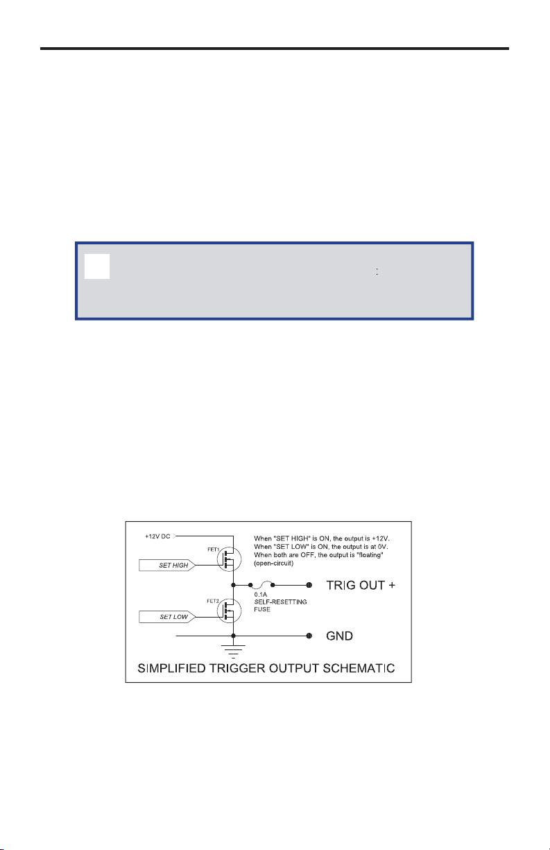
5 Phoenix (Euroblock) Trigger Connector
onnect up to ten (10) 12 Volt-controlled device inputs to these solid-state
trigger outputs to control screens, drapes, lights, or other devices. Maximum
ource current is 100 mA per output. Use a 12V DC relay with less tha
100 mA current draw to control other devices. Connect trigger wires to
emovable terminal block plugs.
6 Phoenix Terminal Block Plug
Each trigger has a solid-state (FET) output that can be confi gured as either
ush-pull (+12V or 0 V reference to the “G”-terminal) or open collector (either
open circuit or connected to the
”-terminal). Each output can source up to
100 mA at 12V DC.
7
Page 12
S
S
CONNECTING THE PAC
S
How to Connect the PAC
1.
onnect up to three (3) RS-232 (M-F) cables between the PACS and each of
the RS-232 devices.
onnect up to eight (8) single or dual IR Emitters to the PACS. Make sure
2.
that each LED emitter is close to the IR sensor of the A/V devices to be
ntrolled.
.
onnect the trigger leads of each of the various devices to the trigger
outputs on the back panel of the PACS.
4.
onnect an Ethernet cable between the PACS and the network. See the
ext page for details on confi guring the network.
.
onnect the included 12V DC power supply to the power receptacle on the
PACS. Connect the AC power cord to an available electrical outlet.
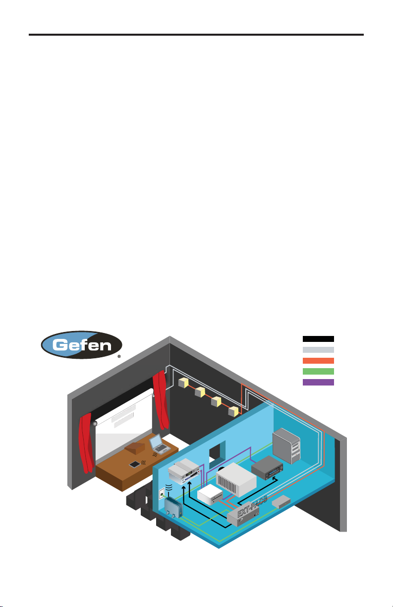
Wiring Diagram for the PAC
POWERED CURTAINS
POWERED
SCREEN
RS-232 CONTROLLED LIGHTING
HDMI DEVICES
IR BLASTER
ROUTER
IR BLASTER
12V/GND TRIGGERS
GEFENTV
HDMI 4x1 +
RS-232
PROJECTOR
T A
IR PORT
RS-232
IP / RJ-45
HDMI
PC
A/V REC.
IR BLASTER
EXT-GAVA
EXT-PACS
Page 13

P
defau
address
C
ffere
each u
d
CONFIGURING THE IP ADDRES
S
Setting the IP Address
The PACS is designed to control devices over a network using a built-in Web
erver or via Telnet. Before using Telnet control or the built-in Web Server, the
etwork settings for the PACS must be confi gured via IP.
Before connecting the PACS to a network, locate the label on the bottom of the
PACS. The MAC address and the default IP address will be listed on the label.
The default IP address will be used to connect the PACS to the network.
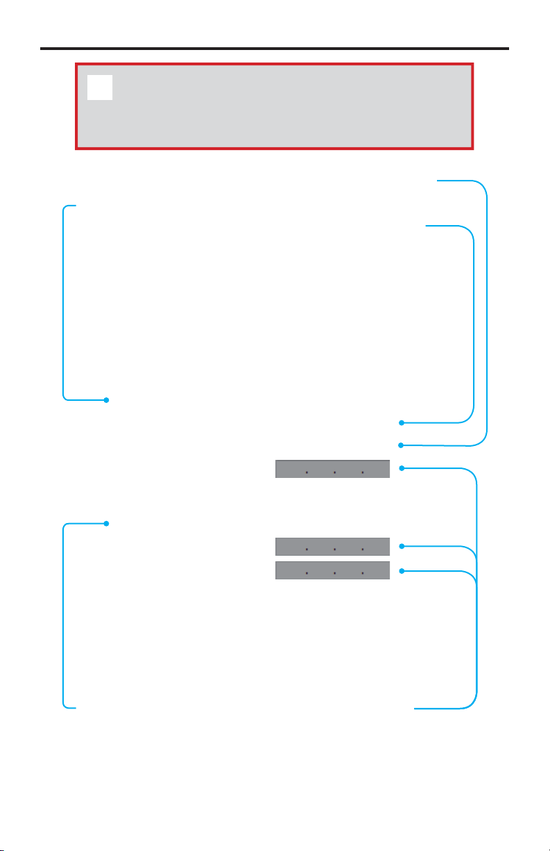
IMPORTANT: Because all PACS units have the same default IP
address, only one PACS may be connected to a network at a time,
ntil its IP address is changed. If more than one device with the
ame IP address is connected to a network, computers will be
nable to locate any of the devices.
A
Primary MAC address of
the PACS. This address is
i
nt for
annot be changed.
nit an
I
The
of the PACS.
lt IP
Page 14

:
s
g:
CONFIGURING THE IP ADDRES
S
If you computer has an IP address of
an available address, you can access the PACS by entering
our Web browser.
therwise use the following procedure to change the PACS IP address to match
our network
1. Access the Network Setting control panel in Windows and locate your LAN
onnection. Under Windows 7®, this can be done by clickingtart > Control
anel > Network Sharing Center > Change Adapter Setting
2.
lick on the Local Area Connection icon to display the Local Area
onnection Status dialo
.168.1.(x), and
.168.1.72 is
.168.1.72 in
10
Page 15

1
/
CONFIGURING THE IP ADDRES
S
)
.
lick on the Properties button to display the Local Area Connection
Properties dialog.
lick on Internet Protocol Version 4 (TCP/IPv4).
4.
Internet Protocol Version 4 (TCP/IPv4
lick to highlight this Network protocol.
.
lick the Properties button to display the Internet Protocol Version 4 (TCP
IPv4) Properties dialog.
1
Page 16
CONFIGURING THE IP ADDRES
S
g:
address
used address
t
ess
9
80*
0
S
STOP: Write down the current IP settings before making changes,
ince you will need to restore the old settings later. If the Properties
are set to “Obtain an IP address automatically” and “Obtain DN
erver address automatically”, you do not need the actual address
ettings.
.
hange the IP settings to the followin
se the following IP address
lick this radio button.
Subnet mask
255.255.255.
IP address
2.168.1.
1
se the following DNS server addresses
lick this radio button.
If the IP
nother un
.168.1.80 is already in use on your network, choose
that isno
lear these boxes.
.168.1.72 or your router’s IP
r
12
Page 17

3
CONFIGURING THE IP ADDRES
S
CS
ffere
address
7.
lick the OK button, then close all Control Panel windows.
.
efresh your Web browser and go to
PA
Web Server.
.
o to the Confi guration Menu (see page 35) and change the PACS IP
address to an appropriate address for your network.
10.
lick ”Save Changes”, “Reboot”, and “OK” to save the new IP address.
11.
eopen your computer’s network settings and restore the original settings
or go back to “Obtain an IP address automatically” and “Obtain DNS server
address automatically”, if those were the original settings).
12. Then refresh your Web browser and go to the new PACS IP address to
eopen the PACS Web Server.
epeat this procedure to add additional PACS units to your network, assigning
h unit a di
nt IP
.
ttp://192.168.1.72 to open the
1
Page 18
4
WEB INTERFA
CE
f
fi g
t
u
he Built-in Web Server
The PACS includes a built-in Web server which provides an intuitive Web
inter
ace. If TCP/IP is not confi gured on the PACS, then see page 9 for details
on con
then open a Web browser and type in the IP address of the PACS.
The built-in Web server provides control over RS-232, IR emitters, triggers,
and general confi guration. Each of these pages will be covered in the following
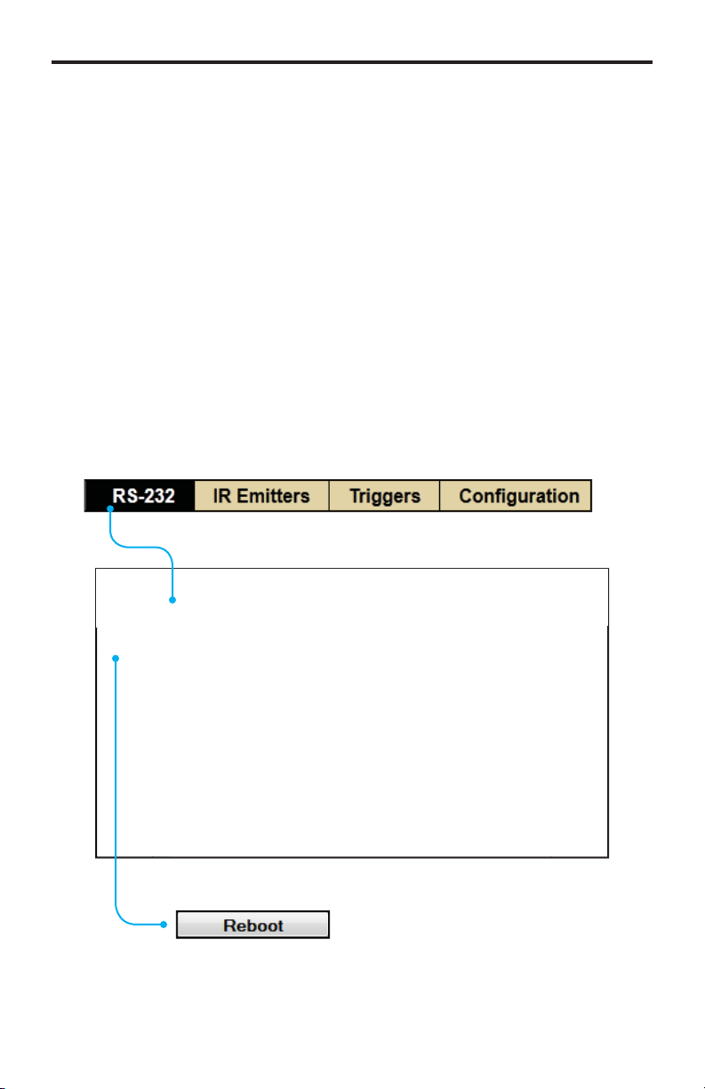
Initially, when the Web page is launched, the RS-232 Menu is displayed. The
top portion of the screen has tabs to select RS-232 settings, IR settings, trigger
ettings, and general confi guration. Click on the desired tab to bring up the
ettings page for those functions.
uring the PACS. If the PACS is already confi gured for use on a network,
tions.
ain Menu
lick on any of the four men
elections to access the desired page.
Reboo
The PACS must be rebooted after making all
hanges.
1
Page 19
WEB INTERFA
CE
S
ce
t
)
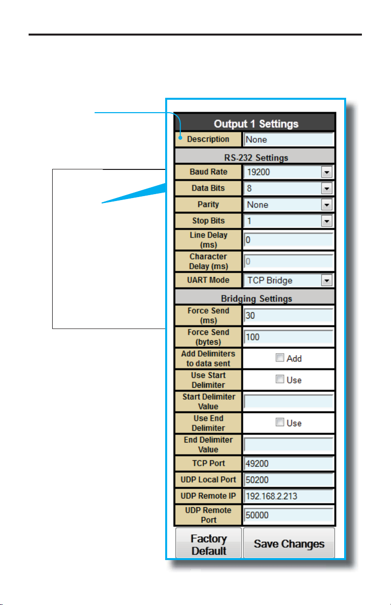
RS-232 Menu
The PACS has three (3) RS-232 ports. The RS-232 Menu allows you to change
the R
-232 port settings on the PACS.
escription
Provide a name to the devi
onnected to this por
e.g. “SonyTV”, “Samsung”, etc.
Page 20
6
WEB INTERFA
CE
s
:
e
y
e
e
ge
)
y (ms)
used
-232 Setting
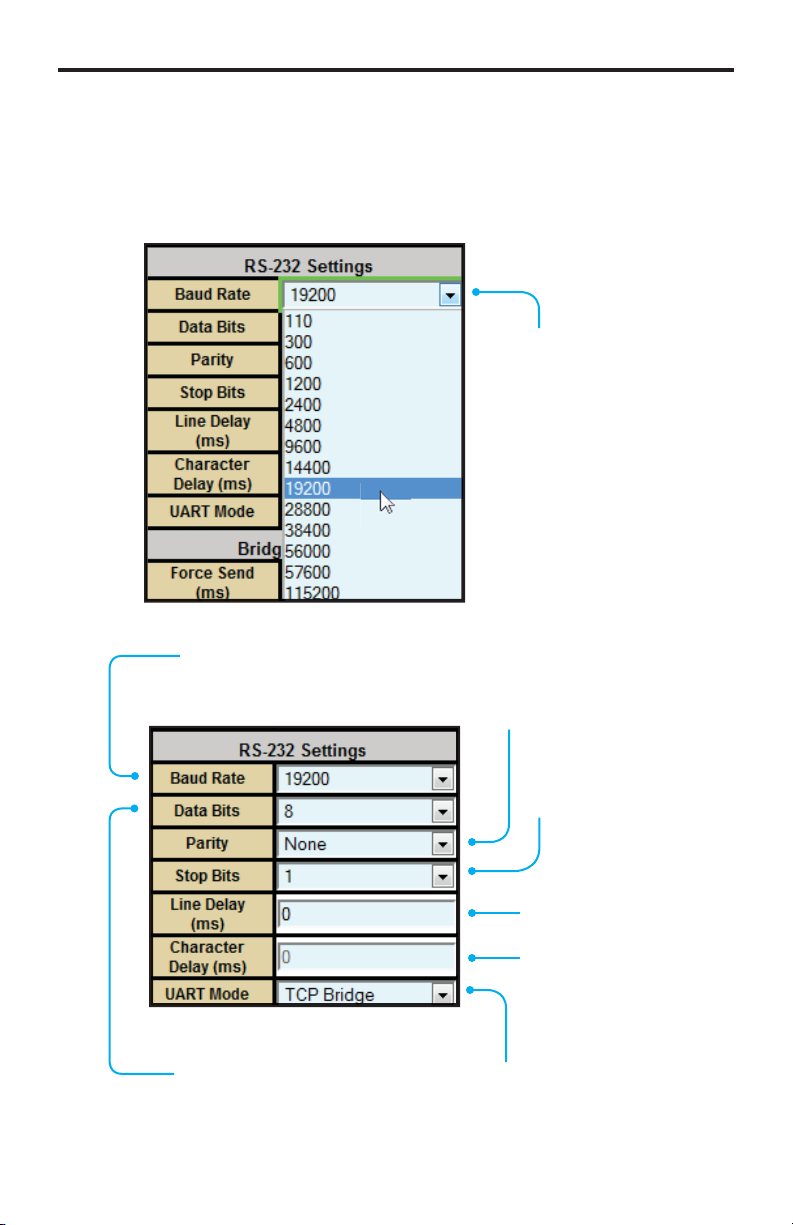
ome RS-232 settings use a drop-down menu for selecting different options.
For example, to select the Baud Rate, click the arrow icon then click on the
equired port speed
Arrow Icon
Indicates a dropdown list. Click to
ist the available
rates.
Baud Rat
ets the baud rate for the port.
ange: [100 bps - 115200 bps]
ata Bits
ets the number of data bits.
ange: [5 - 8]
arit
ets the parity bit.
ptions: Even, Odd,
None, Mark, Spac
Stop Bits
ets the stop bit.
ange: [1 - 2]
ine Delay (ms
ange: [0 - 10000]
Character Dela
Not
ART Mod
ptions: TCP Bridge, UDP
Brid
.
1
Page 21
WEB INTERFA
CE
s
f
g
f
)
eceived fro
(by
)
V
X
t
)
)
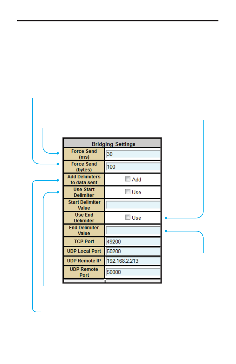
P / UDP Bridging Setting
DP Protocol is used by some control systems, including Gefen’s GAVA system,
or faster response. When using UDP you can broadcast the message by usin
the IP address: 255.255.255.255. Use TCP unless otherwise instructed by your
ontrol System User Manual, or by Gefen Technical Support. See page 58 for a
ull explanation of these settings.
Force Send
If the specifi ed number of bytes is received from the controlled device, send
the collected data to the control system.
tes
Force Send (ms
If no data is r
device for the specifi ed time, send the
ollected data to the control system.
m the controlled
se End Delimiter
ptions: Use
Enable / Disable
nd Delimiter
alue in HE
ange: Same
as Start Delimiter
se Start Delimiter
ptions: Use (Enable / Disable
Add Delimiters to data sen
Include the delimiter characters in the data sent to the control system.
17
Page 22
8
WEB INTERFA
CE
s
t
5
P
t
5
t
d
g
#
5
X
**)
f
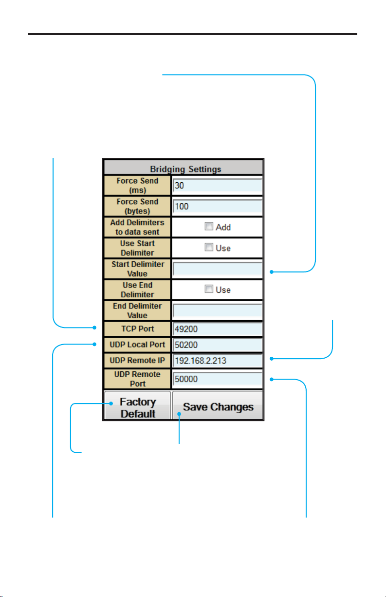
P / UDP Bridging Setting
Start Delimiter Value in HE
ange: 00 - FF (“wildcard” characters are acceptable, e.g.
The Start Delimiter can be up to three ASCII characters (3 bytes), in hex
ormat. For example, 0D0A is CR + LF (Carriage Return + Line Feed).
The delimiters are used by some control systems to fi lter incoming data.
ontact Gefen Technical Support for details if you need to use them.
CP Port
ange: 0 - 6553
DP Remote I
Factory Defaul
ets the selecte
-232 port to factory
default) settings.
DP Local Por
ange: 1024 - 6553
Save Chan
aves all changes to the
elected RS-232 port. This
button must be pressed after
hanging
order to save any changes.
es
ach output setting. in
DP Remote Por
ange: 1024 - 6553
1
Page 23

WEB INTERFA
CE
y
e
ces
e
ces
e
dds a device to
s
e
e
IR Emitters Menu
The PACS has eight (8) IR Emitter (IR back-channel) ports. The PACS can use
an
one of these IR Emitter ports to send IR commands to the source device.
p to 64 IR commands can be stored per device. IR confi guration fi les can be
aved, downloaded, uploaded, edited, and deleted.
Select Outputs To Test Commands
List of IR Emitter output ports used to test the IR commands.
Add Devic
A
action must be performed before
earning a device.
the list. Thi
Select Devic
List of devi
been stored in the PACS.
The PACS can store up to 20
vi
.
Rename Devic
enames the currently selected
vice in the list.
elete Current Devic
Deletes the currently selected
vice from the list.
19
which hav
Page 24

WEB INTERFA
CE
e
h
spaces
t
ess
o
w
ced
Command Nam
sed to enter / edit the name of eac
IR command. This is a required fi eld.
p to sixty-four (64) IR commands can be
tored per device. Each Command Name
an be up to 20 Alphanumeric characters
.
Advanced Vie
lick this link to toggle between
Basic View and Advan
View.
es
Pr
the Test button t
validate the learned IR
ommand. One or more
outputs must be selected and
an IR Emitter plugged in before
test can be sent.
0
Page 25
WEB INTERFA
CE
A
w
k
f
g
a
ge
e
e
e
y
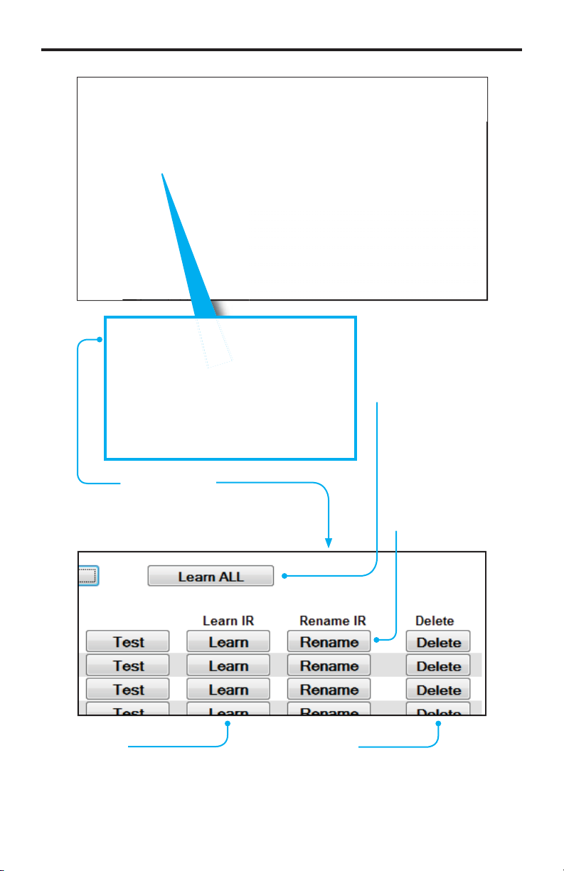
earn All
Performs a “stepthrough” when learnin
IR commands from
template (see pa
28).
dvanced Vie
lick the Advanced View lin
to display additional options
or learning or deleting IR commands.
earn
lick the Learn button to learn a
ew IR command (see page 22).
elet
lick the Delete button to delete
learned IR command. Deleted
ommands will be permanentl
emoved after saving changes.
Renam
lick the Rename
tton to renam
the IR command.
Page 26

WEB INTERFA
CE
e
y)
)
)
l
)
odel No. (optiona
This is the device model number (e.g. KDL40EX729, etc.
This fi eld is used by the GAVA to sort the IR library.
ax. Length: 15 characters (letters, numbers, and
nderscores only).
anufacturer (optional
This is the device manufacturer’s name (e.g. Sony,
Yamaha, etc). This fi eld is used by the GAVA to sort
to the IR library. 15 characters (letters, numbers, and
nderscores only).
Class (optional
This is the generic class of the device: Display, Disc, AVR
A/V Receiver), or STB (Set-Top Box). This fi eld is used
by the GAVA to select the proper control template.
15 characters (letters, numbers, and underscores only).
Nam
This is the Device Name of the currently-displayed device. Click the
Rename Device” box to rename the current device. Max. Length: 20
haracters (letters, numbers, or underscores onl
2
Page 27

WEB INTERFA
CE
D
g
t
.
w
se..
lick this button to open a list of fi les on
our computer to Upload. It will open the
ast selected folder on your computer with a
ownload IR File to PC
Press this button to save the currently-displayed Device IR
ommands to an XML fi le on your computer. Choose a folder
ocation and fi lename that will allow you to easily locate the fi le at a
ter time.
Save Chan
Press this button to save any changes to the currently-displayed Device.
Be sure to press “Save Changes” before navigating away from this page
or selecting another Device, or your changes will be los
es
evice I
The PACS assigns an internal number to each Device in memory. You
an use this number to keep track of the number of Devices you have
tored in the PACS.
default selection of All Files (*.*).
Bro
Page 28

WEB INTERFA
CE
e
C
f
ess “
y
e
y
fi
Adding a new IR Devic
The PACS can hold up to 20 IR devices in memory. Each device may have up
to 64
ommands. If you are building a library, you may need to delete some
devices
devices. However, if you have several of the same devices with separate IR
mitters, you can use the same IR “Device Name” for all of them, but specify a
different output for each one when you send the commands.
Be sure to “Save Changes” after learning any new commands before navigating
away from the learning page.
rom the PACS once they are learned and saved, to make room for more
1. Pr
2. If you have an existing Iearned IR code fi le, or wish to download an empt
. Enter a Name for the new device. The name can be up to 20 characters
4. Enter the Class, Manufacturer, and Model Number of the device (optional).
.
.
7. If the IR commands were already learned for that device, the Command
. If a blank template was stored for that device, the Command Names will
Add Device” button on PACS IR Emitters page.
ommand Name template for the new device, click the “Browse” button, and
avigate to the location on your computer where the IR fi les and templates
are located. Select the desired “*.gfn” fi le and click “Open”. Otherwise, skip
to Step 8.
ong, and will be used to identify the device for sending IR commands.
lick “Save Changes” to store the fi l
elect the stored device from the “***Select Device **** pull-down menu.
Names will be green, and the commands may be tested by installing an
IR Emitter in front of the device’s IR window, connecting the emitter to an
IR Output port on the PACS, selecting that Output in the Web browser,
and clicking on the “est” button for that command. Verify that the device
esponds as expected.
appear, but they will be yellow, rather than green. This means that onl
the names, and not the IR data, have been stored. See “Adding a New IR
Device from a Template” on page 28.
. If you are starting a new device fi le, the Command Names will be empty, and
the
elds will be light blue. Click on the fi rst empty Command Name window,
and enter a name for the command (note that only letters, numbers, and
paces can be entered. Spaces will be replaced with underscores when the
le is saved). The Command Name and Device Name are case-sensitive.
10.
lick on the “Advanced View” button above the Command Name list. This
the “earn” and “elete” buttons for each Command.
Page 29

WEB INTERFA
CE
fou
10. Find the IR remote for the new device. Make sure the batteries are fresh!
old the remote so it is pointing at the IR window on the PACS, and is about
” away from the window.
lick the “earn” button for the fi rst named Command.
11.
12. You will be prompted to press the remote button that matches the Command
Name you are learning. Press the button fi rmly- do not hold it down, or just
it it quickly.
Please have your remote control and get ready to press the remote key...
Learning IR MODE Enabled:
Please press the 1 button.
Please press the 1 button again.
13. You will be prompted to press the same button a second time. The PACS
will confi rm that the two codes match. Some IR remotes use “toggle codes”,
where the IR code toggles between two different codes each time the button
is pressed. The PACS will recognize this, and ask you to press the button a
third and
rth time.
Learning IR MODE Enabled:
Please have your remote control and get ready to press the remote key...
Please press the 4 button.
Please press the 4 button again.
1st and 2nd command captures were not identical, please press the 4 button
with your remote.
Please press the 4 button again.
Page 30

WEB INTERFA
CE
5
CS
add a new command and re-lea
code
ess “
e
ess “
o
14. If the commands match, the PACS will return to the main screen, and the
ew command will now be green.
1
.If a code is learned incorrectly, you may overwrite it by repeating steps
11 - 13. The PA
and ask you to confi rm that you want to overwrite the existing code. Press
OK” to do so. Once a Command is learned, its Command Name may not
be changed. If the name is incorrect, you must delete the Command Name,
nd
ADVANCED: If you are familiar with editing XML fi les, you can
download the Confi g fi le, edit the XML fi le, and upload it again to the
PACS. This is an advanced feature and not recommended for new
16. Learn each command in turn by repeating the “earn” procedure (after
ntering each Command Name if necessary).
will warn you that the command is already in memory,
rn the
.
.
17. Pr
18.Pr
ost! You can leave the page after saving changes, and return later to learn
19.
IR fi le to your computer and save it. Press the “ownload IR File button t
20.PACS will prompt to “Open” or “Save” the fi le. You probably should click
Open” to see and check the fi le before saving it. A sample XML fi le is
est” to verify that each command performs as expected (se
tep 6).
Save Changes” to save the learned Commands to the PACS. Be
ure to do this before navigating away from the page, or the changes will be
ew commands, or test/modify existing commands. All named commands
ust be learned before saving the changes. Command names that do not
ontain IR data will be deleted when changes are saved.
nce a new device has been learned, you should download the new device
this.
hown on the next page.
Page 31

WEB INTERFA
CE
280
ocation and fi lename fo
use
defau
fi
ess “
<?xml version=”1.0” encoding=”UTF-8”?>
<ir_emitter>
<dn>
edroom_DVD</dn>
<class>
<manufacturer>
<model>
<cs>
<c>
<cn>
<freq>
<p_len>
<p_dat>
<p_rep>
</c>
<c>
<cn>
<freq>
<p_len>
<p_dat>
<p_rep>
</c>
<c>
<cn>
<freq>
<p_len>
<p_dat>
<p_rep>
</c>
</cs>
</ir_emitter>
</class>
ony</manufacturer>
DPS580</model>
ower_toggle</cn>
175</freq>
4</p_len>
4 149 279 ... 149 137 5149 0</p_dat>
</p_rep>
ower_off</cn>
</freq>
4</p_len>
4 148
</p_rep>
olume_up</cn>
</freq>
4</p_len>
4 148 137 ... 137 5291 0</p_dat>
</p_rep>
... 136 5007 0</p_dat>
NOTE: The series of numbers contained within the opening and
losing <p_dat> tags have been abbreviated due to limited page
.
21. Verify that the commands contain data, and click “File > Save as . . .”,
nd enter a l
ir_emitter_xml.xml” fi lename, as it will overwrite earlier stored fi les. We
ecommend that you use a fi lename that contains the manufacturer name
and model number of the device, so you can easily identify the fi le later.
The maximum
22. Pr
23.
Save” to actually save the fi le to your computer
epeat the above procedure for each device you wish to add to the PACS.
lename size is 25 characters.
r the new fi le. Do not
the
7
lt
Page 32

WEB INTERFA
CE
e
ff
:
e
on
r
y
sc
)
b
)
:
ess “
Adding a new IR device from a Templat
Templates are useful when you want to ensure that similar commands for
di
erent product models have identical Command Names. This will simplify the
rocess of programming your control system, and allow you to replace one disc
layer, for example, with another model, without having to change the control
stem programming.
efen’s GAVA Control System requires that IR commands have specifi c name
onventions that are matched to the GAVA User Interface buttons, so Templates
rovide an easy way to ensure that new devices have the proper names.
sing a Template also allows you to just push buttons on your IR remote as
rompted, without having to simultaneously enter names and navigate the screen
on your computer.
PACS comes with several pre-confi gured templates for the Gefen GAVA control
stem, which are needed to build a GAVA Library. These correspond to the
different Classes of IR-controlled devices
Templat
v
displa
i
t
To add a new device, using a PACS Template File
1. Pr
2. Enter a Name for the new device. The name can be up to 20 characters
ong, and will be used to identify the device for sending IR commands.
.
ptionally, enter the device Manufacturer and Model Number.
4.
lick the “Browse button, and navigate to the location on your computer
where the IR templates are located. Select the desired “*.gft” fi le and click
Open
.
lick “Save Changes” to store the fi le.
.
elect the stored device from the “***Select Device **** pull-down menu.
Defi niti
Audio/Video Receiver or Amplifi er
Display, TV , Projector, or Monitor
Disc Player (Blu-ray, DVD, CD, Music Server
et-Top Box (Cable or Satellite Receiver
Add Device” button on PACS IR Emitters page.
.
Page 33

WEB INTERFA
CE
above
CS
gg
fou
.
ince this is a template fi le, the Command Names will be yellow, rather than
reen. This means that only the names, and not the IR data, have been
tored.
lick on the “Advanced View” button above the Command Name list. This
7.
the “earn” and “elete” buttons for each Command, and a button
med “earn ALL
. Find the IR remote for the new device. Make sure the batteries are fresh!
old the remote so it is pointing at the “IR” window on the PACS, and is
about 6” away from the window.
.
lick the “earn ALL
10. You will be prompted to press the remote button that matches the Command
Name you are learning. Press the button fi rmly- do not hold it down, or just
it it quickly.
11. You will be prompted to press the same button a second time. The PA
will confi rm that the two codes match. Some IR remotes use “toggle codes”,
where the IR code to
is pressed. The PACS will recognize this, and ask you to press the button a
third and
rth time.
.
button.
les between two different codes each time the button
9
Page 34

WEB INTERFA
CE
3
each command
bee
f
ess “
12. If the commands match, the PACS will prompt you for the next Command in
the list.
1
.If you are prompted for a command that does not exist on your remote,
ou can press the “SKIP Command” button, and you will be prompted for
the next button on the list, or you can press “XIT IR Learning to end the
rocess. If you start the Learn ALL process again, it will start with the fi rst
n-learned command, and skip any commands that have previously been
rned.
14. Learn
15. The learned command will now be green. Any commands that were skipped
16. You can manually add any commands that were not in the template
17. Pr
Please have your remote control and get ready to press the remote key for 1
or not learned successfully will still be yellow.
afterwards. Since commands are accessed by name, and not by number,
the sequence of learning commands is not critical. Commands that are
in the Template cannot be re-named. They can be deleted, and then new
ommands may be added at the bottom after saving the changes. There is
a maximum o
nused commands to create room for any new ones.
64 commands per device, so you may need to delete some
est” to verify that each command performs as expected.
AUTO IR Learning MODE Enabled:
Please press the 1 button.
in turn until all have
n learned.
0
Page 35

ose commands
be
9
ess “
ocation and fi lename fo
use
defau
ess “
WEB INTERFA
CE
18. You can delete any commands that are not available for that specifi c remote
by clicking the “elete” button for th
emoved when changes are saved. Un-learned template commands will be
aved for later learning.
. Deleted buttons will
.Pr
1
20.
21. PACS will prompt to “Open” or “Save” the fi le. You probably should click
22. Verify that the commands contain data, and click “File > Save as . . .”,
23.Pr
24.
Save Changes” to save the learned Commands to the PACS. Be
ure to do this before navigating away from the page, or the changes will be
ost! You can leave the page after saving changes, and return later to learn
ew commands, or test/modify existing commands.
nce a new device has been learned, you should click the “ownload
IR File to PC” button to download and save the new device IR fi le to your
omputer.
Open” to see and check the fi le before saving it.
nd enter a l
ir_emitter_xml.xml” fi lename, as it will overwrite earlier stored fi les. We
ecommend that you use a fi lename that contains the manufacturer name
and model number of the device, so you can easily identify the fi le later.
Save” to actually save the fi le to your computer.
epeat the above procedure for each device you wish to add to the PACS.
IMPORTANT: Be sure to “Save Changes” after learning any new
ommands before navigating away from the learning page.
r the new fi le. Do not
the
lt
Page 36

WEB INTERFA
CE
y
e
e
ces can be
g
riggers Menu
The PACS provides ten (10) 12V triggers which can be used for controlling lighting
stem, curtains, motorized screens, or various automation devices. Each trigger
an be confi gured separatel
rigger Buttons
lick one of thes
ttons to nam
and confi gure a
trigger. Up to 10
vi
ontrolled usin
triggers.
2
Page 37

WEB INTERFA
CE
e
ce
e
e
gh
*
e
e
esets
e
)
e
)
elet
Deletes the trigger
me and r
ettings to default.
ode
ets the voltage mod
ptions: Open Collector,
Push/Pull.
efault Stat
ets the default stat
of the trigger event.
ptions: Low, Hi
evice Nam
Enter the name of the devi
associated with this trigger event.
When set to Push/Pull Mode, trigger output is set to High (+12V) or Low (0V),
depending upon the default state. When set to Open Collector Mode, trigger
output is set to open circuit (fl oating) or connected to G (ground).
Save Changes
aves the trigger
vent.
ulse Duration (ms
equired when Trigger Typ
is set to Pulse.
ange: 0 -10000.
1000 = 1 sec.
p
ets the type of trigger.
If set to Pulse, the Pulse
Duration must be specifi ed.
Level stays at the new state
ntil changed.
Page 38

WEB INTERFA
CE
gg
D
0
e
ge
esting Triggers
Press the “Set High” or “Set Low” buttons to manually change the state of a
tri
er. If the “Type” is set to “Pulse”, the trigger output will revert to its default
tate after the Pulse Duration period has expired.
rigger I
Trigger 01 - Trigger 1
rigger Stat
Indicates the current state of the trigger. If
the active trigger state is low, then LOW is
displayed in red. If the active trigger state is
igh, then HIGH is displayed in green. Press
the Set High or Set Low button to chan
the current state of a trigger.
Page 39

WEB INTERFA
CE
eac
Confi guration Menu
The Confi guration Menu allows management of TCP/IP confi guration, login
redentials, fi rmware upgrades, and system resets.
P Confi guration
IP Address
ets the IP address.
This must be a valid and
unused address on your
l network.
ximum value for
umber is 255.
h
AC Address
The MAC address cannot be
hanged.
NOTE: The top row (Current) indicates the current settings. The
econd row (Default) indicates the default settings. The default
ettings cannot be changed.
5
Page 40

WEB INTERFA
CE
t
0
y
each
t
t
g
t
t
y
Subne
ets the subnet mask.
The default settings is
255.255.255.
Web UI Por
ets the HTTP listening
ort. The default setting
is 80.
atewa
ets the IP address of
our router (IP gateway).
ximum value for
umber is 255.
elnet Por
ets the Telnet listenin
ort. The default por
etting is 23.
Refresh
reshes the IP
onfi guration to obtain
the latest changes.
Factory Defaul
ets the IP Confi guration
ettings to factor
default) settings.
Save Changes
aves the current
hanges to the IP
onfi guration settings.
Page 41

WEB INTERFA
CE
s
g
e
use
case-sens
t
t
et
elnet Login Setting
Force Password on Connec
Forces password prompt when
onnecting via Telnet.
Save Chan
aves the current changes to the Telnet Login Settings.
es
isplay Welcome Message on Connec
Displays a “lcome to PACS Teln
rver
message when Telnet connection
.
assword
ets the password. Maximum password length is 20
haracters. The password is case-sensitive.
serNam
ets the user name. Maximum user name length is 20
haracters. The
r name is
itive.
7
Page 42

WEB INTERFA
CE
e
e
t
.
been do
oaded
Firmware Update
et Firmwar
hecks the Gefen Web site for the latest fi rmware. The current version of
rmware is displayed above this button.
Browse..
lick the Browse... button to select the
rmware fi le after it has
Reboo
eboot the PACS after making any confi guration changes.
wnl
.
dat
lick the Update button
ter the fi rmware fi le has
been selected using the
Browse... button.
Page 43

WEB INTERFA
CE
t
gg
t
ace a chec
g
A
l
Commands and
address
stem Rese
Set Tri
Pl
triggers to default settings when resettin
the PACS.
Yes To All
heck this box to perform a
stem-Wide Reset during a
eset procedure.
ers To defaul
k mark in this box to set
TTENTION: A System-Wide Reset will
Device data, reset the IP address, and reset the PACS to factory
default) settings.
WARNING: Your IP connection will be dropped if you change the IP
address. You must reset your computer to communicate with the
ew IP address and then reopen your Web browser and go to the
w
.
lete al
9
Page 44

WEB INTERFA
CE
ace a chec
ace a chec
ces and learned
ace a chec
e
elete IR Devices & Commands
Pl
ll IR devi
during a reset.
elete IR Commands
Pl
erial ports to their default settings.
k mark in the box to set th
elete IR Commands
Pl
x to delete all learned IR
ommands during a reset.
k mark in the box to delete
IR commands
0
k mark in the
Page 45

WEB INTERFA
CE
s
g
f
.
.
e
stem Setting
The System Settings section allows you to upload or restore a fi le containin
all of the IP settings, RS-232 settings, trigger settings, and all IR fi les, devices,
and commands. The de
This fi le may be copied to another PACS, which will then be an exact duplicate of
the source PACS (please note that you will have to change the IP address of the
duplicate PACS if both units will be connected to the same network).
ault name of this XML fi le is “Settings_xml.gfn”
Browse..
lick the Browse... button
to select the settings fi le to
pload.
dat
lick the
pload the settings fi le to
the PACS.
pdate button to
ownload
aves the PACS settings to
a fi le on your computer.
Page 46

WEB INTERFA
CE
gs fi
CS
gs fi
g
a
o
It is important to understand that this XML fi le does not actually exist in the
PACS. Rather, it is created “on-the-fl y” by the Web GUI when it is downloaded.
When a new settin
rmware, and the data is stored in the appropriate locations in the PACS memory.
le is presented for an update, it is parsed by the PA
When a new settin
in the PACS, and if there are confl icts, the new data will overwrite the existin
ta.
For example, if the PACS has an IR device named “TV” that has
power_toggle” command, and a new device is uploaded that is als
named “TV”, but has “power_on” and “power_off” commands instead of the
power_toggle” command, the PACS IR fi le will now have the new power on/off
commands, but the old “power_toggle” button from the old device will remain,
ince it was not overwritten.
Therefore, if you are replacing old IR fi les with new ones, you should delete the
old devices before adding the new ones.
le is uploaded, any new data is added to the existing data
2
Page 47

IP (TELNET) CONTROL SETU
P
)
f
:
t
o
1
00
2
01
349202
:
:
aud Rate
00
s
y
e
y
e
ge
t
)
The PACS may be manually operated using the Web server Graphical User
Interface (GUI), or by an automation system (such as the Gefen GAVA System
that is capable of sending Telnet serial commands to the PACS via IP.
The Web inter
-232 device commands are not stored in the PACS, and cannot be sent
through the Web interface. The PACS serves only as an IP-to-RS-232 bridge,
allowing a control system to communicate with a remote device through
its network connection to the PACS, instead of through a dedicated serial
nnection.
To send RS-232 commands to any of the three ports on the PACS, the control
stem needs to communicate with the IP address of the PACS (Default is
192.168.1.72- see page 10 to change the IP address), and the TCP Port Number
that is associated with the desired RS-232 Port. The Port Numbers are set in the
-232 menu in the Web page. The defaults are
RS-232 Por
P
Port
Port
-232 parameters must also be set to match the requirements of the device
being connected. The user manual for the device should list the proper RS-232
ettings. Note that “handshaking” or “fl ow control” for the connected device
ust be set to “None”, as PACS does not support hardware or XON/XOFF fl ow
ntrol.
For example, to control a Gefen 4x1 HD Switcher (GTV-AUDDEC-N) connected
to RS-232 Port #1
ace allows setting RS-232 communications parameters.
CP Port Number
rt
492
492
1.
pen the PACS Web interface, and click on the RS-232 Tab.
2. For Output 1, enter the following settings
escription
B
Data Bit
Parit
top Bits
Line Dela
ART Mod
TCP Por
efen 4x1 HD Switcher
192
Non
TCP Brid
49200 (default
Page 48

IP (TELNET) CONTROL SETU
P
feedback fro
feed
uded a
eac
.
lick “Save Settings”.
pen HyperTerminal or another Terminal Emulation program on your
omputer.
.
pen a new session with a Host Address that matches the IP address of the
PACS, and set the Port Number to 49200.
. Type “elp ?” in the terminal window, and a list of commands from
the AUDDEC-N should scroll in the window, indicating successful
ommunication with the AUDDEC-N.
nce communications are verifi ed, your control system should be able to connect
to the PACS using the same IP address and Port Number, send commands, and
ive
IMPORTANT: When sending RS-232 commands, a carriage return
Telnet Commands, Device Names, and Command Names are all
m the connected device.
nd a
ine
haracter must be incl
-sensitive.
t the end of
h line.
Page 49

RS-232 / TELNET COMMAND
S
e
n
s
y
s
y
y
t
t
d
CS
k
s
t
e
s
t
t
s
e
s
t
t
s
s
t
t
CS
s
IP Confi guration
Command
change_trig_state
display_telnet_welcome
load_trig_param
save_trig_param
sgatewa
set_http_por
sipad
snetmask
set_pas
set_serial_mode
set_serial_param
set_telnet_por
set_trig_param
set_user_name
show_pas
show_serial_connec
show_serial_mode Displays the current serial port modes
show_serial_param
show_trig_param
show_user_name Prompts for user name when using Telne
system_wide_rese
use_telnet_pas
escription
hanges the current trigger stat
et Telnet welcome message on logi
Loads trigger parameters from memor
aves trigger parameters to memor
ets the IP gateway address
ets the Web server listening por
ets the IP address of the PA
ets the IP network mas
Prompts for password when using Telne
ets the specifi ed serial port mod
ets the serial port parameters
ets the Telnet listening por
ets the trigger parameters
ets the user name for the login procedur
Prompts for password when using Telne
Displays the serial port connection status
Displays the current serial port parameters
Displays the current trigger parameters
esets parts of / or the entire PA
se password during Telnet sessions
5
Page 50

#
gg
y
2
s
p
p
e
g
gh
#
t
y
1
s
p
e
g
ge
RS-232 / TELNET COMMAND
S
change_trig_state Command
The #change_trig_state command changes the current trigger state. Specify the
tri
er number and then the initial state (low or high) of the trigger.
change_trig_state param1 param
rameter
aram1 Trigger [1 - 10]
aram2
tate [0 - 1]
tat
display_telnet_welcome Command
The #display_telnet_welcome sets (enables/disables) the Telne
welcome message on login.
display_telnet_welcome param
rameter
aram1
tate [0 - 1]
tat
eanin
Do not display welcome
eanin
Low
i
Display welcome messa
Page 51

#
y
s
s
e
#
y
s
s
e
#sg
y
1
s
p
y
p
1
efault:
RS-232 / TELNET COMMAND
S
load_trig_params Command
The #load_trig_params command loads trigger settings from the memory.
load_trig_param
rameter
Non
save_trig_params Command
The #save_trig_params command saves trigger settings to the memory.
save_trig_param
rameter
Non
ateway Command
The #sgateway sets the IP gateway (router) address. Dot-decimal notation must
be used when specifying the IP address.
sgateway param
rameter
aram1 IP gatewa
sgateway 192.168.1.
D
.168.1.254
7
Page 52

RS-232 / TELNET COMMAND
S
#
y
1
s
p
efault:
#sip
y
1
s
p
1
efault:
2
address
set_http_port Command
The #set_http_port command sets the Web server listening port.
set_http_port param
rameter
aram1 Port [0 - 65535]
D
add Command
The #sipadd command sets the IP address for the PACS. Dot-decimal notation must be used when specifying the IP address. The default IP address is
.168.1.72 The PACS must be rebooted to change the IP address.
sipadd param
rameter
aram
D
WARNING: Your IP connection will be dropped if you change the IP
address. You must reset your computer to communicate with the
.168.1.7
ew IP address and then reopen your Web browser and go to the
w
.
Page 53

RS-232 / TELNET COMMAND
S
#
fying
k
0
y
1
s
p
ask
efault:
0
#
p
y
1
s
p
assword
efault
n
snetmask Command
The #snetmask command sets the IP network mask. Dot-decimal notation must
be used when speci
is 255.255.255.
snetmask param
rameter
aram1 Network m
D
55.255.255.
set_pass Command
The #set_pass command sets Telnet password. The maximum length of the
aram1 is 20 characters. The password is case-sensitive.
the IP network mask. The default network mas
set_pass param
rameter
aram1 P
D
Admi
9
Page 54

RS-232 / TELNET COMMAND
S
#
y
2
s
p
p
g
*
ge
ge
p
2
efault:
es
set_serial_mode Command
The #set_serial_mode command sets the specifi ed serial port mode.
set_serial_mode param1 param
rameter
aram1
aram2
set_serial_mode 1
D
Default is all ports in “TCP Bridge” mode.
erial port [1 - 3]
ode [1 - 3]
eanin
Terminal
TCP Brid
DP Brid
Not
nly Serial Port 3 can be set to Terminal Mode.
50
Page 55

1
RS-232 / TELNET COMMAND
S
#
y
s
p
p
param3 Stop bits
[1 - 2]
p
y
y
g
eEven
d
k
e
p
p
p
0
efault:
8
1
e
00
0
set_serial_params Command
The #set_serial_params command sets the serial port parameters.
set_serial_params param1 param2 param3 param4 param5 param6
rameter
aram1
aram2 Word length [5 - 8]
aram4 Parit
erial port [1 - 3]
Parit
aram5 Baud rate [9600 - 115200]
aram6 Line delay (ms) [0 - 10000]
set_serial_params 1 8 1 n 9600
D
Ports: All
Data Bits:
top Bit:
Parity: Non
Baud Rate: 192
Line Delay:
eanin
Non
d
r
pac
5
Page 56

RS-232 / TELNET COMMAND
S
#
3
y
1
s
p
#
y
s
p
p
g
)
)
p
e
g
gh
p
es
set_telnet_port Command
The #set_telnet_port command sets the Telnet listening port. The default port
value is 2
set_telnet_port param
rameter
aram1 Port [0 - 65535]
set_trig_params Command
The #set_trig_params command sets the input trigger parameters.
set_trig_params param1 param2 param3 param4
rameter
aram1 Trigger channel [1 - 10]
aram2
.
ode [1 - 2]
eanin
Push-Pull (PP
pen Collector (Drain) (OD
aram3 Default State [0 - 1]
tat
aram4 Pulse duration (ms) [0 - 10000]
Not
etparam1to 0 to apply each trigger parameter to all trigger channels.
eanin
Low
i
52
Page 57

3
#
y
1
s
p
e
efault
n
y
s
efault
in
RS-232 / TELNET COMMAND
S
set_user_name Command
The #set_user_name command sets the Telnet user name. The maximum length
param1 is 20 characters. The user name is case-sensitive.
set_user_name param
rameter
aram1
D
Admi
show_pass Command
The #show_pass command shows the Telnet password for login (if required).
ser nam
show_pas
D
m
5
Page 58

4
RS-232 / TELNET COMMAND
S
#
y
t
s
e
p
t
ected to Seria
3
e:
y:
ected to a Seria
t.
#
y
1
s
p
p
1
e
efault:
show_serial_connect Command
The #show_serial_connect command displays the serial port connection status.
show_serial_connec
rameter
Non
show_serial_connec
are conn
Not
If you are connected via TCP, it will displa
are not conn
show_serial_mode Command
The #show_serial_mode command displays the current serial port modes.
show_serial_mode param
rameter
aram1
show_serial_mode
erial port 1 working mode is: TCP Bridge Mod
l Port
l Por
erial Port number [1 - 3]
D
All serial ports are in TCP Bridge mode.
5
Page 59

RS-232 / TELNET COMMAND
S
#
t
y
1
s
p
p
1
:
it
9200 bp
s
show_serial_params Command
The #show_serial_params command displays the specifi ed serial por
arameters.
show_serial_params param
rameter
aram1
show_serial_params
erial Port 1 parameters
ord length = 8 bits
top bits = 1 b
arity = No
aud rate = 1
ne delay = 0 m
erial port [1 - 3]
s
55
Page 60

6
RS-232 / TELNET COMMAND
S
#
p
y
1
s
p
p
1
:
1
n
P
w
atio
s
#
y
e
s
eDefault
show_trig_params Command
The #show_trig_params command displays the current trigger parameters.
aram1 specifi es the trigger (1 - 10) to query. Setparam1 to 0 to display the
arameters for each of the 10 triggers.
show_trig_params param
rameter
aram1 Trigger [1 - 10]
show_trig_params
howTrigParams
Channel =
Description = Screen Dow
Mode = TRIG_P
CurrentState = TRIG_Lo
PulseDur
n = 5000 m
show_user_name Command
The #show_user_name command returns the user name required for login.
show_user_nam
rameter
Non
elnet login: Admin
5
Page 61

RS-232 / TELNET COMMAND
S
#sy
y
1
s
p
y
g
y
ces and
ds
elete
ds
otes
“Sy
o
#
y
1
s
p
ue
g
d
d
efault
)
stem_wide_reset Command
The #system_wide_reset command performs a system-wide reset. Each param-
ter specifi es the hardware to reset.
system_wide_reset param
rameter
aram1
etting [0 - 6]
Parit
4D
N
The
The #use_telnet_pass command requires or disables login credentials.
stem Wide Reset” command in the Web interface is identical t
system_wide_reset 6 (Delete All).
use_telnet_pass Command
use_telnet_pass param
rameter
aram1
tate [0 - 1]
eanin
eboot onl
Delete IP settings
Delete Serial settings
Delete IR devi
mman
IR comman
Delete triggers
Delete All
D
Disabled (no password required
Val
eanin
Disable passwor
Enable (force) passwor
57
Page 62

8
RS-232 / TELNET COMMAND
S
s
e
y
“ff
“**
:
“
d
Bridging Settings
-232 Feedback and Delimiter
ne advantage of RS-232 serial control over IR control is that RS-232 offers
2-way communications between a device and the control system. This allows
the controlled device to provide feedback to confi rm that its operating state
atches the control system’s assumptions. For example, when the control
stem sends Volume Up or Volume Down commands to the device, feedback
allows the device to send its current volume setting back to the control system.
This prevents the device from getting out of sync with the controller, especially if
the user changes the volume manually on the device, or with an IR remote.
It also allows the control system to accurately track the current power state, input
ettings, and other important data.
owever, in some cases, the controlled device might send more data than the
ontrol system can easily decode (parse) and act on, or may send random data
that the control system does not require or understand.
Delimiters are supported by the PACS to control feedback data sent from a
ontrolled device to the control system. Delimiters allow the PACS to ignore,
or to collect and store the data, until a recognizable command arrives, and then
end that complete command to the control system.
If a “Start Delimiter” is specifi ed, the PACS will ignore feedback from th
ontrolled device until the specifi ed string of characters arrives. The string ma
be one, two, or three specifi ed hex characters (bytes) from “00” –
haracter can be specifi ed, or
tring (a “wild card”).
When the “Start Delimiter” is detected, the PACS will begin to collect the data
tring that follows in an internal buffer memory until either
1. An
2. The specifi ed time-out is exceeded, or
. A specifi ed maximum number of bytes (up to 255) are collecte
When any of these events occur, the data in the buffer is sent to the control
stem over the IP connection.
The Start Delimiter, End Delimiter, Force Send Timeout, and Force Send Byte
ount can all be specifi ed in the Web Interface, or through Telnet commands.
The End Delimiter has the same parameters as the Start Delimiter- zero, one,
two, or three characters or “wild cards”.
Note that the delimiters only affect feedback from a controlled device- they have
o effect on commands sent from the PACS to the device.
End Delimiter” has been specifi ed and is detected,
”may be used if any character can appear in the
” each. Each
5
Page 63

RS-232 / TELNET COMMAND
S
e
e
t
e
t
from a device
e
t
t
t
t
#
ude
y
1
s
p
ue
g
p
0
ite
ode to OFF
Command
set_adddel
set_end_del
set_send_byte_cn
set_send_time_ou
set_start_del
set_tcp_br_por
set_udp_br_por
set_udp_remote_br
set_adddel Command
The #set_adddel command enables / disables the option to il
haracters in the data sent to the control system.
set_adddel param
escription
ets add delimiter mod
ets end-delimiter mode and valu
ets the end-delimiter mode and valu
ets the time-out value for sending data collected
ets start-delimiter mode and valu
ets the TCP Bridge server listening por
ets the UDP por
ets UDP bridge parameters
the delimiter
aram1
set_adddel
rameter
delim
r m
tate [0 - 1]
Val
eanin
59
Page 64

RS-232 / TELNET COMMAND
S
#
y
3
s
p
p
Off
p
p
0
es
param2
used to
sable
#
y
2
s
p
p
p
0
es
efau
param2
is 64.
set_end_del Command
The #set_end_del command sets the end-delimiter mode and value.
set_end_del param1 param2 param
rameter
aram1
aram2
aram3 Delimiter value [00 - FF]
set_end_del 1 1 B
Not
If param2 is set to 0, then the start delimiter is turned “off”.
nable” or “di
” the delimiter value.
erial port [1 - 3]
n /
[0 - 1]
is
set_send_byte_cnt Command
The #set_send_byte_cnt command sets the end-delimiter mode and value.
set_send_byte_cnt param1 param
rameter
aram1
aram2 Byte count [00 - 255]
set_send_byte_cnt 1 10
Not
D
lt value for
erial port [1 - 3]
60
Page 65

1
RS-232 / TELNET COMMAND
S
#
been se
been collected fo
e
y
2
s
p
p
p
0
esDefau
param2
is 30 milliseconds.
set_send_time_out Command
The #set_send_time_out command sets the timeout value for sending data
ollected from a device to the control system in Bridging Mode when a Start
Delimiter and End Delimiter have
pecifi ed time, the data is sent without waiting for the End Delimiter.
set_send_time_out param1 param
rameter
aram1
aram2 Time out value (ms) [0 - 255]
set_send_time_out 1 3
Not
lt value for
erial port [1 - 3]
t. If no data has
r th
6
Page 66

RS-232 / TELNET COMMAND
S
#
y
3
s
p
p
Off
p
p
0
0
es
3
param2
is used to “enable” or “disable”
set_start_del Command
The #set_start_del command sets the start-delimiter mode and value.
set_start_del param1 param2 param
rameter
aram1
aram2
aram3 Delimiter value [00 - FF]
set_start_del 1 1 A
set_start_del 1
Not
If param2 is set to 0, then the start delimiter is turned “off”. In that case, param
is optional and is ignored by the PACS.
the delimiter value.
erial port [1 - 3]
n /
[0 - 1]
62
Page 67

3
RS-232 / TELNET COMMAND
S
#
y
1
s
p
t
p
1
efault:
0
1
2
es
set_tcp_br_port Command
The #set_tcp_br_port command sets the TCP Bridge server listening port.
set_tcp_br_port param
rameter
aram1 Por
set_tcp_br_port 4920
D
CP Bridge to Serial Port 1: 4920
CP Bridge to Serial Port 2: 4920
CP Bridge to Serial Port 3: 4920
Not
Do not change the TCP Bridge server port values unless instructed by Gefen
Technical Support.
6
Page 68

4
RS-232 / TELNET COMMAND
S
#
y
2
s
p
p
p
0
efault:
0
1
2
#
y
3
s
p
p
address
p
p
0
es:
set_udp_br_port Command
The #set_udp_br_port command sets the UDP server listening port.
set_udp_br_port param1 param
rameter
aram1 Port [1 - 3]
aram2 Port number [0 - 65535]
set_udp_br_port 1 5020
D
DP Bridge to Serial Port 1: 5020
DP Bridge to Serial Port 2: 5020
DP Bridge to Serial Port 3: 5020
set_udp_remote_br Command
The #set_udp_remote_br command sets the UDP bridge parameters.
set_udp_remote_br param1 param2 param
rameter
aram1
aram2 IP
aram3
set_udp_remote_br 1 172.155.1.70 5100
Not
The IP address must be in dot-decimal notation, as shown in the example above.
erial port [1 - 3]
emote port number [0 - 65535]
6
Page 69

RS-232 / TELNET COMMAND
S
p
s
e
dds a new device
e
e
CS
d
t
d
d
d
y
e
e
s
e
s
t
s
e
a
y
#
)
f
y
2
s
p
e
p
e
p
IR Device Setu
Command
add_clas
add_device A
add_manufacturer
add_mod_num
delete_device Deletes a device from the PA
delete_ir_cm
learn_ir_cm
play_ir_cm
ren_cmd_name
ren_dev_name
show_device_tag
show_device
show_ir_cmd
show_ir_dat
add_class Command (optional
The #add_class command adds or updates the “Class” tag for the specifi ed
device. The “Class” tag is used by GAVA to specify the proper Control Template
or the User Interface.
escription
pecifi es the Class of the devic
pecifi es the Manufacturer for the devic
pecifi es the Model Number for the devic
Deletes a device by removing it from the IR lis
Initializes the learning of a new IR comman
Plays an IR command stored in memor
enames the specifi ed IR command nam
enames the specifi ed IR device nam
Displays the existing tags (Class, Manufacturer
and Model Number) for a specifi ed devic
Displays all devices in the IR lis
Displays all IR commands for a stored devic
Displays raw data from memor
add_class param1 param
rameter
aram1 Device Nam
aram2
add_class SonyDVD disc
lass Nam
IMPORTANT: Device Names and Command Names are all
-sensitive.
65
Page 70

6
RS-232 / TELNET COMMAND
S
#
)
y
1
s
p
e
p
D
#
)
y
2
s
p
e
p
ufacture
e
p
y
add_device Command (required
The #add_device command adds a new device. The ADD_DEVICE command
ust be excuted before learning a new device. The Device Name must be
alphanumeric characters and spaces, and is limited to 20 characters in length.
Note that spaces will be replaced with underscores (_) in the XML fi les).
add_device param
rameter
aram1 Device Nam
add_device SonyDV
add_manufacturer Command (optional
The #add_manufacturer command adds or updates the “Manufacturer” tag for
the specifi ed device. The “Manufacturer” tag is used by GAVA to sort the IR
Library, and can be helpful for the user to identify the device.
add_manufacturer param1 param
rameter
aram1 Device Nam
aram2
add_manufacturer SonyDVD Son
n
r Nam
6
Page 71

RS-232 / TELNET COMMAND
S
#
)
y
2
s
p
e
p
p
0
#
y
1
s
p
e
p
D
add_mod_num Command (optional
The #add_mod_num command adds or updates the “Model No.” tag for the
pecifi ed device. The “Model No.” tag is used by GAVA to identify devices, and
along with the “Manufacturer” tags, may be helpful for users to identify their IR
ibrary fi les.
add_mon_num param1 param
rameter
aram1 Device Nam
aram2
add_mon_num SonyDVD BDPS58
delete_device Command
The #delete_device command deletes a device from the PACS.
l Number
delete_device param
rameter
aram1 Device Nam
delete_device SonyDV
67
Page 72

8
RS-232 / TELNET COMMAND
S
#
d
y
2
s
p
e
p
e
p
V
m
!
delete_ir_cmd Command
The #delete_ir_cmd command deletes the IR command from the specifi e
vice.
delete_ir_cmd param1 param
rameter
aram1
aram2 Device Nam
delete_ir_cmd play SamsungT
R Command play for device SamsungTV was removed fro
LASH
ommand Nam
6
Page 73

RS-232 / TELNET COMMAND
S
#
y
2
s
p
e
p
e
p
e
ess the desired
ute for device t
1
2
H
?
ute for device t
ide the one i
SH
.
e
learn_ir_cmd Command
The #learn_ir_cmd command initializes the learning of a new IR command.
learn_ir_cmd param1 param
rameter
aram1
aram2 Device Nam
learn_ir_cmd mute tv
R RMT Learning mod
r
aptured timing array
ap timing array 1 end
ress again the same RMT command
ap timing array
ommand Nam
RMT command m
v
ata compare ok, checking for available space in FLAS
ommand mute for device tv already in FLASH, overide it
n)
mmand m
w command saved in FLASH !
nd of learning mod
v will over
IMPORTANT: Device Names and Command Names are all case-
nsitive.
n FLA
69
Page 74

RS-232 / TELNET COMMAND
S
#
y
3
s
p
e
p
e
p
es:
p
V
l
play_ir_cmd Command
The #play_ir_cmd command plays an IR command stored in memory.
play_ir_cmd param1 param2 param
rameter
aram1
aram2 Device Nam
aram3 Emitter Port [0 - 8]
Not
Emitter Port 0 is all Ports.
ultiple Emitter Port Numbers may be entered.
play_ir_cmd play TV 4 6
ommand Nam
layback IR Command: pwr for Device: T
nd of emitter output signa
IMPORTANT: Device Names and Command Names are all case-
nsitive.
70
Page 75

1
RS-232 / TELNET COMMAND
S
#
0
y
3
s
p
e
p
e
p
e
p
#
y
2
s
p
e
p
e
p
7
ren_cmd_name Command
The #ren_cmd_name command renames the specifi ed IR command name. The
IR command name must be alphanumeric characters and is limited to 2
haracters in length. Spaces are not permitted when creating command names.
se the underscore character (“_”) if a space is required.
ren_cmd_name param1 param2 param
rameter
aram1
aram2 New command nam
aram3 Device nam
ren_cmd_name vol_up volume_up SonyAVR
ren_dev_name Command
The #ren_dev_name command renames the specifi ed IR device name. The IR
device name must be alphanumeric characters and is limited to 20 characters
in length. Spaces are not permitted when creating command names. Use the
nderscore character (“_”) if a space is required.
urrent command nam
ren_dev_name param1 param
rameter
aram1
aram2 New device nam
ren_dev_name Sony SonyXBR
urrent device nam
7
Page 76

RS-232 / TELNET COMMAND
S
#
,
t
y
1
s
p
e
p
D
D
ass
disc
y
ode
80
show_device_tags Command
The #show_device_tags command shows the existing tags (Class
anufacturer and Model Number) for a specifi ed Device. The Device Name
is actually used by PACS to send an IR command. The additional tags are not
equired by PACS, but are used by GAVA, and may be helpful for users to keep
their IR fi les organized.
For example, it may be convenient to call a device, “Bedroom_Blu_Ray” for pro-
ramming purposes. In this case, the Tags would remind the user tha
Bedroom_Blu_Ray” is actually a Sony BDP-S580 Blu-ray disc player.
show_device_tags param
rameter
aram1 Device nam
show_device_tags SonyDV
ags for Device = SonyDV
Cl
Manufacturer = Son
M
=
l Number = BDPS5
72
Page 77

3
#
y
s
s
e
p
s
:
V
D
y
k
V
RS-232 / TELNET COMMAND
S
show_devices Command
The #show_devices command displays all devices in the IR list.
show_device
rameter
Non
show_device
evices listed in system
Device #01: SamsungT
Device #02: panasonic
Device #03: SonyDV
Device #04: Panasonic_Blu_ra
Device #05: apple_ipod
Device #06: dish_networ
Device #07: DirecT
7
Page 78

4
RS-232 / TELNET COMMAND
S
#
y
1
s
p
e
p
:
e
p
n
p
n
e
1
2
3
show_ir_cmds Command
The #show_ir_cmds command displays all IR commands for a stored device.
show_ir_cmds param
rameter
aram1 Device Nam
show_ir_cmds tv
splay IR commands for device tv
ommand #01, power_toggl
ommand #02, channel_u
ommand #03, channel_dow
ommand #04, volume_u
ommand #05, volume_dow
ommand #06, mut
ommand #07,
ommand #08,
ommand #09,
ommand #10, 4
7
Page 79

RS-232 / TELNET COMMAND
S
#
y
2
s
p
e
param2
evice Name
p
z
0
8000000Hz
0
2
1
its
table:
630 219
99
22
99
99
5
312
326 99
99
5
99
99
5
99
99
99
5
206 22
205
20043 63
219
220 99
312
325
99
5
99
99
99
205 222
99
206 20043 0
show_ir_data Command
The #show_ir_data command displays raw data from the memory.
show_ir_cmd param1 param
rameter
aram1
D
show_ir_data pwr tv
ommand: pwr for Device: tv
arrier frequency = 40.000 Kh
rrier value = 120
lock frequency = 4
mer prescaler = 20
ming Size = 5
epeat Command =
n B
100 115
100
100 115
100 115
115 100 115
1 100 115
115 100 115
115
ommand Nam
115 100 115
115
115 100 115
115 100 114 100 11
115 100 115
1
115
115 100 11
115
115 100 114
11
11
11
1
75
Page 80

6
RS-232 / TELNET COMMAND
S
:
ice: t
z
0
8000000Hz
0
2
1
s
table:
629 219
220
99
5
99
219
206
99
5
99
99
5
99
99
5
99
206 22
99
206 20043
63
99
220
99
5
206
5
99
99
5
99
5
99
206 22
205 20043
0
For remotes with toggle bits there will be additional data
mmand: 9 for Dev
arrier frequency = 40.000 Kh
rrier value = 120
lock frequency = 4
mer prescaler = 20
ming Size = 5
epeat Command =
oggle Bit
100 115
100 218
100 115
115 100 115
115
1 219
115 100 114 100 115
115
100
v
113 100 115
115 100 115
114 99 115 100 11
115 100 114 100 11
100 115
115 100 11
1
100 115
1 100 115
115
11
11
11
11
11
7
Page 81

y
a
n
#
y
]
s
p
p
s
:
s
RS-232 / TELNET COMMAND
S
eneral Quer
Command
help Displays a complete list of commands
ipconfi g Displays all TCP/IP settings
show_ver_dat
help Command
The #help command displays help on the specifi ed command. If param1 is not
included, then the full list of commands is displayed.
help [param1
rameter
aram1
help #show_serial_param
md #show_serial_params: Show Serial Port parameters
e.g: #show_serial_param
escription
Displays the PACS version informatio
ommand [optional]
77
Page 82

8
RS-232 / TELNET COMMAND
S
#
y
g
s
e
p
g
add
00
add
2
0
0
80
23
0
1
2
0
0
1
0
2
0
F
F
ipconfi g Command
The #ipconfi g displays all TCP/IP settings.
ipconfi
rameter
Non
ipconfi
------------ PACS TCP/IP settings ------------AC
P
ateway = 0.0.0.
DP Server Port = 14
CP Bridge 0 Port = 4920
CP Bridge 1 Port = 4920
CP Bridge 2 Port = 4920
DP Local Bridge 1 Port = 5020
DP Remote Bridge 1 IP = 192.168.1.180, Port = 5000
DP Local Bridge 2 Port = 5020
DP Remote Bridge 2 IP = 193.168.1.180, Port = 5000
DP Local Bridge 3 Port = 5020
DP Remote Bridge 2 IP = 194.168.1.180, Port = 5000
elnet password on login is set to OF
elnet welcome at login is set to OF
r = 00:1C:91:02:20:
r = 192.168.1.7
Mask = 255.255.255.
Server Port =
lnet Server Port =
7
Page 83

RS-232 / TELNET COMMAND
S
#
y
a
s
e
p
a
sion 0
sio
ease date
2
ease time
3
show_ver_data Command
The #show_ver_data command displays the PACS version information.
show_ver_dat
rameter
Non
show_ver_dat
rdware ver
rmware ver
l
l
n 1.66
Mar 29 201
16:11:0
79
Page 84

Controlling the PACS via RS-232
y:
e
8
e
1
e
The PACS is generally intended to be controlled via IP, in order to control
-232, IR, and trigger-operated devices that are connected to it. Under some
ircumstances, it may be useful to control the Mini PACS via an RS-232 port,
uch as to use the Mini PACS as an RS-232-to-IR or RS-232-to-trigger converter
or if it is more convenient to use an RS-232 connection than an IP connection for
onfi guration. To do this, the RS-232 port must be confi gured to run in “Terminal”
ode. Only RS-232 Port #3 can be confi gured this wa
1. First access the Mini PACS RS-232 Menu via IP. Set the UART Mode to
Terminal”, then click “Save Settings
2.
onnect a “null-modem cable” (sold at most computer stores) between the
ini PACS RS-232 port and the serial port on the computer (an RS-232-to-
B adapter can also be used), and run HyperTerminal or another Terminal-
mulation program. Default settings are 19200, N, 8, 1.
. Type “#help” on the terminal emulation program- a list of commands should
display to verify that the connection is working.
The Telnet commands starting on page 43 provide the same functionality as the
Web Server interfac
efault Serial Port Settings
Bits per second ............................................................................................ 19200
Data bits ...............................................................................................................
Parity ............................................................................................................. Non
top bits ................................................................................................................
Flow Control .................................................................................................. Non
0
Page 85

APPENDI
t
d
:
:
D
!
ecute
d
command followed by the command name, then
e:
:
D
:
e
D
1
:
2
earning IR Commands via Telne
The PACS has eight (8) IR Emitter outputs. Each of these IR Emitters can be
onnected to device. The PACS can learn new IR commands and then send the
earned IR command to any or all of the devices at once. The PACS can store
ommands for up to 20 devices. Each of the stored devices can have up to 64
mmands.
In the example below, we will have the PACS learn a play command for a Sony
DVD player.
1. Access the PACS using Telnet. See page 9 - 13 for setting up Telnet.
2. Add a new device to the PACS by executing the #dd_device
page 66). Provide the name of the device when running the command
Example
dd_device sonyDV
ew device sonyDVD was added to system
. Ex
the device nam
Example
4. When prompted, press the button to be learned, on the IR remote control
. After the button has been pressed, the PACS will process the command.
When prompted, validate the command by pressing the same button on the
IR remote control
theearn_ir_cm
earn_ir_cmd play sonyDV
R RMT Learning mod
ress the desired RMT command play for device sonyDV
aptured timing array
ap timing array 1 end
mman
ress again the same RMT command
ap timing array
Page 86

:
H
!
:
?
yes
or
?
SHw command saved i
.
e
:
e
3
!
e
NOTE: If the PACS is unable to validate the IR command, the PA
CS
will prompt you to repeat steps 4 and 5. If the IR command data is
valid, then the IR command will be saved to memory. The PACS will
ignore IR data that cannot be validated.
. If the PACS verifi es that the data is the same, then it is saved
ata compare ok, checking for available space in FLAS
w command saved in FLASH
7. If the command already exists, the PACS will prompt you
ommand mute for sonyDVD already in FLASH, override it
n)
Enter
for
for
ommand mute for sonyDVD already in FLASH, override it
n)
ommand mute for device sonyDVD will override the one in
LA
n FLASH !
nd of learning mod
. If the PACS is unable to capture the IR command data, the following will be
displayed
ress again the same RMT command
ap timing array
ap timing array 3 end
one of the matches are ok, aborting learning mode
nd of learning mod
rst and Second capture are not the sam
2
Page 87

)
e
5
C
y)
C
H
SPECIFICATION
S
utput triggers........................ (10) Phoenix connectors (+12V DC, 100 mA max.
-232 serial ports.......................................................................... (3) DB-9, mal
IR ports....................................................................... (8).5 mm mini-mono jacks
Ethernet Port................................................................................................. RJ-4
Power Supply.............................................................................................. 12V D
Power Consumption................................................. 20 W (max.)* / 2 W (standb
perating Temperature........................................................................ 0°C - 40°
Dimensions...................................................................... 8.4” W x 4.3” D x 1.75”
hipping Weight............................................................................................. 4 lbs.
Includes all IR Emitters ON, all triggers drawing 100 mA each.
Page 88

efen warrants the equipment it manufactures to be free from defects in material
f
N
.
and workmanship.
I
equipment fails because of such defects and Gefen is notifi ed within two (2)
ears from the date of shipment, Gefen will, at its option, repair or replace the
quipment, provided that the equipment has not been subjected to mechanical,
lectrical, or other abuse or modifi cations. Equipment that fails under conditions
other than those covered will be repaired at the current price of parts and labor in
ect at the time of repair. Such repairs are warranted for ninety (90) days from
the day of reshipment to the Buyer.
This warranty is in lieu of all other warranties expressed or implied, including
without limitation, any implied warranty or merchantability or fi tness for any
articular purpose, all of which are expressly disclaimed.
1. Proof of sale may be required in order to claim warranty.
2.
ustomers outside the US are responsible for shipping charges to and from
efen.
.
opper cables are limited to a 30 day warranty and cables must be in their
original condition.
The information in this manual has been carefully checked and is believed to
be accurate. However, Gefen assumes no responsibility for any inaccuracies
that may be contained in this manual. In no event will Gefen be liable for
direct, indirect, special, incidental, or consequential damages resulting from
any defect or omission in this manual, even if advised of the possibility of such
damages. The technical information contained herein regarding the features and
pecifi cations is subject to change without notice.
For the latest warranty coverage information, refer to the Warranty and Return
Policy under the Support section of the Gefen Web site at www.gefen.com.
RODUCT REGISTRATIO
lease register your product online by visiting the Register Product page
nder the Support section of the Gefen Web site
Page 89

Page 90

Page 91

Page 92

Rev A
3
66
1
800-545-6900
0
m
.
.
1-
Pb
This product uses UL or CE listed power supplies
Nordhoff St., Chatsworth CA 9131
818-772-9100 fax: 818-772-912
www.gefen.com support@gefen.co
 Loading...