

Page 1
www.gefen.com
EXT-DSC Users
Guide
EXT-DSC
User Manual
®
Page 2

ASKING FOR ASSISTANCE
Rev X2
Technical Support:
Telephone (818) 772-9100
(800) 545-6900
Fax (818) 772-9120
Technical Support Hours:
8:00 AM to 5:00 PM PST Monday thru Friday PST
Write To:
Gefen LLC
c/o Customer Service
20600 Nordhoff St
Chatsworth, CA 91311
www.gefen.com
support@gefen.com
Notice
Gefen LLC reserves the right to make changes in the hard ware, packaging and
any accompanying doc u men ta tion without prior written notice.
Digital Signage Creator is a trademark of Gefen LLC
All trademarks are the property of their respective companies.
© 2010 Gefen LLC, All Rights Reserved
All trademarks are the property of their respective companies
Page 3

CONTENTS
Introduction ____________________________________________________ 1
Operation Notes _________________________________________________ 2
Features _______________________________________________________ 3
Panel Layout ___________________________________________________ 4
Panel Descriptions ______________________________________________ 5
Connecting And Operating the Digital Signage Creator ________________ 6
Resetting the EXT-DSC to its Factory Defauls ________________________ 7
Accessing the EXT-DSC HTTP Server (PC) ___________________________ 8
Accessing the EXT-DSC HTTP Server (PC) ___________________________ 9
Communicating with the EXT-DSC (Mac Osx) _______________________ 10
Connecting to the EXT-DSC Content Server _________________________ 12
Automatic DHCP Confi guration ___________________________________ 13
Fixed IP Confi guration __________________________________________ 16
EXT-DSC HTTP Server __________________________________________ 17
Confi guring Display Settings _____________________________________ 19
Using A USB Drive with The EXT-DSC _____________________________ 20
Controlling User Rights _________________________________________ 22
Confi guring Network Credentials for Remote Servers ________________ 23
Using A Network Server with the EXT-DSC __________________________ 24
Content Access Modes __________________________________________ 25
Pull Mode _____________________________________________________ 26
How To Confi gure the EXT-DSC To Use the Serial Port ________________ 27
Confi guring RS-232 _____________________________________________ 28
Specifi cations _________________________________________________ 30
Warranty ______________________________________________________ 32
Page 4

1
Congratulations on your purchase of the Digital Signage Creator. Your complete
satisfaction is very important to us.
Gefen
Gefen delivers innovative, progressive computer and electronics add-on solutions
that harness integration, extension, distribution and conversion technologies.
Gefen’s reliable, plug-and-play products supplement cross-platform computer
systems, professional audio/video environments and HDTV systems of all sizes
with hard-working solutions that are easy to implement and simple to operate.
The Gefen Digital Signage Creator
The Gefen Digital Signage Creator (EXT-DSC) enriches digital signage projects
with high quality video, audio, images, animations and text...all these media
types can be retrieved by EXT-DSC from local or network resources and can be
combined and rendered on any type of digital displays following specifi c graphical
layouts and time schedules.
EXT-DSC extends the basic functionalities of state of the art media players
supporting Hyper Media content. The term hypermedia is used as a logical
extension of the term hypertext, in which graphics, audio, video, plain text and
hyperlinks intertwine to create a generally non-linear medium of information.
EXT-DSC brings hypermedia content to digital displays in several ways.
How It Works
The Gefen EXT-DSC simplifi es the publishing and maintenance of your digital
signage project.
Connected to digital displays through HDMI and VGA, EXT-DSC is capable of
rendering combinations of media elements from a rich set of formats: audio,
video, vector graphics, pictures and text. EXT-DSC natively implements the open
standards required to schedule, update, stream, and animate each supported
media. Distributing content from a central location onto a specifi c display is as
easy as publishing a web page.
As a network appliance EXT-DSC offers plug & play functionalities that simplifi es
installation, remote maintenance and monitoring. From anywhere, your network
of digital displays is under control.
INTRODUCTION
Page 5

2
READ THESE NOTES BEFORE INSTALLING OR
OPERATING THE DIGITAL SIGNAGE CREATOR
• This manual covers operation of the EXT-DSC hardware. Please see the
Digital Signage Director manual for software operation.
• The Digital Signage Creator uses DHCP by default. The unit is always
reachable at http://gef-dsc-xxxxxxxxxxxx.local from Zeroconf enabled
computers on the local network (replace “x” with the MAC address of the
unit. This is located on a sticker underneath the unit.
OPERATION NOTES
Page 6

3
Features
• Comprehensive software suite which includes content creation and
management features
• Built-in layout templates that quickly allows users to get a project started
• Selectable output resolutions supporting 4x3 and 16x9, 16x10 computer and
HDTV to 720p
• Supports both horizontal and vertical display types
• Direct iCal support for scheduling
• Multiple content publishing options (local and remote)
• Built-in HTTP Web server for managment from any web browser
• Natively supports multiple Web streaming formats including RSS and ASX
• Serial RS-232 port for two way control of external mice and interactive
devices
• Compact form factor for easy placement
• Internal storage: 1.5GB solid state memory
• Expandable storage capacity via USB 2.0 port. (Supports USB fl ash drive or
Hard Disk Drive)
• Only 2W of power consumed, making this a “Green” energy saving product
• Two Channel L/R Audio output
• VGA port supporting 1024x768
• HDMI port supporting 1280x720 720p
Package Includes
(1) EXT-DSC
(1) 5V DC Locking Power Supply
(1) 6 ft Locking HDMI Cable (M-M)
(1) User’s Manual
FEATURES
Page 7

4
Front Panel
Back Panel
2 3 54
1
86 7 9
PANEL LAYOUT
Page 8

5
1 Mini-Plug to RS-232 Serial Communications Port
This port will accept a mini-plug to RS-232 serial communications adapter for
control of external devices.
2 Ethernet Port
This port will accept a Ethernet cable for the connection to a network. Once
connected, user can control the units via the built-in WEB interface of the DSD
(Digital Signage Director) software.
3 USB A Port
This port supports USB 2.0 Hi-Speed with a bandwidth of up to 10 Mbyte/s.
This USB interface can be used to extend the local storage through memory
sticks or hard drives. The same interface can support external devices such as
touch screen controllers.
4 LED Indicator
This LED serves as an indicator for the unit’s current status. It will blink a
GREEN color every second when operation is normal. If the LED is RED or
ORANGE, this will indicate an error.
5 ON/OFF Reset Button
This button will initiate a manual reboot of the unit. Press and hold this button for
~5 seconds to initiate the reboot process.
6 5V DC Power Receptacle
This port will accept power from the included 5V DC power supply.
7 HDMI Output
This port will accept a single HDMI compliant device. This port supports both
audio and video.
8 3.5mm L/R Analog Stereo mini-jack Output
This port can be used to output audio to an external audio amplifi er/device. This
port will accept a standard 3.5mm analog stereo connector.
9 VGA Output
This port will accept a single VGA compliant device. This port supports only
video.
PANEL DESCRIPTIONS
Page 9

6
How to Connect the Digital Signage Creator
1. Connect a HDMI and/or VGA compliant display device to the output port(s)
on the rear panel of the Digital Signage Creator. A single 6 foot HDMI cable
(male to male) is supplied.
2. Optionally, the user can connect an amplifi ed speaker or audio device to the
3.5mm L/R analog stereo output for external audio support.
3. Optionally, the user can utilize the mini-plug to RS-232 serial
communications port to communicate with controllable RS-232 devices.
4. Connect the EXT-DSC to the local network using the Ethernet port on the
front panel of the unit. If using this as a stand-alone solution this step is not
necessary. As a standalone unit, uploading of media must be done manually
using the integrated USB port.
5. Connect the included 5V DC power supply to the power input receptacle.
Connect the plug-end into an open wall power socket.
Initial Bootup of the Digital Signage Creator
Upon the fi rst boot up of the DSC a series Gefen splash screen should be visible
on the connected display. This initial boot-up process should take approximately
1.5 minutes. Subsequent boot-ups after the initial boot process will be reduced
in time to ~50 seconds. Once the boot-up process is complete a default logo
animation should be seen.
If your system did not have the behavior described above you may have a
defective unit. Before contacting Gefen, make sure that the digital displays are
functional and that the right input has been selected (some displays have multiple
inputs and you may need to manually select the right one). Also check that the
push button is not pressed by external elements. If the set-up appears correct,
try to power down and up the EXT-DSC unit by unplugging and plugging in the
power again. If this does not correct the errors send a message describing what
you observe to support@Gefen.com
CONNECTING AND OPERATING THE DIGITAL SIGNAGE CREATOR
Page 10

7
RESETTING THE EXT-DSC TO ITS FACTORY DEFAULTS
Resetting the EXT-DSC to its factory default settings
WARNING: The following procedure will delete all the content and confi gurations
on the EXT-DSC unit.
To reinitialize the EXT-DSC unit to its factory default settings do the following:
1. Unplug the power connector from the unit.
2. Push and hold the blue button on the front panel.
3. While continuing to hold the blue button, reconnect the power cable.
4. Continue to hold the push button for at least 8 seconds.
5. Release the push button.
6. The EXT-DSC unit will now boot in the factory default mode and will have
the default IP setting (DHCP).
Accessing the EXT-DSC HTTP Server (PC)
This tutorial explains how to access, for the fi rst time, the EXT-DSC unit from a
PC using the Ethernet interface. This procedure is required to access the EXTDSC administration HTTP server or to publish content on a EXT-DSC unit.
NOTE: This procedure applies only if you have not modifi ed the default network
confi guration of the EXT-DSC unit. See Reset to Factory default to make sure
that your EXT-DSC has the default network confi guration.
Requirements:
► One of the following confi gurations
• PC with 10/100/1000 Ethernet interface and an Ethernet cable.
• PC with 10/100 Ethernet interface and an Ethernet crossover cable.
• PC with 10/100 Ethernet interface, a switch and 2 Ethernet cables.
► One EXT-DSC unit
Guide:
1. Connect the PC, through the switch depending on the chosen setup, to the
EXT-DSC unit following one of the above schemes.
2. Power up the PC and switch (if applicable).
3. Power up the EXT-DSC unit. (Note that the EXT-DSC unit does not need to
Page 11

8
ACCESSING THE EXT-DSC HTTP SERVER (PC)
be connected to a display: allow about 1 minute for the EXT-DSC to boot up,
you will see the green light blinking once per second).
4. Confi gure the network on your PC.
You need to confi gure your PC to have the following network confi guration:
► A static address assigned by your network administrator. This must be
on the same subnet as the EXT-DSC unit.
► A IP address automatically assigned by a DHCP server located on the
same network as the EXT-DSC unit.
5. Validate that the above steps are successful:
a. Make sure that the EXT-DSC has completed the booting phase: allow
about 1 minute from the EXT-DSC power up. If you have connected the
EXT-DSC to a display you should see the default animated logo.
b. Check that the LED is blinking green once per second. If this is not the
case go to the troubleshooting section at the end of this guide.
c. Open a Web Browser (e.g. Internet Explorer, Firefox...) and type into the
location bar at the top:
http://gef-dsc-XXXXXXXXXXXX.local
Please replace the 12 X’s with the MAC address (without colons) of the
EXT-DSC unit. This is located on a sticker on the underside of the unit.
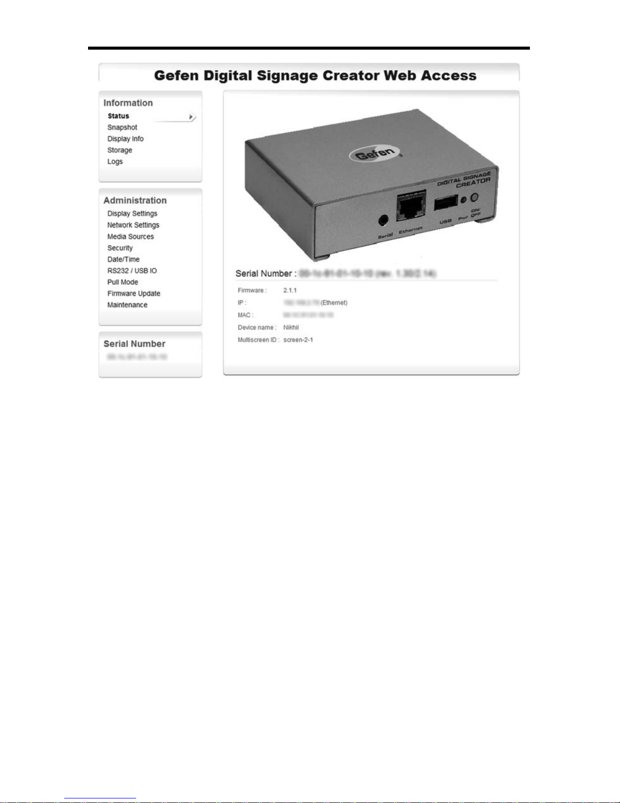
6. The browser should connect to the EXT-DSC HTTP server and display the
following page:
Page 12
9
ACCESSING THE EXT-DSC HTTP SERVER (PC)
7. Congratulations. You can now explore the HTTP server of your EXTDSC unit. Through this web interface you can administrate the unit and in
particular confi gure its network properties and video resolutions.
Troubleshooting
If you have not been able to connect to your EXT-DSC unit, please read the
following suggestions before contacting the Gefen support team.
1. Double check that you have correctly written the right address on your web
browser.
2. Check the LED on you EXT-DSC unit.
c. If the led is blinking fast (several times per second) from green to red.
Your EXT-DSC is in recovery mode. In this case, unplug and power
up again the EXT-DSC unit. Wait about 1 minute. If the EXT-DSC unit
remains in recovery mode contact support.
4. It may happen that your EXT-DSC unit has already been confi gured and
does not have the default setting to use DHCP. In this case you should reinitialize the unit to its factory default. Note that all the content stored on the
EXT-DSC unit will be deleted. Follow the instructions reported in Reset to
Factory default.
5. Double check the connectivity in your setup (cables, connectors, switches...).
Page 13

10
COMMUNICATING WITH THE EXT-DSC (MAC OSX)
6. Check the network confi guration of your PC.
7. Verify that the web browser does not have a proxy confi gured.
8. If you have checked all the above and the EXT-DSC HTTP server still cannot
be accessed, contact the support at support@Gefen.com.
Communicating with the EXT-DSC (MAC OSX)
This tutorial explains how to connect to your EXT-DSC unit from Mac OS X
without Hyper Media Director.
First we explain how to locate the EXT-DSC unit on the network and then how to
access and upload connect to the EXT-DSC.
Requirements:
► One EXT-DSC unit.
► A Mac computer running Mac OS X version 10.2 or later.
Finding The EXT-DSC On The Network:
This section explains how to fi nd the network address of an EXT-DSC unit
connected to the same local area network (LAN) as the Mac computer, or directly
to the Mac computer. This is particularly useful when the EXT-DSC unit has been
confi gured to use DHCP or when the static IP address that was confi gured has
been lost.
1. Verify that the EXT-DSC is powered on and running: the green LED should
blink once per second.
2. Verify that the EXT-DSC has network connectivity: the red LED should be on
but dim (not bright).
3. Open the Terminal program, which you’ll fi nd in the Applications Utilities
folder. The Terminal program presents a text based terminal where
commands can be typed.
4. Type the command
ping -c 3 224.0.0.1
and press Return. You will see multiple responses from all computers and/or
devices on the network.
Page 14

11
COMMUNICATING WITH THE EXT-DSC (MAC OSX)
5. Immediately after observing the responses, type the command
arp -a
and press Return. This will print out a list of known network names, IP
addresses and Ethernet MAC address, in the fi rst, second and fourth
columns, respectively.
Page 15

12
CONNECTING TO THE EXT-DSC CONTENT SERVER SERVER
6. Look in the list for the Ethernet MAC address that matches the serial number
of the EXT-DSC (e.g., 0:1c:91:0:0:6e for serial number 001c9100006e). All
MAC addresses of the EXT-DSC start with 0:1c:91.
7. The network name of the EXT-DSC unit appears on the fi rst column of the
matching line, if none is registered “?” is shown.
8. The IP address of the EXT-DSC unit appears, between parentheses, on the
second column of the matching line.
9. You may now close the Terminal application if so desired.
10. Now you can use either the network name, if one is registered or the IP
address to address the unit on the network.
Connecting To The EXT-DSC Content Server
This section explains how to connect to the EXT-DSC content using the Mac OS
X Finder.
1. Click anywhere on your desktop to bring up the Finder menu bar at the top
of the screen.
2. From the Go menu, select Connect to Server... The Connect to Server dialog
appears.
3. In the Server Address textbox type:
http:// followed by the IP address or network name of the EXT-DSC unit and
:81/.
For instance http://192.168.1.10:81/ to connect to the unit with the
192.168.1.10 IP address.
Page 16

13
AUTOMATIC DHCP CONFIGURATION
4. Click the Connect button. This will open the content folder on the EXT-DSC
unit in a Finder window.
5. The EXT-DSC unit is also added, using the typed network name or IP
address, to the list of connected network servers and one need not reconnect to it using this procedure.
Accessing / Copying Content From / To The EXT-DSC Unit:
This section explains how to access content from or copy (upload) content on the
EXT-DSC unit.
1. Open a Finder window.
2. Select the EXT-DSC unit on the list of connected servers on the left of the
window, it appears by the network name or IP address that was typed when
the connection was done.
3. On the right pane you now see all the content fi les on the EXT-DSC unit, you
can manage them as regular fi les on Mac OS X.
4. To copy fi les to the EXT-DSC unit (i.e. upload) just drag and drop fi les from
another Finder window to the right pane.
5. After uploading fi les allow some time for the EXT-DSC unit to notice the new
fi les.
Automatic DHCP Confi guration
This tutorial explains how to manually confi gure an EXT-DSC unit to connect to a
specifi c network using DHCP for the distribution of network addresses. Note that
this procedure assumes that you can access the HTTP server of the EXT-DSC
unit through the Ethernet interface.
1. Access the HTTP server of your EXT-DSC unit.
► If you have just received an EXT-DSC unit see the previous sections to
Page 17

14
AUTOMATIC DHCP CONFIGURATION
learn how to connect to its HTTP server.
► If the network confi guration of your EXT-DSC unit has already been
modifi ed follow the suggestions in Access HTTP server.
2. Select the Network confi guration page on the left menu under Basic.
► Under Current settings you can read the current network confi guration
of the EXT-DSC unit. In particular you can read the current IP address,
the Host name and the MAC address.
► Under Change settings you can confi gure the network settings of the
EXT-DSC unit.
3. Confi gure the EXT-DSC to use DHCP.
► Set the DHCP radio button instead of Static one.
4. Validate the changes.
► Validate the new network confi guration with the Update button.
► The changes will be valid once the EXT-DSC unit has rebooted. If you
want to immediately reboot the unit, check the Reboot now check box
before pressing the Update button.
5. Re-connect to your EXT-DSC.
► If your DHCP server is confi gured to register new computer to the
DNS you can access your EXT-DSC using the following address Error!
Hyperlink reference not valid..
► Otherwise you need to fi nd the IP address assigned to your EXT-DSC.
This can be done using the “discover device” feature of the DSD for
instance.
Page 18

15
AUTOMATIC DHCP CONFIGURATION
Troubleshooting
Once the device has rebooted, you can check the new confi guration by
accessing the HTTP server. Note that you need to use the new IP address of
the device name this time. If you are not able to connect to your EXT-DSC unit
after modifying the IP confi guration, please read the following suggestions before
contacting the Gefen support team.
1. Check the LED on your EXT-DSC unit.
► If the led is blinking once per second in orange color and the red led
is bright on then your EXT-DSC unit has been confi gured to activate
DHCP but no DHCP server has been detected on your network. Make
sure your DHCP server is working correctly.
► If the green led is blinking fast (several times per second) then your
EXT-DSC unit is in recovery mode. In this case, unplug and power up
again the EXT-DSC unit. Wait about 1 minute to complete the booting
procedure and check the led again. If the EXT-DSC unit remains in
recovery mode then contact Gefen Technical Support.
2. You don’t have a DHCP server
Page 19

16
FIXED IP CONFIGURATION
► In the case where your EXT-DSC unit has been confi gured to use
DHCP but the DHCP server cannot be contacted by the unit, you need
to reinitialize the unit to its factory default (See Reset to Factory default)
and restart the confi guration procedure.
Fixed IP Confi guration
This tutorial explains how to manually confi gure an EXT-DSC unit to connect
to a specifi c network with a fi xed IP address. Note that this procedure assumes
that you can access the HTTP server of the EXT-DSC unit through the Ethernet
interface.
1. Collect information on your network confi guration.
The following information should be available about your network:
► A range of free IP addresses that can be allocated to the EXT-DSC
unit(s) without network confl icts.
► The right subnet mask.
2. Access the HTTP server of your EXT-DSC unit.
► If you have just received an EXT-DSC unit see the previous sections to
learn how to connect to its HTTP server.
► If the network confi guration of your EXT-DSC unit has already been
modifi ed follow the suggestions in Access HTTP server.
3. Select the Network confi guration page on the left menu under Basic.
► Under Current settings you can read the current network confi guration
of the EXT-DSC unit. In particular you can read the current IP address,
the Host name and the MAC address.
► Under Change settings you can confi gure the network settings of the
EXT-DSC unit.
4. Set the static IP address and the subnet mask.
► Set the Static radio button instead of DHCP one.
► Attribute to the EXT-DSC unit a static IP address in the range of the free
IP addresses of your network.
► Also, make sure that the subnet mask corresponds to your network
confi guration.
► You may fi ll the other network parameters as well if known.
5. Validate the changes.
Page 20

17
USING THE EXT-DSC HTTP SERVER
► Validate the new network confi guration with the Update button.
► The changes will be valid once the EXT-DSC unit has rebooted. If you
want to immediately reboot the unit, check the Reboot now check box
before pressing the Update button.
Troubleshooting
Once the device has rebooted, you can check the new confi guration by
accessing the HTTP server. Note that you need to use the new IP address this
time. If you are not able to connect to your EXT-DSC unit after modifying the IP
confi guration, please read the following suggestions before contacting the Gefen
support team.
1. Check the LED on you EXT-DSC unit.
► If the led is blinking once per second in orange color and the red led is
bright on then you are in one of the following cases
• The IP address of your EXT-DSC unit has already been assigned
on the network. Check your network confi guration and make sure
that the address <new IP> is not taken by another device.
• Your EXT-DSC unit has been confi gured to activate DHCP but
no DHCP server has been detected on your network. Make sure
you have selected the Static radio button. If not, reboot the unit by
keeping pressed the push-button for few seconds.
► If the green led is blinking fast (several times per second) then your
EXT-DSC unit is in recovery mode. In this case, unplug and power up
again the EXT-DSC unit. Wait about 1 minute to complete the booting
procedure and check the led again. If the EXT-DSC unit remains in
recovery mode then contact support.
2. Wrong IP address
► In the case where your EXT-DSC unit has been confi gured with a wrong
IP address and cannot longer be contacted, you need to reinitialize the
unit to its factory default (See Reset to Factory default) and restart the
confi guration procedure.
Using The EXT-DSC HTTP Server
If you want access to the HTTP server for the fi rst time, please read the previous
connection sections fi rst. Otherwise make sure that you have a PC connected
to the EXT-DSC unit through Ethernet connection and that you have correctly
confi gured the PC and/or the EXT-DSC unit to be on the same network with the
right IP address.
Execute on the PC a Web browser such as Internet Explorer or Firefox. There
Page 21

18
USING THE EXT-DSC HTTP SERVER
are few ways to access the HTTP server of a specifi c EXT-DSC unit.
1. You know the IP address of the EXT-DSC unit: then type http://<ip address>
in the location bar of your web browser.
2. You know under which name the EXT-DSC unit has been registered on
the DNS server. This registration can be done manually by the DNS server
administrator and in this case the name of the unit is arbitrary. In this case
write http://<DNS name of the unit>/ in the location bar of your web browser.
3. You know that the EXT-DSC unit is confi gured in DHCP mode and that the
DHCP server is confi gured to dynamically register the names in the DNS
server. In this case the name of the EXT-DSC unit will have the following
predefi ned pattern: gef-dsc-<MAC Address>, where <serial number> is the
12 digit serial number that you fi nd on the label below the EXT-DSC unit. In
this case write http://gef-dsc-<MAC Address>.local in the location bar of
your web browser.
NOTE: If you do not know any of the above information, then you may retrieve
the IP address and the name of the EXT-DSC unit using the Digital Signage
Director software. This software shall be executed on the PC which is connected
through the Ethernet network to the EXT-DSC unit.
To validate that you have successfully connected to the HTTP server, you should
see the following screen:
Page 22

19
CONFIGURING DISPLAY SETTINGS
Confi guring Display Settings
This tutorial explains how to confi gure the display settings of your EXT-DSC unit
using its administration HTTP server.
1. In the main page of the HTTP server of your unit, select in the left menu the
Display Settings item that you fi nd under Administration. The current display
settings will be shown on your browser.
2. Choose the output resolution to activate. The Basic menu lets you select
between seven presets resolutions. For fi ner settings, you need to use the
Advanced menu.
The aspect ratio of your display will be automatically updated according to
the chosen resolution. You can modify it by checking the Force aspect ratio
check box.
3. Choose your display orientation. In case you are using a vertical display
make sure you select the correct rotation direction.
4. If you require audio output, you must enable it using the Enable Audio
Output check box.
The preview icon on the right helps you to choose the correct settings for your
display.
All changes need to be confi rmed with the Apply button, which will trigger a
reboot of the unit. The reboot process requires about 2 minutes to complete.
Page 23

20
USING A USB DRIVE WITH THE EXT-DSC
Using a USB Drive With the EXT-DSC
This tutorial explains how to confi gure USB drive as storage source by your EXT-
DSC unit using its administration HTTP server.
1. In the main page of the HTTP server of your unit, select in the left menu the
Media Sources item that you fi nd under Administration. The current settings
will be shown on your browser.
2. Make sure that the Primary source is set to “Local Storage”. The page
indicates that the local storage is currently set to the EXT-DSC internal
storage.
3. Check the “Set Local Storage to USB storage device when available” check
box
4. Press Apply.
5. Insert your USB storage into the USB connector of the EXT-DSC. Wait for
a few seconds and then press the Reload button. The page should indicate
Page 24

21
that the local storage is currently set to USB storage.
By default USB storage device are formatted using FAT fi le systems. This has the
advantage that the USB storage is readable both by the EXT-DSC and any PC.
However such USB device can only be used fro reading mode by the EXT-DSC.
If you need to use the USB storage permanently, you might want the EXT-DSC to
be able to write on the USB device. To do so, the USB must be formatted by the
EXT-DSC.
1. Plug your USB storage device to the EXT-DSC
2. Press the Format Now button
WARNING: all contents of the USB storage device will be erased.
NOTE: the USB storage device will no longer be recognized by Windows
PCs.
3. When the formatting is over, unplug the USB storage device from the EXTDSC
4. Plug the USB storage device to the EXT-DSC.
NOTE: you need now to upload content to the USB storage device using the
EXT-DSC WebDAV server.
If you are using a USB storage device in write mode, it is recommended to press
the Disconnect button before removing the device from the EXT-DSC.
USING A USB DRIVE WITH THE EXT-DSC
Page 25

22
CONTROLLING USER RIGHTS
Controlling User Rights
This tutorial explains how to access rights for your EXT-DSC unit using its
administration HTTP server.
The EXT-DSC offers three levels of security:
► Administrative Server: Controls the access to all pages of the HTTP
administration server. It is recommended to always protect this area.
► Content Server: Controls the access to all content displayed by the EXT-
DSC. This username and password will be needed to upload content on
the EXT-DSC.
► Monitoring: Controls the access to the logs and snapshot of the EXT-
DSC.
Confi guration Guide:
1. In the main page of the HTTP server of your unit, select in the left menu the
Security item that you fi nd under Administration. The current security settings
will be shown on your browser.
2. Chose the type of access you would like to confi gure.
NOTE: It is recommended to always setup a password for the Administrative
area. By default no password is set and the administrative area is not
protected.
3. Enter the password and confi rm it in the second text area.
4. Press Apply to save your changes.
NOTE: You need to press apply for each password you want to change.
Thus it is possible to change only one password at the time.
Page 26

23
CONFIGURING NETWORK CREDENTIALS FOR REMOTE SERVERS
If you want to confi gure password for remote server, please go to the Network
Credentials page.
Confi guring Network Credentials For Remote Servers
This tutorial explains how to confi gure network credentials for remote server
accessed by your EXT-DSC unit.
1. In the main page of the HTTP server of your unit, select in the left menu
the Media Sources item that you fi nd under Administration. Then click
on the Advanced tab on top of the window. The current settings will be
shown on your browser.
2. For each remote server protected by a password, enter:
► The server URI. The URI can also include a path on the server if
different users are needed for different part of the server.
Page 27

24
USING A NETWORK SERVER WITH THE EXT-DSC
► The username
► The password
► You can specify multiple username and password for the same
server but for different realms
3. If you need additional servers, press the Add server row button.
4. Press Apply to save your changes.
Note that networks credentials are used by the EXT-DSC player and by the pull
mechanism as described in Pull Mode settings.
Using A Network Server With EXT-DSC
This tutorial explains how to confi gure your EXT-DSC unit to use a network
server as content source using its administration HTTP server.
The EXT-DSC can use an HTTP server as the source for the displayed
multimedia fi les. In this case the EXT-DSC will frequently check for modifi cation
on the server. The internal storage will be used to cache some of media fi les from
the server. If you require your EXT-DSC to download periodically the content of a
network server to its internal storage, please go to the Content Pull Mode page.
1. In the main page of the HTTP server of your unit, select in the left menu
the Media Sources item that you fi nd under Administration. The current
settings will be shown on your browser.
2. Change the Primary source to be equal to Network Project
3. Enter the URI of your network project
The EXT-DSC will open the index.svg fi le in the root of the entered URI
Note: you can use HTTP or HTTPS servers
Page 28

25
CONTENT ACCESS MODES
4. Press Apply
You can specify a Fallback source in case your network server cannot be
reached by the EXT-DSC unit.
If your server requires a username and a password, you can enter them using
the Advanced dialog page as described in Network credentials.
Content Access Modes
When connected to the network, EXT-DSC can be used to access content to be
displayed in three different modes:
► Push mode: Files are pushed to the EXT-DSC using a WebDAV server.
For example, the DSD uses the push mode to publish an Hyper Media
Project to a EXT-DSC unit.
► Client mode: The EXT-DSC accesses fi les from a remote HTTP server.
The internal storage will be used as a cache. Confi guring the client
mode is explained in Use network servers.
► Pull mode: Files are copied periodically from a remote server to the
local storage of the EXT-DSC.
If the Push and Client modes are the simpler publishing mechanisms they might
not fi t to all network architecture needs. In particular, when network security
constraints are introduced, it may be necessary to request the EXT-DSC units
to retrieve content or publish logs at specifi c timings. In this case the Pull mode
must be used.
Page 29

26
PULL MODE
To be activated, the Pull mode requires specifi c actions. In this section and its
subsections we document specifi cally this mode.
The Pull mode of Content Access
The Pull mode is confi gured through the HTTP confi guration interface, under
Administration/Pull mode.
The Pull mode can be used bidirectional to:
► Automatically publish fi les to the EXT-DSC.
Each time the EXT-DSC has been scheduled to update the content of its
local storage, it will connect to the specifi ed server, check for changes, and
download all modifi ed fi les.
► Upload logs and previews to a remote WebDAV server.
The publish action of the Pull mode can be used with WebDAV server or with
standard HTTP servers. In this last case an XML fi les describing the content of
the server must be available. The Pull mode timings can be confi gured either
directly from the HTTP interface or using iCalendar fi les.
There are two ways to confi gure the Pull mode on a EXT-DSC unit:
Page 30

27
HOW TO CONFIGURE THE EXT -DSC TO USE THE SERIAL PORT
► Using the simple HTTP interface. This option is easy to confi gure, but has
some limitations. For example, it forces a daily project publishing at a specifi c timing. Moreover, the options for uploading logs are limited.
► Using iCalendar schedule fi les: This option gives you full control over the
Pull mode of the EXT-DSC, but requires an external tool to create the iCalendar fi les (Mozilla Sunbird for instance).
How to Confi gure the EXT-DSC to Use the Serial Port
The Gefen EXT-DSC can control external appliances using its serial port (RS-
232) interface. This type of interface is supported in particular by most profes-
sional monitors to allow switch on/off operations or image confi gurations.
To control an appliance trough the serial port interface you need the following:
► A protocol fi le for your appliance.
► Testing and debugging your protocol fi le can be done on a PC using the Se-
rial Port Protocol Studio application.
► The protocol fi le must be uploaded to the EXT-DSC and enabled.
► You need to build or purchase the serial port cable to connect your appliance
to the EXT-DSC.
► Special Gefen elements <auxCmd> need to be included into your content to
control the appliance.
For more information on controlling appliance with the serial port, you can check
the online documentation for the serial port or the RS-232 section of the FORUM.
Enabling RS-232
Enabling the RS-232 support is done using the HTTP administration interface
and the Serial Port menu as shown in the image below.
Page 31

28
CONFIGURING RS-232
By default the serial port control is disabled. It is enabled by selecting a protocol
fi le in the Protocols drop-box. Choose either pre-loaded fi les designed by Gefen
(identifi ed by the prefi x [sys] before the name of the protocol), or fi les that you
have uploaded using the Upload function.
Confi guring RS-232
The drop down menu below shows an EXT-DSC’s confi guration where the follow-
ing protocol fi les can be selected:
► No protocol fi les, the RS-232 interface is disabled ([disabled])
► A system version of the Sharp Aquos protocol ([sys]sharp_aquos)
► An uploaded protocol fi le for the LG LF65 screen (LG LF65)
► An uploaded protocol fi le for the Sharp Aquos monitors (sharp_aquos)
Page 32

29
CONFIGURING RS-232
Once a protocol fi le is selected, you might choose to change the serial port con-
fi guration or to enable automatic power on and power off of the attached screen.
Checking the Control monitor power check box will force the EXT-DSC to send
the PowerOn and PowerOff commands at specifi ed times (in 24 hours format)
regardless of the content uploaded on the device.
In the example below the EXT-DSC has been confi gured to use the LG LF65
protocol, and automatically turn the screen ON at 8:00 and OFF at 20:00.
Page 33

30
SPECIFICATIONS
Digital Display Compatibility
Aspect Ratio 16:9, 16:10, 4:3 (horizontal & vertical)
Maximum resolution 1280x720 (16:9), 1024x640 (16:10), 1024x768 (4:3)
Video output 720p (HD-Ready), 576p, 480p, VGA; 50 or 60 fps
Video connectors
HDMI (incl. digital audio), DVI via adapter. VGA (DB15
HD connector). Simultaneous use of HDMI and VGA
outputs is possible.
Media Format
Description language SVG Tiny 1.2+ (Scalable Vector Graphics)
Media synchronization SMIL 2.1 (Synchronized Multimedia Integration
Language)
Still image formats JPEG, PNG, GIF, SVG
Supported video codecs Up to SD resolution: MPEG-4 ASP, MPEG-
2, MPEG-1, H.264, MJPEG, Microsoft VC-1
(Windows Media Video 9)
Supported audio codecs MPEG audio layer 1/2/3 (MP3), ITU G.711, G.722,
G.729,PCM, Microsoft WMA, Real Audio
Media container formats AVI, WMV/WMA, VOB, AIFF, OGG, WAV
Streaming media protocol MMS, RTSP, RTP, SDP, HTTP; Uni- & multicast
Import fi lters provided for Flash 9, Microsoft PowerPoint presentations, BMP,
TIFF, XPM, WBMP, PNM bitmaps
Scripting language PHP5, JavaScript
Content scheduling iCalendar (RFC2445)
Graphic Effects Engine
Graphic effects language SVG Tiny 1.2+
Vector graphics primitives Rectangles, polygons, paths with lines, elliptical
arcs and Bezier curves, text areas, linear and
radial gradients
International text support Unicode standard compliant with bidirectional text
support
Font fi le formats TrueType and OpenType
Animation capabilities Color, gradients, transparency level, audio
volume, motion along a path, translation, scaling,
rotation, clipping
Animation modes Discrete, linear, paced and spline interpolation
Page 34

31
SPECIFICATIONS
Specialized Applications
Interactivity events Touch screen, keyboard and mouse via USB 2.0 port,
user defi ned serial port
Time synchronized Millisecond accuracy, for unconstrained video wall
confi gurations
Network
Connectivity Ethernet 10/100 Mbit/s (RJ-45), IEEE 802.3u, 802.3x
Protocols IPv4, DHCP or fi xed address
Remote confi guration HTTP confi guration server, password protected
Content administration WebDAV server, password protected
Other protocols SNMPv1/v2c, NTP
Content updates Pull mode, push mode, server based
Storage
Internal storage 2GB solid state
External storage Flash drives and hard disks via USB 2.0 port
Physical Specifi cation
Size 105(W) x 26(H) x 83(D) mm 4.13’(W) x 1.02’(H) x
3.27’(D)
Weight 190g / 6.7 oz
Power Consumption 5V DC, typ. 0.4A (2W)
Power supply input 100-240V 50-60 Hz, max input current 0.6A
Operating temperature 0ºC to 40ºC / 32ºF to 104ºF; 10% to 90% RH
Storage temperature -25ºC to 45ºC / -13ºF to 113ºF; 10% to 90% RH
Real time clock Min. accuracy 1 minute/month free running, battery
backed
Serial RS-232, up to 115200 baud, mini-jack 3.5mm
Analog audio output Line level, stereo, mini-jack 3.5mm
Page 35

32
Gefen warrants the equipment it manufactures to be free from defects in material
and workmanship.
If equipment fails because of such defects and Gefen is notifi ed within two (2)
years from the date of shipment, Gefen will, at its option, repair or replace the
equipment, provided that the equipment has not been subjected to mechanical,
electrical, or other abuse or modifi cations. Equipment that fails under conditions
other than those covered will be repaired at the current price of parts and labor in
effect at the time of repair. Such repairs are warranted for ninety (90) days from
the day of reshipment to the Buyer.
This warranty is in lieu of all other warranties expressed or implied, including
without limitation, any implied warranty or merchantability or fi tness for any
particular purpose, all of which are expressly disclaimed.
1. Proof of sale may be required in order to claim warranty.
2. Customers outside the US are responsible for shipping charges to and from
Gefen.
3. Copper cables are limited to a 30 day warranty and cables must be in their
original condition.
The information in this manual has been carefully checked and is believed to
be accurate. However, Gefen assumes no responsibility for any inaccuracies
that may be contained in this manual. In no event will Gefen be liable for
direct, indirect, special, incidental, or consequential damages resulting from
any defect or omission in this manual, even if advised of the possibility of such
damages. The technical information contained herein regarding the features and
specifi cations is subject to change without notice.
For the latest warranty coverage information, please visit Gefen’s Warranty web
page at http://www.gefen.com/kvm/aboutus/warranty.jsp
PRODUCT REGISTRATION
Please register your product online by visiting Gefen’s web site at
http://www.gefen.com/kvm/Registry/Registration.jsp
WARRANTY
Page 36

Page 37

Rev X2
20600 Nordhoff St., Chatsworth CA 91311
1-800-545-6900 818-772-9100 fax: 818-772-9120
www.gefen.com support@gefen.com
Pb
 Loading...