

Page 1
®
4x4 Component
Matrix over
CAT-5
EXT-COMPAUD-CAT5-444
User Manual
www.gefen.com
Page 2

ASKING FOR ASSISTANCE
Technical Support:
Telephone (818) 772-9100
(800) 545-6900
Fax (818) 772-9120
Technical Support Hours:
8:00 AM to 5:00 PM Monday thru Friday PST
Write To:
Gefen, LLC
c/o Customer Service
20600 Nordhoff St
Chatsworth, CA 91311
www.gefen.com
support@gefen.com
Notice
Gefen, LLC reserves the right to make changes in the hard ware, packaging and
any accompanying doc u men ta tion without prior written notice.
4x4 Component Matrix Over CAT-5 is a trademark of Gefen, LLC
© 2010 Gefen, LLC, All Rights Reserved
All trademarks are the property of their respective companies
Rev A4
Page 3

CONTENTS
1 Introduction
2 Operation Notes
3 Features
4 4x4 Component Matrix Over CAT-5 Front Panel Layout
5 4x4 Component Matrix Over CAT-5 Front Panel Descriptions
6 4x4 Component Matrix Over CAT-5 Back Panel Layout
7 4x4 Component Matrix Over CAT-5 Back Panel Descriptions
8 4X4 Component Audio Over CAT-5 Receiver Panel Layout
9 4X4 Component Audio Over CAT-5 Receiver Panel Description
10 Connecting And Operating The 4x4 Component Matrix Over CAT-5
11 Operating The 4x4 Component Matrix Over CAT-5 Receiver
12 RMT-16IR Remote Description
13 Adjusting The 4x4 Component Matrix Over CAT-5 Receiver
14 RMT-16IR Remote Control Installation
15 RMT-16IR Remote Control Confi guration
16 RMT-4IR Remote Control Installation
17 RMT-4IR Remote Control Confi guration
18 RS-232 Serial Control Interface
19 Network Cable Wiring Diagram
20 Rack Mount Installation
21 Specifi cations
22 Warranty
Page 4

INTRODUCTION
Congratulations on your purchase of the 4x4 Component Matrix Over CAT-5.
Your complete satisfaction is very important to us.
Gefen
Gefen delivers innovative, progressive computer and electronics add-on solutions
that harness integration, extension, distribution and conversion technologies.
Gefen’s reliable, plug-and-play products supplement cross-platform computer
systems, professional audio/video environments and HDTV systems of all sizes
with hard-working solutions that are easy to implement and simple to operate.
The Gefen 4x4 Component Matrix Over CAT-5
The Gefen 4x4 Component/Audio CAT5 Matrix offers unprecedented fl exibility
and convenience by routing high defi nition video and analog/digital audio
from any of four Component video sources to any of 4 remote displays over
inexpensive, standard CAT-5 cabling.
Each remote display has a control box that allows the viewer to select any of the
4 video sources and control that source via an IR remote control as if the viewer
was standing in the room where the source originates.
Full High-Resolution HDTV signals are supported up to a resolution of 1080p at a
maximum distance of 1000 feet. The Gefen 4x4 Component/Audio CAT5 Matrix
works with any Component video source including DVD players, cable boxes,
and satellite set-top boxes that connect to a Component display. Every source is
accessible at all times by any display by selecting it with the IR remote.
How It Works
You simply connect up to 4 local Component video and analog/digital audio
sources to the Matrix’s inputs. Connect the included 1-foot loop back cables into
the upper board for the CAT-5 extension function. Then run each of your CAT-5
cables from the Matrix to the remote displays. At each remote display, terminate
the CAT-5 cable run with a Component/Audio CAT5 Receiver device. Connect
each Receiver to a display and your analog/digital audio equipment and you’re all
set.
1
Page 5

OPERATION NOTES
READ THESE NOTES BEFORE INSTALLING OR
OPERATING THE 4X4 COMPONENT MATRIX OVER CAT-5
• The extender functionality of the 4x4 Component Matrix Over CAT-5 requires
the use of the supplied 1 foot component video and audio jumper cables.
These cables must be used to connect the component video and audio
output ports to the component video and audio extension input ports.
• IR repeater functionality is only from the receiving unit to the sending unit. IR
data cannot be transmitted from the sending unit to the receiving unit.
• A single CAT cable is needed for each extension. Gefen recommends using
solid core CAT-5e cabling. Termination should adhere to the TIA/EIA-568-B
specifi cation. See page 19 for details.
• The 4x4 Component Matrix over CAT-5 Receiver unit has a Focus EQ
trimpot to compensate for color convergence (color bleeding) or when no
picture is displayed; both of which are caused by variances that can be
found in different CAT-5 cable brands. See page 13 for details.
2
Page 6

FEATURES
Features
• Switches easily between any four component/audio sources
• Sends up to four video inputs to any four remote displays
• Maintains 1920 x 1200, Full 1080p HD, and 2k resolution video
• Extends video up to 1000 feet (300 meters) over CAT-5 cable
• IR remote
• RS-232 serial port
• Rack ears
Package Includes
(1) 4x4 Component/Audio CAT5 Matrix
(4) Component/Audio over CAT5 Receiver Units
(4) RMT-4 Infrared Remote Controls
(4) 1 Foot 5 RCA Component Video/Audio Cables
(4) 6 Foot 5 RCA Component Video/Audio cables
(4) 5V DC Power Supplies (for Receivers)
(1) 24V DC Power Supply (for Matrix)
(1) Rack Ears
(1) User Manual
3
Page 7
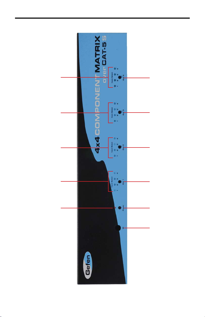
4X4 COMPONENT MATRIX OVER CAT-5 FRONT
PANEL LAYOUT
12 3 4 5
67 8 9 10 11
4
Page 8

4X4 COMPONENT MATRIX OVER CAT-5 FRONT
PANEL DESCRIPTIONS
1 Power LED Indicator
This LED will become active once the included 24V DC power adapter is
properly connected.
2 Output 1 Source LED Indicator
The currently selected source being displayed on Monitor Output 1 will be
visually acknowledged by an active LED. There are 4 LED’s, one for each input
source.
3 Output 2 Source LED Indicator
The currently selected source being displayed on Monitor Output 2 will be
visually acknowledged by an active LED. There are 4 LED’s, one for each input
source.
4 Output 3 Source LED Indicator
The currently selected source being displayed on Monitor Output 3 will be
visually acknowledged by an active LED. There are 4 LED’s, one for each input
source.
5 Output 4 Source LED Indicator
The currently selected source being displayed on Monitor Output 4 will be
visually acknowledged by an active LED. There are 4 LED’s, one for each input
source.
6 IR Receiver
This port will receive IR commands from the included RMT-16IR remote control.
7 Power Button
Pressing this button while the unit is on will place the unit in stand-by mode.
Pressing this button again while the unit is in stand-by will turn it on.
8 Output 1 Source Button
Each press of this button will cycle through the 4 inputs which will be displayed
on the Monitor Output 1.
9 Output 2 Source Button
Each press of this button will cycle through the 4 inputs which will be displayed
on the Monitor Output 2.
10 Output 3 Source Button
Each press of this button will cycle through the 4 inputs which will be displayed
on the Monitor Output 3.
1 1 Output 4 Source Button
Each press of this button will cycle through the 4 inputs which will be displayed
on the Monitor Output 4.
5
Page 9

4X4 COMPONENT MATRIX OVER CAT-5 BACK
PANEL LAYOUT
1 2 3
4 5 6 7
6
Page 10

4X4 COMPONENT MATRIX OVER CAT-5 BACK
PANEL DESCRIPTIONS
1 Component With Audio Extension Input
Connect the included jumper cables between the Component With Audio
Outputs (Item 5 on this page) and these inputs. Inputs include component video,
analog audio, and digital audio connectors. There are 4 inputs that are used in
conjunction with the CA T-5 output ports for extension.
2 IR Blaster Outputs
Connect IR emitters/blaster (sold separately , Gefen Part # EXT-2IREMIT) to
these output ports. Each output is linked to one of the extension receivers. IR
information is relayed from each remote location and is sent to these blasters for
control of local equipment from the extended location. Place the blaster “eye” on
or near the IR receiver of the connected equipment.
3 CAT -5 Extension Ports
Connect user supplied CA T-5e cables between these ports and the 4x4
Component Audio Over CAT-5 Receivers at remote locations. These cables
will transmit the component and audio signals to the remote locations while
receiving IR data from each receiver.
4 RS-232 Serial Control Interface
This port is used for control of the 4x4 Component Audio Over CAT-5 by RS-232
serial communication. Please see page 18 for more information.
5 Component With Audio Outputs
Connect the included jumper cables between the Component With Audio
Extension inputs (Item 1 on this page) and these inputs. Outputs include
component video, analog audio, and digital audio connectors. There are 4
outputs.
6 Component With Audio Inputs
Connect the component video and audio source devices to these input ports
using the supplied component and audio cables. Up to 4 sources can be
connected at one time. Inputs include component video, analog audio, and
digital coaxial connectors.
7 24V DV Power Input
Connect the included 24V DC power supply to this input.
7
Page 11

4X4 COMPONENT AUDIO OVER CAT-5 RECEIVER
PANEL LAYOUT
Front Panel
1
5
2
Back Panel
Top Panel
3
74
8 9 106
11
8
Page 12

4X4 COMPONENT AUDIO OVER CAT-5 RECEIVER
PANEL DESCRIPTION
1 IR Receiver
This receiver will receive commands from both the included RMT-4IR remote
control and from other commercial IR remote controls. IR commands from
commercial IR remote controls are relayed from this unit back to the 4x4
Component Audio Over CAT-5 sending unit where they will be output by the
attached IR Blasters.
2 Selected Source LED
The currently selected source that is being displayed on the attached monitor
will be visually acknowledged by an active LED. There are 4 LEDs, one for each
source.
3 Brightness & Focus Adjustment Trim Pots
Brightness and focus Trim Pots are available for fi ne tuning the output video
signal. Please see page 12 for more information and instructions on usage.
4 5V DV Power Input
Connect the included 5V DV power adapter to this input. Once a proper
connection is made the power LED indicator should become active.
5 Component Video Output
Connect the component display to this output using user supplied cables.
6 CAT -5 Extension Port
Connect a user supplied CA T-5e cable between the CAT-5 extension ports on
the 4x4 Component Audio Over CAT-5 sending unit and this port.
7 Analog RCA Stereo Audio Output
Connect this output to either the display’s analog audio input or a receiver’s
analog audio input using user supplied analog audio cables.
8 Digital Coaxial Audio output
Connect this output to either the display’s digital coaxial audio input or a
receiver’s digital coaxial audio input using a user supplied digital coaxial audio
cable.
9 Digital Optical Audio output
Connect this output to either the display’s digital optical audio input or a
receiver’s digital optical audio input using a user supplied digital optical audio
cable.
10 IR Extension Port
Connect the optional IR Receiver Extension (part# EXT-RMT-EXTIR) to this
port.
1 1 Direct Select Buttons
Use buttons 1 through 4 to select what source the connected display will be
view.
9
Page 13

CONNECTING AND OPERATING THE 4X4 COMPONENT MATRIX OVER CAT-5
How to Connect the 4x4 Component Matrix Over CAT-5
1. Connect up to 4 component video/audio source devices to the 4x4
Component Matrix Over CAT-5 sending unit using the included 5 RCA
component video/audio cables.
2. Optionally, connect up to 4 digital coaxial audio source devices to the 4x4
Component Matrix Over CAT-5 sending unit using one of the RCA cables
from the supplied 5 RCA component/audio cable.
3. Using the included 5 RCA component video/audio jumper cables, connect
the Component Video/Audio Output ports to the Component Video/Audio
Extension Input ports. Please see the panel layout on page 6 for the
locations of these ports.
4. If using digital coaxial audio, connect the digital coaxial outputs to the LEFT
ANALOG connector of each of the Component Video/Audio Extension Input
ports. This port will automatically detect the digital audio and send it to the
appropriate digital output ports on the 4x4 Component Audio Over CAT-5
receiving units.
5. Connect the 4x4 Component Audio Over CAT-5 sending and receiving units
together using user supplied CAT-5e cables.
NOTE: If fi eld terminating CAT cabling please ensure that terminations adhere to
the TIA/EIA-568-B specifi cation. Please see page 19 more information.
6. Connect a component display to each of the 4x4 Component Matrix Over
CAT-5 receiving units using user supplied component cables.
7. Connect analog/digital audio to either the component display or a separate
audio receiver.
NOTE: The 4x4 Component Matrix Over CAT-5 receiver units will cross-convert
analog/digital stereo audio formats. If the source audio is 2 channel digital or
analog, both analog and digital outputs will be active on the receiver units. If
the source audio is digital multi-channel bit-stream, only audio from the digital
outputs will be active on the receiver units.
8. Connect the included 24V DC power supply to the 4x4 Component Matrix
Over CAT-5 sending unit. Connect each of the included 5V DC power
supplies to each of the 4x4 Component Matrix Over CAT-5 receiving units.
9. Power on the displays and source devices.
10
Page 14

OPERATING THE 4X4 COMPONENT MATRIX OVER CAT-5 RECEIVER
The 4x4 Component Matrix Over CA T-5 Receiver can be placed at each remote
location. Each receiver can switch between the four sources connected to the 4x4
Component Over CA T-5 Matrix sender. The unit has two methods of switching using
either the direct selection buttons or the RMT-4IR remote control.
Switching Using The Direct Selection Buttons
Each numbered button on the top panel of the 4x4 Component Matrix Over CA T-5
Receiver corresponds to component inputs 1 through 4 on the 4x4 Component
Matrix Over CA T-5 sending unit.
1. Press the button on the top panel of the receiver that corresponds to the input
that you wish to view.
Switching Using The Direct Selection Buttons
The RMT-4IR remote has 4 numbered buttons that correspond to inputs 1 through 4
on the 4x4 Component Matrix Over CA T-5 sender unit.
1. Press the button on the RMT-4IR remote control that corresponds to the input
that you wish to view.
Using the IR Repeater Feature
Each 4x4 Component Matrix Over CA T-5 receiver can receive commands from
standard consumer IR remote controls and send them back to the sender unit for
output through the IR emitters/blasters. This allows the user to control the equipment
connected to the sender from the remote location. The IR emitters (part# EXT2IREMIT) are sold separately .
1. Connect an IR blaster to the IR Blaster output port on the rear panel of the 4x4
Component Matrix Over CA T-5 sender unit. Each of the 4 numbered output
ports correspond to each of the 4 CA T-5 extension ports. Connect the IR emitter
to the same port number of the remote receiver that you wish to use.
2. Remove the adhesive from the IR blaster’s emitter eye and place it on or near
IR receiver of the connected equipment.
3. Using the IR remote control of the equipment that has the IR emitter attached to
it, send commands to the 4x4 Component Matrix CA T-5 receiver at the remote
location. These IR command will be routed back to the sender and output
through the IR blasters to control the attached source device.
11
Page 15

OPTIONAL RMT-16IR REMOTE DESCRIPTION
LE
LED Indicator
Input
Selection
Buttons
The optional RMT-16IR remote control will allow the user to select which source
each of the 4 connected displays will be viewing at the source location. Each of the
4 displays are assigned a group of 4 buttons that correspond to the 4 source inputs.
Please use the information below when selecting the desired source for each display .
RMT-16IR Button Display Source
111
212
313
414
521
622
723
824
931
10 3 2
11 3 3
12 3 4
13 4 1
14 4 2
15 4 3
16 4 4
12
Page 16

ADJUSTING THE 4X4 COMPONENT MATRIX OVER CAT-5 RECEIVER
Each 4x4 Component Matrix Over CAT-5 Receiver has two trim pots used to
adjust the brightness and focus of the video output. These adjustment trim pots
are located on the front panel of each unit. Please use the guidelines below for
adjusting both trim pots. (The trim pots are labelled #3 in the call-out diagram on
page 8. They are located on the front panel of the unit).
4x4 Component Matrix Over CAT-5
Receiver - Front Panel
Trim Pots
Brightness
If the image appears too dim or too bright, adjust the brightness trim pot.
1. Insert a small fl athead adjustment tool into the trim pot.
2. Turn the trim pot in a clockwise fashion until the trim pot stops turning. Do
not force the trim pot beyond this point as it may break and will render the
trim pot useless.
3. Turn the trim pot in millimeter increments in a counter-clockwise fashion until
the desired brightness is reached.
4. Remove the trim pot adjustment tool.
Focus
The 4x4 Component Matrix over CAT-5 Receiver unit has a Focus EQ trimpot
to compensate for color convergence (color bleeding) or when no picture is
displayed; both of which are caused by variances that can be found in different
CAT-5 cable brands. NOTE: The focus trimpot is not only used for focusing the
picture, but is the difference between a picture and no picture if the trimpot is out
of range.
1. Insert a small fl at-head screwdriver into the trimpot on the front panel of the
Receiver unit.
2. Start by turning the EQ trimpot until a picture appears or the signal shows
best results.
3. Remove the small fl at-head screwdriver from the trimpot.
13
Page 17

OPTIONAL REMOTE CONTROL INSTALLATION
1. Remove battery cover from the back of the RMT-16IR remote.
2. Verify that DIP switches 1 & 2 are in the down (OFF) position.
3. Insert the battery, hold the battery so that you can see the positive side facing
up. The side that is not marked must be facing down.
4. Test the RMT-16-IR remote by pressing ONLY one button at a time. The
indicator light on the remote will fl ash once each time you press a button.
WARNING: Do not press multiple buttons simultaneously and do NOT press buttons
rapidly . These actions will cause the remote to reset and steps 1-4 will have to be
repeated.
NOTE: The RMT-16-IR ships with two batteries. One battery is required for
operation, the second battery is a spare.
Empty
Battery
Slot
DIP
Switches
Above: Picture of the opened rear battery compartment of the optional
RMT-16IR remote showing the exposed DIP Switch bank between the
battery chambers.
es
14
Page 18

OPTIONAL RMT-16IR REMOTE CONTROL CONFIGURATION
How to Resolve IR Code Confl icts on the Sender
In the event that IR commands from other remote controls confl ict with the
optional RMT-16IR remote control, changing the remote channel will alleviate this
issue. The RMT-16IR remote control, which is sold separately, has a bank of DIP
(Dual Inline Package) switches for confi guring the remote channel that both units
use to communicate. The 4x4 Component w/Audio Matrix can be put into a mode
that will uses its front LED array to indicate which remote channel is being used
and also give the user the ability to modify the currently used IR remote channel.
These IR channel settings must exactly match each other for proper operation.
The DIP Switch bank on the optional RMT-16IR is located underneath the battery
cover as shown on page 14. Below are the possible settings of the DIP switches
for selecting IR channels 1-4:
Channel 1:
Default
1 2
Channel 3:
1 2
Channel 2:
1 2
Channel 4:
1 2
Follow these steps to place the 4x4 Component w/Audio Matrix into IR channel
setup mode.
1. Turn on the 4x4 Component w/Audio Matrix.
2. Press and hold the front panel POWER button for 5 seconds to enter the
setup mode (All output LED’s except for Output 1 will be off). The Output 1
LED source indicator (page 4) will display the currently selected IR channel.
The active LED, either 1, 2, 3, or 4, will indicate which IR channel is being
used.
3. Note the IR channel used on the RMT-16IR remote and press the Output 1
selector button to cycle to the IR channel that is being used.
4. Press the POWER button to save the settings and exit the IR channel setup
mode.
Output-1
Output-1
Output-1
Output-1
1
234
Channel 1
1
234
Channel 2
15
1
234
Channel 3
1
234
Channel 4
Page 19

RMT-4IR REMOTE CONTROL INSTALLATION
LED Indicator
Input Selection
Buttons
Each extended location with a 4x4 Component Matrix Over CA T-5 Receiver can use
an RMT-4IR remote control to choose which source will be viewed by the attached
display . Pressing the numbered buttons will switch to the source connected to the
same numbered input on the 4x4 Component Matrix Over CA T-5.
To use the RMT-4IR remote, remove the battery cover on the back of the remote
to reveal the battery compartment (see page 14 for a picture). Insert the included
battery into the open battery slot. The positive (+) should be facing up. Ensure that
the both dip switches are in the OFF position. Replace the battery cover.
The remote ships with 2 batteries. One battery is required for operation and the other
battery is a spare.
16
Page 20

RMT-4IR REMOTE CONTROL CONFIGURATION
How to Resolve IR Code Confl icts on the Receiver
In the event that IR commands from other remote controls confl ict with the
supplied RMT-4IR remote control, changing the remote channel will alleviate this
issue. The RMT-4IR remote control and the 4x4 Component Matrix Over CAT-5
receiver have DIP SWITCHES for confi guring the remote channel that both units
use to communicate. These settings must match each other for proper operation.
The 2 DIP SWITCH bank on the RMT-4IR is located underneath the battery
cover (please see page 14 for a picture). The 4 DIP SWITCH bank for the 4x4
Component Matrix Over CAT-5 receiver is located on the underside of the unit
beneath a black piece of metallic tape. DIP SWITCH 1 and 2 on the RMT-4IR
correspond to *DIP SWITCH 1 and 2 on the 4x4 Component Matrix Over CAT-5
receiver.
NOTE: *DIP SWITCHES 3 and 4 are not used on the 4x4 Component Matrix
Over CAT-5 receiver.
IR Remote
Remote Channel 1:
Default
Remote Channel 3:
Remote Channel 1:
Default
Remote Channel 3:
1
2
123
Remote Channel 2:
1 2
Remote Channel 4:
1 2
1 2
1 2
4x4 Component Matrix
Over CAT-5 receiver
Remote Channel 2:
3
4
Remote Channel 4:
4
123
1
2
4
3
4
17
Page 21

RS-232 SERIAL CONTROL INTERFACE
54321
9876
Only Pins 2 (RX), 3 (TX), and 5 (Ground) are used on the RS-232 serial interface
Binary Table
ASCII Corresponding
RMT16-IR
Button
1 1 0011 0001 9 9 0011 1001
2 2 0011 0010 a 10 0110 0001
3 3 0011 0011 b 11 0110 0010
4 4 0011 0100 c 12 0110 0011
5 5 0011 0101 d 13 0110 0100
6 6 0011 0110 e 14 0110 0101
7 7 0011 0111 f 15 0110 0110
8 8 0011 1000 g 16 0110 0111
RS232 Settings
Binary ASCII Corresponding
RMT16-IR
12345
6789
Button
Binary
Bits per second ................................................................................................. 19200
Data bits .................................................................................................................... 8
Parity .................................................................................................................. None
Stop bits .....................................................................................................................1
Flow Control ....................................................................................................... None
18
Page 22

NETWORK CABLE WIRING DIAGRAM
Gefen recommends the TIA/EIA-568-B wiring option. Please adhere to the table
below when fi eld-terminating the CAT-5 cable for use with Gefen products. .
Pin Color
1 Orange / White
2 Orange
3 Green / White
4 Blue
5 Blue / White
6 Green
7 Brown / White
8 Brown
CAT-5, CAT-5e, and CAT-6 cabling comes in stranded and solid core types.
Gefen recommends using solid core cabling.
It is recommended to use one continuous run from one end to the other.
Connecting through a patch is not recommended.
12345678
19
Page 23

RACK MOUNT INSTALLATION
Rack mount ears are provided for installation of this unit into a 1U rack mount
space.
1. Locate the side screws on the unit.
2. Remove the front 2 screws that are located closest to the front of the unit.
3. Using the removed screws, screw the rack mounting bracket into the unit.
4. Repeat the procedure on the opposite side of the unit.
1
2
3
Front of unit
Rear of unit
4
20
Page 24

SPECIFICATIONS
Video Amplifi er Bandwidth ....................................................................... 350 MHz
Input Video Signal .............................................................................. 1.2 volts p-p
Video Resolutions ........................................................................................ 1080p
Video Connector ...................................................................... RCA-style RGB x 3
Analog Audio Connector ................................................. RCA-style L + R (Stereo)
Digital Audio Connector ...... S/PDIF Coax. (Matrix), S/PDIF & TOSlink (Receiver)
Link Connector .............................................................................. RJ-45 Shielded
Remote Control Port .................................................... RS232 female, mini-stereo
Power Supply Sender .................... 24V DC (60 Watts) Receiver 5V DC (5 Watts)
Dimensions Sender .......................................................... 17”W x 3.5”H x 5.875”D
Dimensions Receiver .......................................................... 6.6”W x 1.3”H x 2.7”D
Shipping Weight ........................................................................................... 16 lbs
21
Page 25

WARRANTY
Gef
f
y
e
e
eff
p
Gef
3
s
pag
p
N
en warrants the equipment it manufactures to be free from defects in material
and workmanship.
I
equipment fails because of such defects and Gefen is notifi ed within two (2)
ears from the date of shipment, Gefen will, at its option, repair or replace the
quipment, provided that the equipment has not been subjected to mechanical,
lectrical, or other abuse or modifi cations. Equipment that fails under conditions
other than those covered will be repaired at the current price of parts and labor in
ect at the time of repair. Such repairs are warranted for ninety (90) days from
the day of reshipment to the Buyer.
This warranty is in lieu of all other warranties expressed or implied, including
without limitation, any implied warranty or merchantability or fi tness for any
articular purpose, all of which are expressly disclaimed.
1. Proof of sale may be required in order to claim warranty.
2.Customers outside the US are responsible for shipping charges to and from
en.
.Copper cables are limited to a 30 day warranty and cables must be in their
original condition.
The information in this manual has been carefully checked and is believed to
be accurate. However, Gefen assumes no responsibility for any inaccuracies
that may be contained in this manual. In no event will Gefen be liable for
direct, indirect, special, incidental, or consequential damages resulting from
any defect or omission in this manual, even if advised of the possibility of such
damages. The technical information contained herein regarding the features and
pecifi cations is subject to change without notice.
For the latest warranty coverage information, please visit Gefen’s Warranty web
e at http://www.gefen.com/kvm/aboutus/warranty.js
RODUCT REGISTRATIO
lease register your product online by visiting Gefen’s web site at
http://www.gefen.com/kvm/Registry/Registration.jsp
22
Page 26

Page 27

Rev A4
20600 Nordhoff St., Chatsworth CA 91311
1-800-545-6900 818-772-9100 fax: 818-772-9120
www.gefen.com support@gefen.com
Pb
 Loading...