

Gefen EXT-AVCINEMAAA, PRO I, A/V Cinema Scaler Pro I User Manual
®
A/V Cinema Scale
r
ro
I
T-
AV
C
I
MA
AA
r Man
ual


ASKING FOR ASSISTANC
E
echnical Suppor
t
Telephone (818) 772-910
0
(800) 545-690
0
Fax
(
818) 772-912
0
echnical Support Hours
:
:00 AM to 5:00 PM Monday thru Friday P
ST
Write To
:
efen, LL
C
o Customer Servic
e
2
0600
Nordhoff St
hatsworth, CA 9131
1
www.gefen.com
upport@gefen.com
Notic
e
efen, LLC reserves the right to make changes in the hard ware, packaging and
any accompanying doc u men ta tion without prior written notice.
A
/V Cinema Scaler Pro I is a trademark o
f Gef
en, LL
C
ANALO
G
Versi
on
anufactured under license from Dolby Laboratories.
Dolby”, “Pro Logic”, and the double-D symbol are trademarks o
f
Dolby Laboratories.
©
2010 Gefen, LLC, All Rights Reserve
d
All trademarks are the property of their respective companies
Rev E
3
.2
5

CONTENT
S
1 Introduction
Operation Notes
Features
Panel Layou
t
5 Panel Descriptions
6 Panel Descriptions
7 Front Panel Buttons
7 Navigation
7 Input Selection
Using The A/V Cinema Scaler Pro - Main LC
D
LCD Screen
10 A/V Cinema Scaler Pro - Initial Startu
p
10 Powering On
12 A/V Cinema Scaler Pro - Main Screen
12 Main Displa
y
13 Input Resolutions
14 Audio Input Type
14 Audio Formats
15 Sampling Rates
15 Number Of Channels
15 Output Screen
16 Surround Processin
g
17 Dynamic Range Compression
17 Reference Level Compensation
18 DVI Output Type
18 HDMI EDID Type
19 Audio Input Typ
e
0 Product Title
1 A/V Cinema Scaler Pro - Confi guration
1 Main Features Menu
2 A/V Cinema Scaler Pro - Picture Adjus
t
3 Mode
4 Contrast
5 Brightness
5 Hue
5 Saturation
6 Sharpness
6 Aspect Ratio
8 Noise Reduction
9 Horizontal Position
9 Vertical Position
9 Clock
0 Phase
0 Exit Picture Adjust
0 A/V Cinema Scaler Pro - Color Adjus
t
1 Color Tem
p
2 Red
3 Green

3 Blue
3 Exit Color Adjus
t
4 A/V Cinema Scaler Pro - Lipsync Delay Adjus
t
4 Lipsync Delay
4 Exit Lipsync Adjust
5 A/V Cinema Scaler Pro - Surround Delay Adjus
t
5 Surround Right Delay
6 Rear Surround Right Dela
y
6 Rear Surround Left Dela
y
6 Exit Lipsync Adjust
7 A/V Cinema Scaler Pro - Output Selection
7 Output Timing 1080P
8 Output Timing 2K
8 Exit Output Selection
8 A/V Cinema Scaler Pro - On Screen Display Adjus
t
9 Horizontal Position
0 Vertical Position
0 Timeout
0 Background
1 Exit OSD Adjust
1 A/V Cinema Scaler Pro - Firmwar
e
2 DB-25 Audio Input & Bypass Mod
e
2 A/V Cinema Scaler Pro - DB-25 Audio Bypass Mod
e
2 Enabling Bypass Mode
3 Analog Input And Output Pinou
t
4 Analog DB-25 Output
4 Analog DB-25 Input
5 RS-232 Serial Control Interfac
e
5 RS-232 Settings
6 RS-232 Serial Control Commands
8 Rack Mount / Tabletop Installation
9 Specifi cations
52 Warrant
y
CONTENT
S


ongratulations on your purchase of the A/V Cinema Scaler Pro. Your complete
atisfaction is very important to us.
efen
Gefen delivers innovative, pro
g
ressive computer and electronics add-on solutions
that harness integration, extension, distribution and conversion technologies.
efen’s reliable, plug-and-play products supplement cross-platform computer
stems, professional audio/video environments and HDTV systems of all sizes
with hard-working solutions that are easy to implement and simple to operate.
he Gefen A/V Cinema Scaler Pr
o
The Gefen Cinema Scaler is a video and audio device that can accomplish a
nique variety of video scaling and audio conversion tasks. Any signal can be
caled and displayed with total end user control. An On-screen display
(OSD)
and full featured settings allow you to fi ne-tune your viewing experience and get
the most out of your current A/V setup.
How It Works
imply connect your analog or digital A/V sources to the Gefen Cinema Scaler.
sing the OSD menu system and controls, select your desired input and
esolution, audio processing needs, and other adjustments. The Cinema Scaler
will brilliantly scale your image to your digital cinema projector or DVI /HDMI
display.
Note: This unit is fully HDCP compliant.
INTRODUCTIO
N

READ THESE NOTES BEFORE INSTALLING OR
OPERATING THE A/V CINEMA SCALER PRO
• Audio from the analog DB-25 input is available in bypass mode only. No
video will be output when usin
g
the bypass mode.
• Audio connection for each input is selectable between analog and digital.
election of the audio input type is selectable using the front panel LCD
menu system. For more information please see page 18.
• Coaxial/Optical Digital Audio Format Suppor
t
2 Channel LPCM: 32kHz – 96kHz
ulti-Channel AC-3 1-
6 C
hannels Bitstream
• HDMI Digital Audio Format Suppor
t
2 Channel LPCM 32kHz – 96kHz
ulti-Channel AC-3 1-
6 C
hannels Bitstream
Channel LPCM 32kHz - 96kH
z
•
A
udio Processin
g
Dolby Pro Logic II *All analog/digital (No DB-25) inputs.
ee page 16 for a detailed description of this feature
)
•
aximum supported video input formats
DVI-D: Maximum resolution 1920x12
00/60Hz
DVI-I: Maximum resolution 1920x1200/60Hz (both analog and digital
)
omponent: Maximum resolution 1920x1080/60H
z
VGA: Maximum resolution 1920x12
00/60Hz
DMI: Maximum resolution 1920x1
080/60Hz
•Supported video output formats
:
Digital: 1920x1080p 24/50/60Hz and 2K (2048x1080p 24/50/60Hz
)
Analog: 1920x1080p 24/50/60Hz and 2K (2048x1080p 24/50/60Hz
)
23.97/24/50/60Hz passthrough is supported via all inputs. (Detailed timings
an be found on page 13
)
•Supported audio output formats
:
Analog: 8 channel discrete (balanced over DB-25
)
•
his product is fully HDCP complian
t
OPERATION NOTE
S

Features
• 1 DVI-I video + analog or digital audio inputs
• 1 DVI-D video + analo
g
or digital audio inputs
• 2 Component video + analog or digital audio inputs
• VGA + analog or digital audio inpu
t
•
DMI inpu
t
• DB-25 analog audio input (7.1 discrete, balanced
)
•
upport resolutions of 1920x1080p 60Hz and 2048x1080p 60Hz
•
electable digital or analog audio input for each source (except HDMI
)
• Front panel source selection with “bypass” mode for DB-25 pass-throu
gh
•
-232 for optional fi rmware updates/external control
• LCD screen for scaling preferences & audio settings
• Audio delay for precise video synchronizatio
n
•
apable of “black barring”/stretching 4:3 aspect rati
o
• Floating balanced audio outputs with separate power supply for avoiding
round loop issues.
ackage Includes
1) Cinema Scaler Pro I uni
t
1) 12V DC Power Suppl
y
1) Set of Rack Ears
1) User’s Manual
FEATURE
S
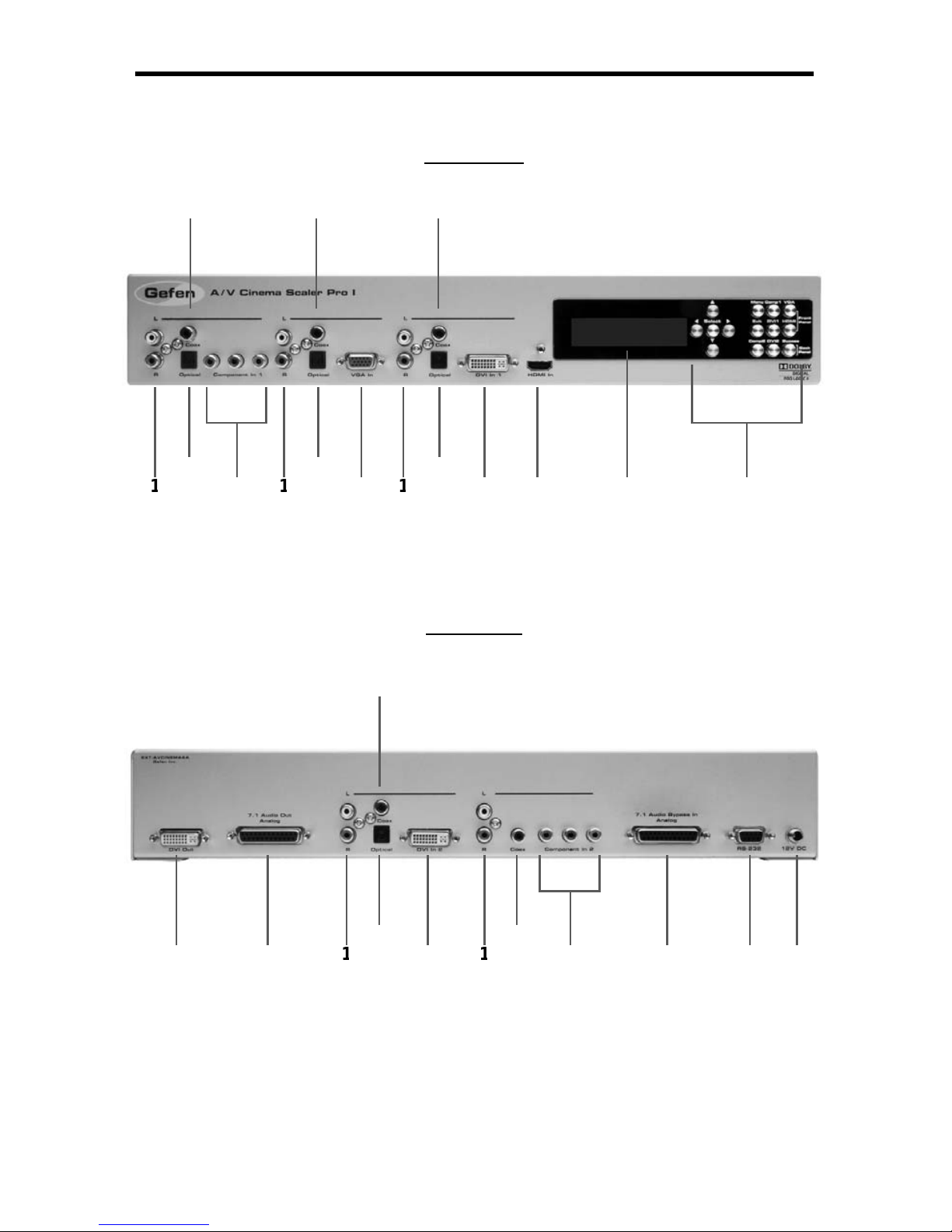
Front Panel
Back Panel
10
12
1
3
1
4
151
1
5
7
ANEL LAYOU
T

5
Analog L+R RCA Audio Inpu
t
This input will accept 2 channel analog audio using 1 pair of RCA analog audio
type connectors. There is a set of connectors available for all inputs except for
the HDMI and DB-25 inputs. For a listing of accepted audio formats please see
age 14.
Digital Optical Audio Input (TOSLINK)
This input will accept multi-channel digital audio using 1 optical type connector.
There is a connector available for all inputs except for the HDMI, Component 2,
and DB-25 inputs. For a listing of accepted audio formats, including supported
audio channels, please see page 14-15.
omponent Video Inpu
t
This input will accept component video (YPbPr) via 3 RCA type connectors.
There is one set of connectors located on the front and back panels. For a listing
of accepted resolutions please see page 13.
Digital Coaxial Audio Input (S/PDIF)
This input will accept multi-channel digital audio using 1 RCA type connector.
There is a connector available for all inputs except for the HDMI and DB-25
inputs. For a listing of accepted audio formats, including supported audio
hannels, please see page 14-15.
GA V ideo Inpu
t
This input will accept VGA video (RGBHV) via a HD-15 type connector. For a
isting of accepted resolutions please see page 13.
DVI-I Video Inpu
t
This input will accept DVI-I video (RGB analog or digital) via a DVI-I type
onnector. Input format is automatically determined. For a listing of accepted
esolutions please see page 13.
HDMI Inpu
t
This input will accept an HDMI (RGB,YCbCr) signal via an HDMI type A
onnector. Audio and video are both supported by this connector. For a listing of
accepted resolutions and audio formats please see page 13.
High Contrast LCD Displa
y
This display will show pertinent information for confi guration control and status.
For information on how to use this display please see page 12-19.
avigation and Input Selection Button
s
These buttons are used to select the desired input source. Navigation buttons
are also provided for easy user navigation and confi guration of features. Please
ee page 7 for more information.
ANEL DESCRIPTION
S

ANEL DESCRIPTION
S
DVI-D Outpu
t
This output will accept DVI-D (RGB digital) capable display device via a DVI-I
t
y
pe connector. This output port will support displays that are capable of
accepting the two output resolutions; 1080p and 2K.
7.1 Channel Analog Audio Outpu
t
This output will accept a DB-25 type connector to connect to a multi-channel
analog audio device. This port is always active. All audio from each input will be
onverted and output through this port. For pin-out information please see page
42-43.
2 DVI-D Inpu
t
This input will accept DVI-D video (digital) via a DVI-I type connector. Input
f
ormat is digital only. For a listing of accepted resolutions please see page 13.
7.1 Channel Analog Audio Inpu
t
This input will accept a DB-25 type connector for multi-channel analog audio
input. This port is only active when the bypass mode is selected (page 41). For
in-out information please see page 42-43.
S-232 Serial Control Interface
This port is used for serial communication for multiple functions. Access to
ertain features are only through the RS-232 interface.
2V DC Power Receptacle
This port will accept power via the included 12V DC power supply. This is a
ocking type connector.
7
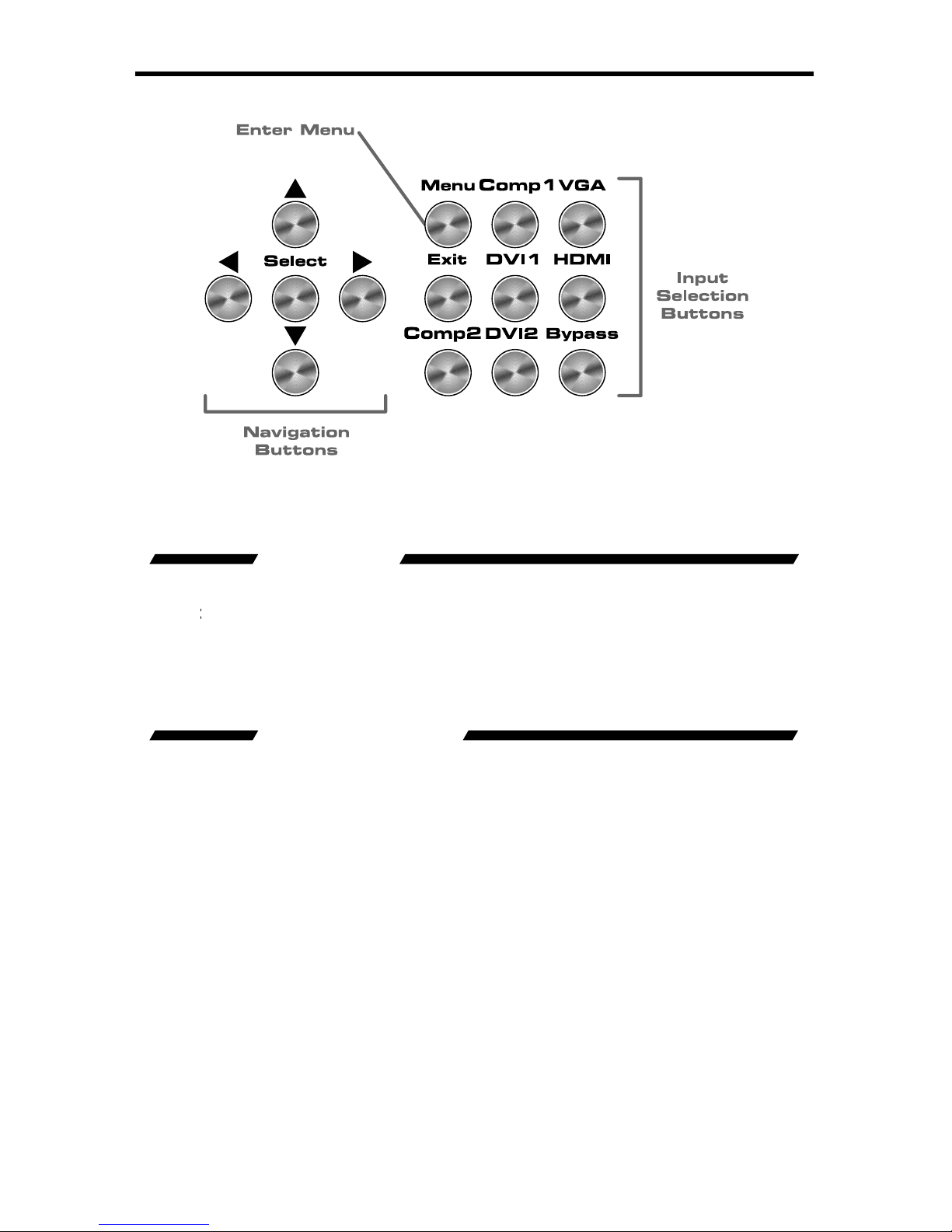
FRONT PANEL BUTTON
S
The front panel buttons are used for navigation, confi guration, and input selection.
The directional buttons (▲
►▼
are used to navigate the user menus system. The
butto
n is
used to confi
rm menu and item selections.
The
enu button is used to enter the con
fi g
uration menu .
The
xit button is used to exit the con
fi g
uration menu at any time.
The desired input port can be directly selected using the front panel input buttons.
imply press the desired input button. Source changing can take up to 10 seconds
longer when syncing digital video signals).
The bypass button will enable bypass mode (page 41).

CONNECTING AND OPERATING THE A/V CINEMA SCALER PRO
NSTALLING THE A/V CINEMA SCALER PR
O
onnect video source devices to the A/V Cinema Scaler Pro’s video inputs.
The
f
ollowing inputs are available
:
Front Panel
HDM
I
DVI-I (analog and digital DVI
)
VGA
C
omponen
t
Back Panel
DVI-D (digital DVI
)
C
omponen
t
NOTE:
2.
onnect audio sources to the A/V Cinema Scaler Pro’s audio inputs. The
f
ollowing inputs are available
:
Front Panel
DMI: Em
bedded audio
DVI-I: Analog RCA L+R or Digital TOSLINK or S/PDIF
C
omponent: Analog RCA L+R or Digital TOSLINK or S/PDIF
VGA: Analog RCA L+R or Digital TOSLINK or S/PDIF
Back Panel
DVI-D: Analog RCA L+R or Digital TOSLINK or S/PDIF
C
omponent: Analog RCA L+R or Digital S/PDIF
DB-25: Analog multi-channel audio. Please se
e
pa
g
e 42-43 for specifi c pin-out informatio
n
NOTE: All inputs, except
f
or HDMI, is able to accept both analog and digital
audio sources. Therefore, each input has a selector option in the OSD that will
allow the user to choose which type of audio is used.
.
onnect the DVI capable output device to the A/V Cinema Scaler Pro’s DVI-I
input.
NOTE: This output is a DVI-I connector. Analo
g
or digital type video can
be output through this connector. Selection of the output format can be
accomplished by using either the OSD (on-screen display) or the front panel
LCD and buttons. Please see page 17 for instructions on how to change the DVI
output type.
4.
onnect the analog DB-25 audio output to the analog DB-25 input on the
appropriate audio device.
.
onnect the included 12V power supply between the A/V Cinema Scaler Pro
and an open power socket. Ensure that the input cable is properly secured
to the unit.
SING THE A/V CINEMA SCALER PRO - MAIN LC
D
A/V CINEMA SCALER PRO - NAVIGATION
The A/V Cinema Scaler Pro uses a series of buttons, located on the front panel,
f
or all input selection and feature functions. All status information, such as
the input and output resolutions, are always available on the front panel
D
Screen
User adjustable features, such as color correction and aspect ratio, can
be navigated and adjusted by referencing either the
Screen or the
O
n-
creen Display
(
OS
D
.
All menu navigation and adjustments are accomplished by using the front panel
buttons. Please review the front panel buttons below.
For a full description of each of these buttons please see the descriptions on
age 7.
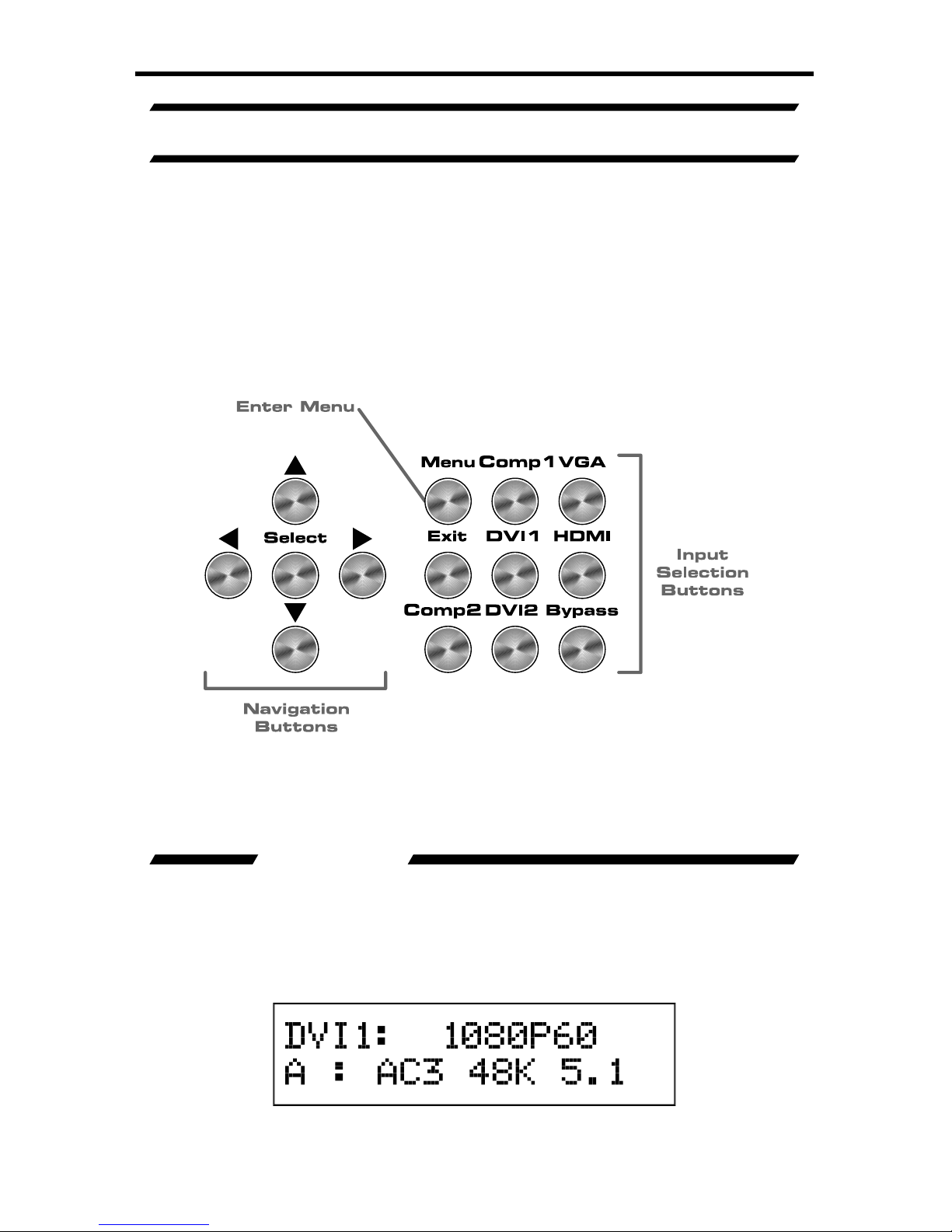
Th
e
CD Screen displa
y
s status information and can also be used to navigate
and adjust functions on the A/V Cinema Scaler Pro. This display is a high
ontrast 2-line/16-character LCD. It will display information like in the example
low.
ain Screen
10
SING THE A/V CINEMA SCALER PRO - MAIN LC
D
A/V CINEMA SCALER PRO - INITIAL STARTU
P
nce all video and audio connections have been made and the power supply
as been connected, the A/V Cinema Scaler Pro should automatically turn on.
The front panel LCD should indicate this by displaying the text
:
This screen should be displayed for 3 seconds while the system is booting. Once
this is complete, the
ain Screen should appear.
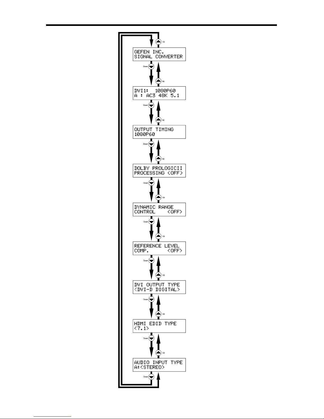
There are 7 different information panes that are available to provide the user with
l information. Th
ese are
the
roduct Titl
e
ain Screen
Output Screen,
Surround Processing, DVI Output Type, HDMI EDID Type, and Audio Input
p
e
information panes. Please use the
and
buttons to cycle through the
different information panes. The cycling order is displayed on the next page.
NOTE: Th
e
A
udio Input Type pane will not be available when the HDMI input is
lected.
roduct Titl
e
1
1
SING THE A/V CINEMA SCALER PRO - MAIN LC
D
roduct Titl
e
ain Screen
Output Screen
Surround Processing Screen
VI Output Type Screen
Reference Level Com
p
ensation
Screen
namic Range Control Screen
HDMI EDID Type Screen
Audio Input Type Screen
12
SING THE A/V CINEMA SCALER PRO - MAIN LC
D
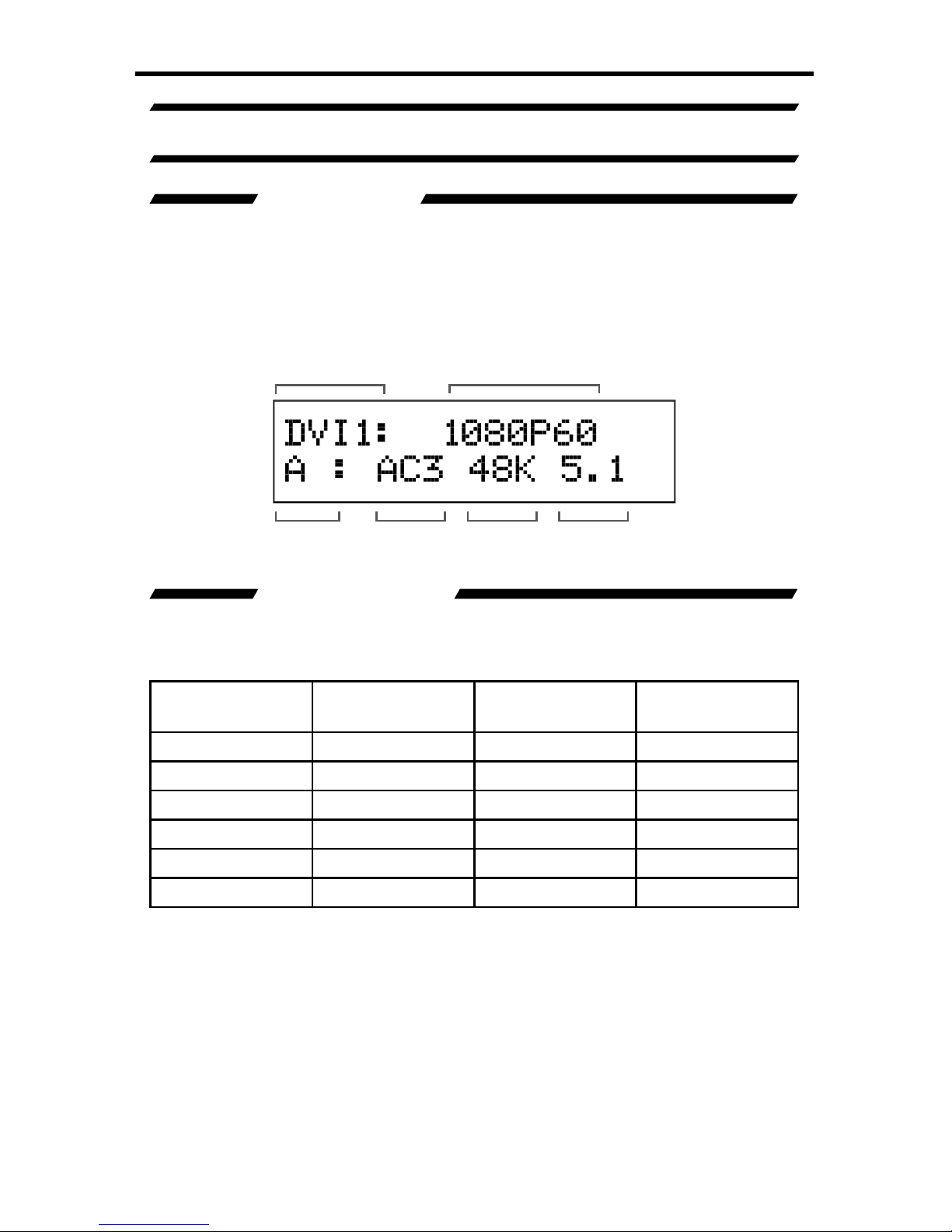
A/V CINEMA SCALER PRO - MAIN SCREEN
The
ain Screen will displa
y
useful information to the user. It displays the
urrently selected input port and audio input format. The currently used output
f
ormat can also be displayed by pressing the
button. Pressing the ◄ or ►
ttons while on this screen will have no
effec
t. Pl
ease see below fo
r the
ain
Screen
ayout.
This portion of the screen will display the currently selected input. The available
inputs, labels, and associated buttons are listed below
:
CD Displa
y
Nam
e
Actual Inpu
t
ocation
Front Panel
Button
MP
1
omponen
t
Front Panel
MP
1
P
C
VG
AFr
o
nt PanelV
G
A
DVI-D1
/
DVI-A
1
DVI-
I
Front Panel DVI
1
DMI
DMI Front Panel
DMI
MP
2
omponen
t
Back Panel
MP
2
DVI-D
2
DVI-D Back Panel DVI
2
Selected Input
Input Audio
Type
Audio
Format
Sampling
Rate
Number of
Channels
Input Resolution
ain Screen
 Loading...