

Page 1

3GSDI to
®
HDMI
1.3
Converter
EXT-3GSDI-2-HDMI1.3
User Manual
®
www.gefen.com
Page 2

ASKING FOR ASSISTANCE
Technical Support:
Telephone (818) 772-9100
(800) 545-6900
Fax (818) 772-9120
Technical Support Hours:
8:00 AM to 5:00 PM Monday thru Friday, Pacifi c Time
Write To:
Gefen, LLC.
c/o Customer Service
20600 Nordhoff St
Chatsworth, CA 91311
www.gefen.com
support@gefen.com
Notice
Gefen, LLC reserves the right to make changes in the hard ware, packaging and
any accompanying doc u men ta tion without prior written notice.
3GSDI to HDMI 1.3 Converter is a trademark of Gefen, LLC
HDMI, the logo, and High-Defi nition Multimedia Interface are
trademarks or registered trademarks of HDMI Licensing in the United States and
other countries.
© 2011 Gefen, LLC, All Rights Reserved
All trademarks are the property of their respective owners
Rev B8
Page 3

CONTENTS
1 Introduction
2 Operation Notes
3 Features
4 Panel Layout
5 Panel Descriptions
6 Bottom Panel Layout
7 Bottom Panel Descriptions
8 Connecting And Operating The 3GSDI To HDMI 1.3 Converter
9 DIP Switch Features
11 Firmware Update
15 Specifi cations
1 Warranty
Page 4

INTRODUCTION
Congratulations on your purchase of the 3GSDI to HDMI 1.3 Converter. Your
complete satisfaction is very important to us.
Gefen
Gefen delivers innovative, progressive computer and electronics add-on solutions
that harness integration, extension, distribution and conversion technologies.
Gefen’s reliable, plug-and-play products supplement cross-platform computer
systems, professional audio/video environments and HDTV systems of all sizes
with hard-working solutions that are easy to implement and simple to operate.
The Gefen 3GSDI to HDMI 1.3 Converter
The Gefen 3GSDI to HDMI 1.3 Converter will take any SDI, HD-SDI, or 3G-SDI
video signal and convert it to HDMI 1.3. The SDI input resolution will simply be
converted to an HDMI signal. DIP switches on the unit will allow the user to select
features such as Deep Color conversion and colorspace. A useful 720p (60Hz)
test pattern is also available, without connecting an SDI source, for checking the
HDMI video output. An SDI loop out and 2 channel analog audio outputs are also
provided for monitoring the input SDI source.
How It Works
The 3GSDI to HDMI 1.3 Converter will convert the input SDI signal (SD/HD/3G)
to an HDMI compatible signal. Connect the SDI source device to the video input
on the unit. Connect an HDMI compatible device on the video output on the unit.
Adjust DIP switch features and connect the power supply. It’s that simple.
1
Page 5
OPERATION NOTES
READ THESE NOTES BEFORE INSTALLING OR
OPERATING THE 3GSDI TO HDMI 1.3 CONVERTER
• Supports the following SMPTE standards: 259M, 292M, SMPTE 274M,
SMPTE 296M, ITU-R BT.656 and ITU-R BT.601
• Handles 3G-SDI SMPTE 425-A and 425-B / formats 1080P 50/59.94/60.
• Support of 4 stereo 48 kHz audio streams.
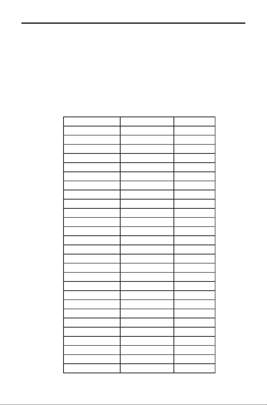
• The 3GSDI to HDMI 1.3 Converter supports the following resolutions:
Video Resolution Refresh Rate (Hz) Rate
525i (NTSC) (480i) 59.94 SD
525p (480p) 59.94 SD
525p (480p) 60 SD
625i (PAL) (576i) 50 SD
625p (576p) 50 SD
720p 23.98 HD
24 HD
25 HD
29.97 HD
30 HD
50 HD
59.94 HD
60 HD
1080i 50 HD
59.94 HD
60 HD
1080p 23.98 HD
24 HD
25 HD
29.97 HD
30 HD
50 3G lev.A/B
59.94 3G lev.A/B
60 3G lev.A/B
2K 23.97 HD
24 HD
25 HD
2
Page 6

FEATURES
Features
• Field upgradable fi rmware using the built-in USB port.
• Supports a test pattern at 720P/60 without needing a valid source signal
• HMDI 1.3 compliant
• Support for YCbCr, RGB, 4:2:2, 4:4:4, and 8 to 10 bits output formats.
• Color space support: YCbCr, RGB.
• Color sampling: 4:2:2 and 4:4:4.
• Bit depth: 8, 10 bits.
• Auto-detects optimal monitor format with EDID display capability information.
• Support of 4 stereo 48 kHz audio streams.
• Supports up to 8 channels of PCM audio embedded into the HDMI output
signal
• Supports Dolby Digital/DTS AC3 encoded audio
• Automatic detection of SD, HD and 3G-SDI formats on the input
• A re-clocked copy of the SDI input is available on the output SDI connector.
• Audio from SDI input channels 1 & 2 can be monitored through 3.5mm ministereo RCA-jack analog audio connectors
Package Includes
(1) 3GSDI to HDMI 1.3 Converter
(1) 5V DC Locking Power Supply
(1) User Manual
3
Page 7
PANEL LAYOUT
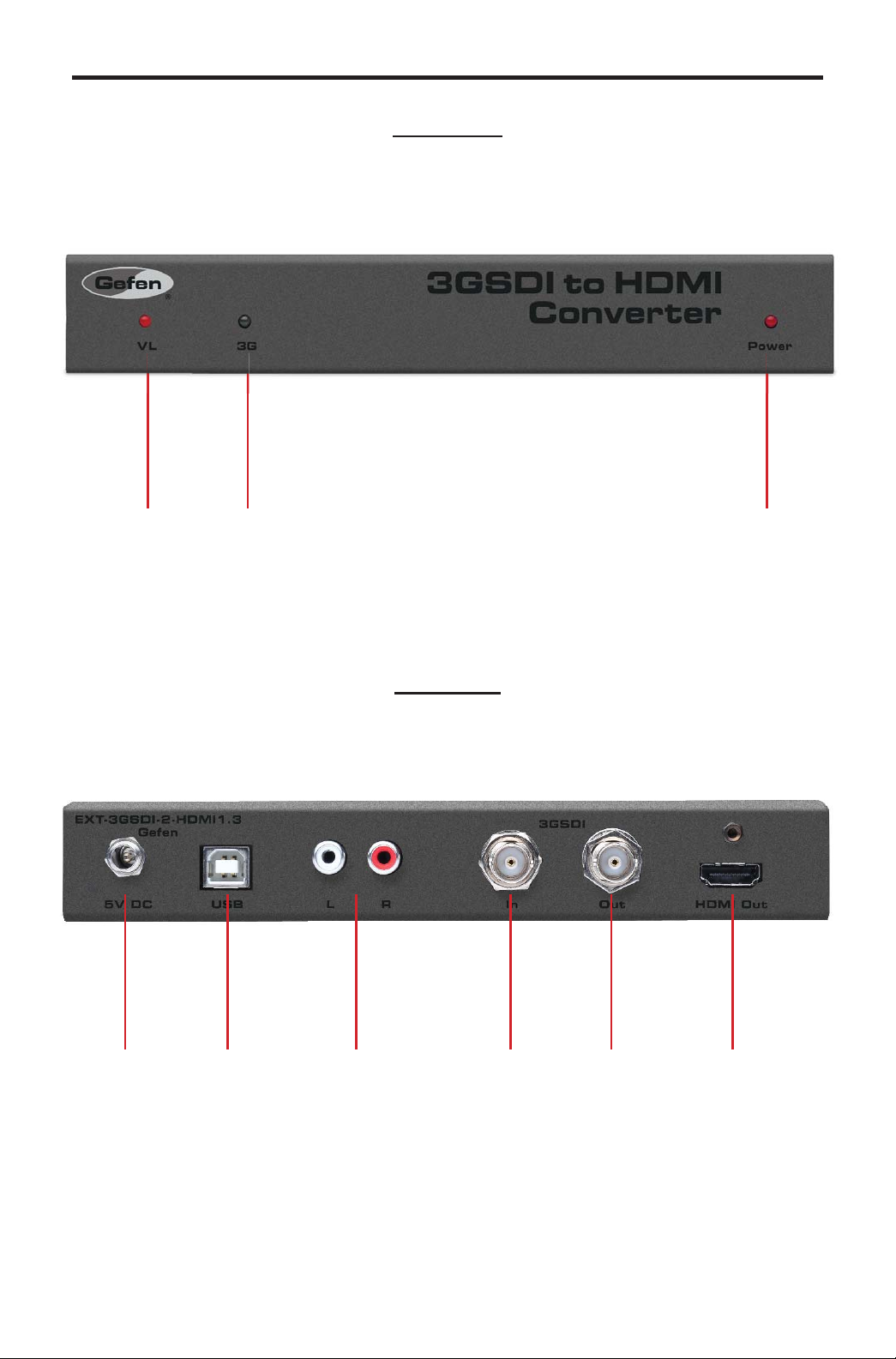
Front Panel
1 2 3
Back Panel
4 5 6 7 8 9
4
Page 8

PANEL DESCRIPTIONS
1 Video Lock LED Indicator
This indicator will become active when the SDI input (SD/HD/3G) is locked.
2 3G LED Indicator
This indicator will become active when the SDI input is a 3G source.
3 Power LED Indicator
This indicator will become active when power is being supplied to the unit via the
included 5V DC power adapter.
4 Locking 5V DC Power Receptacle
This input will accept power via the included locking 5V DC power supply .
Connect the power supply between this input and an open wall power socket.
5 USB Update Port
This port is used to update fi rmware. For current fi rmware releases please see
the download section at www.gefen.com.
6 Analog RCA Audio Ouput
This input will output up to 2 channels of analog audio via 2 RCA style analog
audio connectors. This audio will be extracted from the incoming SDI source for
monitoring purposes.
7 SDI Input
This input will accept a single SDI video source. For acceptable input formats
please see page 2.
8 SDI Loop Output
This output will mirror the input SDI video source. This is useful for monitoring
the SDI input source.
9 HDMI Ouput
This output will accept a single HDMI type A male cable. The converted SDI
signal will be output through this port. Audio and video are both supported by
this port. For a complete listing of the acceptable SDI, audio and video formats
please see page 2.
5
Page 9

BOTTOM PANEL LAYOUT
Bottom Panel
12 3
4567
6
Page 10

BOTTOM PANEL DESCRIPTIONS
1 SDI Input Color Sampling LED Indicator
This LED indicator will relay the status of the incoming SDI input’s color
sampling. Options are either 4:4:4 (LED ON) or 4:2:2 (LED OFF).
2 SDI Input Color Space LED Indicator
This LED indicator will relay the status of the incoming SDI input’s color space.
Options are either RGB (LED ON) or YCbCr (LED OFF).
3 Confi guration DIP Switches
This DIP (Dual In-line Packages) switches will enable disable features on the
3GSDI to HDMI 1.3 Converter. For a complete listing of DIP switch features and
functions please see page 9.
4 SDI Input Color Depth LED Indicator
This LED indicator will relay the status of the incoming SDI input’s color depth.
Options are either 12 bit (LED ON) or 8/10 bit (LED OFF).
5 HDMI Output Color Space LED Indicator
This LED indicator will relay the status of the outgoing HDMI output’s color
space. Options are either YCbCr (LED ON) or RGB (LED OFF).
6 HDMI Output Color Sampling LED Indicator
This LED indicator will relay the status of the outgoing HDMI output’s color
sampling. Options are either 4:4:4 (LED ON) or 4:2:2 (LED OFF).
7 HDMI Output Deep Color LED Indicator
This LED indicator will relay the status of Deep Color in the HDMI’s output.
Options are either Deep Color ON (LED ON) or Deep Color OFF (LED OFF).
7
Page 11

CONNECTING AND OPERA TING THE 3GSDI TO HDMI 1.3 CONVERTER
Co
How to Connect the 3GSDI to HDMI 1.3 Converter
1. Connect the SDI source (SD/HD/3G) to the SDI input on the 3GSDI to HDMI
1.3 Converter using a user supplied SDI cable.
2. Optionally, connect an SDI capable output device to the SDI loop out
connector for monitoring of the SDI input signal.
3. Optionally connect a 2 channel analog audio device to the 2 RCA style
analog audio connectors for monitoring of the audio from the SDI input.
4. Connect an HDMI capable output device to the HDMI output port on the
3GSDI to HDMI 1.3 Converter using a user supplied HDMI cable.
NOTE: By default, the features in the EDID of the sink device are used to
confi gure the output color space, sampling, and bit depth. These features can be
overridden by adjusting the DIP switches on the bottom panel of the 3GSDI to
HDMI 1.3 Converter. Please see page 9 for more information.
5. Connect included 5V DC power supply to the locking power receptacle of the
3GSDI to HDMI 1.3 Converter and an open wall power socket.
Wiring Diagram for the Gefen 3GSDI to HDMI 1.3 Converter
ANALOG AUDIO (RCA) CABLE
3G-SDI CABLE
3GSDI Source
Converter
Powered
Speakers
HDMI CABLE
HD Display
8
Page 12

DIP SWITCH FEATURES
The 3GSDI to HDMI 1.3 Converter has a series of DIP switches that will allow
manual confi guration of the HDMI’s output video signal. There is also a DIP
switch to display a test pattern through the HDMI output. Please see the next
page for DIP switch features and operation.
Switch Description
1 Test pattern Off On
2 EDID Auto Manual
3
4
5
6
7
8 Spare Unused N/A N/A
1 The color bar test pattern is in 720p (60Hz) format. No valid input is
necessary at the SDI connector to use the test pattern.
HDMI Out
Sampling
HDMI Out Color
Space
HDMI Out RGB
Range
HDMI Out Deep-
Color
HDMI Out Bit
Depth
(Factory Default)
OFF
4:4:4 4:2:2
RGB YCbCr
Limited Full
Off Deep
12b 10b
On
2 When this switch is turned OFF (Auto), the HDMI output is confi gured
according to what is reported inside the HDMI sink EDID connected to the
mini converter. When turned ON(Manual), the switches 3 to 7 are used
instead for the confi guration of the HDMI link.
9
Page 13

DIP SWITCH FEATURES
3 When the EDID switch is ON (set to manual), this switch sets the output
sampling of the video: 4:2:2 or 4:4:4.
4 When the EDID switch is ON (set to manual), this switch sets the output
color space of the video: YCbCr or RGB.
5 When the EDID switch is ON (set to manual), and the HDMI output color
is RGB, this switch specifi es the video range: limited (16-235) or full range
(0-255).
6 When the EDID switch is ON (set to manual), this switch forces the output
into Deep Color,12-bits or into 8 bits.
7 When the EDID switch is ON (set to manual) and DIP switch 6 is set to ON
(Deep Color), this switch forces the output into 10-bit or 12-bit.
LED INDICATORS
10
Page 14

FIRMWARE UPDATE
Things you’ll need:
• Computer running Windows XP or Vista
• 3GSDI Converter Firmware Loader 1.1.18 software
• USB cable (to-male)
• Firmware fi les contained in 3GSDI To HDMI Converter Firmware 1.1.5
1. Download 3GSDI Converter Firmware Loader 1.0.18 from
http://www.gefen.com/kvm/support/download.jsp
a. Create a new folder and decompress the downloaded fi le
Mini_Updater_Release_1_0_18.zip into the newly created folder.
b. Read and follow instructions on the Installation Guide.txt for installing
the fi rware loader software.
2. Connect the USB cable between your PC and the EXT-3GSDI-2-HDMI1.3
a. Check Device Manager on Windows to fi nd the correct COM port
number for the USB connection. Remember this COM port number
for use in step #4.
11
Page 15

FIRMWARE UPDATE
3. Download and decompress 3GSDI to HDMI Converter Firmware 1.1.5 from
http://www.gefen.com/kvm/support/download.jsp to the new folder created in
Step #1.
4. After installing the Firmware Loader described in Step #2, run the
program via the Windows Start Menu….Start/Programs/Gefen/Mini Updater/
Mini Updater.
a. Use the drop-down arrow to choose the COM port shown in Step #2.
5. Browse for the fi le
Mini3GSDI_TO_HDMI_1_1_5.ini
in the new folder created in Step#1
6. Once the fi le is found, click Update Device.
12
Page 16

FIRMWARE UPDATE
7. After pressing Update Device, you should see this window confi rming the
correct COM port, the detected device, and the fi rmware binary fi le.
8. Another window will pop-up showing the fi rmware loader program doing a
communication check
13
Page 17

FIRMWARE UPDATE
9. If all steps are PASS, the fi rmware upload process can continue. Click YES to
continue the update. If there is a FAIL, repeat steps #2-7.
10. After clicking YES, this window will appear twice showing th upload progress.
11. Once the upload process is complete, another window will pop up showing
the message “Update fi nished”.”.
14
Page 18

SPECIFICATIONS
Max. image output resolutions: ............................2K (2048x1080), 1920x1080/60
Input Connector: ...........................................(1) BNC female SDI/HD-SDI/3G-SDI
Input Connector: ............................................(1) Locking 5V DC power connector
Input Connector: ..................................(1) USB connector (for fi rmware upgrades)
Output Connector: ...........(1) BNC female SDI/HD-SDI/3G-SDI (w/buffered input)
Output Connector: ..............................................(1) HDMI 1.3 Type A 19-pin Male
Output Connectors: ...................................(2) L+R analog audio jacks (RCA-type)
Input Video Bandwidth: .................................up to 3.0 Gbps (Single Link 3G-SDI)
Output Video Bandwidth: ....................................225 MHz (Single Link HDMI 1.3)
SDI Compliant: .......................................................SMPTE 259M, up to 360 Mb/s
HD-SDI Compliant ..............................................SMPTE 292M, up to 1.485 Gbps
3G-SDI Compliant..........................................SMPTE 424M/425M, up to 3.0 Gbps
Power Supply: .......................................................5V DC locking type, 2.5W each
Dimensions: ........................................................................8.2’’ W x 1.1’’H x 7.5’’D
Rack Size: ........................................................................................1U (half-width)
Operating Temp.: ............................................................................0-40 degrees C
Shipping Weight ............................................................................................. 4 lbs
HDMI 1.3 Compliant
16
Page 19

Gef
en warrants the equipment it manufactures to be free from defects in material
f
y
e
e
f
eff
y of
y
y
f of
g
f
Gef
y
g
y
g
y
p
N
g
and workmanship.
I
equipment fails because of such defects and Gefen is notifi ed within two (2)
ears from the date of shipment, Gefen will, at its option, repair or replace the
quipment, provided that the equipment has not been subjected to mechanical,
lectrical, or other abuse or modifi cations. Equipment that fails under conditions
other than those covered will be repaired at the current price o
ect at the time of repair. Such repairs are warranted for ninety (90) days from
the da
reshipment to the Buyer.
parts and labor in
This warrant
without limitation, an
articular purpose, all of which are expressly disclaimed.
1. Proo
2.
The in
be accurate. However,
that ma
direct, indirect, special, incidental, or consequential dama
an
dama
For the latest warrant
ustomers outside the US are responsible for shipping charges to and from
efen.
.
opper cables are limited to a 30 day warranty and cables must be in their
ori
ormation in this manual has been carefully checked and is believed to
defect or omission in this manual, even if advised of the possibility of such
es. The technical information contained herein regarding the features and
pecifi cations is subject to change without notice.
age at http://www.gefen.com/kvm/aboutus/warranty.js
is in lieu of all other warranties expressed or implied, including
implied warranty or merchantability or fi tness for any
sale may be required in order to claim warranty.
inal condition.
en assumes no responsibility for any inaccuracies
be contained in this manual. In no event will Gefen be liable for
es resulting from
coverage information, please visit Gefen’s Warranty web
RODUCT REGISTRATIO
lease register your product online by visiting Gefen’s web site at
http://www.
efen.com/kvm/Registry/Registration.jsp
17
Page 20

Page 21

Page 22

Rev B8
20600 Nordhoff St., Chatsworth CA 91311
1-800-545-6900 818-772-9100 fax: 818-772-9120
www.gefen.com support@gefen.com
Pb
This product uses UL listed power supplies.
 Loading...