

Page 1

DVI
Detective
Plus
EXT-DVI-EDIDP
User Manual
®
Page 2

Technical Support:
Telephone (818) 772-9100
(800) 545-6900
Fax (818) 772-9120
Technical Support Hours:
8:00 AM to 5:00 PM Monday thru Friday.
Write To:
Gefen Inc.
C/O Customer Service
20600 Nordhoff St.
Chatsworth, CA 91311
support@gefen.com
www.gefen.com
Notice
Gefen Inc. reserves the right to make changes in the
hard ware, packaging and any accompanying doc u men ta tion
without prior written notice.
The DVI Detective Plus is a trademark of Gefen Inc.
© 2009 Gefen Inc., All Rights Reserved
All trademarks are the property of their respective companies.
ASKING FOR ASSISTANCE
Rev A3
Page 3

TABLE OF CONTENTS
1 Introduction
2 Features
3 Panel Layout
4 Connecting and Operating the DVI Detective Plus
5 Connecting and Operating the DVI Detective Plus
6 Using a Pre-Programmed EDID
9 Pre-Programmed EDID Diagram
10 Write Protecting the DVI Detective Plus
11 Specifi cations
12 Warranty
Page 4

INTRODUCTION
Computers and HDTV video source devices
can sometimes lose the EDID -- the electronic
identifi cation of a display which lists its possible
resolutions and frequencies. When displays
are switched away or disconnected and then
reconnected, the EDID can be lost and the computer
or HD video source device can lose the ability to
display the image properly. The DVI Detective Plus
captures a display device’s EDID and stores it.
How It Works
Simply program the DVI Detective Plus for
the display that you will use by performing a
programming step while having the device connected
to the display and a power adapter. Next put it into
place on the video output of your video source
and restart your equipment. When all sources and
displays are powered on, seamless functioning of
video source and display equipment will commence.
External buttons make EDID programming and
settings operations a breeze -- formerly, some
operations could require opening the unit.
1
Page 5

FEATURES
Features
• Store EDID information for displays
• Supports resolutions up to 1920x1200, 2K, and
3840x2400 (Dual Link)
• Keeps computer systems from deactivating
inactive DVI ports
• Can eliminate CAT-5 lines used to carry DDC
signals when extending computer video
• Passes HDCP copy-protection protocols for
full HDTV, using an HDMI to DVI adapter (not
included)
• No power required after initial programming
Includes:
(1) DVI Detective Plus
(1) 1’ DVI cable (m-m)
(1) 5V DC Power Supply
(1) User’s Manual
Note: the supplied DVI-D cable does not support
analog VGA.
2
Page 6
3
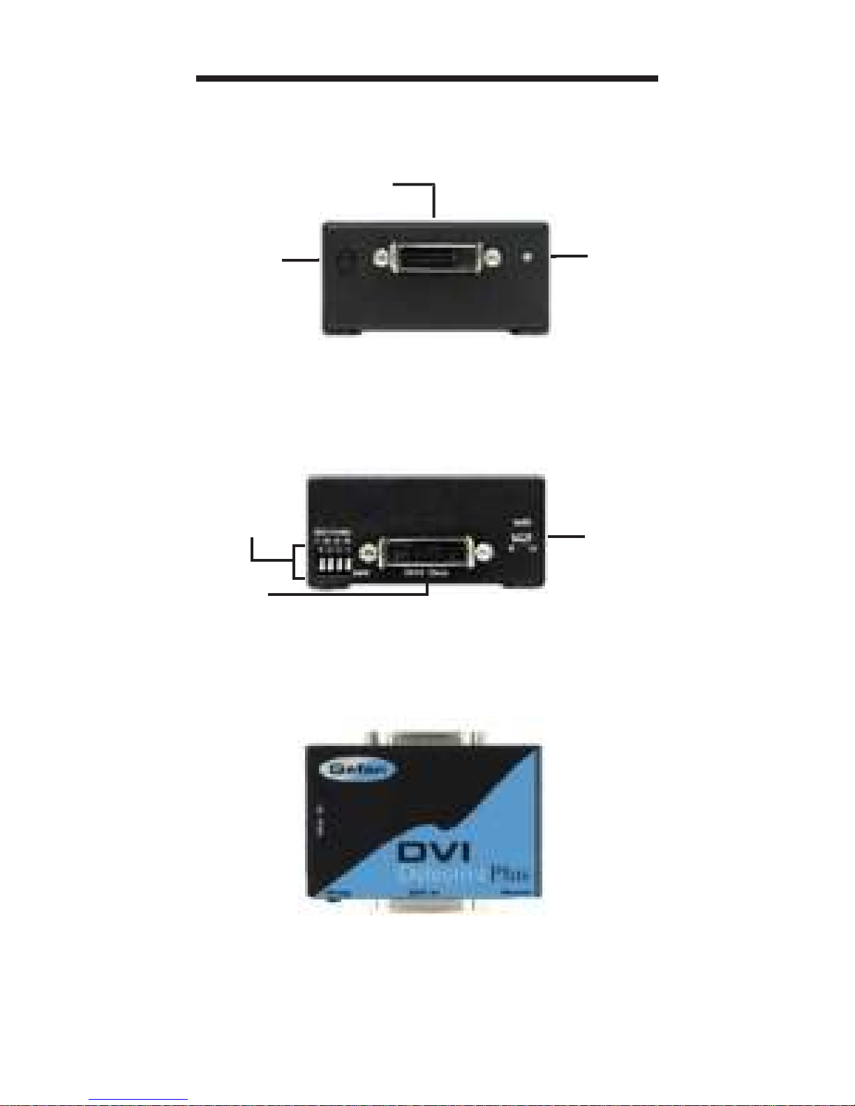
PANEL LAYOUT
Front Panel
Back Panel
Write
Protection
Switch
EDID &
HDCP
Switches
DVI
Out
Power
LED
Indicator
Programming
Button
DVI
In
Back
Front
Page 7

CONNECTING AND OPERATING
THE DVI DETECTIVE PLUS
1. Before proceeding, please ensure that the
write protect switch is in the E (write enabled)
position and all SETTING DIP SWITCHES
are in the OFF (down) position Please see the
diagram on the page 8.
2. Connect the display to the DVI Out port on
the DVI Detective Plus. Turn on the display to
ensure that an EDID is being transmitted.
3. Plug the supplied 5V DC power supply into the
DVI Detective Plus. The power LED should
be glowing either solid RED (an EDID is not
programmed) or solid GREEN (an EDID is
properly programmed).
4. Once you are ready to program the EDID,
press and hold the Program button on the front
panel of the DVI Detective Plus until the unit’s
LED begins to rapidly fl ash green. Once the
recording sequence is initiated, release the
button and wait until the LED glows a solid
green color. A successful EDID programming
sequence is indicated with a green LED while
an unsuccessful EDID record is indicated with
a red LED.
NOTE: If the unit does not initiate the recording
sequence (indicated by a fl ashing green LED),
please unplug the display and 5V DC power supply
from the unit and repeat steps 2 and 3. If a solid red
LED is indicated after several unsuccessful recording
attempts, it is possible that the EDID recorded from
the display is bad. Please refer to the section, USING
A PRE-PROGRAMMED EDID on page 6 and 7 for
instructions on how to use one of the built in EDIDs.
4
Page 8

5
CONNECTING AND OPERATING
THE DVI DETECTIVE PLUS
5. Once a successful EDID record is complete,
remove the 5V DC power supply from the DVI
Detective Plus. At this time, it is recommended
that you write protect the DVI Detective Plus
to prevent an accidental overwrite. Please see
page 9 for instructions on this procedure.
6. If HDCP is required by the source, the display
must also be HDCP compliant and DIP
SWITCH 4 will have to be enabled for HDCP
pass through to function. Please refer to
your source and display manuals for HDCP
compatibility and enable DIP SWITCH 4
appropriately.
7. The source should be powered off when
connecting it to the DVI In port on the DVI
Detective Plus.
8. Power on the source.
Note: If using a PC, restart your computer only after
you’ve made all the connections.
Page 9

USING A
PRE-PROGRAMMED EDID
The DVI Detective Plus includes 5 built-in manuallyselectable generic EDIDs (display identities) for
forcing several standard home theater setups with
multi-channel audio and standard HDTV resolutions.
This functionality is vital when equipment reaches a
state of indeterminate function and will not respond to
signals or controls properly, and a certain resolution
size with specifi c audio must be forced upon all
connected equipment. On the next two pages are
tables with the listed resolutions, refresh rates, and
audio channels for each pre-programmed EDID.
Once the desired EDID is chosen, use the steps
below to program the DVI Detective Plus.
1. Choose the desired EDID from the table above
and enable the corresponding DIP SWITCHES.
2. Remove any DVI cables and power supplies
attached to the DVI Detective Plus.
3. Follow steps 3 through 8 in the section
CONNECTING AND OPERATING THE DVI
DETECTIVE PLUS (Page 4 and 5)
NOTE: Only when the DIP SWITCHES are set in
the combinations above will an pre-programmed
EDID be written to the DVI Detective Plus. Please
set all DIP SWITCHES to the OFF (down) position to
enable the default setting and record an EDID from
an attached display.
6
Page 10

USING A
PRE-PROGRAMMED EDID
7
EDID Resolutions - Aspect Ratio Refresh Rate Audio Setting DIP SWITCHES
1
720 x 576p 4:3 720 x 576p 16:9
50 hz
Linear PCM 2
Channel
1234
1280 x 720p 16:9 1920 x 1080p 16:9
ON OFF OFF N/A
1920 x 1080i 16:9 (native)
2
720 x 480p 16:9 1440 x 480p 16:9
59.94/60 hz
Linear PCM 2
Channel
1234
1280 x 720p 16:9 1920 x 1080p 16:9
OFF ON OFF N/A
1920 x 1080i 16:9 (native)
3
720 x 576p 4:3 720 x 576p 16:9
50 hz
Linear PCM 8
Channel
1234
1280 x 720p 16:9 1920 x 1080p 16:9
ON ON OFF N/A
1920 x 1080i 16:9 (native)
Page 11

EDID Resolutions - Aspect Ratio Refresh Rate Audio Setting DIP SWITCHES
4
720 x 480p 16:9 1440 x 480p 16:9
59.94/60 hz
Linear PCM 8
Channel
1234
1280 x 720p 16:9 1920 x 1080p 16:9
OFF OFF ON N/A
1920 x 1080i 16:9 (native)
5
720 x 480p 16:9 1440 x 480p 16:9
59.94/60 hz
Linear PCM 2
Linear PCM 8
Linear DTS
Linear AC-3
1234
1280 x 720p 16:9 1920 x 1080i 16:9
ON OFF ON N/A
1920 x 1080p 16:9 (native)
USING A
PRE-PROGRAMMED EDID
8
Page 12

PRE-PROGRAMMED
EDID DIAGRAM
9
Pre-Programmed
EDID DIP SWITCHES
The EDID switches on the left hand side of
the unit are preset at the factory to provide the
behavior shown in the chart on Page 8. This behavior can be custom fi ne-tuned to accomodate
your audio/video displays by setting the small
white plastic switches as shown in the chart.
When adjusting the switches, please use gentle
force. A small pointed object such as a ballpoint
pen tip or a mechanical pencil head is desirable
when changing the position of the switches.
Page 13

Once the DVI Detective is programmed and working,
you can write protect the unit to prevent an accidental
overwrite. This is done by simply moving the write
protect switch to the D (write disabled) position. By
default, the unit is shipped in the E (write enabled)
position. This is done so that the unit is ready to
be programmed right out of the box. Whenever the
unit is going to be programmed, make sure that the
switch is in the “E” position, otherwise the procedure
will not work. The power LED will fl ash in alternating
green and red colors to indicate that the DVI
Detective Plus is currently write protected.
10
WRITE PROTECTING THE
DVI DETECTIVE
Write protection
switch
Page 14

11
Video Amplifi er Bandwidth ........................... 165 MHz
Maximum Range ........................ 1920 x 1200 x 60hz
DVI Input/Output Connector .............................. DVI-I
Power Consumption ........................... 5 Watts (max.)
Power Supply ................................................... 5VDC
Dimensions .......................... 2.6” W x 1.3” H x 1.7” D
Shipping Weight ................................................ 1 Lb.
SPECIFICATIONS
Page 15

Gefen Inc. warrants the equipment it manufactures to be free
from defects in material and workmanship.
If equipment fails because of such defects and Gefen Inc. is
notifi ed within two (2) year from the date of shipment, Gefen Inc.
will, at its option, repair or replace the equipment, provided that
the equipment has not been subjected to mechanical, electrical,
or other abuse or modifi cations. The two year warranty is only
valid on new products purchased as of January 2007. All products
purchased before this date still retain their 1 year warranty.
Equipment that fails under conditions other than those covered
will be repaired at the current price of parts and labor in effect
at the of repair. Such repairs are warranted for ninety (90) days
from the day of reshipment to the Buyer.
This warranty is in lieu of all other warranties expressed or
implied, including without limitation, any implied warranty or
merchantability or fi tness for any particular purpose, all of which
are expressly disclaimed. Please note that:
1. Proof of sale may be required in order to claim warranty.
2. Customers outside the US are responsible for shipping
charges to and from Gefen.
3. Copper cables are limited to a 30 day warranty and cables
must be in their original condition.
For the latest warranty coverage information, please visit
Gefen’s Warranty page at http://www.gefen.com/kvm/aboutus/
warranty.jsp
PRODUCT REGISTRATION
Please register your product online by visiting Gefen at:
http://www.gefen.com/kvm/Registry/Registration.jsp
The information in this manual has been carefully checked and
is believed to be accurate. However, Gefen Inc. assumes no
responsibility for any inaccuracies that may be contained in this
manual. In no event will Gefen Inc., be liable for direct, indirect,
special, incidental, or consequential damages resulting from any
defect or omission in this manual, even if advised of the possibility
of such damages. The technical information contained herein
regarding the DVI Detective Plus features and specifi cations is
subject to change without notice.
WARRANTY
12
Page 16

Page 17

Page 18

* ma - DVI - EDI DP*
20600 Nordhoff Street
Chatsworth CA 91311
1-800-545-6900 818-772-9100
fax: 818-772-9120
www.gefen.com
support@gefen.com
Rev A3
Pb
 Loading...