

Page 1
Audio
Embedder
3GSDI
Release A7
User Manual
EXT-DVI-1500HD
DVI 1500HD
Page 2

DVI 1500HD
Important Safety Instructions
ii
GENERAL SAFETY INFORMATION
1. Read these instructions.
2. Keep these instructions.
3. Heed all warnings.
4. Follow all instructions.
5. Do not use this product near water.
6. Clean only with a dry cloth.
7. Do not block any ventilation openings. Install in accordance with the manufacturer’s
instructions.
8. Do not install or place this product near any heat sources such as radiators, heat
registers, stoves, or other apparatus (including ampliers) that produce heat.
9. Do not defeat the safety purpose of the polarized or grounding-type plug. A polarized
plug has two blades with one wider than the other. A grounding type plug has two
blades and a third grounding prong. The wide blade or the third prong are provided for
your safety. If the provided plug does not t into your outlet, consult an electrician for
replacement of the obsolete outlet.
10. Protect the power cord from being walked on or pinched particularly at plugs,
convenience receptacles, and the point where they exit from the apparatus.
11. Only use attachments/accessories specied by the manufacturer.
12. To reduce the risk of electric shock and/or damage to this product, never handle or
touch this unit or power cord if your hands are wet or damp. Do not expose this
product to rain or moisture.
13. Unplug this apparatus during lightning storms or when unused for long periods of time.
14. Refer all servicing to qualied service personnel. Servicing is required when the
apparatus has been damaged in any way, such as power-supply cord or plug is
damaged, liquid has been spilled or objects have fallen into the apparatus,
the apparatus has been exposed to rain or moisture, does not operate normally,
or has been dropped.
15. Batteries that may be included with this product and/or accessories should never be
exposed to open ame or excessive heat. Always dispose of used batteries
according to the instructions.
Page 3

DVI 1500HD
Warranty Information
Gefen warrants the equipment it manufactures to be free from defects in material and
workmanship.
If equipment fails because of such defects and Gefen is notied within two (2) years from
the date of shipment, Gefen will, at its option, repair or replace the equipment, provided
that the equipment has not been subjected to mechanical, electrical, or other abuse or
modications. Equipment that fails under conditions other than those covered will be
repaired at the current price of parts and labor in effect at the time of repair. Such repairs
are warranted for ninety (90) days from the day of reshipment to the Buyer.
This warranty is in lieu of all other warranties expressed or implied, including without
limitation, any implied warranty or merchantability or tness for any particular purpose, all of
which are expressly disclaimed.
1. Proof of sale may be required in order to claim warranty.
2. Customers outside the US are responsible for shipping charges to and from Gefen.
3. Copper cables are limited to a 30 day warranty and cables must be in their original
condition.
The information in this manual has been carefully checked and is believed to be accurate.
However, Gefen assumes no responsibility for any inaccuracies that may be contained
in this manual. In no event will Gefen be liable for direct, indirect, special, incidental, or
consequential damages resulting from any defect or omission in this manual, even if
advised of the possibility of such damages. The technical information contained herein
regarding the features and specications is subject to change without notice.
For the latest warranty coverage information, refer to the Warranty and Return Policy under
the Support section of the Gefen Web site at www.gefen.com.
PRODUCT REGISTRATION
Please register your product online by visiting the Register Product page under the
Support section of the Gefen Web site.
iii
Page 4

iv
DVI 1500HD
Gefen, LLC
c/o Customer Service
20600 Nordhoff St.
Chatsworth, CA 91311
Telephone: (818) 772-9100
(800) 545-6900
Fax: (818) 772-9120
Email: support@gefen.com
Visit us on the Web: www.gefen.com
Technical Support Hours: 8:00 AM to 5:00 PM Monday - Friday, Pacic Time
DVI 1500HD is a trademark of Gefen, LLC.
Important Notice
Gefen, LLC reserves the right to make changes in the hardware, packaging, and any
accompanying documentation without prior written notice.
© 2011 Gefen, LLC. All Rights Reserved.
All trademarks are the property of their respective owners.
Contacting Gefen Technical Support
iv
Page 5

vv
3GSDI Audio Embedder
• 50 or 62.5 micron multimode ber optic cable is required for operation of the
DVI 1500HD.
• Maximum extension range of 330 feet (100 meters) when the source requires HDCP.
One CAT-5, CAT-5e or CAT6 cable is used to transmit DDC and HDCP data back to
the source.
• Maximum range of 1650 feet (500 meters) when the source does not require HDCP.
This scenario does not require the CAT-5, CAT5e or CAT-6 cable if the source does
not require DDC information. If DDC is required, the use of an EDID storage device
(Gefen part no. EXT-DVI-EDIDN or EXT-DVI-EDIDP) can be used to transmit DDC
information back to the source.
• Compatible with all DVI and HDMI (when used with a HDMI-to-DVI adapter) displays.
Operating Notes
DVI 1500HD
Page 6

vi
Features
• Extends any DVI device without HDCP up to 1650 feet (500 meters)
• Extends any DVI device with HDCP up to 330 feet (100 meters) (requires additional
CAT-5e cable)
• Supports resolutions up to 1920 x 1200
• Uses a four-strand multimode LC-LC ber optic cable
• Uses one CAT-5e cable for DDC and control signals
• Eliminates computer noise at your workstation
• Supports DDWG standard for DVI-compliant monitors
• HDCP compliant (maximum distance is 330 feet with HDCP)
• Rack-mountable
Packing List
The DVI 1500HD ships with the items listed below. If any of these items are not present in
your box when you rst open it, immediately contact your dealer or Gefen.
• 1 x DVI 1500S Sender Unit
• 1 x DVI 1500R Receiver Unit
• 2 x 5V DC Power Supply with locking connector
• 1 x 6 ft. DVI cable (M-M)
• 2 x Sets of Rack Ears
• 1 x Quick-Start Guide
DVI 1500HD
Features and Packing List
1080P
Page 7

Page 8

3GSDI Audio EmbedderDVI 1500HD
Table of Contents
viii
01 Getting Started
Sender Unit ........................................................................................................... 2
Sender - Front Panel ..................................................................................... 2
Sender - Back Panel ..................................................................................... 3
Receiver Unit ......................................................................................................... 4
Receiver - Front Panel .................................................................................. 4
Receiver - Back Panel ................................................................................... 5
Installation ............................................................................................................. 6
Connecting the DVI 1500HD ......................................................................... 6
Sample Wiring Diagram ................................................................................ 6
02 Appendix
Network Cable Diagram ...................................................................................... 10
Rack Tray Installation ...........................................................................................11
Specications ...................................................................................................... 12
Page 9

Page 10

Page 11

DVI 1500HD
01 Getting Started
Sender Unit ........................................................................................................... 2
Sender - Front Panel ..................................................................................... 2
Sender - Back Panel ..................................................................................... 3
Receiver Unit ......................................................................................................... 4
Receiver - Front Panel .................................................................................. 4
Receiver - Back Panel ................................................................................... 5
Installation ............................................................................................................. 6
Connecting the DVI 1500HD ......................................................................... 6
Sample Wiring Diagram ................................................................................ 6
Page 12
page | 2
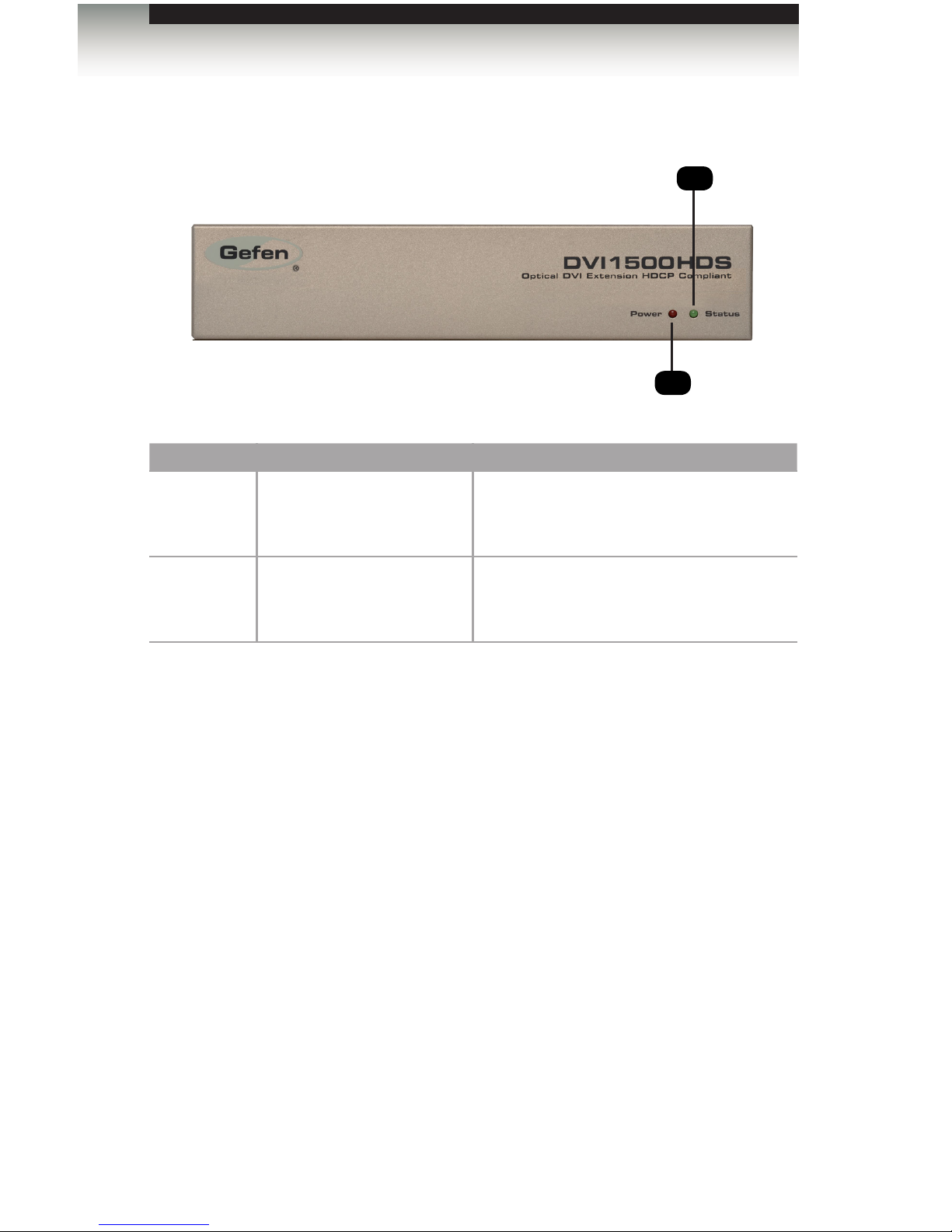
Sender - Front Panel
ID Name Description
1 Power indicator This LED indicator will glow solid red once
the power supply is connected between the
Sender unit and an available electrical outlet.
2 Status indicator This LED will glow bright green to indicate
a solid connection between the Sender unit
and Receiver unit.
Getting Started
Sender Unit
1
2
Page 13

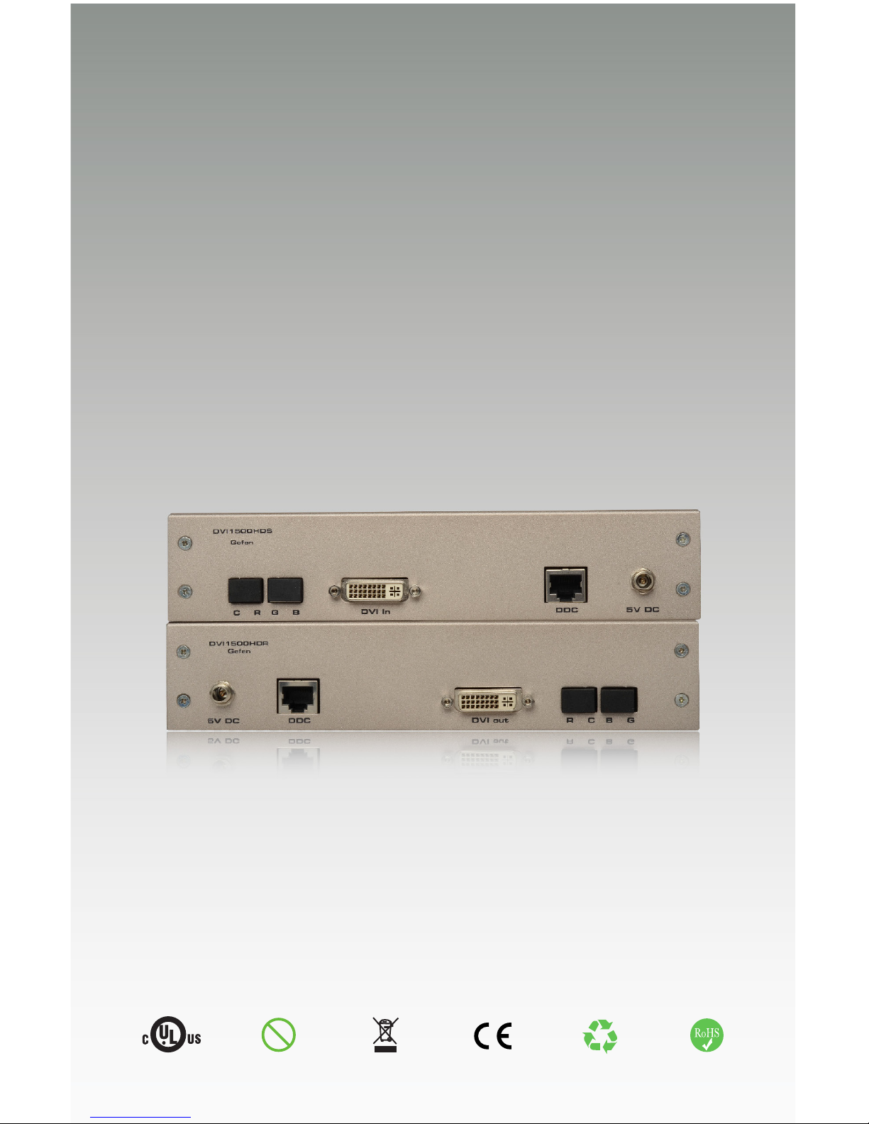
Sender - Back Panel
ID Name Description
1 C R G B Connect four LC-terminated ber optic
cables between each of these ports to the
associated ports on the Receiver unit.
See Connecting the DVI 1500HD for
details on connecting ber optic cables.
2 DVI In Connect the included DVI cable between the
DVI In port and the DVI source.
3 DDC Connect a CAT-5e cable between this port
and the DDC port on the Receiver unit.
This connection is only required when
extending HDCP content.
4 5V DC Connect the included locking 5V DC power
supply from this power receptacle to an
available electrical outlet.
page | 3
Getting Started
Sender Unit
2 3 41
Page 14

page | 4
Receiver - Front Panel
ID Name Description
1 Status indicator This LED will glow bright green to indicate
a solid connection between the Sender unit
and Receiver unit.
2 Power indicator This LED indicator will glow solid red once
the power supply is connected between the
Sender unit and an available electrical outlet.
Getting Started
Receiver Unit
2
1
Page 15
page | 5
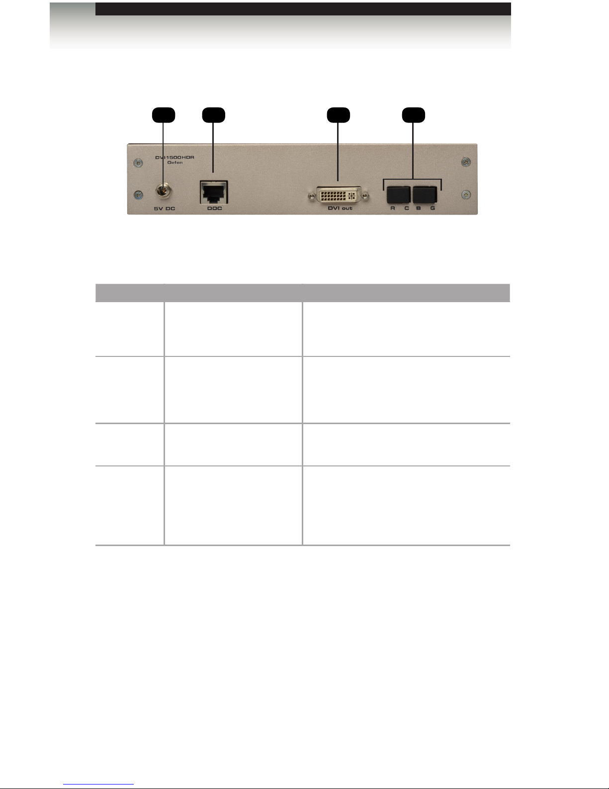
Receiver - Back Panel
ID Name Description
1 5V DC Connect the included locking 5V DC power
supply from this power receptacle to an
available electrical outlet.
2 DDC Connect a CAT-5e cable between this port
and the DDC port on the Sender unit.
This connection is only required when
extending HDCP content.
3 DVI Out Connect a DVI cable between this port and
the display.
4 R C B G Connect four LC-terminated ber optic
cables between each of these ports to the
associated ports on the Sender unit.
See Connecting the DVI 1500HD for
details on connecting ber optic cables.
Getting Started
Receiver Unit
1 32 4
Page 16

page | 6
Page Title
Connecting the DVI 1500HD
1. Connect the included DVI cable from the source to the DVI In port on the Sender unit.
2. Connect a DVI cable from the display to the DVI Out port on the Receiver unit.
3. Connect 4 strands of LC-terminated multimode ber optic cable from the Sender
unit to the Receiver unit. Remove the protective rubber covers to expose each
of the LC ports.
4. OPTIONAL: If HDCP content will be used, connect a CAT-5e cable between the
DDC port on the Sender and Receiver unit.
When extending HDCP content, the maximum extension distance for the ber optic
and CAT-5e cable is 330 feet (100 meters).
5. Connect the included locking 5V DC power supplies to the power receptacles on both
the Sender and Receiver unit. Do not overtighten the locking connectors.
Getting Started
Installation
IMPORTANT: Each ber optic port is identied by the letter R,G,B,
and C. Make sure that the ber optic cables between the Sender
and Receiver unit are connected to the proper port, as shown below.
Page 17

page | 7
Page Title
Sample Wiring Diagram
Getting Started
EXT-DVI-1500HD
Sender
Receiver
Computer
DVI Monitor
DVI CABLE
CAT-5 CABLE
4X FIBER OPTIC LC-LC CABLE
(Up To 330 FT w/HDCP)
(Up To 1,650 FT)
Installation
Page 18

Page 19

DVI 1500HD
02 Appendix
Network Cable Diagram ...................................................................................... 10
Rack Tray Installation ...........................................................................................11
Specications ...................................................................................................... 12
Page 20

page | 10
Front of RJ-45 Connector
Gefen recommends the TIA/EIA-568-B wiring option. Use the table below when
eld-terminating cable for use with Gefen products.
Pin Color Description
1 Orange / White TD+ (Transmit Data, positive differential signal)
2 Orange TD- (Transmit Data, negative differential signal)
3 Green / White RD+ (Receive Data, positive differential signal)
4 Blue Unused
5 Blue / White Unused
6 Green RD- (Receive Data, negative differential signal)
7 Brown / White Unused
8 Brown / White Unused
CAT-5e cabling comes in stranded and solid core types. Gefen recommends using solid
core cabling.
It is recommended to use one continuous run from one end to the other. Patch cable is
not recommended.
1 2 3 4 5 6 7 8
Appendix
Network Cable Diagram
Page 21

page | 11
The following illustrations provide instructions for installing the Sender and/or Receiver
unit(s) in the Gefen 1U Rack Tray (Gefen part no. EXT-RACK-1U).
Appendix
Rack Tray Installation
Step 1 Step 2
Step 3 Step 4
Step 5 Step 6
Turn unit upside down. Remove rubber feet.
Line up holes on unit and rack tray. Install countersink screws .
Ensure the unit is installed securely. Unit has been installed into rack tray.
Page 22

page | 12
Supported Formats
Resolution (max.) • 1920 x 1200
Electrical
Maximum Pixel Clock • 165 MHz
Input Video Signal • 1.2V p-p
Input DDC Signal • 5V p-p (TTL)
Connectors
Video Input • 1 x DVI-D 19-pin, female (digital only)
Video Output • 1 x DVI-D 19-pin, female (digital only)
Fiber Connectors (Sender / Receiver) • 4 x LC-type
DDC Connector • 1 x RJ-45, sheilded
Power Supply • Locking
Operational
Power Input • 1 x 5V DC
Power Consumption • 10W (max.) each
Operating Humidity • 5% to 80%
Storage Humidity • 5% to 90%
Physical
Dimensions (W x H x D) • 6.5” x 1.7” x 4.5”
(165mm x 43mm x 114mm)
Unit Weight (each) • 0.8 lbs (0.37 kg)
Appendix
Specications
Page 23

Page 24
This product uses UL or CE listed power supplies.
20600 Nordhoff St., Chatsworth CA 91311
1-800-545-6900 818-772-9100 fax: 818-772-9120
www.gefen.com support@gefen.com
Stretch it, Switch it, Split it, Control it.
Gefen’s got it. ®
Pb
 Loading...