

Page 1

1080P
Page 2

ASKING FOR ASSISTANC
E
T
t
0
0
0
:
e
:
C
e
0600
1
e
f Gef
C
©
d
A1
echnical Suppor
Telephone (818) 772-910
(800) 545-690
Fax (818) 772-912
echnical Support Hours
:00 AM to 5:00 PM Monday through Friday, Pacifi c Tim
Write To
efen, LL
o Customer Servic
2
Nordhoff St
hatsworth, CA 9131
www.gefenpro.com
upport@gefenpro.com
Notic
efen LLC reserves the right to make changes in the hard ware, packaging and
any accompanying doc u men ta tion without prior written notice.
16x16 3GSDI Push Button Matrix is a trademark o
2011 Gefen LLC. All Rights Reserve
All trademarks are the property of their respective owners.
en LL
ev
Page 3

CONTENT
S
oduction
t
t
x
x
n
n
e
ode Buttons
Sy
e
e
Cy
e
e
n
n
e
g
n
e
e
n
y
g
1 Intr
2 Operation Notes
Features
4 Front Panel Layou
Front Panel Descriptions
Back Panel Layou
7 Back Panel Descriptions
Connecting the 16x16 3GSDI Push Button Matri
Wiring Diagram
Operating the 16x16 3GSDI Push Button Matri
The Standby Scree
Displaying Additional Informatio
10 Displaying the Current Routing Stat
11 M
11 Routing Sources
12
12 Standby Mod
13
14 Saving the current Routing Stat
15 Recalling a stored Routing Stat
16 Masking Outputs
17 Communication Modes
18 IR Remote Control Descriptions
19 IR Remote Control Installatio
20 IR Remote Control Confi guratio
21 Using the IR Remote Control
22 RS-232 Serial Interfac
23 RS-232 Serial Control
23 Reference Signal Commands
24 IP Confi guration Commands
27 General Commands
28 Routing Commands
IP Control
View Matrix Status
1 Maskin
2 IP Confi guratio
3 Backup / Restor
4 Firmware Updat
5 Warning Messages
6 Rack Mount Safety Informatio
7 Specifi cations
8 Warrant
9 Licensin
stem Lock Mod
cling between Information Screens
Page 4

x
y
g
INTRODUCTIO
N
ongratulations on your purchase of the 16x16 3GSDI Push Button Matrix. Your
omplete satisfaction is very important to us.
efen
efen delivers innovative, progressive computer and electronics add-on solutions
that harness integration, extension, distribution and conversion technologies.
efen’s reliable, plug-and-play products supplement cross-platform computer
stems, professional audio/video environments and HDTV systems of all sizes
with hard-working solutions that are easy to implement and simple to operate.
he Gefen 16x16 3GSDI Push Button Matri
Now you can easily combine sixteen cross-platform computers and sixteen
digital displays using the 16x16 3GSDI Push Button Matrix. The Push Button
atrix provides a simple, reliable and highly effective method of routing multiple
omputer workstations. Each 3GSDI source is capable of displaying video on an
one of 16 3GSDI displays. The Push Button Matrix can be controlled by usin
ither the buttons on the front panel, the built-in RS-232 interface, or the included
IR remote.
How It Works
The 16x16 3GSDI Push Button Matrix has sixteen (16) inputs and sixteen (16)
outputs. Connect up to sixteen (16) 3GSDI sources to the 3GSDI input ports.
onnect up to sixteen (16) 3GSDI outputs to the displays. Plug in the power cord
and power on the Push Button Matrix. The connected displays will show video
according to the selection.
Page 5

X
y
OPERATION NOTE
S
:
osed o
.
READ THESE NOTES BEFORE INSTALLING OR
OPERATING THE 16X16 3GSDI PUSH BUTTON MATRI
• There is no internal scaling in the 16x16 3GSDI Push Button Matrix. All of
the attached monitors must be able to displa
ource devices. For maximum compatibility it is recommended that only one
ompatible/common resolution be used by all of the source devices.
•
outing features can be accessed using the serial control interface.
• IP Control will be available in a future fi rmware release.
the resolutions output by the
IMPORTANT
assembly, do not block the ventilation holes of the enclosure
If the unit is installed in a cl
r multi-rack
Page 6

f
y
d
e
n
/Off
h
)
e
x
t
d
FEATURE
S
Features
•
upports resolutions up to 1080p, 1920x1200, and 2K.
• Front panel control buttons
•
erial interface for remote control via a computer or control automation
devices supports RS-232 and RS-485 protocols.
• IP Control
• Discrete IR remote control
•
edundant Internal AC power suppl
•
utput masking comman
•
tandby mod
•
rounding pi
• IR Sensor
• IR Extender
• Power On
•
tatus LCD (shows routing status
•
1) GefenPRO 16x16 3GSDI Push Button Matri
1)IR Remote Control uni
1) AC Power Cor
1) Set of Rack Ears
1) User Manual
k mountabl
ackage Includes
switc
or local switching.
Page 7

FRONT PANEL LAYOU
T
Front Panel
5
Page 8

FRONT PANEL DESCRIPTION
S
s
fo
)
r
y
w
)
Front Panel
Mode Button
These buttons are used to control other features on the product. See pages 11 -
r more information.
17
Output Buttons (1 - 16
sed for routing an Input to an Output. Each of these buttons represents an
utput. See page 11 for more information on routing 3GSDI sources.
Power Indicato
This LED indicator will glow red when the power is turned on.
4 LCD Displa
Displays the current routing status of the Matrix and is also used to manage
ource routing.
5 IR Windo
eceives signals from the IR Remote Control unit.
6 Input Buttons (1 - 16
sed for routing an Input to an Output. Each of these buttons represents an
Input. See page 11 for more information on routing 3GSDI sources.
5
Page 9

BACK PANEL LAYOU
T
Back Panel
7
5
Page 10

BACK PANEL DESCRIPTION
S
l
r
)
g
t
3GS
r
e
s
y)
)
r
Back Pane
eference In Connecto
onnect an external reference to this connector. Bi-level (black burst) and tri-
evel sync are supported.
G-SDI Output Ports (1 - 16
onnect 3G-SDI monitors to these ports.
Grounding Terminal
Provides a discharge path to ground in case a short circuit occurs between the
hot” lead of the power supply and the enclosure of the Matrix. The groundin
wire should be attached from the grounding terminal to an approved ground
ath.
S-232 Serial Por
onnects to the RS-232 control device. The 16x16 3GSDI Matrix may be
witched remotely using this port. See page 29 for more information.
P Control Interface
onnect the 16x16
Fuse Drawe
Each power receptacle houses a fuse drawer. Within each fuse drawer ar
two (2) 250 V fuses. One fuse is active and the other is a spare.
DI Matrix to a network in order to use IP control.
10/220 AC Power Receptacle
onnect one power cord to both power receptacles. The redundant (secondar
ower cable should be connected to an electrical outlet on a different circuit.
G-SDI Input Ports (1 - 16
onnect 3G-SDI source devices to these ports.
eference Loop Connecto
eference Loop connector.
7
Page 11
CONNECTING TH
E
X
x
3GS
x
f
:
x
:
16X16 3GSDI PUSH BUTTON MATRI
How to Connect the 16x16 3GSDI Push Button Matri
1.
onnect up to 16 3G-SDI source devices to the 3G-SDI inputs on the rear
anel of the 16x16 3GSDI Push Button Matrix using SDI cables.
onnect up to 16 3G-SDI displays to the 3G-SDI outputs on the rear panel
2.
of the 16x16
.
onnect the included power cord to the power input receptacle on the rear
anel of the 16x16 3GSDI Push Button Matrix. Connect the opposite end of
the cable into a open wall power socket.
How to Operate the 16x16 3GSDI Push Button Matri
The 16x16 3GSDI Push Button Matrix offers a number of control options. The
ollowing options can be used to control basic routing commands of the 16x16
DI Push Button Matrix
1. Front Panel Control Buttons - Pages 10 - 17.
2. IR Remote Control - Pages 18 - 21.
.
-232 Serial Control - Pages 22 - 29.
4. IP Control - Pages 30 - 33.
DI Push Button Matrix.
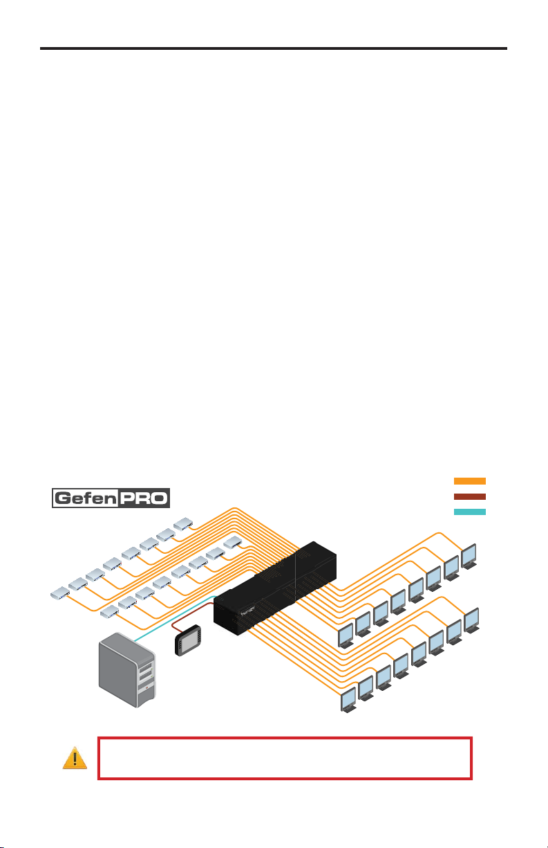
Wiring Diagram for the GefenPRO 16x16 3GSDI Push Button Matri
SDI CABLE
RS-232 CABLE
ETHERNET CABLE
16x
3G-SDI Sources
WARNING
Computer
(IP Control)
This product should always be connected to a
RS-232 Controller
Matrix
16x
3G-SDI Displays
rounded electrical socket.
Page 12
OPERATING TH
E
X
C
f
yed:
boo
oade
:
16X16 3GSDI PUSH BUTTON MATRI
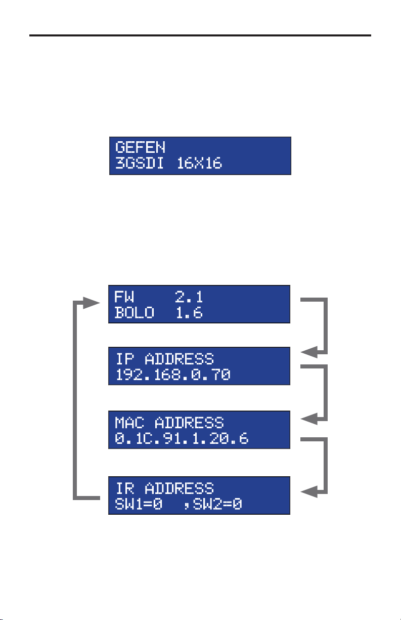
he Standby Screen
The front panel of the 16x16 3GSDI Push Button Matrix has a 16 character 2 line
L
D display. This display will shows the current routing status of the Matrix and
will be used to per
owered on, the Standby Screen will be displa
Pressing the
firmware version and
orm routing commands and other operations. After the unit is
isplaying Additional Information
ancel button, consecutively, will cycle through other screens such
t l
r version
Page 13

OPERATING TH
E
X
e
O
g
:
16X16 3GSDI PUSH BUTTON MATRI
isplaying the Current Routing Stat
1. To display the current routing status of the Matrix, press any one of the Input
or
utput buttons on the front panel.
Input buttons
utput buttons
2. The current routin
blue buttons on the front panel
In the example above, Input 8 (bottom row) is routed to Output 5, Output 7,
and Output 12 (top row). Note that a source does not need to be connected
to the Matrix to display a routing state since all Inputs are routed by default
to their respective outputs (e.g. 1 - 1, 2 - 2, 3 - 3, etc).
state of any output or input will be indicated by glowing
10
Page 14

1
ODE BUTTON
S
g
O
n
Routing Sources
To change the current routing state, press Set Button to activate Routin
.
Press the Set butto
2 Press the desired
lected.
Press any Input on the bottom row of buttons (1 - 16), corresponding to the
ource to be displayed on the output(s).
4 Press the Set button to complete the operation. The system will remain in
outing Mode.
utput button. One or more Output buttons may be
Input buttons
utput buttons
1
Page 15

ODE BUTTON
S
e
f
g
e
ess
on
n
System Lock Mod
Locking the Matrix prevents changes to any of the Matrix settings. This feature
is use
ul in case any of the front panel buttons are pressed by accident. Lockin
the Matrix also prevents changes using the IR Remote Control Unit.
1 Press the Lock button to activate System Lock Mode.
Pr
the Lock butt
2 Press the Lock button a second time to deactivate System Lock Mode.
Standby Mod
1 Press the Cancel button, while in any mode, to return to the Standby Mode
.
ancel butto
Press and hold the Cancel button for 5 seconds to enable or disable Standby
.
12
Page 16

3
ODE BUTTON
S
l
l
cel
n
Cycling between Information Screens
Press the Cancel button, while in Status Check Mode, to cycle through the
Information Screens.
Press the Cancel butto
ance
ance
n
1
Page 17

4
ODE BUTTON
S
e
o
ese
ode
(
n
t
ce
Saving the current Routing Stat
1
et the routing state (see page 11), then press the PreSet button
tivate Pr
t M
.
wice t
Press PreSet button
2 Press an Input button
1 - 16) to store the current routing state.
elect the Inpu
Press the Set button to complete the operation. The system will remain in
ave Current Preset Mode.
Press the Set butto
wi
1
Page 18

ODE BUTTON
S
e
eca
ese
ode
(
n
t
ce
Recalling a stored Routing Stat
Press the PreSet button
2 Press the Input button
to activate R
ll Pr
t M
.
Press PreSet button
1 - 16) of the routing state to be recalled.
elect the Inpu
wi
Press the Set button to complete the operation. The system will remain in
ecall Saved Set Mode.
Press the Set butto
15
Page 19

6
ODE BUTTON
S
ess
ode
t
ess
on
n
asking Outputs
asking prevents the output device (display, etc) from receiving an output signal,
instead of powering-down the output device. The masking process is identical for
asking or unmasking outputs.
1Pr
2
the Mask button to activate Mask M
elect the Output to be masked.
.
Pr
the Mask butt
elect the Outpu
Press the Set button to complete the operation.
1
Press the Set butto
Page 20

ODE BUTTON
S
C
:
n
mmmmm
Communication Modes
The Comm button allows the Matrix to switch between RS-232 and RS-485 (EIA-
485) modes.
1 Press the
omm button to activate the Communications Mode. The current
ommunication method (RS232) will be displayed. Press the Comm button
to cycle through Termination ON and Termination OFF states for RS485
Press the Comm butto
m
17
Page 21

8
IR REMOTE CONTROL DESCRIPTION
S
t
r
ese buttons are used to selec
source is routed to a mo
y
e
RMT-16416IR
Remote Control Uni
Activity Indicato
This LED will be glow yellow each time a button is pressed.
Display and Source Selection Buttons (1 - 16)
Th
NOTE: An Activit
any one of the sixteen buttons indicates a low battery. Replac
the IR Remote Control battery as soon as possible.
t which
Indictor that fl ashes quickly while holding down
nitor.
1
Page 22

y
y
IR REMOTE CONTROL INSTALLATIO
N
t
:
Installing the RMT-16416IR Batter
emove the battery cover on the back of the IR Remote Control unit.
2. Insert the included batter
the battery should be facing up.
.
eplace the battery cover.
The Remote Control unit ships with two batteries. One battery is required for
operation and the other battery is a spare.
WARNING
type. Dispose of used batteries according to the instructions.
Risk of explosion if battery is replaced by an incorrect
into the open battery slot. The positive (+) side of
Battery Slo
19
Page 23

IR REMOTE CONTROL CONFIGURATIO
N
2
2
2
:
0:
efault
:
3:
f
y
y
C
How to Resolve IR Code Confl icts
In the event that IR commands from other remote controls interfere with the
upplied IR Remote Control unit, changing the IR channel on the IR Remote
ontrol unit will fi x the problem. The IR Remote Control unit has a bank of DIP
witches used for setting the IR channel.
The DIP switch bank is located underneath the battery cover.
emote Channel
D
emote Channel 2
eft: Picture o
1
the opened rear batter
emote Channel 1
1
emote Channel
1
ompartment of the IR remote showing the
xposed DIP Switch bank between the batter
hambers.
It is important that the IR channel on the Remote
ontrol unit, matches the IR
hannel set on the 16x16 3GSDI Push Button Matrix. For example, if both
DIP switches on the IR Remote Control unit are set to IR channel 0 (both DIP
witches down), then the 16x16 3GSDI Matrix must also be set to IR channel 0.
ee page 28 on how to change the IR channel on the 16x16 3GSDI Push Button
trix.
0
Page 24

SING THE IR REMOTE CONTROL
g
e
111
313
414
616
t
p
y)
IR Remote Control Key Mappin
Each input and output on the 16x16 3GSDI Push Button Matrix is represented by a
button on the IR Remote Control unit. The table below lists the corresponding inputs
and outputs.
Remote Button
55
77
10 10
1
12 12
1
1
15 15
1
Routing Sources using the IR Remote Control uni
Issuing a routing command is a two step process. The fi rst step is to select the
onitor where the source will be routed. The second step is to select the source.
onitor / Sourc
oute the source device connected to In 12 to the monitor connected to Out 9.
1. Press button 9 (monitor 9) on the IR remote control unit.
2. Press button 12 (source 12) on the IR remote control unit.
The source connected to In 12 will be routed to the 3GSDI destination (displa
onnected to Out 9.
Page 25

p
features are:
?
y
p
?
pg
8
e
1
e
RS-232 SERIAL INTERFAC
E
The 16x16 3GSDI Push Button Matrix can accept commands through the RS-232
erial communications port located on the rear panel. The current RS-232 control
•
witching/routing of inputs to outputs without the RMT-16416IR remote
ntrol.
How do I use these features
These features were initially intended for utilization by custom installers in
automated setups. However, these features can be tested and used by using an
Windows-based PC with a terminal program.
atrix
nly pins 2 (Receive), 3 (Transmit), and 5 (Ground) are used for communication.
A null-modem adapter should not be used with this product.
54321
9876
Only Pins 2 (RX), 3 (TX), and 5 (Ground) are used on the RS-232 serial interface
Bits per second ............................................................................................ 19200
Data bits ...............................................................................................................
Parity ............................................................................................................. Non
top bits ................................................................................................................
Flow Control .................................................................................................. Non
12345
6789
2
Page 26

RS-232 SERIAL CONTROL
/
y
y
:
#C
)
:
#C
y
y
#
e
y
F
s
e
RS-232 Features
-232 remote commands are used to control this product’s features. Features
include input
are available onl
The syntax for each command is always the same
ommand name → Space ( _ ) as command name end fl ag → Parameter 1 →
pace → Parameter 2 → Parameter n → Carriage Return ( \r
ample
ommandName_param1_param2_param3_param4...\r
ntax is NOT case sensitive.
output routing and reference signal commands . These features
through the use of the serial port.
Reference Signal Commands
Command
HECKREF Displa
PRREFTABLE Displa
CHECKREF Command
The #CHECKREF command detects the Ref In signal and displays the data ac-
ording to the Ref tabl
CHECKRE
rameter
Non
escription
the Ref In signal
the table data
Page 27

RS-232 SERIAL CONTROL
#
y
E
s
e
y
n
k
Y
y
t
#
y
D
s
e
PRREFTABLE Command
The #PRREFTABLE command displays the Ref In data table (timings) which are
ecognized by the 16x16 3GSDI Push Button Matrix.
PRREFTABL
rameter
Non
IP Confi guration Commands
Command
PRWEBADD Displa
RSTIP
IPADD
NETMASK
ATEWA
PORT
PRWEBADD Command
Prints the current IP confi guration on the screen.
PRWEBAD
rameter
Non
escription
s the current IP confi guratio
ets IP confi guration to factory settings
ets the IP Address
ets the Net Mas
ets the Gatewa
ets the Por
Page 28

RS-232 SERIAL CONTROL
#
)
y
P
s
eNotes
#
y
s
p
1
p
p
3
IP address [0 - 255]
p
es
RSTIP Command
The #RSTIP command sets the current IP confi guration to factory (default
ettings.
RSTI
rameter
Non
A reboot is required after using this command.
SIPADD Command
The #SIPADD command specifi es a new IP address.
SIPADD param1 param2 param3 param4
rameter
aram
IP address [0 - 255]
aram2 IP address [0 - 255]
aram
aram4 IP address [0 - 255]
Not
A reboot is required after using this command.
5
Page 29

RS-232 SERIAL CONTROL
#
y
s
p
1
p
p
3
IP address [0 - 255]
p
es
#
y
s
p
1
G
p
2
Gateway address [0 - 255]
p
3
Gateway address [0 - 255]
p
G
es
SNETMASK Command
The #SNETMASK command specifi es a new net mask.
SNETMASK param1 param2 param3 param4
rameter
aram
IP address [0 - 255]
aram2 IP address [0 - 255]
aram
aram4 IP address [0 - 255]
Not
A reboot is required after using this command.
SGATEWAY Command
pecifi es the new IP gateway.
SGATEWAY param1 param2 param3 param4
rameter
aram
aram
aram
aram4
Not
A reboot is required after using this command.
ateway address [0 - 255]
ateway address [0 - 255]
Page 30

RS-232 SERIAL CONTROL
#
y
1
s
p
1
es
O
boo
oade
#
.
y
s
e
es
SPORT Command
pecifi es a new port.
SPORT param
rameter
aram
Port [0 - 255]
Not
A reboot is required after using this command.
eneral Commands
Command
ACTIVEBOL
FADEFAULT
RMTIRADD
ACTIVEBOLO Command
The #ACTIVEBOLO command enables the boot loader
ACTIVEBOLO
rameter
Non
Not
This command must be typed twice in order to activate the boot loader.
escription
Enables the
ets all routing states to default settings
et the remote IR channel
t l
r
7
Page 31

RS-232 SERIAL CONTROL
#
y
T
s
e
#
y
1
s
p
x
d
y
m
s
e
FADEFAULT Command
The #FADEFAULT command sets all routing states to default (1 - 1, 2 - 2, 3 - 3,
tc).
FADEFAUL
rameter
Non
RMTIRADD Command
The #RMTIRADD command sets the remote IR channel.
RMTIRADD param
rameter
aram1 IR channel [0 - 3]
Routing Commands
Command
Command
The M command displays the current routing status of the matrix.
rameter
Non
escription
eturns the current routing status of matri
outing comman
outes a single input to all outputs
Page 32

y
2
s
p
p
y
1
s
p
es
p
1
ode
RS-232 SERIAL CONTROL
R Command
The R command allows specifi c routing of inputs and outputs.
param1 param
rameter
aram1
aram2
S Command
The S command routes a single input to all 16 3GSDI outputs.
param
rameter
aram1 Input [1 - 16]
DI Ouput [1 - 16]
DI Input
1 - 16]
Not
etting
aram
to a value of 0 will place the matrix in
eans that Input1 will be routed to Output1, Input2 will be routed to Output2, and
on.
ne-to-one m
This
9
Page 33

IP CONTROL
(
V
page
V
e
y
:
g
The GefenPRO 16x16 3GSDI Push Button Matrix supports IP-based control
sing an integrated Web interface. To access this feature, an IP address, subnet,
ateway, and port number need to be set on the 16x16 3GSDI Push Button
atrix
efault IP: 192.168.0.70 Subnet: 255.255.255.0 Gateway: 192.168.0.1
ort: 80
ettings for this product to properly communicate on the network.
The IP control setting can be confi gured via the RS-232 control interface. Once
this has been accomplished, access to the Web Interface is possible. Simply type
the IP address that was assigned to the product in a web browser to access the
iew Matrix Status
Th
. Consult the network administrator to obtain the proper IP address and
.
iew Matrix Status
ain Page will displa
tes.
the current status and can also be used to create
To create a new route, follow the steps below
1.
elect which outputs will display the source by clicking on each check box.
2.
elect the radio button of the input that will be routed to each output.
.
lick the SWITCH button to update the new routing confi guration.
This pa
Refresh” button can be pressed to refresh the status of the Matrix.
e will automatically refresh every minute. However, at anytime the
0
Page 34

IP CONTROL
g
e
g
ge
:
askin
Th
askin
this page, all outputs can be set to “Active” or “Mask”. When an output is set to
Active”, it will command normally. When an output is set to “Mask”, it will not
output any video. To set the “Active” or “Mask” mode, follow the steps below.
age is used to hide an output from displaying any video. From
1.
elect either “Active” or “Mask” for any number of desired outputs.
2. Press the “Submit” button to initiate the change(s).
After this command is complete the user will be returned to the
This page will automatically refresh every minute, however, at anytime the
Refresh” button can be pressed to refresh the status of the matrix.
NOTE
All masked outputs will become active if the unit is power-cycled.
ain Pa
Page 35

Th
e
f
(Def
)
)
)
)
f
V
IP Confi guration
access the Web inter
IP CONTROL
IP Confi guration
age is used to set the IP settings that will be used to
ace. The following items can be confi gured from this menu.
• IP Address
•
ubnet (Default: 255.255.255.0
•
ateway (192.168.0.1
• Port (Default: 80
•
ault: 192.168.0.70
To change these settings follow the steps below.
1. Enter the desired network information into the fi elds provided.
2. Press the “Save” button to initiate the change(s).
Note: A
At anytime, the “Reset” button can be pressed to return the IP settings to their
ter this command is complete the user will be returned to the
atrix Status
nit is restarted. Disconnect the power from the unit and reconnect power for
hanges to take effect.
lts.
age. Settings made on this page will not take effect until the
iew
2
Page 36

e
Th
e
f
Backup/Restore
IP CONTROL
Backup / Restor
age is used to backup and restore setup confi gurations.
Note: This
eature will be implemented in a future release.
Page 37

FIRMWARE UPDAT
E
e
:
ce
:
fi
_
)
ode
f
o
e
g
:
y!
Firmware Updat
Follow the on-screen instructions to complete the fi rmware update process
1.
sing Hyperterminal, enter the #ACTIVEBOLO command
2. Press [1] on the computer keyboard to begin downloading program to the
temporary memory.
. A message will appear in Hyperterminal
aiting for the fi le to be sent ... (press ‘a’ to abort)
wi
4. In Hyperterminal, click
.
lick Browse... and select the .BIN
IP_2_1.bin
.
elect Ym
7.
lick
. After a few moments, a message will appear in Hyperterminal
rogramming Completed Successfull
m
n th
ransfer > Send File...
or the protocol.
end File dialo
le to be uploaded (e.g. 3GSDI16X16
box.
Page 38

WARNING MESSAGE
S
e
y
y:
3GS
y:
!!!
e
System Failur
In the case of a critical malcommand, the following warning message will be
displa
ed on the Main Displa
If the16x16
rogram, the following message will appear on the displa
ystem failure
Power-down the Matrix immediately and contact Gefen Technical Support. See
Asking for Assistanc
DI Push Button Matrix is connected to a PC using a terminal
at the beginning of this manual.
5
Page 39

RACK MOUNT SAFETY INFORMATIO
N
ease
eeded to ma
ecommended
.
aximum recommended ambient temperature: 45 ˚C (104 ˚F).
. Incr
temperature inside the rack.
. Do not exceed maximum weight loads for the rack. Install heavier
.
the air fl ow as n
quipment in the lower part of the rack to maintain stability.
onnect a bonding wire between an approved safety ground and the
rounding screw on the chassis.
intain the r
Page 40

SPECIFICATION
S
)
)
)
K
C
Ω
(Sync)
e
y)
)
d
Input / Output
•
DI (SMPTE 259MI up to 360 Mbps
•
D-SDI (SMPTE 292M up to 1.485 Gbps
•
-SDI (SMPTE 424M/425M up to 3.0 Gbps
upported Formats......................................................All SD, HD, and 3G formats
aximum Resolution...........................................................1080p, 1920x1200, 2
Input / Output Connector-type..........................................................................BN
Input / Output Impedance.................................................................................75
eference
-232 Interface.................................................................................DB-9, femal
Power Supply..................................................100 ~ 240 V AC (x2 for redundanc
Power Consumption........................................................................................30 W
Operating Temperature...............................................0 ˚C ~ 45 ˚C / 32 ˚F ~ 104 ˚F
torage Temperature...............................................-20 ˚C ~ 60 ˚C / -4 ˚F ~ 140 ˚F
elative Humidity...............................................20% ~ 90% RH (no condensation
ack mountable................................................ 2U rack space, rack ears include
Dimensions............................................................................. 19” W x 2U H x 7” D
hipping Weight........................................................................................... 29 lbs.
............................................................NTSC, PAL, and Tri-Level
7
Page 41

efen warrants the equipment it manufactures to be free from defects in material
f
N
.
and workmanship.
I
equipment fails because of such defects and Gefen is notifi ed within two (2)
ears from the date of shipment, Gefen will, at its option, repair or replace the
quipment, provided that the equipment has not been subjected to mechanical,
lectrical, or other abuse or modifi cations. Equipment that fails under conditions
other than those covered will be repaired at the current price of parts and labor in
ect at the time of repair. Such repairs are warranted for ninety (90) days from
the day of reshipment to the Buyer.
This warranty is in lieu of all other warranties expressed or implied, including
without limitation, any implied warranty or merchantability or fi tness for any
articular purpose, all of which are expressly disclaimed.
1. Proof of sale may be required in order to claim warranty.
2.
ustomers outside the US are responsible for shipping charges to and from
efen.
.
opper cables are limited to a 30 day warranty and cables must be in their
original condition.
The information in this manual has been carefully checked and is believed to
be accurate. However, Gefen assumes no responsibility for any inaccuracies
that may be contained in this manual. In no event will Gefen be liable for
direct, indirect, special, incidental, or consequential damages resulting from
any defect or omission in this manual, even if advised of the possibility of such
damages. The technical information contained herein regarding the features and
pecifi cations is subject to change without notice.
For the latest warranty coverage information, refer to the Warranty and Return
Policy under the Support section of the Gefen Web site at www.gefen.com.
RODUCT REGISTRATIO
lease register your product online by visiting the Register Product page
nder the Support section of the Gefen Web site
Page 42

ICENSIN
G
:
:
/
,
GOODS OR S
OSS O
)
N
OSS
SUC
wIP is licenced under the BSD licence
opyright (c) 2001-2004 Swedish Institute of Computer Science.
All rights reserved.
edistribution and use in source and binary forms, with or without modifi cation,
are permitted provided that the following conditions are met
1.
edistributions of source code must retain the above copyright notice, this
ist of conditions and the following disclaimer.
2.
edistributions in binary form must reproduce the above copyright notice,
this list of conditions and the following disclaimer in the documentation and
or other materials provided with the distribution.
. The name of the author may not be used to endorse or promote products
derived from this software without specifi c prior written permission.
THIS SOFTWARE IS PROVIDED BY THE AUTHOR ``AS IS’’ AND ANY
EXPRESS OR IMPLIED WARRANTIES, INCLUDING, BUT NOT LIMITED TO,
THE IMPLIED WARRANTIES OF MERCHANTABILITY AND FITNESS FOR
A PART ICULAR PURPOSE ARE DISCLAIMED. IN NO EVENT SHALL THE
AUTHOR BE LIABLE FOR ANY DIRECT, INDIRECT, INCIDENTAL, SPECIAL
EXEMPLARY, OR CONSEQUENTIAL DAMAGES (INCLUDING, BUT NOT
LIMITED TO, PROCUREMENT OF SUBSTITUTE
L
EVEN IF ADVISED OF THE P
F USE, DATA, OR PROFITS; OR BUSINESS INTERRUPTION
WEVER CAUSED AND ON ANY THEORY OF LIABILITY, WHETHER I
NTRACT, STRICT LIABILITY, OR TORT (INCLUDING NEGLIGENCE OR
THERWISE) ARISING IN ANY WAY OUT OF THE USE OF THIS SOFTWARE,
IBILITY OF
H DAMAGE.
ERVICES;
9
Page 43

v
A1
Pb
 Loading...