

Page 1

6” QuickPanel View
IC754VSI06STD
IC754VBI06STD
IC754VSI06MTD
IC754VBI06MTD
Hardware User’s Guide
May 2004
GFK-2325
Page 2

Page 3

All rights reserved. No part of this publication may be reproduced in any form or by
any electronic or mechanical means, including photocopying and recording,
without permission in writing from GE Fanuc Automation Americas, Inc.
Disclaimer of Warranties and Liability
The information contained in this manual is believed to be accurate and reliable.
However, GE Fanuc Automation Americas, Inc. assumes no responsibilities for any
errors, omissions or inaccuracies whatsoever. Without limiting the forgoing, GE
Fanuc Automation Americas, Inc. disclaims any and all warranties, expressed or
implied, including the warranty of merchantability and fitness for a particular
purpose, with respect to the information contained in this manual and the
equipment or software described herein. The entire risk as to the quality and
performance of such information, equipment and software, is upon the buyer or
user. GE Fanuc Automation Americas, Inc. shall not be liable for any damages,
including special or consequential damages, arising out of the use of such
information, equipment and software, even if GE Fanuc Automation Americas, Inc.
has been advised in advance of the possibility of such damages. The use of the
information contained in the manual and the software described herein is subject to
GE Fanuc Automation America’s standard license agreement, which must be
executed by the buyer or user before the use of such information, equipment or
software.
Notice
GE Fanuc Automation Americas, Inc. reserves the right to make improvements to the
products described in this publication at any time and without notice.
© 2004 GE Fanuc Automation Americas, Inc. All rights reserved. QuickPanel View is
a trademark of GE Fanuc Automation Americas, Inc. Any other trademarks
referenced herein are the property of their respective owners and used solely for
purposes of identifying compatibility with the products of GE Fanuc Automation
Americas, Inc.
The 6” QuickPanel View has been tested and found to meet or exceed the
requirements of U.S. (47 CFR 15), Canadian (ICES-003), Australian (AS/NZS 3548)
and European (EN55022) regulations for Class A digital devices when installed in
accordance with guidelines noted in this manual.
The FCC requires the following note to be published according to FCC guidelines:
This equipment generates, uses and can radiate radio
frequency energy and, if not installed in accordance with this
instruction manual, may cause harmful interference to radio
communications. It has been tested and found to comply with
the limits of a Class A digital device pursuant to Part 15 of the
FCC rules, which are designed to provide reasonable
protection against harmful interference when operated in a
commercial environment. Operation of this equipment in a
residential area is likely to cause harmful interference, in which
case users will be required to correct the interference at their
own expense.
Page 4

Industry Canada requires the following note to be published:
This Class A digital apparatus complies with Canadian ICES-
003.
The following statements are required to appear for Class I Div 2 Hazardous
Locations.
1. EQUIPMENT LABELED WITH REFERENCE TO CLASS 1, DIVISION 2, GROUPS
A, B, C AND D, HAZARDOUS LOCATIONS IS SUITABLE FOR USE IN CLASS 1,
DIVISION 2, GROUPS A, B, C AND D, OR NON-HAZARDOUS LOCATIONS
ONLY.
2. WARNING - EXPLOSION HAZARD -SUBSTITUTION OF COMPONENTS MAY
IMPAIR SUITABILITY FOR CLASS I, DIVISION 2.
3. WARNING - EXPLOSION HAZARD - DO NOT CONNECT OR DISCONNECT
EQUIPMENT UNLESS POWER HAS BEEN SWITCHED OFF OR AREA IS KNOWN
TO BE NON-HARZARDOUS.
For a complete list of agency qualifications, please refer to appendix A1.
We want to hear from you. If you have any comments, questions, or suggestions
about our documentation, send them to the following email address:
doc@gefanuc.com.
Page 5

Contents
1 Welcome 1
Getting Started . . . . . . . . . . . . . . . . . . . . . . . . . . . . . . . . . . . . . . . .2
Basic Setup . . . . . . . . . . . . . . . . . . . . . . . . . . . . . . . . . . . . . . . .2
QuickPanel View Unit Runtime Setup . . . . . . . . . . . . . . . . . . . .3
Startup . . . . . . . . . . . . . . . . . . . . . . . . . . . . . . . . . . . . . . . . . . . .3
Shutdown . . . . . . . . . . . . . . . . . . . . . . . . . . . . . . . . . . . . . . . . .4
Panel Cutout . . . . . . . . . . . . . . . . . . . . . . . . . . . . . . . . . . . . . . .4
Technical Support . . . . . . . . . . . . . . . . . . . . . . . . . . . . . . . . . . . . . .6
2 Overview 7
QuickPanel View Hardware . . . . . . . . . . . . . . . . . . . . . . . . . . . . . .8
Layout Diagram . . . . . . . . . . . . . . . . . . . . . . . . . . . . . . . . . . . . .8
Block Diagram . . . . . . . . . . . . . . . . . . . . . . . . . . . . . . . . . . . . .9
QuickPanel View Software . . . . . . . . . . . . . . . . . . . . . . . . . . . . . .10
Windows CE.NET . . . . . . . . . . . . . . . . . . . . . . . . . . . . . . . . . .10
Working with Windows CE . . . . . . . . . . . . . . . . . . . . . . . . . . .10
Pocket Internet Explorer . . . . . . . . . . . . . . . . . . . . . . . . . . . . . .11
Backup . . . . . . . . . . . . . . . . . . . . . . . . . . . . . . . . . . . . . . . . . .13
Storage Manager . . . . . . . . . . . . . . . . . . . . . . . . . . . . . . . . . . .14
System Information . . . . . . . . . . . . . . . . . . . . . . . . . . . . . . . . .14
Copy Project to Flash Card . . . . . . . . . . . . . . . . . . . . . . . . . . .15
Emulate PPC . . . . . . . . . . . . . . . . . . . . . . . . . . . . . . . . . . . . . .15
HTTP File Transfer Utility . . . . . . . . . . . . . . . . . . . . . . . . . . . .16
3 Detailed Operation 19
GFK-2325 6" QuickPanel View v
Touch Screen Display . . . . . . . . . . . . . . . . . . . . . . . . . . . . . . . . . .20
Touch Screen . . . . . . . . . . . . . . . . . . . . . . . . . . . . . . . . . . . . .22
Keyboard . . . . . . . . . . . . . . . . . . . . . . . . . . . . . . . . . . . . . . . . . . .25
Soft Input Panel . . . . . . . . . . . . . . . . . . . . . . . . . . . . . . . . . . . .25
Communication Port . . . . . . . . . . . . . . . . . . . . . . . . . . . . . . . . . . .29
COM1- Serial . . . . . . . . . . . . . . . . . . . . . . . . . . . . . . . . . . . . .29
Working with the COM port . . . . . . . . . . . . . . . . . . . . . . . . . .30
CF Port . . . . . . . . . . . . . . . . . . . . . . . . . . . . . . . . . . . . . . . . . . . . .34
Ethernet . . . . . . . . . . . . . . . . . . . . . . . . . . . . . . . . . . . . . . . . . . . .35
Expansion Bus . . . . . . . . . . . . . . . . . . . . . . . . . . . . . . . . . . . . . . . .39
Page 6

Contents
DIP Switches . . . . . . . . . . . . . . . . . . . . . . . . . . . . . . . . . . . . . . . . 40
Memory . . . . . . . . . . . . . . . . . . . . . . . . . . . . . . . . . . . . . . . . . . . . 42
Flash Memory . . . . . . . . . . . . . . . . . . . . . . . . . . . . . . . . . . . . . 42
SRAM Memory . . . . . . . . . . . . . . . . . . . . . . . . . . . . . . . . . . . . 43
DRAM Memory . . . . . . . . . . . . . . . . . . . . . . . . . . . . . . . . . . . 43
Boot Loader ROM . . . . . . . . . . . . . . . . . . . . . . . . . . . . . . . . . 44
Memory Expansion Slot . . . . . . . . . . . . . . . . . . . . . . . . . . . . . 44
Other Subsystems . . . . . . . . . . . . . . . . . . . . . . . . . . . . . . . . . . . . . 45
Power Management . . . . . . . . . . . . . . . . . . . . . . . . . . . . . . . . 45
Battery Backup . . . . . . . . . . . . . . . . . . . . . . . . . . . . . . . . . . . . 45
Real-time Clock . . . . . . . . . . . . . . . . . . . . . . . . . . . . . . . . . . . 46
A1 Design Specifications 49
Physical . . . . . . . . . . . . . . . . . . . . . . . . . . . . . . . . . . . . . . . . . 49
DC Power . . . . . . . . . . . . . . . . . . . . . . . . . . . . . . . . . . . . . . . . 49
Display . . . . . . . . . . . . . . . . . . . . . . . . . . . . . . . . . . . . . . . . . 50
Front Panel . . . . . . . . . . . . . . . . . . . . . . . . . . . . . . . . . . . . . . . 50
Touch Screen . . . . . . . . . . . . . . . . . . . . . . . . . . . . . . . . . . . . . 50
CPU . . . . . . . . . . . . . . . . . . . . . . . . . . . . . . . . . . . . . . . . . . . . 50
Memory . . . . . . . . . . . . . . . . . . . . . . . . . . . . . . . . . . . . . . . . . 51
Memory Expansion Slot . . . . . . . . . . . . . . . . . . . . . . . . . . . . . 51
Expansion Ports . . . . . . . . . . . . . . . . . . . . . . . . . . . . . . . . . . . 51
Communication Port . . . . . . . . . . . . . . . . . . . . . . . . . . . . . . . . 52
Environmental . . . . . . . . . . . . . . . . . . . . . . . . . . . . . . . . . . . . 52
Battery . . . . . . . . . . . . . . . . . . . . . . . . . . . . . . . . . . . . . . . . . . 52
Calendar/Clock . . . . . . . . . . . . . . . . . . . . . . . . . . . . . . . . . . . . 53
Agency Qualifications . . . . . . . . . . . . . . . . . . . . . . . . . . . . . . 53
A2 Troubleshooting 55
Index 57
vi 6" QuickPanel View GFK-2325
Power up . . . . . . . . . . . . . . . . . . . . . . . . . . . . . . . . . . . . . . . . 55
Pocket Internet Explorer . . . . . . . . . . . . . . . . . . . . . . . . . . . . . 55
Page 7

1
Welcome
Congratulations on your purchase of a QuickPanel View, the most advanced
compact HMI computer available. The QuickPanel View is available in different
configurations to suit your requirements. Equally at home in a networked
environment or as a stand-alone unit, the QuickPanel View is the ideal solution for
factory floor HMI.
Powered by Microsoft Windows CE.NET
choice, the QuickPanel View provides a fast track for application program
development. The commonality with other versions of Windows simplifies porting
your existing program code. Another benefit of Windows CE is the familiarity of
the user interface, shortening the learning curve for operators and developers alike.
The availability of third-party application software makes this operating system
even more attractive.
The 6" QuickPanel View is an all-in-one microcomputer designed for maximum
flexibility. The design, based on an advanced Intel
together a high-resolution operator interface with a variety of I/O options. With
many standard ports and expansion busses from which to choose, you can connect
to most industrial equipment.
TM
, today’s embedded operating system of
®
microprocessor, brings
The QuickPanel View is equipped with several memory types to satisfy even the
most demanding applications. A 32 MB section of DRAM is split between the
operating system, an object store, and application memory. A 32 MB section of
non-volatile FLASH memory, functioning as a virtual hard drive, is divided
between the operating system and persistent storage for application programs. The
retentive memory consists of 512 KB of battery-backed SRAM for data storage,
ensuring your valuable data will never be lost, even during a power failure.
The many features of the QuickPanel View make it an obvious choice for a world
of applications. Your smart choice will provide reliable operation for years to
come.
GFK-2325 6" QuickPanel View 1
Page 8

Welcome
1
Getting Started
GETTING STARTED
Basic Setup
Your 6" QuickPanel View is shipped ready for use after a few configuration steps.
To power up all you need to do is connect a DC power supply via the supplied
quick-connect plug. Depending on your application, you may also want to
connect and configure optional input devices (see page 25), communications ports
(see page 29) and expansion adapters (see page 39).
To connect a DC power supply
1. Using the three screw terminals shown in the following diagram, attach a 24VDC, 24W power supply to the plug
2. Insert the plug into the power supply socket and securely tighten the attaching screws.
Optional Ethernet Connection
Caution -
equipment, ensure that the DC supply is disconnected from power and that the
leads are not energized before attaching them to the unit's power supply plug.
supplied with the QuickPanel View. See the DC Power section starting on page 49 for power supply and conductor
specifications.
Bottom
Electrical Shock Hazard: To avoid personal injury or damage to
Optional Expansion I/O
Power Supply
Power Supply Plug
2 6" QuickPanel View GFK-2325
Power Supply Socket
+ 24 VDC
0V
Frame Ground
Insert leads in screw end
Page 9

To start the QuickPanel View
1. Apply AC power to the 24VDC supply.
Welcome
Getting Started
QuickPanel View Unit Runtime Setup
To download an application to a QuickPanel View, you must set up a data link
between it and your development workstation. For more information, see
“Ethernet” (page 35) and look up “Downloading a Machine Edition Project” in the
Machine Edition online help.
Startup
When you first start up the QuickPanel View, a few configuration steps are
necessary.
Once power is applied, the QuickPanel View begins initializing. The first thing to
appear on the display is the splash screen.
2. To skip running any programs included in the StartUp folder, tap Don’t run StartUp programs.
The splash screen disappears automatically after about 5 seconds. The Windows
CE desktop then becomes visible.
3. Tap Start, point to Settings, then tap Control Panel.
4. In the Control Panel, double-tap Display to configure the LCD display (see page 20).
5. In the Control Panel, double-tap Stylus to configure the touch screen (see page 22).
6. In the Control Panel, double-tap Date and Time to configure the system clock (see page 46).
7. In the Control Panel, double-tap Network and Dial-up Connections to configure network settings (see
page 36).
8. On the desktop, double-tap Backup to save any new settings through a power cycle (see page 13).
GFK-2325 6" QuickPanel View 3
Page 10
Welcome
1
Getting Started
Shutdown
There are no specific dangers associated with a power failure or other unplanned
shutdown of the QuickPanel View. In general, programs are retained in FLASH
memory and user data can be retained in battery-backed SRAM. Some operating
system settings are kept only with user intervention, so in order to carry out a
graceful shutdown of the QuickPanel View, we recommend you perform the
following procedure.
To shut down the QuickPanel View
1. Quit any programs that are running and wait for all file operations to complete.
2. To save new configuration settings or Windows desktop changes, double-tap Backup on the desktop (see
page 13) When backup is complete, tap OK. Unsaved changes are lost when power is removed.
3. Remove AC power from the 24VDC supply.
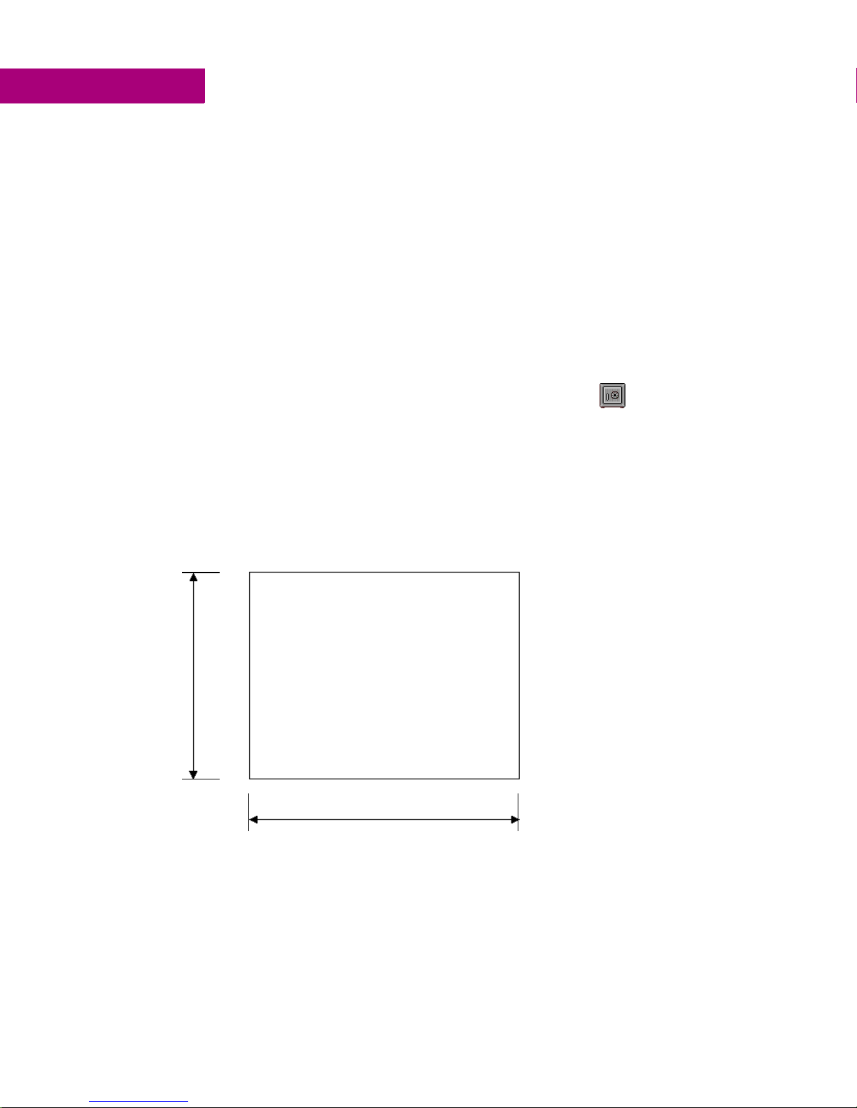
Panel Cutout
For enclosure mounting, cut an opening in the panel according to the following
specifications.
Pan el C uto ut
Height: 4.86” (+ 0.103”, -0”)
(123. 5mm [+2.6mm, -0mm])
Width 6.14” (+ 0.55 ”, - 0”)
4.86”
123 . 5 mm
6.14”
156 m m
The unit will not fit through this cutout with a CF card inserted in the port, with any
cables connected, or with the power supply plug inserted in the socket. To secure
(156mm , [ +14mm, -0m m])
Depth 2.76” (70 mm)
Bezel Dimensions
Height: 6.17” (156.7mm )
Width: 8 in. (203.2mm)
Panel thicknes s range:
to.196” (1.6mm to 5mm)
.063”
4 6" QuickPanel View GFK-2325
Page 11

Welcome
Getting Started
the QuickPanel View to a panel, use the four included mounting brackets. They
hook into openings located on the top and bottom of the housing.
Bottom
Top
To mount the QuickPanel View in a panel
1. Verify that the gasket is properly seated in the bezel channel, then insert the unit into the panel cutout (without a CF
card in the CF port).
2. Insert the hook of each mounting bracket in the housing openings as shown below.
3. Firmly tighten the screws.
Notes:
■
The torque range for the mounting bracket screws is 2.6-4.4 inch/lbs
(0.3-0.5 Nm)
■
For compliance to NEMA 4, 4x and 12 qualification, the unit must be mounted
in a comparably NEMA rated (IP56 or equivalent) panel or enclosure.
■
For compliance to ATEX agency qualification, the unit must be mounted in an
IP66 panel or enclosure.
■
Do not damage the gasket attached to the back of the unit’s bezel. This gasket
prevents shock hazards and damage caused by liquids accidentally entering the
unit after installation. Also, limit the number of times you remove and reinstall
the unit. Too many installations may cause gasket “set” and degradation of the
seal. The mounting clips hold the unit in place by tension alone. No drilling is
required.
GFK-2325 6" QuickPanel View 5
Page 12

Welcome
1
Technical Support
TECHNICAL SUPPORT
If you have technical problems that cannot be resolved with the information in this
guide, please contact us by telephone, fax, or email; or visit one of the links on our
website:
Telephone: 1-800-GE-FANUC (1-800-433-2682)
Fax: (780) 420-2049
Email: support@gefanuc.com
Comments about our manuals or help: doc@gefanuc.com
Web: www.gefanuc.com/support (to locate the Technical Advisor page and a list of
supporting devices (CF cards, etc.) click on the Operator Interface Product Family
link or choose QuickPanel View from the Product List).
For GE Fanuc support, you can also visit:
http://iglobalcare.gefanucautomation.com.
6 6" QuickPanel View GFK-2325
Page 13

2
Overview
This chapter provides introductory information on the 6" QuickPanel View
hardware and software with descriptive procedures for completing some of the
most common tasks you will encounter.
In this chapter:
QUICKPANEL VIEW HARDWARE . . . . . . . . . . . . . 8
Layout Diagram 8
Block Diagram 9
QUICKPANEL VIEW SOFTWARE . . . . . . . . . . . . . 10
Windows CE.NET 10
Working with Windows CE 10
To place a program in the Start menu 11
Pocket Internet Explorer 11
To configure a dial-up connection 11
To configure a Proxy server 12
Backup 13
To run the Backup program 13
To reboot the system 13
Storage Manager 14
System Information 14
To run the System Information program 14
Copy Project to Flash Card 15
To copy a Machine Edition project onto a CF card 15
To update a Machine Edition project 15
Emulate PPC 15
To use Emulate PPC during an ActiveSync session 15
HTTP File Transfer Utility 16
To use the HTTP utility 16
GFK-2325 6" QuickPanel View 7
Page 14
Overview
2
QuickPanel View Hardware
QUICKPANEL VIEW HARDWARE
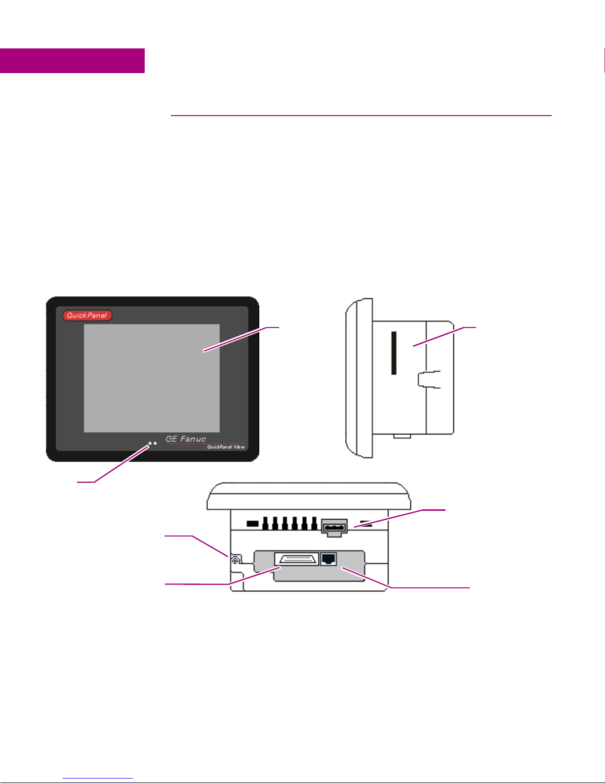
Layout Diagram
In addition to the primary touch screen interface, the 6" QuickPanel View supports
a variety of communication ports including an expansion bus to allow great
flexibility in application. The following diagram shows the physical layout of the
QuickPanel View and the locations of ports and connections
LEDs
Hinged access cover for
expansion (see page 39), and
battery (see page 45)
The left LED below the display is green when power is applied and amber if the
backlight fails;
Front Right Side
1
the right LED is tricolor (green, red, or amber) and programmable.
Touch screen LCD
display. See
page 20
Bottom
CF Port. See page 34
Power supply socket.
See page 2
RS232/485 port
(COM1). See
page 29
Note: On color STN models (IC754VxI06STD), the LEDs are located on the right
side of the LCD display, with the bottom LED indicating power.
1
Backlight is not field replaceable.
8 6" QuickPanel View GFK-2325
Ethernet port.
See page 35
Page 15

Overview
QuickPanel View Hardware
Block Diagram
The 6" QuickPanel View is based on the Intel® XScale™ PXA255 microprocessor,
and employs large-scale integration to provide high performance with a small
footprint. The following block diagram illustrates the major functional areas of the
QuickPanel View and the interfaces between them.
GFK-2325 6" QuickPanel View 9
Page 16

Overview
2
QuickPanel View Software
QUICKPANEL VIEW SOFTWARE
Windows CE.NET
Microsoft Windows CE.NET is the operating system for the QuickPanel View. It is a
full 32-bit O/S with a graphical user interface. This operating system is finding
widespread application in hand-held PCs and embedded HMIs, such as the
QuickPanel View. From a user’s perspective, the familiar look and feel of the
Windows CE environment shortens the learning curve for those having experience
with Windows 95/98/NT/2000/ME/XP. From the software developer’s perspective,
the CE environment is a subset of the WIN32 application programming interface,
simplifying the porting of existing software from other versions of Windows.
The QuickPanel View operating system is stored in a 16 MB block of FLASH
memory and is copied to DRAM for execution. The operating system starts
automatically following a power-up or reset of the QuickPanel View.
For more on Windows CE visit www.microsoft.com/windows/embedded/ce.
Working with Windows CE
Although the main user input device when working with Windows CE is the touch
screen, it can often be convenient to use keyboard shortcuts, such as those
described in the following table.
Keyboard Shortcut Action
CTRL+ESC or Opens the Windows CE Start menu. Use arrow keys
ALT+TAB Starts the Task Manager. Use it to quit unresponsive
CTRL+ALT+= Starts the touch screen calibration.
SPACEBAR Equivalent to single-tap.
ENTER Equivalent to double-tap. In a dialog box, equivalent
TAB In a dialog box, select next control.
SHIFT+TAB In a dialog box, select previous control.
CTRL+TAB In a tabbed dialog box, open the next tab.
to select a program and ENTER to run it.
programs.
to OK.
ESC Close dialog box, discarding changes.
ARROW KEYS In a dialog box, select controls or items from a list .
10 6" QuickPanel View GFK-2325
Page 17

To place a program in the Start menu
1. Start Windows Explorer.
2. Navigate to the program you want to place in the Start menu.
3. Tap the program’s icon to select it.
4. From the Edit menu, choose Copy.
5. Navigate to the ’\Windows\Programs\‘ folder.
6. From the Edit menu, choose Paste Shortcut.
7. Run the Backup program to retain the change through a power cycle (see page 13).
Pocket Internet Explorer
Microsoft’s Pocket Internet Explorer is a full featured browser that is fully integrated
with the Windows CE operating system. This browser allows you to connect with
an internet service provider, view web pages and download from FTP sites.
Overview
QuickPanel View Software
Pocket Internet Explorer supports JScript. Java support can be added from thirdparty sources. Pocket Internet Explorer does not support VBScript; however,
VBScript components are included in the operating system and may be used by
third-party applications such as CIMPLICITY Machine Edition.
A connection can be established over an Ethernet network (default) or a dial-up
connection. The Ethernet or dial-up connection must be properly configured.
To configure a dial-up connection
1. Start Pocket Internet Explorer.
2. From the View menu, choose Options.
The Options dialog box appears.
3. On the Auto Dial tab, select the Use AutoDial check box.
4. Choose either the default or a user-defined connection from the list.
5. Tap OK.
GFK-2325 6" QuickPanel View 11
Page 18

2
To configure a Proxy server
Overview
QuickPanel View Software
6. Run the Backup program to save the settings through a power cycle (see page 13).
1. Start Pocket Internet Explorer.
2. From the View menu, choose Options.
The Options dialog box appears.
3. On the Proxy Server tab, select the Use Proxy Server check box.
4. In the Proxy Server box, type the URL of your proxy server (see your ISP or network administrator).
5. In the Port box, type the server’s port number for HTTP access.
6. Select the Bypass Proxy for Local Addresses check box to connect directly to sites like your intranet.
7. Tap OK.
8. Run the Backup program to retain the new settings through a power cycle (see page 13).
12 6" QuickPanel View GFK-2325
Page 19

To run the Backup program
Overview
QuickPanel View Software
Backup
Backup is a utility that saves any changes made to the Windows Registry or
Desktop. This utility is required because, unlike typical handheld Windows CE
platforms, the QuickPanel View is not battery powered. Specifically, the Backup
command does the following:
■
The Windows CE registry (including any control panel settings) is stored in
the Flash registry
■
Any changes (additions) made to the ‘Windows’ subtree of the file system
are stored in the user block of FLASH memory.
The Backup program should be run whenever configuration changes are made to
the operating system or installed applications, and prior to shutting down the
QuickPanel View.
To reboot the system
1. On the desktop, double-tap Backup.
The Backup dialog box appears.
2. Tap OK.
1. Run the Backup program to retain any changes.
2. Tap Start, point to Programs, then the System folder, and tap Reboot .
A confirmation dialog box appears.
3. Tap “Yes”
The operating system restarts.
GFK-2325 6" QuickPanel View 13
Page 20

Overview
2
QuickPanel View Software
Storage Manager
Use Storage Manager to repair or format lost or corrupted data volumes. Storage
Manager can repair data volumes existing either in Compact Flash (CF) or batterybacked SRAM (BBSRAM). Data volumes existing in the main flash file system of
the QuickPanel View may not be repaired by Storage Manager.
Storage Manager, accessed from the Control Panels folder, is a Microsoft product
for which on-line help is available.
System Information
System Information is a custom utility that displays a splash screen with the
following information:
■
Operating System version. For example, ‘Windows CE 4.10’.
■
Platform. Identifies the host hardware, its version and build number.
Tapping More Info on the splash screen opens the Advanced System Information
window, which provides information such as hardware version and serial number,
CPU type and specifications, etc. This information can be especially useful if you
are contacting GE Fanuc Support.
To run the System Information program
1. On the desktop, double-tap System Information.
The System Information splash screen appears.
2. Tap More Info to open the Advanced System Information window, or tap Close to continue.
Network information alone can be viewed by double-tapping the LAN icon
displayed on the taskbar for each connection.
14 6" QuickPanel View GFK-2325
Page 21

Copy Project to Flash Card
RestorePCCard is a custom utility for transferring CIMPLICITYTM Machine EditionTM
Projects between compatible QuickPanel View
To copy a Machine Edition project onto a CF card
1. Ensure there is a blank CF card in the in the CF port.
2. Double tap the Copy Project to Flash Card icon on the desktop.
3. Tap Yes when the Proceed with Copy to CF Card confirmation dialog box appears.
The system copies the project onto the blank CF Card.
To update a Machine Edition project
You can update a Machine Edition project currently stored on the QuickPanel
View with a revision stored on a CF Card.
1. Insert the CF Card containing an upgraded version of the Machine Edition project in the CF port.
QuickPanel View Software
units via CF cards.
Overview
2. Reboot the machine (see page 13).
When a valid project is found on the CF card, you will be prompted to install the
project or skip it. Tap OK to install or Cancel to skip the install and continue to
reboot. If an invalid project is found, an error message appears in a dialog box.
This dialog box must be closed before reboot will continue.
3. Remove the CF Card from the slot.
Emulate PPC
Emulate PPC is a utility that allows the QuickPanel to emulate a Pocket PC 2003
during an ActiveSync session, enabling the download of third-party Pocket PC
2003 software.
To use Emulate PPC during an ActiveSync session
1. Start Windows Explorer, double tap Windows, then double tap EmulPPC.
The Emulate PPC dialog box appears.
2. Start the ActiveSync session. When installation of third-party software is complete, close the dialog box to deactivate
Emulate PPC.
GFK-2325 6" QuickPanel View 15
Page 22

Overview
2
QuickPanel View Software
HTTP File Transfer Utility
The HTTP File Transfer Utility (HFTU) is a small, standalone command line
program that allows you to send and delete files to and from computers over a
network. The HFTU uses the HTTP protocol, so you can even send files to
computers over the Internet.
Run the HTTP utility from a command line prompt, from a batch file (.BAT) or as
an application call in a script. The HTTP utility is an executable (.EXE) file included
in the 6" QuickPanel View’s operating system.
The HTTP utility currently supports two file transfer commands: COPY and
DELETE.
Note: In order to function, the HTTP File Transfer utility requires both
computers to have web servers that support PUT functionality. (Most web
servers support PUT, including the CIMPLICITY Machine Edition web server
installed with the runtimes for View and Logic Developer - PC.) If in doubt,
check the documentation for your web server.
To use the HTTP utility
1. in the Start menu, choose Programs, then choose Command Prompt.
The Command Line editor appears.
2. Type commands as required.
3. Use the following syntax:
HTTPUTIL COPY source destination
Where “source” is the URL of the source file, and “destination” is the URL of the
destination file. For example:
HTTPUTIL COPY \MyFile.txt http://MyServer/webfiles/MyFileBACKUP.txt
16 6" QuickPanel View GFK-2325
Page 23

Overview
QuickPanel View Software
Copies a file called MyFile.txt on drive C: of the local computer to the webfiles
folder under the web server at //MyServer. Note that you can rename a file as you
copy it.
HTTPUTIL DELETE url
Where “url” is the remote URL of the file you want to delete. This URL must use
the “//” or ”HTTP://” syntax. For example:
HTTPUTIL DELETE http://MyServer/webfiles/MyFileBACKUP.txt
Deletes a file called MyFileBACKUP.txt from the webfiles directory under the web
server at HTTP://MyServer.
GFK-2325 6" QuickPanel View 17
Page 24

Page 25

3
Detailed Operation
In this chapter:
Touch Screen Display . . . . . . . . . . . . . . . . . . . . . 20
To adjust the display contrast 20
To set backlight for auto turn off 21
To calibrate the touch screen 22
To set the double-tap sensitivity 23
Keyboard. . . . . . . . . . . . . . . . . . . . . . . . . . . . . . 25
To show/hide the Soft Input Panel 25
To display the Soft Input Panel icon in the system tray 25
To change key configurations 27
Communication Port . . . . . . . . . . . . . . . . . . . . . . 29
To add a new remote networking connection 30
To add a virtual private network or PPP over Ethernet 31
To change the default device properties 32
To change the default TCP/IP settings 33
CF Port . . . . . . . . . . . . . . . . . . . . . . . . . . . . . . . 34
Ethernet. . . . . . . . . . . . . . . . . . . . . . . . . . . . . . . 35
To set an IP address 36
To set up access to a Windows network 37
To access a remote resource on a Windows network 38
Expansion Bus . . . . . . . . . . . . . . . . . . . . . . . . . . 39
DIP Switches . . . . . . . . . . . . . . . . . . . . . . . . . . . 40
To configure startup behavior with DIP switch 2 41
Memory. . . . . . . . . . . . . . . . . . . . . . . . . . . . . . . 42
To add Flash memory with a CF Card 42
To change the DRAM memory allocation 43
To install additional DRAM 44
Other Subsystems . . . . . . . . . . . . . . . . . . . . . . . 45
To access the Power Properties control panel 45
To remove the internal battery 46
To set the real-time clock 46
To display the time on the taskbar 47
GFK-2325 6" QuickPanel View 19
Page 26

Detailed Operation
3
Touch Screen Display
TOUCH SCREEN DISPLAY
The QuickPanel View has an integrated flat-panel color or monochrome display,
depending on model. The color model (IC754VxI06STD) is backlit, measures 5.7"
diagonally, and uses passive STN technology. The monochrome model
(IC754VxI06MTD) is backlit, measures 5.7" diagonally, and uses passive FSTN
technology.
The resolution of the color display is 320 x 240 pixels with 65,536 colors; the
resolution of the monochrome display is 320 x 240 pixels with 256 shades of gray.
A backlight timer is featured on all models, extending backlight life by turning it off
automatically.
To adjust the display contrast
1. In the Control Panel, double-tap Display and choose the Contrast tab.
240 pixels
320 pixels
The Contrast dialog box appears.
20 6" QuickPanel View GFK-2325
Page 27

2. Drag the Contrast slider between Lowest and Highest.
3. Tap OK to exit the control panel.
4. Run the Backup program to save settings through a power cycle (see page 13).
To set backlight for auto turn off
1. In the Control Panel, double-tap Display and choose the Backlight tab.
The Backlight dialog box appears.
Detailed Operation
Touch Screen Display
2. Select Auto turn off backlight while on external power.
3. Tap OK to exit the control panel.
4. Run the Backup program to save settings through a power cycle (see page 13).
GFK-2325 6" QuickPanel View 21
Page 28

Detailed Operation
3
Touch Screen Display
Touch Screen
The QuickPanel View display is coupled to a resistive touch panel with 12-bit
resolution. When the QuickPanel View is properly calibrated, this translates into a
grid of touch cells on the face of the display. Although you can use your finger to
actuate the touch screen, use of a blunt stylus is recommended.
240 cells
To calibrate the touch screen
1. In the Control Panel, double-tap Stylus.
2. Choose the Calibration tab
3. Tap the Recalibrate button.
320 cells
The Stylus Properties dialog box appears.
A cross hair target is displayed.
22 6" QuickPanel View GFK-2325
Page 29

Detailed Operation
Touch Screen Display
4. Follow the directions given to calibrate the touch screen.
5. Tap the screen to preserve the new setting or wait out the time limit to revert to previous settings.
6. Run the Backup program to save the settings through a power cycle (see page 13).
To set the double-tap sensitivity
1. In the Control Panel, double-tap Stylus.
The Stylus Properties dialog box appears.
GFK-2325 6" QuickPanel View 23
Page 30

Detailed Operation
3
Touch Screen Display
2. Choose the Double-Tap tab.
3. Double-tap the grid to enter a setting.
4. Double-tap the test icon to check the setting.
If the test icon doesn’t change when you double-tap it, double-tap the grid again.
5. Tap OK to finish.
6. Run the Backup program to save the settings through a power cycle (see page 13).
24 6" QuickPanel View GFK-2325
Page 31

KEYBOARD
The QuickPanel View can be configured to use a software emulation keyboard as
the operator input device.
Soft Input Panel
The Soft Input Panel (SIP) is a touch screen version of a standard keyboard, which
can be used in place of a standard hardware keyboard.
An icon in the system tray lets you view or hide the SIP.
To show/hide the Soft Input Panel
• On the system tray of the task bar, double-tap the icon. The Soft Input Panel appears/disappears.
Detailed Operation
Keyboard
Show Input Panel icon
Note: When the SIP is visible, it can be dragged around the screen by its title bar to
reveal different parts of the screen that would be obstructed from view by the SIP.
To display the Soft Input Panel icon in the system tray
1. In the Control Panel, double-tap Input Panel.
The Input Panel Properties dialog box appears.
2. Select the Allow applications to change the input panel state check box.
3. Select or clear the Show Input Panel in system tray check box.
4. Tap Reset SIP location to reset the SIP to its original location on the desktop when displayed.
5. Tap OK.
6. Run the Backup program to retain the new setting through a power cycle (see page 13).
The Soft Input Panel has two basic configurations: Small key and Large key.
GFK-2325 6" QuickPanel View 25
Page 32

Detailed Operation
3
Keyboard
Small Key configuration: Provides a standard QWERTY key layout with numeric
keys at the top row as illustrated in the following picture.
Small key: lower case
Uppercase characters are accessed by pressing the
equivalent to holding down the
SHIFT key on a conventional keyboard. The SHIFT
SHIFT key once. This is
key is active while the next key is pressed then reverts back to its unselected state.
The
CAP key does the same thing as SHIFT but does not revert to lower case after
another key is pressed. Rather, the Soft Input Panel remains in the Uppercase mode
until the
SHIFT key
CAP key is pressed again. The CTRL and ALT keys behave the same as the
Small key: upper case
Large Key configuration: Provides alphabetic or numeric keys alone. No numeric
keys are displayed at the top of the alpha panel; alpha keys are not displayed on
the numeric panel.
26 6" QuickPanel View GFK-2325
Large key: lower case
Page 33

Detailed Operation
Keyboard
As with the small key configuration, upper or lower case alpha keys can be
displayed by using the
Large key: upper case
SHIFT key.
Pressing the 123 key once locks the panel in numeric mode until the 123 key is
pressed again.
Large key: numeric
To change key configurations
1. In the Control Panel, double-tap Input Panel.
2. From the Current input method list, choose CE Keyboard.
3. Tap Options.
The Input Panel Properties dialog box appears.
The Soft Keyboard Options dialog box appears.
4. Select Large Keys or Small Keys.
GFK-2325 6" QuickPanel View 27
Page 34

Detailed Operation
3
Keyboard
A preview of the key size is displayed on the dialog box.
5. Tap OK twice to finish.
6. Run the Backup program to save the settings through a power cycle (see page 13).
28 6" QuickPanel View GFK-2325
Page 35

Detailed Operation
Communication Port
COMMUNICATION PORT
The QuickPanel View has one serial data communication port (COM1).
COM1- Serial
The COM1 port is a general purpose bidirectional serial data channel that supports
the EIA232C and EIA485 electrical standards. The COM1 port can be accessed
and configured:
■
as a direct or dial-up remote networking connection.
■
from a user-created application program.
A connection can be configured to reside on a network supporting a TCP/IP
protocol.
A DB25S (female) connector, mounted on the side of the enclosure, provides
standard signals as described in the following table.
Bottom
1 GND - Frame Ground 14 VCC - 5VDC, 0.5A
2 TX - (EIA232C) 15 TXB (EIA485)
3 RX - (EIA232C) 16 RXB (EIA485)
4 RTS - (EIA232C) 17 n/c
5 CTS - (EIA232C) 18 CSB (EIA485)
6 DSR - (EIA232C) 19 ERB (EIA485)
7 SG - Signal Ground 20 DTR (EIA232C)
8 DCD - (EIA232C) 21 CSA (EIA485)
9 TRMRXB (EIA485) 22 ERA (EIA485)
10 RXA (EIA485) 23 n/c
11 TXA (EIA485) 24 n/c
12 n/c 25 n/c
13 n/c
Notes:
■
Pin 14 is fused with a field-replaceable, 1A fast-blow fuse.
■
Twisted pair cabling is required when using EIA485 communications.
■
When using in EIA485 mode, RXA/RXB termination should be used if the unit is
the last node on the 485 network. A termination resistor is included and is used
by connecting pin 9 to pin 10.
■
When using in EIA485 mode, pin 7 (ground) should not be used.
GFK-2325 6" QuickPanel View 29
Page 36

Detailed Operation
3
Communication Port
Working with the COM port
To add a new remote networking connection
1. From the Start menu, tap Settings, then Network and Dial-up Connections.
The Connection window appears.
2. Double-tap Make New Connection.
The Make New Connection wizard appears.
3. Type a name for the new connection.
4. Choose a connection type.
5. Tap Next.
The Modem or Device dialog box appears, depending on the connection type.
or
6. From the list, choose the device or modem you want to use. (If a Modem or Serial CF card is inserted, it will be
available in the device list.)
Yo u c a n Configure your device or TCP/IP Settings at this time if you wish.
7. Tap Finish for direct connection (Device dialog box) or Next for dial-up (Modem dialog box).
30 6" QuickPanel View GFK-2325
Page 37

Detailed Operation
Communication Port
If you are adding a dial-up connection the following dialog box appears.
8. Type the destination Country/region code, Area code, and Phone number in the appropriate boxes.
9. Select or clear the Force Long Distance or Force Local check boxes.
10. Tap Finish.
11. Run the Backup program to save the settings through a power cycle (see page 13).
To add a virtual private network or PPP over Ethernet
1. From the Start menu, tap Settings, then Network and Dial-up Connections.
The Connection window appears.
2. Double-tap Make New Connection.
The Make New Connection wizard appears.
3. Type a name for the new connection.
4. Choose a connection type.
5. Tap Next.
GFK-2325 6" QuickPanel View 31
Page 38

Detailed Operation
3
Communication Port
The VPN or PPPoE Connection window appears, depending on the connection
type.
or
6. Enter the Host Name or IP address for a VPN connection, or a PPPoE Service Name for a PPPoE connection.
You can configure your TCP/IP Settings at this time if you wish.
7. Tap Finish.
8. Run the Backup program to save the settings through a power cycle (see page 13).
To change the default device properties
1. From either the Device or Modem dialog box, tap Configure.
The Device Properties dialog box appears.
2. In the Port Settings tab, choose settings for all connection preferences.
3. If the connection is for terminal emulation, select or clear the terminal-related check boxes.
You can use the QuickPanel View to emulate a terminal attached via a modem link
(Hayes compatible) to COM1. A terminal emulation definition is added as a
unique session.
32 6" QuickPanel View GFK-2325
Page 39

To change the default TCP/IP settings
1. Obtain correct TCP/IP settings from your network administrator.
2. From either the Device, Modem, PPPoE Connection, or VPN Connection dialog box, tap TCP/IP Settings.
The TCP/IP Settings dialog box appears.
3. Use the TCP/IP settings from your internet provider.
Detailed Operation
Communication Port
4. Run the Backup program to save the settings through a power cycle (see page 13).
GFK-2325 6" QuickPanel View 33
Page 40

Detailed Operation
3
CF Port
CF PORT
To enhance the QuickPanel View’s capabilities with additional flash memory, the
unit is equipped with a CF (Compact Flash) Type 2 port on its side.
Right Side
Compact Flash Port
A CF card is inserted in this port with its front facing the front panel of the unit (the
narrow side slot on the card should be toward the top). The card should slide in
easily—to avoid damage, do not force it.
The Copy Project to Flash Card utility (see page 15) lets you transfer Machine
Edition projects between QuickPanel View units via CF Cards.
No Compact Flash cards are supplied with the QuickPanel View. A list of cards
(and other devices) that have been tested and are compatible can be found by
visiting www.gefanuc.com/support and choosing QuickPanel View from the
product list, or by selecting the Operator Interface Product Family link.
34 6" QuickPanel View GFK-2325
Page 41

Detailed Operation
Ethernet
ETHERNET
The QuickPanel View is equipped with a 10/100BaseT auto-negotiate Ethernet port
(IEEE802.3), and you can connect an Ethernet network cable (unshielded, twisted
pair, UTP CAT 5) to the unit via the RJ45 connector on the bottom of the enclosure.
LED indicators on the port indicate channel status. Access to the port is possible
either by Windows CE network communications, or by your custom application.
The following diagram shows the location, orientation, and pin out of the Ethernet
port.
Bottom
1TX_D1 +
2TX_D1 3RX_D2 +
4B1_D3 +
5B1_D3 6RX_D2 7B1_D4 +
8B1_D4 -
LinkActivity
LED LED
There are two methods for setting an IP address on the QuickPanel View:
■
DHCP (Dynamic Host Configuration Protocol). This is the default method that
is carried out automatically.
Note: There must be a DHCP server on the connected network for a valid IP
address to be assigned. Contact your network administrator to ensure correct
DHCP server configuration.
■
Manual method. The user uniquely specifies the numeric addresses for the
QuickPanel View, the Subnet Mask (if applicable), and the Default Gateway.
Note: Use a crossover cable to connect the QuickPanel View to a PC directly;
when connecting to a LAN HUB, use a straight through cable. Contact your
network administrator if you require further information.
GFK-2325 6" QuickPanel View 35
Page 42

To set an IP address
Detailed Operation
3
Ethernet
1. From the Control Panel, tap Network and Dial-up Connections.
The Connection window appears.
2. Select a connection and choose Properties.
The Built-in Ethernet Port Settings dialog box appears.
3. Select a method:
■
Obtain an IP address via DHCP (automatic).
■
Specify an IP address (manual).
4. Enter the IP Address, Subnet Mask and Default Gateway numbers obtained from your network
administrator (manual method only).
5. Tap OK.
6. Run the Backup program to retain the new settings through a power cycle (see page 13).
7. Restart the QuickPanel View.
If the DHCP method was selected, the network server will assign an IP address
while the QuickPanel View is initializing. (You must be connected to the network).
After setting an IP address for the QuickPanel View, you can access any network
drives or shared resources for which you have permission.
36 6" QuickPanel View GFK-2325
Page 43

To set up access to a Windows network
1. In the Control Panel, double-tap System.
The System Properties dialog box appears.
2. On the Device Name tab, in the Device name box, type a unique name for your QuickPanel View. In the Device
description box, type a description.
3. Tap OK.
Detailed Operation
Ethernet
4. In the Control Panel, double-tap Owner.
The Owner Properties dialog box appears.
5. On the Network ID tab, type your assigned User name, Password and Domain.
6. Tap OK.
7. Run the Backup program to retain the settings through a power cycle (see page 13).
GFK-2325 6" QuickPanel View 37
Page 44

Detailed Operation
3
Ethernet
Using Windows CE Explorer, you can now access anything on your local network
for which you have permission.
To access a remote resource on a Windows network
1. Start Windows Explorer.
The Explorer window appears.
2. Type in the Address box, or choose from a list, the path to a remote resource.
For example ‘\\MyRemoteComputer\MyFolder’ specifies the folder named
‘MyFolder’ on a computer with the name ‘MyRemoteComputer’.
3. Press ENTER.
The resource specified is displayed as a collection of files and folders. It can take a
few moments to retrieve the data from your local network.
Note: You can use the NET command from the shell to map a network resource to
the QuickPanel View for frequent access. The resource then appears in the
Network folder.
38 6" QuickPanel View GFK-2325
Page 45

Detailed Operation
Expansion Bus
EXPANSION BUS
An expansion bus is included with the QuickPanel View, and optional modules
that mount directly to it are available. For more information on expansion
modules, contact your distributor.
The expansion bus connectors are accessed by opening the back of the unit.
Back (open)
Expansion Bus
Caution: Remove power from the QuickPanel View before opening the back.
Working on a “live” unit may result in damage to equipment and injury to
personnel. Always use anti-static precautions (i.e. grounded wrist strap) when
accessing the interior of the unit.
Caution: Ensure all pins are properly aligned when inserting expansion cards.
Misalignment could cause damage to the QuickPanel View and/or the expansion
card.
GFK-2325 6" QuickPanel View 39
Page 46

Detailed Operation
3
DIP Switches
DIP SWITCHES
The QuickPanel View is equipped with four DIP switches that each control
separate functions.
DIP switches are set to “OFF” by default in the factory. DIP switch 2 is the Force
Startup switch. Turning this switch on forces the startup applications to run when
the operating system is started.
Back (open)
Dip Switches
Force Startup
When the switch is set to “OFF”, the QuickPanel View operates normally,
displaying the startup splash screen. You can skip running the startup applications
by tapping the “Don’t run StartUp Programs” button on the startup splash screen.
When the switch is set to “ON”, the startup programs are forced to run and the
“Don’t run Startup Programs” button is not available on the startup splash screen.
Note: Do not adjust switches other than switch 2. They are reserved for factory
functions. Also note that the “On” position of the switches is toward the inside of
the unit, “Off” toward the outside edge, and that switch 1 is closest to the bottom.
40 6" QuickPanel View GFK-2325
Page 47

To configure startup behavior with DIP switch 2
Caution: Remove power from the QuickPanel View before opening the back.
Working on a “live” unit may result in damage to equipment and injury to
personnel. Always use anti-static precautions (i.e. grounded wrist strap) when
accessing the interior of the unit.
1. Open the back cover of the QuickPanel View.
2. Locate the DIP switches and set DIP switch 2 to “ON”.
The startup applications are now forced.
Note: Do not adjust the other switches. They are reserved for factory functions.
Detailed Operation
DIP Switches
GFK-2325 6" QuickPanel View 41
Page 48

Detailed Operation
3
Memory
MEMORY
The QuickPanel View supports a variety of memory subsystems to ensure the
requirements of your application are met. All system memory is tied directly to the
microprocessor’s address and data busses for fastest access. To increase DRAM by
up to 64 MB, a 100-pin DIMM memory expansion slot is also included.
Flash Memory
This 32 MB block of non-volatile memory is the main long-term program storage
for the QuickPanel View, operating like a virtual hard drive from the point of view
of Windows CE. It is divided into two areas, of which only one is accessible from
Windows CE Explorer. The Flash Storage folder represents a 16 MB block of
memory available for long-term storage of user application programs. The other 16
MB is used to store the Windows CE operating system, and is not directly
accessible from Windows CE Explorer.
The operating system and all user application programs are transferred from Flash
to DRAM for execution. Any user additions to the Windows folder are retained
in Flash Storage when the Backup utility is run.
FLASH memory has a limited write-cycle lifetime. That is, the physical memory
devices wear out after approximately 100,000 cycles (minimum), so it is advisable
to limit file operations such as copy, delete, etc.
The write cycle is much slower for FLASH than it is for other portions of RAM,
therefore FLASH is not recommended for the storage of program variables, or any
data items whose values are dynamic.
Flash memory can optionally be added with a CF Card, which will appear as the
PCFlash Storage folder.
To add Flash memory with a CF Card
■
Insert a Compact Flash card into CF Port (see page 34).
The unit immediately reads the new secondary storage. If the disk requires
formatting, you will be prompted to do so.
New memory appears in Windows CE Explorer as PCFlash Storage.
42 6" QuickPanel View GFK-2325
Page 49

Detailed Operation
Memory
SRAM Memory
This 512 KB block of static RAM is battery-backed to provide data retention
through a power cycle. The SRAM memory is made available for user applications
by operating as a virtual hard drive and is accessible from the Windows CE
Explorer. It is represented as the SRAM Storage folder. A typical application
program would create a file in this folder and store any critical program data in that
file.
DRAM Memory
The QuickPanel View is equipped with 32 MB of dynamic RAM. Part of the DRAM
(11 MB) is reserved for the Windows CE operating system and is not accessible by
user applications. The other 21 MB is split between two functions: an object store
for temporary file storage, and the main memory for running programs.
Typically, compressed programs stored in FLASH are expanded and moved to
DRAM for execution. Temporary storage of program variables or data files is also
provided by DRAM—any data stored in DRAM will not be retained through a
power cycle.
The split between program memory and storage memory may be adjusted as
necessary to make more room for one or the other, depending on your specific
application needs. For example, if you find that an application is short of memory,
use the System Properties dialog box to alter DRAM memory allocation.
Caution: Setting Program Memory too low may prevent additional applications
from starting , or may cause currently running applications to fail due to lack of
memory. Setting Storage Memory too low may prevent the saving of files into the
object store portion of the file system, which may also cause application failures.
To change the DRAM memory allocation
1. In the Control Panel, double-tap System.
The System Properties dialog box appears.
GFK-2325 6" QuickPanel View 43
Page 50

Detailed Operation
3
Memory
2. On the Memory tab, drag the slider to divide the DRAM into Storage and Program memory.
The amount of memory allocated to and used by each area is displayed
numerically. The blue bar indicates the current amount of unallocated DRAM and
determines the boundaries within which the slider can move.
3. Tap OK to apply the new setting.
4. Run the Backup program to retain the new setting through a power cycle (see page 13).
Boot Loader ROM
The Boot Loader ROM provides 512 KB of non-volatile storage for the QuickPanel
View’s initialization program. This program configures the QuickPanel View
hardware then starts the operating system’s execution. This memory is not
accessible from Windows CE Explorer, nor should any attempts be made to modify
the contents of this ROM.
To install additional DRAM
Memory Expansion Slot
The QuickPanel View is equipped with a 100-pin DIMM memory expansion slot
which lets you increase DRAM to a total of 96 MB.
Back (open)
Memory Expansion Slot
Caution: Remove power from the QuickPanel View before opening the back.
Working on a “live” unit may result in damage to equipment and injury to
personnel. Always use anti-static precautions when accessing the interior of the
QuickPanel View.
1. Disconnect AC power from the 24VDC supply.
2. Open the rear access panel.
3. Insert the new DIMM carefully into the expansion slot, noting the orientation of the pin locators. When the DIMM is
fully seated, lift each side clip until it clicks into place.
44 6" QuickPanel View GFK-2325
Page 51

OTHER SUBSYSTEMS
Power Management
The QuickPanel View’s Power Properties control panel displays the status of the
backup battery. The Battery Very Low Or Missing icon displays in the taskbar
when the battery is either missing or very low.
To access the Power Properties control panel
1. In the Control Panel, double-tap Power.
The Power Properties dialog box appears.
Detailed Operation
Other Subsystems
Battery Backup
Auxiliary backup power for the real-time clock and SRAM is provided by a nonrechargeable, internal lithium battery (+3VDC, CR2032), ensuring that no loss of
data occurs when the main 24VDC supply is removed. Backup power is enabled
or disabled by installing or removing the battery, accessed via the rear panel as
shown in the following illustration.
Rear (open)
Internal Battery
Caution: Remove power from the QuickPanel View before opening the back.
Working on a “live” unit may result in damage to equipment and injury to
personnel. Always use anti-static precautions when accessing the interior of the
QuickPanel View.
GFK-2325 6" QuickPanel View 45
Page 52

3
To remove the internal battery
1. Disconnect AC power from the 24VDC supply.
2. Open the rear access panel.
3. Release the battery by gently lifting it from the completely exposed side, past the small protrusions. To avoid
4. Slide the battery out of its carrier, noting the arrow on the carrier indicating the direction of removal.
Detailed Operation
Other Subsystems
breaking the battery retainer clips, do not apply excessive upward pressure.
Real-time Clock
The QuickPanel View has a programmable real-time clock capable of reporting the
current time in Year/Month/Day/Hour/Minute/Second. The time is set from the
Windows CE interface and retained through a power cycle if battery backup is
available. Automatic adjustment for daylight savings time is enabled by a check
box within the dialog box. The time can be displayed in the system tray on the task
bar.
To set the real-time clock
1. In the Control Panel, double-tap Date/Time.
The Date/Time Properties dialog box appears.
Note: Tap Apply after making changes in any box.
2. Tap the year to choose a new year; tap the month to choose a new month.
3. Tap a date to specify the day of month.
4. From the Time Zone box, choose your zone.
5. Select Auto Adjust DST to have the clock automatically compensate for daylight savings time.
6. In the Current Time box, adjust the hours, minutes and seconds.
7. Tap OK to finish.
46 6" QuickPanel View GFK-2325
Page 53

To display the time on the taskbar
1. From the Start menu, choose Settings, then Taskbar and Start Menu....
The Taskbar Properties dialog box appears.
2. On the Tas kba r Options tab, select Show Clock.
3. Tap OK.
An hours and minutes display now appears in the taskbar.
Detailed Operation
Other Subsystems
Clock Display
GFK-2325 6" QuickPanel View 47
Page 54

Page 55

A1
Design Specifications
The specifications listed in this appendix are the design goals for the QuickPanel
View. In most cases the “as built” or tested specifications are identical. See page
53 for a list of agency approvals for environmental service and safety.
Physical
Enclosure dimensions Height: 4.86 in (126mm)
Width: 6.14 in (158mm)
Depth: 2.76 in (70mm)
Bezel dimensions Height: 6.17 in (156.7mm)
Width: 8 in (203.2mm)
Depth: 0.85 in (21.5mm)
Weight 2.5lb (1.16 kg)
DC Power
Input Voltage 10.8 to 30 VDC (12 VDC +/- 10% regulated
power supply; 24 VDC +/- 20% power supply)
Real Power 12 W
Power requirement nominal for startup when DC supply is
already powered and stable. Applying power to the supply
while connected to the QuickPanel View increases total
inrush current requirements. In this case, supply should be
rated at 10x the nominal startup current. Otherwise, an
interposing relay or switch must be used between the DC
supply and the QuickPanel View.
NOTE : For compliance with UL 1604, switches or relays inline with the DC power wiring cannot be used in hazardous
locations.
Connector (Vendor, p/n) Phoenix Contact, 1777992
Power Supply Conductor Size 12 to 18 AWG
For compliance to CE Mark, the isolated frame ground must
be connected.
Recommended frame ground connection is via the shortest
possible route, using a 14 AWG conductor.
GFK-2325 6" QuickPanel View 49
Page 56

A1
Design Specifications
Display
Size 5.75” 14.6 cm
Colors 65,536 (color)
256 shades of gray (monochrome)
Resolution 320 X 240
Fabrication Passive STN transmissive (color)
Passive FSTN (monochrome)
Backlight Cold Cathode Fluorescent (CCFL) - rated half
life: 40,000 hours (color)
Cold Cathode Fluorescent (CCFL) - rated half
life: 50,000 hours (monochrome)
Backlight not field replaceable.
Front Panel
Bezel Material Valox 357U
For material specifications, visit
www.gepolymerland.com
Membrane Material Lexan HP60
For material specifications, visit
gestructuredproducts.com
LEDs
Left (bottom on color model)
Power status indicator (green with power
applied, amber if backlight fails)
Right (top on color model)
Programmable tri-color (green, red, amber)
Touch Screen
Type Resistive, 12 bit
Resolution X axis- 320 cells
Y axis - 240 cells
(after calibration)
CPU
Processor Intel XScale PXA255
Clock speed 300 Mhz
50 6" QuickPanel View GFK-2325
Page 57

Memory
FLASH 32 MB
SRAM 512KB (Battery Backed)
DRAM 32 MB
ROM 512 KB (Boot loader)
Memory Expansion Slot
Form Factor 100 pin DIMM
Memory Type SDRAM
Maximum DRAM 64 MB
Maximum Devices/Module 4
Bus Width 32 bits
Design Specifications
Bus Speed 100 MHz or faster
Voltage 3.3 VDC
CAS Latency CL=3
Refresh Cycle Time 64 ms maximum
Error Correction Non-ECC
Error Detection No parity
Buffering None
Device Row Addressing 12 Address Lines (A0 to A11)
Expansion Memory Catalog
Number
32MB - IC754ACC32MEM
64MB - IC754ACC64MEM
Expansion Ports
Compact Flash Memory One slot (type 2)
Expansion Bus One slot
GFK-2325 6" QuickPanel View 51
Page 58

A1
Design Specifications
Communication Port
Ethernet IEEE 802.3
10/100BaseT
RJ45 connector
Two status LEDs
Maximum cable length: 30M
Serial COM1
Speed
Mounting h/w
Fuse
EIA232C/EIA485, DP25S (female)
300 bps - 115200 bps
M2.6 jackscrew
1.0A, 125V fast blow cartridge type, Littlefuse
part #154001
Environmental
Mono Color
Operating Temperature 14°F to 140°F
(-10°C to 60°C)
Operating Humidity 10% to 85%, non-
condensing
Storage Temperature -4 to 158°F
-20 to 70 °C
Storage Humidity 10% to 85%, non-
condensing
NEMA Rating 4, 4x, and 12 when
mounted in a panel
(IP65 equivalent)
32°F to 140°F
(0°C to 60°C)
10% to 90%, noncondensing
-4 to 140°F
-20 to 60 °C
10% to 90%, noncondensing
4, 4x, and 12 when
mounted in a panel (IP65
equivalent)
Operational Vibration IEC 68-2-6
Operational Shock IEC 68-2-27
Battery
Type CR2032 (3V, 190mAh, lithium)
Life (Approximate) 5 years
52 6" QuickPanel View GFK-2325
10 - 57Hz, 0.012” peak
to peak displacement
57 - 500Hz, 1.0g
acceleration
15g, 11ms (sine wave)
IEC 68-2-6
10 - 57Hz, 0.012” peak
to peak displacement
57 - 500Hz, 1.0g
acceleration
IEC 68-2-27
15g, 11ms (sine wave)
Page 59

Calendar/Clock
Resolution 1 second
Retention Life of battery
Agency Qualifications
Model # ES0611 (color)
Model # ES0601 (mono)
Design Specifications
Description
North American Safety
for Industrial Control
Equipment
North American Safety
for Hazardous
Locations Class I, Div.
2, Groups A, B, C, D
Enclosures for Electrical
Equipment
Explosive Atmospheres
Directive
European Safety for
Hazardous Locations
Equipment Group II,
Category 3
Low Voltage Directive
European Safety for
Industrial Control
Equipment
Agency Standard
or Marking
Comments
UL 508/C-UL Certification by
Underwriter’s Laboratories
to UL standard and
equivalent CSA standard
UL 1604/C-UL Certification by
Underwriter’s Laboratories
to UL standard and
equivalent CSA standard
UL 50 Certification by
Underwriter’s Laboratories
to Type 4, 4X
ATEX (when
mounted in an IP66rated panel)
Certification in accordance
with European directives;
refer to Declaration of
Conformity and
rd
Independent 3
Party
Assessment Certificate
CE Self-declaration in
accordance with European
directives; refer to
Declaration of Conformity
Electromagnetic
Compatibility Directive
European EMC for
Industrial Control
Equipment
GFK-2325 6" QuickPanel View 53
CE Certification by competent
body in accordance with
European directives; refer to
Declaration of Conformity
Page 60

Page 61

A2
Troubleshooting
The tables contained in this appendix can be used to identify and remedy
problems that can occur with the 6" QuickPanel View.
Power up
Problem Suggested remedy
Blank screen. Check all power connections to the QuickPanel View.
Note:
Left LED glows amber when backlight fails.
Pocket Internet Explorer
Problem Suggested remedy
Cannot access any URLs when using
a dial-up connection to an ISP.
If you have previously set up an IP address on a local
Ethernet Network, it must be cleared. Disconnect your
Ethernet cable and reboot.
Your ISP will reassign an IP address when you reconnect
the cable.
GFK-2325 6" QuickPanel View 55
Page 62

Page 63

Index
A
accessing
Windows network 37, 38
adding
connections 30, 31
addresses
IP 36
adjusting
display contrast 20
B
backlight
(note) 8, 50
set for auto turn off 21
backup 13
battery 45
specifications 52
status 45
baud rate 32
bezel 50
block diagram 9
boot loader ROM 44
C
calibrating
touch screen 22
CIMPLICITY Machine Edition 15
clock 46
COM1 29
communication ports 29, 52
locations 8
compact flash
adding memory 42
configuring
set IP address 36
TCP/IP settings 33
connections
adding 30, 31
set IP address 36
TCP/IP settings 33
Windows network 37
contrast 20
cutout 4
see also design specificatons
D
design specifications 49
device properties, configuring 32
DHCP (Dynamic Host
Configuration Protocol) 35
dial-up connection 30
dip switches 40
displaying
real-time clock 47
double-tap sensitivity
setting 22, 23
DRAM 43
partition DRAM memory 43
partitioning 43
E
Emulate PPC 15
Ethernet 35
port settings 36
expansion bus 39
expansion busses
locations 8
expansion ports 51
Explorer, Internet 11
F
flash 42
flow control 32
front panel 8, 50
bezel 50
LEDs 8, 50
membrane 50
I
input panel 25
displaying 25
Internet Explorer 11
IP address
setting 36
K
key configurations
changing 27
large 26
small 26
keyboard 25
keyboard shortcuts 10
L
LEDs
Ethernet 35, 52
front panel 8, 50
M
Machine Edition 15
membrane 50
memory 42, 51
adding with CF card 42
boot loader ROM 44
DRAM 43
flash 42
partition DRAM memory 43
SRAM 43
memory expansion slot 44
modem configuration 30
mounting
GFK-2325 6" QuickPanel View 57
Page 64

Index
dimensions 4
hardware 5
mounting directions 5
mounting brackets 5
P
panel cutout 4
see also design specifications
parity 32
partitioning
DRAM 43
physical layout 8
Pocket Internet Explorer 11
ports
communication 29, 52
Ethernet 35
expansion 51
keyboard 25
locations 8
serial 29
power management 45
control panel 45
power supply 2
power supply terminals
location 8
PPPoE 31
product support 6
programs
start menu 11
proxy server 12
R
real-time clock 46
displaying 47
setting 46
S
serial ports 29
setting
double-tap sensitivity 23
sensitivity 22
IP address 36
real-time clock 46
setup
basic 2
runtime 3
shutdown 4
specifications 49
SRAM 43
start menu 11
startup 3
configuring behavior 41
force startup switch 40
stop startup programs 40
storage card 42, 43
storage manager 14
support 6
switches, dip 40
System Information 14
T
Technical Advisor 6
technical support 6
terminal emulation 32
touch screen 22
calibrating 22
troubleshooting 55
U
utilities
backup 13
System Information 14
V
virtual private network 31
W
Windows CE 10
Windows network
accessing 37, 38
58 6" QuickPanel View GFK-2325
 Loading...