

Page 1

GE Fanuc Automation
Computer Numerical Control Products
Alpha Series AC Servo Motor
Parameter Manual
GFZ-65150E/04 December 1999
Page 2

Warnings, Cautions, and Notes
as Used in this Publication
Warning notices are used in this publication to emphasize that hazardous voltages, currents,
temperatures, or other conditions that could cause personal injury exist in this equipment or
may be associated with its use.
In situations where inattention could cause either personal injury or damage to equipment, a
Warning notice is used.
Caution notices are used where equipment might be damaged if care is not taken.
GFL-001
Warning
Caution
Note
Notes merely call attention to information that is especially significant to understanding and
operating the equipment.
This document is based on information available at the time of its publication. While efforts
have been made to be accurate, the information contained herein does not purport to cover all
details or variations in hardware or software, nor to provide for every possible contingency in
connection with installation, operation, or maintenance. Features may be described herein
which are not present in all hardware and software systems. GE Fanuc Automation assumes
no obligation of notice to holders of this document with respect to changes subsequently made.
GE Fanuc Automation makes no representation or warranty, expressed, implied, or statutory
with respect to, and assumes no responsibility for the accuracy, completeness, sufficiency, or
usefulness of the information contained herein. No warranties of merchantability or fitness for
purpose shall apply.
©Copyright 1999 GE Fanuc Automation North America, Inc.
All Rights Reserved.
Page 3

B-65150E/04 DEFINITION OF WARNING, CAUTION, AND NOTE
DEFINITION OF WARNING, CAUTION, AND NOTE
This manual includes safety precautions for protecting the user and preventing damage to the m achine.
Precautions are classified into Warning and Caution according to their bearing on safety. Also,
supplementary information is described as a Note. Read the Warning, Caution, and Note thoroughly
before attempting to use the machine.
WARNING
CAUTION
NOTE
!
s-1
Page 4

CONTENTS
B-65150E/04
DEFINITION OF WARNING, CAUTION, AND NOTE.................................s-1
1 OVERVIEW.............................................................................................. 1
1.1 SERVO SOFTWARE AND MODULES SUPPORTED BY EACH NC MODEL ........................................2
1.2 ABBREVIATIONS OF THE NC MODELS COVERED BY THIS MANUAL...............................................4
1.3 RELATED MANUALS..............................................................................................................................5
2 SETTING α SERIES SERVO PARAMETERS ......................................... 7
2.1 INITIALIZING SERVO PARAMETERS....................................................................................................7
2.1.1 Before Servo Parameter Initialization............................................................................................................. 7
2.1.2 Parameter Initialization Flow......................................................................................................................... 8
2.1.3 Servo Parameter Initialization Procedure....................................................................................................... 9
2.1.4 Setting Servo Parameters When a Separate Detector for the Serial Interface Is Used.................................. 23
2.1.5 Actions for Invalid Servo Parameter Setting Alarms.................................................................................... 29
3 α SERIES PARAMETER ADJUSTMENT............................................... 39
3.1 SERVO ADJUSTMENT SCREEN..........................................................................................................40
3.2 ACTIONS FOR ALARMS.......................................................................................................................43
3.3 PROCEDURES FOR GAIN ADJUSTMENT AND VIBRATION-DAMPING CONTROL..........................50
3.3.1 Gain Adjustment Procedure.......................................................................................................................... 50
3.3.2 Vibration in the Stop State........................................................................................................................... 53
3.3.3 Vibration during Travel................................................................................................................................ 55
3.3.4 Cumulative Feed...........................................................................................................................................57
3.3.5 Overshoot..................................................................................................................................................... 58
3.4 ADJUSTING PARAMETERS FOR HIGH SPEED AND HIGH PRECISION...........................................59
3.4.1 Level-up HRV Control Adjustment Procedure ............................................................................................ 59
3.4.2 Cutting Feed/Rapid Traverse Switchable Function...................................................................................... 67
3.4.3 Servo Parameter Adjustment Procedure for Achieving High Speed and High Precision............................. 71
3.4.4 High-Speed Positioning Adjustment Procedure........................................................................................... 84
3.4.5 Rapid Traverse Positioning Adjustment Procedure...................................................................................... 87
4 SERVO FUNCTION DETAILS ............................................................... 92
4.1 LIST OF SERVO FUNCTIONS..............................................................................................................93
4.2 HRV CONTROL.....................................................................................................................................96
4.3 LEVEL-UP HRV CONTROL.................................................................................................................101
4.4 VIBRATION SUPPRESSION FUNCTION IN THE STOP STATE........................................................103
4.4.1 250 µsec Acceleration Feedback Function................................................................................................. 103
4.4.2 Velocity Loop High Cycle Management Function..................................................................................... 104
4.4.3 Function for Changing the Proportional Gain in the Stop State ................................................................. 107
4.4.4 N Pulse Suppression Function.................................................................................................................... 110
−
Page 5

CONTENTS B-65150E/04
4.5 MACHINE-RESONANCE SUPPRESSION FUNCTION.......................................................................112
4.5.1 Machine Speed Feedback Function............................................................................................................ 112
4.5.2 Observer Function...................................................................................................................................... 116
4.5.3 Torque Command Filter.............................................................................................................................120
4.5.4 Dual Position Feedback Function...............................................................................................................122
4.5.5 Vibration-damping Control Function......................................................................................................... 130
4.5.6 Vibration Suppression Filter Function....................................................................................................... 133
4.5.7 Current Loop 1/2PI Function .....................................................................................................................134
4.6 SHAPE-ERROR SUPPRESSION FUNCTION.....................................................................................137
4.6.1 Feed-forward Function ..................................................................................................... .......................... 137
4.6.2 Advanced Preview Feed-forward Function................................................................................................ 141
4.6.3 RISC Feed-forward Function..................................................................................................................... 144
4.6.4 Backlash Acceleration Function................................................................................................................. 146
4.6.5 Two-stage Backlash Acceleration Function ............................................................................................... 149
4.6.6 Static Friction Compensation Function...................................................................................................... 160
4.7 OVERSHOOT COMPENSATION ........................................................................................................162
4.8 HIGH-SPEED POSITIONING FUNCTION...........................................................................................171
4.8.1 Position Gain Switch Function................................................................................................................... 171
4.8.2 Low-speed Integration Function................................................................................................................. 175
4.8.3 Fine Acceleration/Deceleration (FAD) Function........................................................................................ 177
4.9 DUMMY SERIAL FEEDBACK FUNCTIONS........................................................................................188
4.9.1 Dummy Serial Feedback Functions............................................................................................................ 188
4.9.2 How to Use the Dummy Feedback Functions for a Multiaxis Servo Amplifiers
When an Axis Is Not in Use....................................................................................................................... 191
4.10 BRAKE CONTROL FUNCTION...........................................................................................................192
4.11 STOP DISTANCE REDUCTION FUNCTION.......................................................................................197
4.11.1 Emergency Stop Distance Reduction Function Type 1.............................................................................. 197
4.11.2 Emergency Stop Distance Reduction Function Type 2.............................................................................. 200
4.11.3 Separate Detector Hardware Disconnection Stop Distance Reduction Function........................................201
4.11.4 OVL and OVC Alarm Stop Distance Reduction Function......................................................................... 204
4.11.5 Overall Use of the Stop Distance Reduction Functions..............................................................................204
4.12 ABNORMAL-LOAD DETECTION FUNCTION.....................................................................................205
4.12.1 Abnormal-load Detection Function............................................................................................................ 205
4.12.2 Unexpected Disturbance Detection Performed Separately for Cutting and Rapid Traverse....................... 214
4.13 FUNCTION FOR OBTAINING CURRENT OFFSETS AT EMERGENCY STOP..................................216
4.14 LINEAR MOTOR PARAMETER SETTING ..........................................................................................217
4.14.1 Procedure for Setting the Initial Parameters of Linear Motors................................................................... 217
4.14.2 Linear Motor Thrust Ripple Correction......................................................................................................225
4.15 TORQUE CONTROL FUNCTION........................................................................................................232
4.16 USAGE OF THE SERVO SOFTWARE FOR SUPER-PRECISION MACHINING................................235
4.17 TANDEM CONTROL FUNCTION........................................................................................................242
4.17.1 Preload Function ........................................................................................................................................ 248
4.17.2 Damping Compensation Function.............................................................................................................. 251
4.17.3 Velocity Feedback Averaging Function..................................................................................................... 254
−
Page 6

B-65150E/04 CONTENTS
4.17.4 Servo Alarm 2-axis Simultaneous Monitor Function................................................................................. 255
4.17.5 Motor Feedback Sharing Function............................................................................................................. 255
4.17.6 Full-closed Loop Feedback Sharing Function............................................................................................ 256
4.17.7 Full Preload Function................................................................................................................................. 257
4.17.8 Position Feedback Switching Function ......................................................................................................262
4.17.9 Adjustment................................................................................................................................................. 264
4.17.10 Notes on Tandem Control.......................................................................................................................... 268
4.17.11 Block Diagrams.......................................................................................................................................... 270
4.18 SERVO AUTO TUNING.......................................................................................................................272
4.19 SERVO CHECK BOARD OPERATING PROCEDURE........................................................................278
5 DETAILS OF PARAMETERS .............................................................. 291
5.1 DETAILS OF Series 0-C AND 15-A SERVO PARAMETERS (9041, 9046 SERIES)...........................292
5.2 DETAILS OF THE SERVO PARAMETERS FOR Series 15, 16, 18, 20, 21, Power Mate
(SERIES 9060, 9064, 9065, 9066, 9070, 9080, 9081, 9090, AND 90A0)............................................299
6 PARAMETER LIST.............................................................................. 317
6.1 FOR Series 0-C AND 15-A ..................................................................................................................318
6.2 PARAMETERS FOR STANDARD CONTROL.....................................................................................326
6.3 PARAMETERS FOR HRV CONTROL.................................................................................................334
APPENDIX
A DIFFERENCES BETWEEN THE PARAMETERS
FOR THE Series 15-A AND Series 15-B (15i-A) ................................ 347
B ANALOG SERVO INTERFACE SETTING PROCEDURE ................... 350
C PARAMETERS SET WITH VALUES IN DETECTION UNITS.............. 355
C.1 PARAMETERS FOR Series 15i...........................................................................................................356
C.2 PARAMETERS FOR Series 15-B........................................................................................................358
C.3 PARAMETERS FOR Series 16, 18, AND 21.......................................................................................360
C.4 PARAMETERS FOR Series 0-C..........................................................................................................361
C.5 PARAMETERS FOR THE Power Mate i..............................................................................................362
C.6 PARAMETERS FOR THE Power Mate -E...........................................................................................363
D FUNCTION-SPECIFIC SERVO PARAMETERS .................................. 364
−
Page 7

B-65150E/04 1. OVERVIEW
1 OVERVIEW
This manual describes the servo parameters of the following NC
models using an α servo system. The descriptions include the servo
parameter start-up and adjustment procedures. The meaning of each
parameter is also explained.
− 1 −
Page 8

1. OVERVIEW B-65150E/04
1.1 SERVO SOFTWARE AND MODULES SUPPORTED BY
EACH NC MODEL
NC product name
Series 0-MODEL C
Series 15-MODEL A
Series 15-MODEL B (Note 2)
Series 16-MODEL A
Series 18-MODEL A
Series 20-MODEL A
Series 21-MODEL A
Series 21-MODEL B
Power Mate-MODEL D
Power Mate-MODEL F
Power Mate-MODEL H
Power Mate-MODEL I
Series 15-MODEL B (Note 2)
Series 16-MODEL B
Series 18-MODEL B
Series 16-MODEL C
Series 18-MODEL C
Series 15-B (FS15-B) (Note 2)
Series 16-C (FS16-C)
Series 18-C (FS18-C)
Series 16i -MODEL A (Note 3)
Series 18i -MODEL A
Series 21i -MODEL A
Power Mate i -MODEL D
Power Mate i -MODEL H
Series 15i-MODEL A
Power Mate-MODEL E (PME)
Series and edition of applicable servo
software
Series 9046/A(01) and subsequent editions
(Supporting standard and high-speed
positioning)
Series 9041/A(01) and subsequent editions
(Supporting dual position feedback)
Series 9060/J(10) and subsequent editions 320C25 module
Series 9060/J(10) and subsequent editions
(Supporting standard and high-speed
positioning)
Series 9066/F(06) and subsequent editions
(Supporting FAD & HRV control) (Note 1)
Series 9070/A(01) and subsequent editions
Series 9080/E(05) and subsequent editions
(Supporting FAD & HRV control and linear
motor)
Series 9081/A(01) and subsequent editions
(Supporting SUPER-precision machining)
Series 9090/A(01) and subsequent editions
(Supporting i series CNC)
Series 90A0/A(01) and subsequent editions
(Supporting i series CNC and level-up HRV
control)
Series 90A0/A(01) and subsequent editions
(Supporting i series CNC and level-up HRV
control)
Series 9064/E(05) and subsequent editions
(Standard)
Series 9065/A(01) and subsequent editions
(Supporting HRV control)
Serial axis board
320C25 module
320C51 module
320C52 module
320C52 module
320C52 servo card
320C543 servo card
320C543 servo card
Module
− 2 −
Page 9

B-65150E/04 1. OVERVIEW
NOTE 1 For some models of the Series 21, Power Mate-D, and
Power Mate-F, the NC software and servo software are
integrated.
The NC software of the following series and editions
includes servo software supporting the α servo motor.
Series21-TA Series 8866/001B and subsequent editions
Series21-TB control A type Series DE01/001A and subsequent editions
Power Mate-D
Power Mate-F Series 8870/001A and subsequent editions
Series 8831/001A and subsequent editions
Series 8836/001A and subsequent editions
NOTE 2 The servo software series of the Series 15-B depends on the
incorporated servo module, as shown below:
Servo software CNC CPU Servo module
Series 9060 68030 320C25 module
Series 9070 68040 320C51 module
Series 9080
Series 9081
68040 320C52 module
NOTE 3 The servo software series of the Series 16i, 18i, 21i, and
Power Mate i depend on the incorporated servo card, as
shown below.
Servo software Servo card
Series 9090 320C52 card
Series 90A0 320C543 card
− 3 −
Page 10

1. OVERVIEW B-65150E/04
1.2 ABBREVIATIONS OF THE NC MODELS COVERED BY
THIS MANUAL
The models covered by this manual, and their abbreviations are :
NC product name Abbreviations
FANUC Series 0-MODEL C Series 0-C Series 0
FANUC Series 15-MODEL A Series 15-A
FANUC Series 15-MODEL B Series 15-B
FANUC Series 15i-MODEL A
FANUC Series 16-MODEL A Series 16-A
FANUC Series 16-MODEL B Series 16-B
FANUC Series 16-MODEL C Series 16-C
FANUC Series 16i-MODEL A
FANUC Series 18-MODEL A Series 18-A
FANUC Series 18-MODEL B Series 18-B
FANUC Series 18-MODEL C Series 18-C
FANUC Series 18i-MODEL A
FANUC Series 20-MODEL A Series 20-A Series 20
FANUC Series 21-MODEL A Series 21-B
FANUC Series 21-MODEL B Series 21-C
FANUC Series 21i-MODEL A
FANUC Power Mate-MODEL D Power Mate-D
FANUC Power Mate-MODEL F Power Mate-F
FANUC Power Mate-MODEL H Power Mate-H
FANUC Power Mate-MODEL I Power Mate-I
FANUC Power Mate i-MODEL D Power Mate i-D
FANUC Power Mate i-MODEL H Power Mate i-H
FANUC Power Mate-MODEL E Power Mate-E
Series 15i-A
Series 16i-A
Series 18i-A
Series 21i-A
Series 15 (Note 1)
Series 16 (Note 1)
Series 18 (Note 1)
Series 21 (Note 1)
Power Mate (Note 2)
Power Mate-E
(Note 2)
NOTE
1 In this manual, a reference to the Series 15, 16, 18, or
21, without a specific model name refers to all the
models of the series.
2 In this manual, Power Mate refers to the Power
Mate-D, Power Mate-F, Power Mate-H, Power Mate-I,
Power Mate i-D, and Power Mate i-H.
The Power Mate-E, which uses different servo
software and different parameter numbers, is
designated by its full name or as Power Mate-E.
− 4 −
Page 11

B-65150E/04 1. OVERVIEW
1.3 RELATED MANUALS
The following ten kinds of manuals are available for FANUC SERV O
MOTOR α/β series.
In the table, this manual is marked with an asterisk (*).
Table 1. Related manuals of SERVO MOTOR α/β series
Document name Document
FANUC AC SERVO MOTOR α series
DESCRIPTIONS
FANUC AC SERVO MOTOR β series
DESCRIPTIONS
FANUC AC SPINDLE MOTOR α series
DESCRIPTIONS
FANUC SERVO AMPLIFIER α series
DESCRIPTIONS
FANUC CONTROL MOTOR AMPLIFIER α series
(SERVO AMPLIFIER UNIT)
DESCRIPTIONS
FANUC CONTROL MOTOR α series
MAINTENANCE MANUAL
FANUC CONTROL MOTOR AMPLIFIER α series
(SERVO AMPLIFIER UNIT)
MAINTENANCE MANUAL
FANUC SERVO MOTOR β series
MAINTENANCE MANUAL
FANUC AC SERVO MOTOR α series
PARAMETER MANUAL
FANUC AC SPINDLE MOTOR α series
PARAMETER MANUAL
number
B-65142E
B-65232EN
B-65152E
B-65162E
B-65192EN
B-65165E
B-65195EN
B-65235EN
B-65150E
B-65160E
Major contents Major usage
• Specification
• Characteristics
• External dimensions
• Connections
• Specification
• Characteristics
• External dimensions
• Connections
• Specification
• Characteristics
• External dimensions
• Connections
• Specifications and
functions
• Installation
• External dimensions
and maintenance
area
• Connections
• Start up procedure
• Troubleshooting
• Maintenance of motor
• Start up procedure
• Troubleshooting
• Start up procedure
• Troubleshooting
• Maintenance of motor
• Initial setting
• Setting parameters
• Description of
parameters
• Initial setting
• Setting parameters
• Description of
parameters
• Selection of motor
• Connection of
motor
• Selection of
amplifier
• Connection of
amplifier
• Start up the
system
(Hardware)
• Troubleshooting
• Maintenance of
motor
• Start up the
system
(Hardware)
• Troubleshooting
• Start up the
system
(Hardware)
• Troubleshooting
• Maintenance of
motor
• Start up the
system (Software)
• Turning the
system
(Parameters)
*
− 5 −
Page 12
1. OVERVIEW B-65150E/04
Other manufactures’ products referred to in this manual
* IBM is registered trademark of International Business Machines
Corporation.
* MS-DOS and Windows are registered trademarks of Microsoft
Corporation.
* 486SX and 486DX2 are registered trademarks of Intel corporation.
All other product names identified throughout this manual are
trademarks or registered trademarks of their respective companies.
In this manual, the servo parameters are explained using the following
notation:
(Example)
No. 1875
No. 2021
Series 0-CSeries 15
No. 8X21
No. 1021
Servo parameter function name
Load inertia ratio
Series16, 18, 20, 21
Power Mate
Power Mate-E
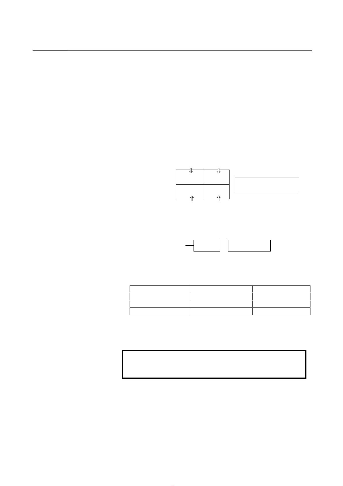
The α servo motor can take either of the following configurations:
α
motor
+
α
pulse coder
The following α pulse coders are available.
Pulse coder name Resolution Type
αA64 65,536 pulse/rev Absolute
αI64 65,536 pulse/rev Incremental
αA1000 1,000,000 pulse/rev Absolute
When parameters are set, these pulse coders are all assumed to have a
resolution of 1,000,000 pulses per motor revolution.
NOTE
The αA1000 is used for 0.1-µm detection control and
high-speed high-precision control.
− 6 −
Page 13

B-65150E/04 2. SETTING α SERIES SERVO PARAMETERS
2 SETTING α SERIES SERVO PARAMETERS
2.1 INITIALIZING SERVO PARAMETERS
2.1.1 Before Servo Parameter Initialization
Before starting servo parameter initialization, confirm the following:
<1> NC model (ex.: Series 15-B)
<2> Servo motor model (ex.:
<3> Pulse coder built in a motor (ex.:
<4> Is the separate position detector used? (ex.: Not used)
<5> Distance the machine tool moves per revolution of the motor
(ex.: 10 mm per one revolution)
<6> Machine detection unit (ex.: 0.001 mm)
<7> NC command unit (ex.: 0.001 mm)
α 6/2000)
α A1000)
− 7 −
Page 14
2. SETTING α SERIES SERVO PARAMETERS B-65150E/04
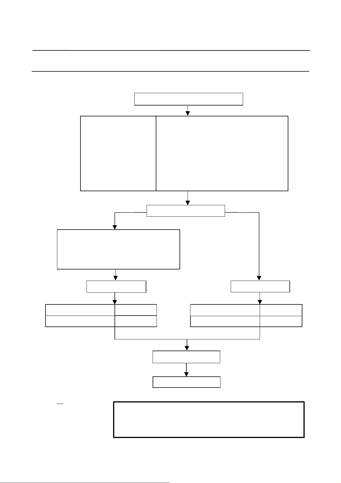
2.1.2 Parameter Initialization Flow
On the servo setting and servo adjustment screens, set the following:
In emergency stop state, switch on NC.
Initialization bits
Motor No.
AMR
CMR
Move direction
Reference counter
Velocity gain
Make settings for using separate detector.
No. 1807#3 = 1, 1815#1 = 1 (Series 15)
Set bits 0 to 3 of No. 37 to 1. (Series 0-C)
No. 1815#1 = 1 (Series 16, 18, 21, Power Mate)
No. 1002 = 10001000 (Power Mate-E)
Set flexible feed gear.
00000000 (except Power Mate-E) (Note)
00011000 (for Power Mate-E)
See (4) in Subsec. 2.1.3.
00000000
See (6) in Subsec. 2.1.3.
111 (Clockwise as viewed from detector)
−111 (Counterclockwise as viewed from detector)
See (10) in Subsec. 2.1.3.
Set 100% if the machine inertia is unknown.
(Equivalent to load inertia ratio parameter)
Which system is being used?
← See (7) in Subsec. 2.1.3. →
Semi-closed loopClosed loop
Set flexible feed gear.
Number of velocity pulses
Number of position pulses
8192 (Note)
Ns (Note)
For the phase A/B separate
detector and serial linear scale:
Ns: Number of feedback pulses per motor
revolution, received from the separate
detector
For the serial rotary scale:
Ns: 12500 × (motor-to-table deceleration ratio)
Example: When the motor rotates ten turns while
the table rotates one turn
1
12500 × = 1250
10
Set Ns to 1250.
NOTE
When initialization bit 0 is set to 1, the settings of the
number of velocity pulses and the number of position
pulses must be reduced by a factor of 10.
Number of velocity pulses
Number of position pulses
Turn power off then on.
End of parameter setting
− 8 −
8192 (Note)
12500 (Note
Page 15

B-65150E/04 2. SETTING α SERIES SERVO PARAMETERS
2.1.3 Servo Parameter Initializ ati on Procedure
(1) Switch on the NC in an emergency stop state.
Enable parameter writing (PWE = 1).
(2) Initialize servo parameters on the servo setting screen.
For a Power Mate with no CRT, specify a value for an item
number on the servo setting screen. See Fig. 2.1.3.
To display the servo setting screen, follow the procedure below,
using the key on the NC.
Series 0-C
0389 SVS
SVS (#0) 0: Displays the servo screen.
Series 15
Series 16, 18, 20, 21
3111 SVS
SVS (#0) 1: Displays the servo screen.
Press the key several times, and the serv o setting screen w ill
PARAM
appear.
If no servo screen appears, set the following parameter as shown, and
switch the NC off and on again.
#7 #6 #5 #4 #3 #2 #1 #0
SERVICE
Press the key several times, and the servo setting screen will
appear.
SYSTE
→ [SYSTEM] → [ ] → [SV-PRM]
If no servo screen appears, set the following parameter as shown, and
switch the NC off and on again.
#7 #6 #5 #4 #3 #2 #1 #0
− 9 −
Page 16
2. SETTING α SERIES SERVO PARAMETERS B-65150E/04
When the following screen appears, move the cursor to the item you
want to specify, and enter the value directly.
Servo set
X axis
INITIAL SET BITS
Motor ID No.
AMR
CMR
Feed gear N
(N/M) M
Direction Set
Velocity Pulse No.
Position Pulse No.
Ref. counter
Fig. 2.1.3 Servo setting menu Correspondence of Power Mate
00001010
00000000
8192
12500
10000
16
2
1
100
111
01000 N0000
Z axis
00001010
16
00000000
2
1
100
111
8192
12500
10000
Power Mate Power Mate-E
No. 2000
2020
2001
1820
2084
2085
2022
2023
2024
1821
No. 1000
1020
1001
100
1084
1085
1022
1023
1024
324
(3) Start initialization.
#7 #6 #5 #4 #3 #2 #1 #0
INITIAL SET BIT PRMC DGPR PLC0
( Note)
Start initialization (Keep the NC power on until step (11).)
DGPR (#1) = 0 Automatically set to 1 after initialization.
NOTE
Once initialization has been completed, the Series
0-C and Series 15-A automatic al ly set bit 3 (PRMC )
for initialization to 0, while other NC models set the
bit to 1. Note that the bit 3 (PRMC) bit must be set to
0 for the Series 0-C and Series 15-A.
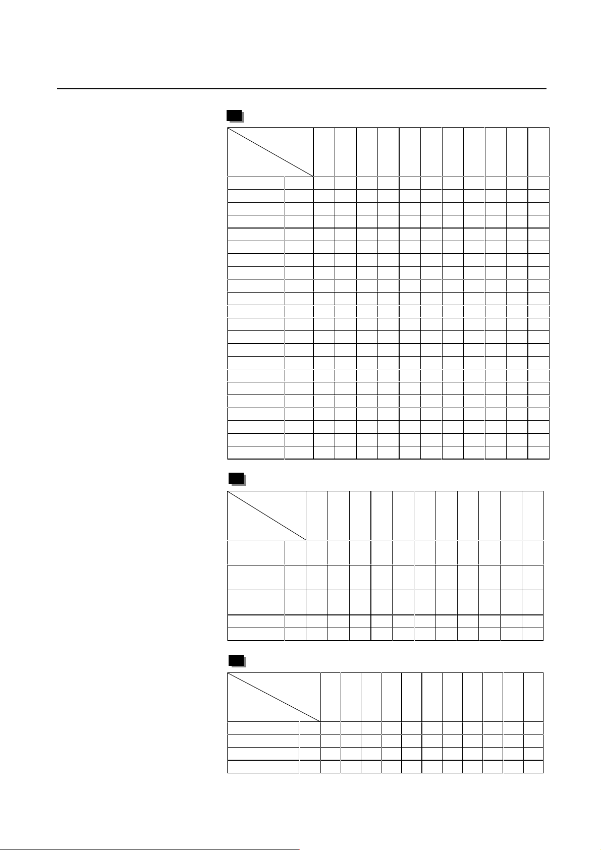
(4) Specify the motor ID No.
Select the motor ID No. of the servo motor to be used, according
to the motor model and drawing num ber (the m iddle four dig its of
A06B-XXXX-BXXX) listed in the tables on subsequent pages.
− 10 −
Page 17
B-65150E/04 2. SETTING α SERIES SERVO PARAMETERS
α series servo motor
Motor model α1/3000 α2/2000 α2/3000 α2.5/3000 α3/3000
Motor
specification
Motor type No. 61 46 62 84 15
Motor model α6/2000 α6/3000 α12/2000 α12/3000 α22/1500
Motor
specification
Motor type No. 16 17 18 19 27
Motor model α22/2000 α22/3000 α30/1200 α30/2000 α30/3000
Motor
specification
Motor type No.2021282223
Motor model α40/FAN α40/2000 α65 α100 α150
Motor
specification
Motor type No. 29 30 39 40 41
0371 0372 0373 0374 0123
0127 0128 0142 0143 0146
0147 0148 0151 0152 0153
0158 0157 0331 0332 0333
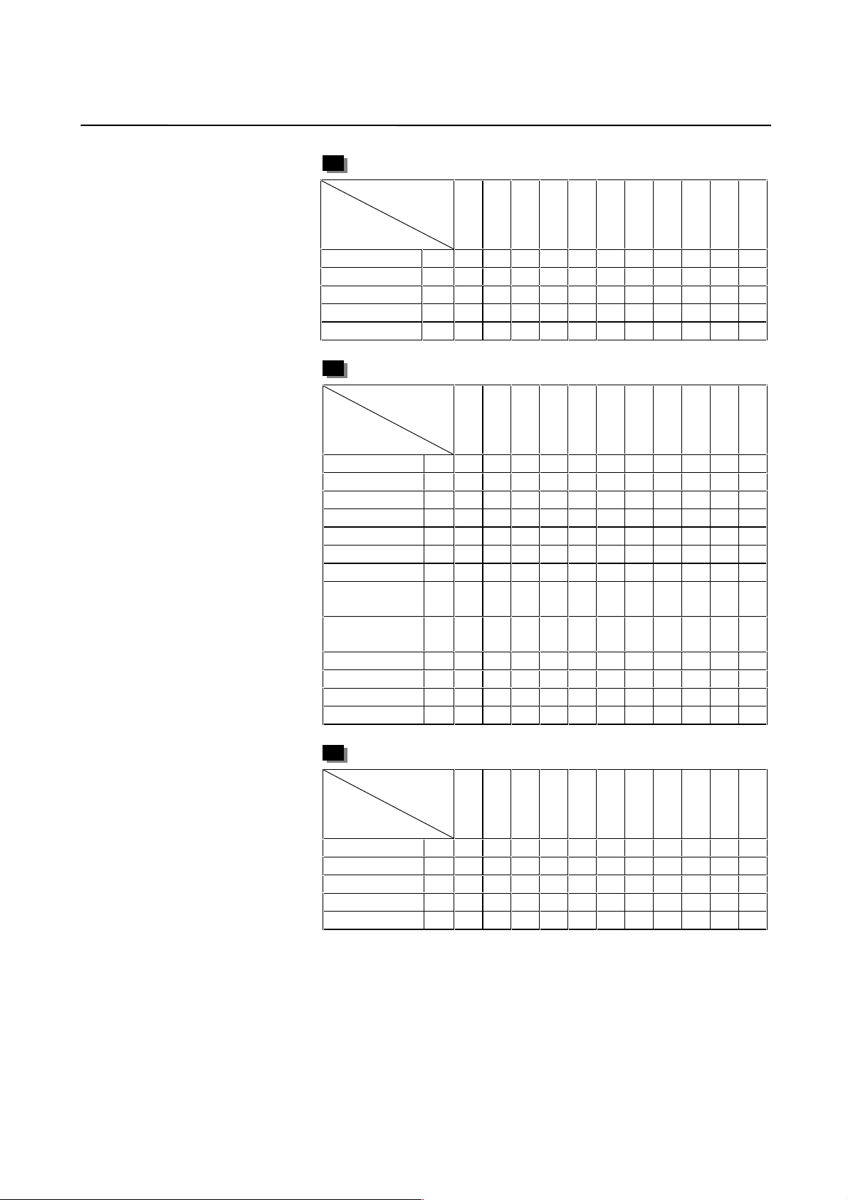
Motor model α300/2000 α400/2000
Motor
specification
Motor type No. 111 112
αL series servo motor
Motor model αL3/3000 αL6/3000 αL9/3000 α
Motor
specification
Motor type No. 56 or 68* 57 or 69* 58 or 70* 59 60
0561 0562 0564 0571 0572
0337 0338
L25/3000αL50/2000
Use the motors mark ed by * with the serv o software that supports HRV
control (Series 9066, 9080, 9081, 9090, and 90A0).
αC series servo motor
Motor model αC3/2000 αC6/2000 αC12/2000 αC22/1500
Motor
specification
Motor type No. 7 8 9 10
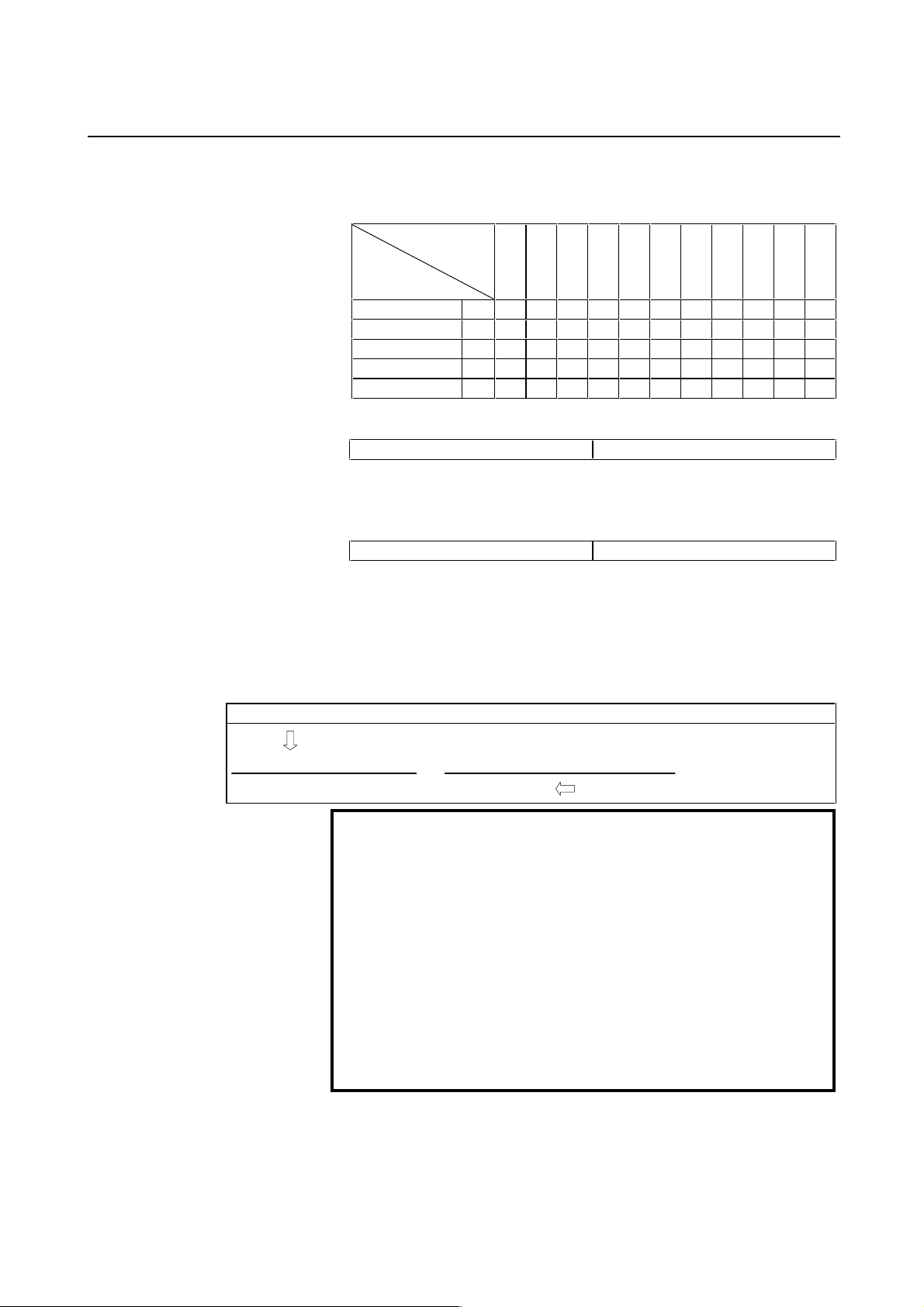
αHV series servo motor
Motor model α3HV α6HV α12HV α22HV α30HV
Motor
specification
Motor type No. 1 2 3 102 103
0121 0126 0141 0145
0171 0172 0176 0177 0178
− 11 −
Page 18

2. SETTING α SERIES SERVO PARAMETERS B-65150E/04
αM series servo motor
Motor model αM2/3000 α
Motor
specification
Motor type No.9899242526
Motor model α
Motor
specification
Motor type No. 100 101 108 110
Motor model αM6HV αM9HV αM22HV αM30HV
Motor
specification
Motor type No. 104 105 106 107
Linear motor
Motor model 1500A 3000B 6000B 9000B 15000C
Motor
specification
Motor type No.9091929394
0376 0377 0161 0162 0163
M22/3000αM30/3000
0165 0166 170 170
0182 0183 0185 0186
0410 0411 0412 0413 0414
M2.5/3000
αM3/3000 αM6/3000 αM9/3000
αM40/3000FAN
(360A amplifier
driving)
αM40/3000
(130A amplifier
driving)
Remark)
β series servo motor
Motor model β0.5 β1/3000 β2/3000 β3/3000 β6/2000
Motor
specification
Motor type No.1335363334
0113 0031 0032 0033 0034
These motor type Nos. may not be supported depending on the servo
software being used.
The following lists the motor type Nos. together with the applicable
servo software series and editions.
− 12 −
Page 19
B-65150E/04 2. SETTING α SERIES SERVO PARAMETERS
α series servo motor
Servo software
Motor series
model and
motor type number
9
0
0
0
0
0
0
0
0
0
0
0
6
6
A
9
8
8
7
6
6
4
4
5
4
0
0
1
0
0
6
0
6
1
9
9
9
9
9
9
9
9
9
9
α1/3000 61 A B M A C A C A A E A
α2/2000 46 A B M A C A C A A E A
α2/3000 62 A B M A C A C A A E A
α2.5/3000 84 A B M A C A C A A E A
α3/3000 15 A B M A C A C A A E A
α6/2000 16 A B M A C A C A A E A
α6/3000 17 A B M A C A C A A E A
α12/2000 18 A B M A C A C A A E A
α12/3000 19 A B M A C A C A A E A
α22/1500 27 A B M A C A C A A E A
α22/2000 20 A B M A C A C A A E A
α22/3000 21 A B M A C A C A A E A
α30/1200 28 A B M A C A C A A E A
α30/2000 22 A B M A C A C A A E A
α30/3000 23 A B M A C A C A A E A
α40/FAN 29 ABMACACAAEA
α40/2000 30 A B M A C A C A A E A
α65 39ABMACACAAEA
α100 40 A B M A C A C A A E A
α150 41 A B M A C A C A A E A
α300/2000 111 Y M K
α400/2000 112 Y M K
αL series servo motor
Servo software
Motor series
model and
motor type number
9
0
0
0
0
0
0
0
0
0
0
0
6
6
A
9
8
8
7
6
6
4
4
5
4
0
0
1
0
0
6
0
6
1
9
9
9
9
9
9
9
9
9
9
αL3/3000 5668ABMAICAKCEAAAAEA
αL6/3000 5769ABMAICAKCEAAAAEA
αL9/3000 5870ABMAICAKCEAAAAEA
αL25/3000 59 A B M A C A C A A E A
αL50/3000 60 A B M A C A C A A E A
αC series servo motor
Servo software
Motor series
model and
motor type number
9
0
0
0
0
0
0
0
0
0
0
0
6
6
A
9
8
8
7
6
6
4
4
5
4
0
0
1
0
0
6
0
6
1
9
9
9
9
9
9
9
9
9
9
αC3/2000 7 A B M A C A C A A E A
αC6/2000 8 A B M A C A C A A E A
αC12/2000 9 A B M A C A C A A E A
αC22/1500 10 A B M A C A C A A E A
− 13 −
Page 20
2. SETTING α SERIES SERVO PARAMETERS B-65150E/04
αHV series servo motor
9
9
9
9
9
9
9
9
9
9
Servo software
Motor series
model and
motor type number
α3HV 1 W B M A A A A F A
α6HV 2 W B M A A A A F A
α12HV 3 A B M A C A C A A E A
α22HV 102 I K E D A
α30HV 103 I K E D A
αM series servo motor
Servo software
Motor series
model and
motor type number
αM2/3000 98 I K E D A
αM2.5/3000 99 I K E D A
αM3/3000 24 A B M A C A C A A E A
αM6/3000 25 A B M A C A C A A E A
αM9/3000 26 A B M A C A C A A E A
αM22/3000 100 I K E D A
αM30/3000 101 I K E D A
αM40/3000
(360A driving)
αM40/3000
(130A driving)
αM6HV 104 I K E D A
αM9HV 105 I K E D A
αM22HV 106 I K E D A
αM30HV 107 I K E D A
9
0
0
0
0
0
0
0
0
9
8
8
7
6
6
4
4
0
1
0
0
6
0
6
1
9
9
9
9
9
9
9
9
0
0
0
0
0
0
0
0
9
8
8
7
6
6
4
4
0
1
0
0
6
0
6
1
108 Y L D
110 Y L D
0
0
0
6
6
A
5
4
0
9
9
9
0
0
0
6
6
A
5
4
0
Linear motor
9
9
9
9
9
9
9
Servo software
Motor series
model and
motor type number
1500A 90 D A A A A
3000B 91 D A A A A
6000B 92 D A A A A
9000B 93 D A A A A
15000C 94 K S J C
9
0
0
0
0
0
0
0
0
9
8
8
7
6
6
4
4
0
1
0
0
6
0
6
1
− 14 −
9
9
9
0
0
0
6
6
A
5
4
0
Page 21
B-65150E/04 2. SETTING α SERIES SERVO PARAMETERS
Reference)
β series servo motor
9
9
9
9
9
9
9
9
9
9
Servo software
Motor series
model and
motor type number
β0.5/3000 13 A B M A C A C A A E A
β1/3000 35 A B M A C A C A A E A
β2/3000 36 A B M A C A C A A E A
β3/3000 33 G W B H A C A A F A
β6/2000 34 A B M A C A C A A E A
9
0
0
0
0
0
0
0
0
0
0
0
6
6
A
9
8
8
7
6
6
4
4
5
4
0
0
1
0
0
6
0
6
1
(5) Set AMR as described below:
α pulse coder 00000000
(6) Set CMR with the scale of a distance the NC instructs the machine
to move.
CMR = Command unit / Detection unit
CMR 1/2 to 48 Setting value = CMR × 2
Usually, CMR = 1, so specify 2.
(7) Specify the flexible feed gear (F⋅FG ). This function m akes it easy
to specify a detection unit for the leads and gear reduction ratios
of various ball screws by changing the number of position
feedback pulses from the pulse coder or separate detector.
Setting for the α pulse coder in the semi-closed mode
F⋅FG numerator (≤ 32767) per motor revolution
= (as irreducible fraction)
F⋅FG denominator (≤ 32767) 1,000,000 (Note 2)
(Note 1) Necessary position feedback pulses
NOTE
1 For both F⋅FG number and denominator, the maximum
setting value (after reduced) is 32767.
2 α pulse coders assume one million pulses per motor
revolution, irrespective of resolution, for the flexible
feed gear setting.
3 If the calculation of the number of pulses required per
motor revolution involves π, such as when a rack and
pinion are used, assume π to be approximately
355/113.
4 The setting for serial pulse coder A is the same as for
the α pulse coder.
− 15 −
Page 22

2. SETTING α SERIES SERVO PARAMETERS B-65150E/04
Example of setting
For detection in 1 µm units, specify as follows:
Ball screw lead
(mm/rev)
10
20
30
Number of necessary
position pulses
(pulses/rev)
10000
20000
30000
F⋅FG
1/100
2/100 or 1/50
3/100
Example of setting
If the machine is set to detection in 1,000 degree units with a gear
reduction ratio of 10:1 for the rotation axis, the table rotates by 360/10
degrees each time the motor makes one turn.
1000 position pulses are necessary for the table to rotate through one
degree.
The number of position pulses necessary for the motor to make one turn
is:
360/10 × 1000 = 36000 with reference counter = 36000
F⋅FG numerator 36000 36
==
F⋅FG denominator 1,000,000 1000
Setting for use of a separate detector (full-closed)
F⋅FG numerator (≤ 32767) to a predetermined amount of travel
F⋅FG denominator (≤ 32767) Number of position pulses corresponding
Number of position pulses corresponding
= (as irreducible fraction)
to a predetermined amount of travel from
a separate detector
DMR can also be used with the parallel type separate position detector,
provided that F⋅FG = 0.
Example of setting
To detect a distance of 1 µm using a 0.5-µm scale, set the following:
Numerator of F⋅FG L/1 1
= =
Denominator of F⋅FG L/0.5 2
(8) Specify the direction in which the motor rotates.
111 Clockwise as viewed from the pulse coder
−111 Counterclockwise as viewed from the pulse coder
− 16 −
Page 23

B-65150E/04 2. SETTING α SERIES SERVO PARAMETERS
(9) Specify the number of velocity pulses and the number of position
pulses.
Full-closed
Command
unit (µm)
Initialization
bit
Number of
velocity
pulses
Number of
position
pulses
Semi-closed
1 0.1 1 0.1 1 0.1 1 0.1
b0 = 0 b0 = 0 b0 = 0 b0 = 0 b0 = 1 b0 = 0 b0 = 1 b0 = 0 b0 = 0
8192 8192 8192 8192 819 8192 819 8192 8192
12500 12500 12500 Ns Ns/10 Ns Ns/10 Np Np
Parallel type
Serial liner
scale
Serial rotary
scale
Ns : Number of position pulses from the separate detector when
the motor makes one turn
Np: 12500 × (motor-to-table deceleration ratio or acceleration
ratio)
(Example: When the motor rotates ten turns while the table
rotates one turn: Np = 12500/10 = 1250)
Series 0−C
Conventionally, the initialization bit, bit 0 (high-resolution bit), was
changed according to the command unit. The command unit and
initialization bit 0 have no longer been interrelated with each other in
all CNCs except the Series 0-C and Series 15-A.
Of course, the conventional setting method may also be used. For
easier setting, however, set the bit as follows:
Semi-closed: Initialization bit bit 0 = 0
Full-closed: Initialization bit bit 0 = 1
Only when the number of position pulses exceeds
32767.
In the above table, the number of position pulses is likely to exceed
32767 when the command unit is 0.1 µm in full-closed mode.
When using a separate detector (full-closed mode), also specify the
following parameters:
(When using t he separate serial detector, see Subsec. 2.1.4.)
#7 #6 #5 #4 #3 #2 #1 #0
0037 STP8 STP7 STP4 STPZ STPY STPX
STPX to 8 (#0 to #5) The separate position detector is:
0: Not used for the X-axis, Y-axis, Z-axis, fourth axis, seventh axis,
or eighth axis
1: Used for the X-axis, Y-axis, Z-axis, fourth axis, seventh axis,
and eighth axis
− 17 −
Page 24

2. SETTING α SERIES SERVO PARAMETERS B-65150E/04
Series 15, 16, 18, 20, 21,
Power Mate
#7 #6 #5 #4 #3 #2 #1 #0
1807 PFSE
−
↑ Must be specified only for Series 15.
PFSE (#3) The separate position detector is:
0: Not used
1: Used
CAUTION
This parameter is used only for Series 15.
#7 #6 #5 #4 #3 #2 #1 #0
1815 OPTX
↑
Must be specified for all NCs.
OPTX (#1) The separate position detector is:
0: Not used
1: Used
Power Mate−E
NOTE
For Series 16, 18, 20, and 21, setting this parameter
causes bit 3 of parameter No. 2002 to be set to 1
automatically.
#7 #6 #5 #4 #3 #2 #1 #0
1002 GRSL PFSE
−
GRSL (#7) The separate position detector is:
PFSE (#3) 0: Not used
1: Used
Specify the same value for both GRSL and PFSE.
(10) Specify the reference counter.
The reference counter is used in making a return to the reference
position by a grid method.
Semi-closed loop
Count on the
reference counter
Number of position pulses corresponding to a
=
single motor revolution or the same number
divided by an integer value
− 18 −
Page 25

B-65150E/04 2. SETTING α SERIES SERVO PARAMETERS
Example of setting
α pulse coder and semi-closed loop (1-µm detection)
Ball screw lead
(mm/revolution)
10
20
30
Necessary number of
position pulses
(pulse/revolution)
10000
20000
30000
Reference
counter
10000
20000
30000
Grid width
(mm)
10
20
30
When the number of position pulses corresponding to a single motor
revolution does not agree with the reference counter setting, the
position of the zero point depends on the start point.
Should this occur, eliminate the difference by changing the detection
unit.
Example of setting
System using a detection unit of 1 µm, a ball screw lead of 20
mm/revolution, a gear reduction ratio of 1/17, the number of position
pulses corresponding to a single motor revolution set to 1176.47, and
the reference counter set to 1176
In this case, increase all the following parameter values by a factor of
17, and set the detection unit to 1/17 µm.
Parameter modification Series 0-C
FFG
CMR
Reference counter
Effective area
Position error limit in traveling
Position error limit in the stop state
Backlash
Servo screen
Servo screen
Servo screen
Nos. 500 to 503
(All other CNC parameters set in detection units, such as the amount of
grid shift and pitch error compensation magnification, are also
multiplied by 17.)
CAUTION
In addition to the above parameters, there are some
parameters that are to be set in detection units.
For details, see Appendix C.
Making these modifications eliminates the difference between the
number of position pulses corresponding to a single motor revolution
and the reference counter setting.
Number of position pulses corresponding to a single motor revolution =
20000
Reference counter setting = 20000
504 to 507
593 to 596
535 to 538
Series 15, 16,
18, 20, 21,
Power Mate
Servo screen
Servo screen
Servo screen
Nos. 1826, 1827
1828
1829
1851, 1852
Power
Mate-E
Nos. 1084, 1085
100
324
200
202
231
221
− 19 −
Page 26

2. SETTING α SERIES SERVO PARAMETERS B-65150E/04
CAUTION
In rotation axis control for the Series 16, 18, and
Power Mate, continuous revolution in the same
direction will result in an error if the result of the
following calculation is other than an integer, even if
the reference counter setting is an integer. Therefore,
set parameter No. 1260 so that the result of the
calculation is an integer.
(Amount of travel per rotation of the rotation axis
(parameter No. 1260)) × CMR ×
21
6
(reciprocal of flexible feed gear) × 2
/10
This problem has been corrected in the following
system software version and later versions:
B0F2/04 (16iM)
B1F2/04 (16iT)
BDF2/04 (18iM)
BEF2/04 (18iT)
DDF2/04 (21iM)
DEF2/04 (21iT)
Full-closed loop
Reference counter
setting
Z-phase (reference-position) interval divided by
=
the detection unit, or this value sub-divided by an
integer value
Example of setting
Example 1) When the Z-phase interval is 50 mm and the detection
unit is 1 µm:
Reference counter setting = 50,000/1 = 50,000
Example 2) When a rotation axis is used and the detection unit is
0.001°:
Reference counter setting = 360/0.001 = 360,000
Example 3) When a linear scale is used and a single Z phase exists:
Set the reference counter to 10000, 50000, or another
round number.
(11) When using an S-series amplifier, set the following parameters:
#7 #6 #5 #4 #3 #2 #1 #0
1809 8X04 DLY1 DLY0 TIB1 TIB2 TRW1 TRW0 TIB0 TIA0
2004 1004 01000110
(↑ S-series amplifier)
1866 8X54 Current dead band compensation (PDDP)
2054 1054
Set value 3787 (S-series amplifier)
− 20 −
Page 27

B-65150E/04 2. SETTING α SERIES SERVO PARAMETERS
(12) Switch the NC off and on again.
This completes servo parameter initialization.
If an invalid servo parameter setting alarm occurs, go to Subsec.
2.1.4.
If a servo alarm related to pulse coders occurs for an axis for
which a servo motor or amplifier is not connected, specify the
following parameter.
A feedback connector is used in conventional Series 0-C and 15A models. However it cannot be used in a system designed for
operation with an
α pulse coder.
This parameter should be specified instead of the dummy
connector.
#7 #6 #5 #4 #3 #2 #1 #0
1953 8X09 SERD
2009 1009
SERD (#0) The dumm y serial feedback function is: (See Sec. 4.6 for function detail)
0 : Not used
1 : Used
Series 0−C
0021 APC8 APC7 APC4 APCZ APCY APCX
APCX to 8 (#0 to #5) The absolute position detector is:
Series 15, 16, 18, 20, 21,
Power Mate
1815 APCX
APCX (#5) The absolute position detector is:
(13) When you are going to use an
α pulse coder as an absolute pulse
coder, use the following procedure.
This procedure is somewhat different from one for conventional
pulse coders. (Steps 3 to 5 have been added.)
1. Specify the following parameter, then switch the NC off.
#7 #6 #5 #4 #3 #2 #1 #0
0: Not used for the X-axis, Y-axis, Z-axis, fourth axis, seventh axis,
or eighth axis.
1: Used for the X-axis, Y-axis, Z-axis, fourth axis, seventh axis, and
eighth axis.
#7 #6 #5 #4 #3 #2 #1 #0
0: Not used
1: Used
− 21 −
Page 28

2. SETTING α SERIES SERVO PARAMETERS B-65150E/04
Power Mate−E
#7 #6 #5 #4 #3 #2 #1 #0
0017 APCX
APCX (#0) An absolute position detector is:
0: Not used
1: Used
2. After making sure that the battery for the pulse coder is
connected, switch the NC on.
3. A request to return to the reference
position is displayed.
4. Cause the motor to make one turn by jogging.
5. Turn off and on the CNC.
These steps
were added
for the α
pulse coder.
6. A request to return to the reference position is displayed.
7. Do the zero return.
− 22 −
Page 29

B-65150E/04 2. SETTING α SERIES SERVO PARAMETERS
2.1.4 Setting Servo Parameters When a Separate Detector for the
Serial Interface Is Used
(1) Overview
When a separate detector of the serial output type is used, there is a
possibility that the detection unit becomes finer than the detection unit
currently used. Accordingly, a few modifications are made to the
setting method and values of servo parameters.
When using a separate detector of the serial output type, follow the
method explained below to set parameters.
(2) Series and editions of applicable servo software
Series 9080/M (13) and subsequent editions (Series 15-B, 16-C, and
18-C)
Series 90A0/H (08) and subsequent editions (Series 15i, 16i, 21i,
Power Mate i)
(3) Separate detectors of the serial output type
(1) The serial output type linear scales currently available are listed
below:
Minimum
resolution
Mitsutoyo Co., Ltd. 0.5 µm Not required
Heidenhein Co., Ltd. 0.1 µm Not required
Sony Precision Technology Inc. 0.1 µm Incremental
Backup
(2) The serial output type rotary encoders currently available are
listed below:
Minimum
resolution
(Note 1)
FANUC 220 pulse/rev Required
Heidenhein Co., Ltd.
20
2
pulse/rev Not required
Backup
(Note 2)
NOTE
1 The minimum resolution of a rotary encoder is the
resolution of the encoder itself.
FANUC’s rotary encoder, however, is treated as
having a resolution of 1,000,000 pulses per revolution
because of the servo software configuration.
2 Only data within one revolution is backed up; data for
more than one revolution is not backed up.
− 23 −
Page 30

2. SETTING α SERIES SERVO PARAMETERS B-65150E/04
(4) Setting parameters
Linear type
In addition to the conventional settings for a separate detector (bit 1 of
parameter No. 1815 (Series 15, 16, and 18), bit 3 of parameter No. 1807
(Series 15), and if needed, FSSB), note the following parameters:
[Flexible feed gear]
Parameter Nos. 2084 and 2085 (Series 16 and 18) or Nos. 1977 and
1978 (Series 15-B)
[Flexible feed gear N/M]
= Detection unit of the detector (µm)/least input increment of the
controller (µm)
[Number of position pulses]
Parameter No. 2024 (Series 16 and 18) or No. 1891 (Series 15-B)
Number of position pulses = the amount of movement per motor
revolution (mm)/detection unit of the detector (mm)
* If the number of position pulses exceeds 32767 as a result of the
above calculation, set bit 0 of parameter No. 2000 (Series 16 and 18)
or No. 1804 (Series 15-B) to 1, and reduce the following parameter
values by a factor of 10:
Number of position pulses: No. 2024 (Series 16 and 18),
No. 1891 (Series 15-B)
Number of velocity pulses: No. 2023 (Series 16 and 18),
No. 1876 (Series 15-B)
(Example of parameter setting)
This completes parameter setting. Turn the power off then back on.
If an invalid parameter setting alarm is then issued, check the following
parameters:
* Number of position pulses: No. 2024 (Series 16 and 18) or
No. 1891 (Series 15-B) > 13100
If the above formula is satisfied, modify the parameter by referencing
supplementary 1 of Table 2.1.5.
The Series 16 is used.
A linear scale with a minimum resolution of 0.1 µm is used.
The least input increment of the controller is 1 µm.
The amount of movement per motor revolution is 16 mm.
To enable a separate detector, set bit 1 of parameter No. 1815 to 1.
First, calculate the parameters for the flexible feed gear.
[Flexible feed gear] Parameter Nos. 2084 and 2085
[Flexible feed gear N/M]
= Detection unit of the detector (µm)/least input increment of the
controller (µm)
= 0.1 µm/1 µm = 1/10
− 24 −
Page 31

B-65150E/04 2. SETTING α SERIES SERVO PARAMETERS
Calculate the number of position pulses.
[Number of position pulses] Parameter No. 2024
Number of position pulses = the amount of movement per motor
revolution (mm)/detection unit of the
detector (mm)
= 16 mm/0.0001 = 160000
If the number of position pulses exceeds 32767 as shown above, set bit
0 of parameter No. 2000 to 1, and reduce the num ber of position pulses
(parameter No. 2024) and number of velocity pulses (parameter No.
2023) by a factor of 10. (16000 is set in parameter No. 2024.)
The number of position pulses, obtained with the above method, is
16000 which is greater than 13100. An overflow occurs in the internal
calculation of the servo software, resulting in an invalid parameter
setting alarm. To prevent this, divide the value in parameter No. 2024
by 2 so that the value does not exceed 13100, and modify the following
parameters accordingly:
Parameter No. Remarks
2000#0 1
2023 8192/10/2
2024 160000/10/2
2043 (Value to be set originally)/2
2044 (Value to be set originally)/2
2047 (Value to be set originally)*2
2053 (Value to be set originally)*2
2054 (Value to be set originally)/2
2056 (Value to be set originally)/2
2057 (Value to be set originally)/2
2059 (Value to be set originally)*2
(Remainder of the value to be set originally/4096)/
2074
2076 (Value to be set originally)/2
2128 (Value to be set originally)/2
2129
2 + (quotient of the value to be set originally/4096)
× 4096
(Quotient of the value to be set originally/256) × 2 ×
256 + (remainder of the value to be set
originally/256)
When the Series 90A0 is used, a position feedback pulse
overflow can be prevented by a simple method. For this
method, see Supplementary 1 of Subsec. 2.1.5, "Actions
for Invalid Servo Parameter Setting Alarms."
− 25 −
Page 32

2. SETTING α SERIES SERVO PARAMETERS B-65150E/04
Rotary type
In addition to the conventional settings for a separate detector (bit 1 of
parameter No. 1815 (Series 15, 16, and 18), bit 3 of parameter No. 1807
(Series 15), and if needed, FSSB), note the following parameters:
[Flexible feed gear] Parameter Nos. 2084 and 2085 (Series 16 and 18),
or Nos. 1977 and 1978 (Series 15-B)
[Flexible feed gear N/M] = (Amount of table movement (degrees)
per detector revolution)/(detection unit
(degrees))/1,000,000
[Number of position pulses] Parameter No. 2024 (Series 16 and 18)
or No. 1891 (Series 15-B)
Number of position pulses = 12500 × motor-to-table deceleration
ratio or acceleration ratio
NOTE
* When multiplication by the deceleration ratio reduces
the number of position pulses, resulting in the
issuance of an invalid parameter setting alarm, modify
parameter setting as follows:
Set bit 4 of parameter No. 2000 to 1 (Series 16 and
18), or bit 4 of parameter No. 1804 to 1 (Series 15-B).
* When multiplication by the acceleration ratio
increases the number of position pulses (32767 or
more), resulting in the issuance of an invalid
parameter setting alarm, modify parameter setti ngs as
follows:
Set bit 0 of parameter No. 2000 to 1 (Series 16 and
18), or bit 0 of parameter No. 1804 to 1 (Series 15-B).
Reduce the number of position pulses in parameter
No. 2024 (Series 16 and 18) or No. 1891 (Series 15B) by a factor of 10.
Reduce the number of velocity pulses in parameter
No. 2023 (Series 16 and 18) or No. 1876 (Series 15B) by a factor of 10.
(Example of parameter setting)
This completes setting. Turn power off then back on.
The Series 16 is used.
The least input increment of the controller is 1/1000 degree.
The amount of movement per motor revolution is 180 degrees
(deceleration ratio: 1/2)
Table-to-separate-encoder deceleration ratio = 1/1
To enable the separate detector, set bit 1 of parameter No. 1815 to 1.
− 26 −
Page 33

B-65150E/04 2. SETTING α SERIES SERVO PARAMETERS
First, calculate the parameters for the flexible feed gear.
[Flexible feed gear] Parameter Nos. 2084 and 2085
[Flexible feed gear N/M] = (Amount of table movement (degrees)
per detector revolution)/(detection unit
(degrees))/1,000,000
= 360 degrees/0.001 degree/1,000,000
= 36/100
Calculate the number of position pulses.
[Number of position pulses] Parameter No. 2024
Number of position pulses = 12500 × motor-to-table deceleration
ratio
= 12500 × (1/2) = 6250
This completes parameter setting.
Setting the signal direction of t he separat e det ect or
With a conventional parallel type separate detector, when the signal
direction of the separate detector and the movement direction of the
machine is opposite to each other, the feedback cable signal had to be
connected in reverse by hardware.
With a serial type separate detector, it is impossible to connect sig nal in
reverse. So, the signal direction can be reversed by setting the
parameter shown below.
Parameter
#7 #6 #5 #4 #3 #2 #1 #0
1960
2018
−
−
RVRSE (#0) The signal direction of the separate detector is:
1: Reversed.
0: Not reversed.
NOTE
This parameter can be used only for serial type
separate detectors; the parameter cannot be used for
parallel type separate detectors. To reverse the
signal direction of a parallel type separate detector,
replace A and ~~A.
RVRSE
− 27 −
Page 34

2. SETTING α SERIES SERVO PARAMETERS B-65150E/04
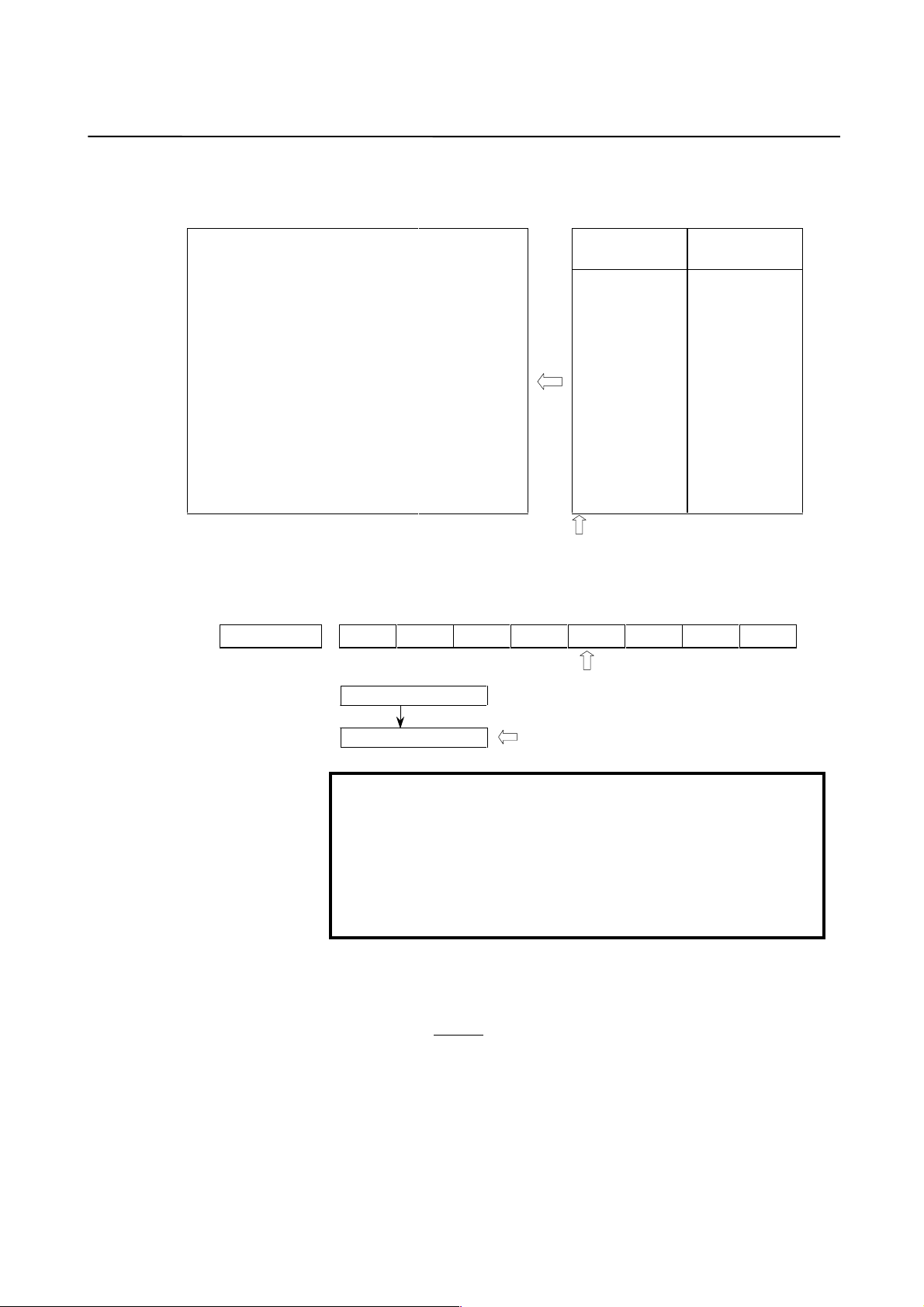
(5) Reference position return when a serial type separate detector is used as
an absolute-position detector
When a serial type separate detector is used as an absolute-position
detector, the phase-Z position must be passed once before a reference
position return is performed. Then, turn the CNC off then back on to
allow reference position return.
When reference position return is performed, adjust the deceleration
dog so that the grid-shifted reference position is not too near the
deceleration dog.
Encoder position
Reference position data
of the detector = 0
Position data from
the encoder
Start position of
reference position return
Grid shift amount
Direction of reference
position return
Reference counter
Deceleration dog
To be adjusted so that the grid-shifted reference
position is not too near the deceleration dog.
Reference position not grid-shifted
Grid-shifted reference
position
Reference counter capacity
Machine position
− 28 −
Page 35

B-65150E/04 2. SETTING α SERIES SERVO PARAMETERS
2.1.5 Actions for Invalid Servo Parameter Setting Alarms
(1) Overview
When a setting value is beyond an allowable range, or when an
overflow occurs during internal calculation, an invalid parameter
setting alarm is issued.
This section explains the procedure to output information to identify
the location and the cause of an invalid parameter setting alarm.
(2) Series and editions of applicable servo software
Series 9080/N (14) and subsequent editions (Series 15-B, 16-C, and
18-C)
Series 9090/E (05) and subsequent editions (Series 16i, 18i, and Power
Mate i)
Series 90A0/A (01) and subsequent editions (Series 15i, 16i, 18i, and
Power Mate i)
(3) Invalid parameter setting alarms that can be displayed in parameter error
detail display
Invalid parameter setting alarms detected by the servo software can be
displayed. Alarms detected by the system software cannot be display ed
here.
To check whether an alarm is detected by the serv o software, check the
following:
(4) Method
#7 #6 #5 #4 #3 #2 #1 #0
Alarm 4 on the servo
screen
1: Alarm detected by the servo software (Detail display is enabled.)
0: Alarm detected by the system software (Detail display is not
enabled.)
When an invalid parameter setting alarm detected by the serv o software
is issued, analyze the cause of the alarm by following the procedure
explained below.
* When more than one alarm is issued, one of the causes of these
alarms is displayed. Analyze the alarms one by one.
Procedure for displaying detail information about an invalid parameter
setting alarm
(For the Series 15i)
On the servo alarm screen, an item indicating param eter error details is
located in the lower left side. Check the number indicated here.
(For the Series 16i, 18i, 21i, and Power Mate i)
On the diagnosis screen, search for No. 352. Check the number written
in No. 352.
PRM
− 29 −
Page 36

2. SETTING α SERIES SERVO PARAMETERS B-65150E/04
(For the Series 15-B)
Check the value in No. 1023 for the axis where a parameter error
occurred. According to the value, set a parameter as follows:
Axis for which an odd value is set in parameter No. 1023:
No. 1726 = 20480
Axis for which an even value is set in parameter No. 1023:
No. 1726 = 22528
Then, open the contents-of-memory screen, and check the data at the
address shown below. Check the 4-digit hexadecimal value.
[When the system is not a multiaxis system]
Axis for which 1 is set in No. 1023: > 908001C0
Axis for which 2 is set in No. 1023: > 908001C2
Axis for which 3 is set in No. 1023: > 90A001C0
Axis for which 4 is set in No. 1023: > 90A001C2
Axis for which 5 is set in No. 1023: > 43C801C0
Axis for which 6 is set in No. 1023: > 43C801C2
Axis for which 7 is set in No. 1023: > 43CA01C0
Axis for which 8 is set in No. 1023: > 43CA01C2
[When the system is a multiaxis system]
Axis for which 1 is set in No. 1023: > A9C801C0
Axis for which 2 is set in No. 1023: > A9C801C2
Axis for which 3 is set in No. 1023: > A9CA01C0
Axis for which 4 is set in No. 1023: > A9CA01C2
Axis for which 5 is set in No. 1023: > AAC801C0
Axis for which 6 is set in No. 1023: > AAC801C2
Axis for which 7 is set in No. 1023: > AACA01C0
Axis for which 8 is set in No. 1023: > AACA01C2
Axis for which 9 is set in No. 1023: > ABC801C0
Axis for which 10 is set in No. 1023: > ABC801C2
Axis for which 11 is set in No. 1023: > ABCA01C0
Axis for which 12 is set in No. 1023: > ABCA01C2
Axis for which 13 is set in No. 1023: > ACC801C0
Axis for which 14 is set in No. 1023: > ACC801C2
Axis for which 15 is set in No. 1023: > ACCA01C0
Axis for which 16 is set in No. 1023: > ACCA01C2
NOTE
To display these addresses, search for the following
address. (Otherwise, a system alarm is issued.)
For 9-inch CRT display: Address xxxxx180
For 15-inch CRT display: Address xxxxx100
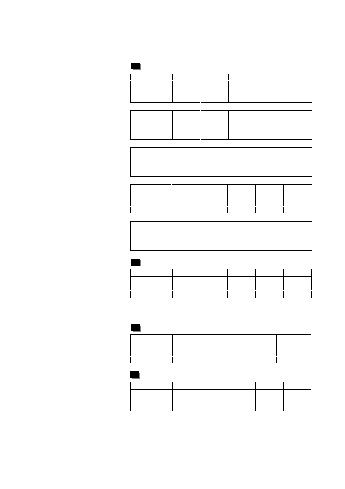
(For the Series 16-C and 18-C)
Set parameters according to the following table:
Setting in No. 1023 1st
axis
No. 8950#0 1 1 1 1 1 1 1 1
No. 8960 1304 1304 1312 1312 1800 1800 1808 1808
No. 2115 20480 22528 20480 22528 20480 22528 20480 22528
2nd
axis
− 30 −
3rd
axis
4th
axis
5th
axis
6th
axis
7th
axis
8th
axis
Page 37

B-65150E/04 2. SETTING α SERIES SERVO PARAMETERS
Then, open the memory screen by pressing an appropriate soft key.
The upper and lower bytes of a parameter error detail number are
displayed in the following addresses:
Axis for which an odd value is set in parameter No. 1023:
> 1C1 (upper byte)
> 1C0 (lower byte)
Axis for which an even value is set in parameter No. 1023:
> 1C3 (upper byte)
> 1C2 (lower byte)
For example, when an invalid parameter setting alarm is caused for the
first axis (set in parameter No. 1023), and 34 is set at address 1C0 and
04 is set at address 1C1 on the memory screen, alarm detail No. is 0434.
NOTE
To display address 1Cx , search for addr ess 199, then
perform page feed by two pages.
However, page feed by more than two pages causes
a system alarm.
Analyzing invalid parameter setting alarms in detail
The detail alarm data basically consists of four digits as shown:
0434
Location where
an alarm was
caused
Cause of the alarm
Upper three digits: Indicate the location where an alarm was caused.
Table 2.1.5 lists the displayed numbers and corresponding
parameter numbers.
* Remark: Basically, the lower three digits in a 4-digit
parameter number in the Series 16 are
indicated.
Lowest digit: Indicates the cause of an alarm.
The displayed numbers and their meanings are explained
below:
1: Because the param eter value is beyond the setting rang e,
a clamped value is used. (This is not an alarm but a
caution. It is not used at present.)
2: The set parameter is invalid. The corresponding
function does not operate.
3: The parameter value is beyond the setting range.
Alternatively, the parameter is not set.
4 to 9: An overflow occurred during internal calculation.
− 31 −
Page 38

2. SETTING α SERIES SERVO PARAMETERS B-65150E/04
NOTE
Basically, 4-digit data is indicated as alarm detail
information. However, 3- or 5-digit data may be
indicated in the following cases:
1 When the diagnosis screen is displayed, three-digit
data is indicated.
Add 0 to the top of the three digits, and read the data
as 4-digit data.
2 When the diagnosis screen is displayed, five-digit
data is indicated.
The d a t a d i s p l a ye d a s A xxx o n the m e m ory screen is
indicated as 10xxx on the diagn osis screen.
Table 2.1.5 Detail analysis of invalid parameter setting alarms
Alarm detail No.
0233 1876 2023 When initialization bit 0 is set to
0243 1891 2024 When initialization bit 0 is set to
0434
0435
0444
0445
0474
0475
0534
0535
0544
0545
0686
0687
0688
0694
0695
0696
0699
0754
0755
Parameter No.
(Series 15)
1855 2043 The internal value of the velocity
1856 2044 The internal value of the velocity
1859 2047 The internal value of the
1865 2053 The internal value of a
1866 2054 The internal value of a
1961 2068 The internal value of the feed-
1962 2069 The internal value of the velocity
1968 2075 The value set in the parameter
Parameter No.
(Series 16, etc.)
Cause Action
1, the number of velocity pulses
exceeds 13100.
1, the number of position pulses
exceeds 13100.
loop integral gain overflowed.
loop proportional gain
overflowed.
observer parameter (POA1)
overflowed.
parameter related to dead zone
compensation overflowed.
parameter related to dead zone
compensation overflowed.
forward coefficient overflowed.
feed-forward coefficient
overflowed.
shown to the left overflowed.
Correct the number of
velocity pulses so that it is
within 13100.
Correct the number of
position pulses so that it is
within 13100.
→ See Supplementary 1.
Decrease the value of the
velocity loop integral gain
parameter.
Use the function for
changing the internal format
of the velocity loop
proportional gain.
→ See Supplementary 2.
Correct the setting to (−1) ×
(desired value)/10.
Decrease the setting to the
extent that the invalid
parameter setting alarm is
not caused.
Decrease the setting to the
extent that the invalid
parameter setting alarm is
not caused.
Use the position gain
expansion function.
→ See Supplementary 3.
Decrease the velocity feedforward coefficient.
This parameter is not used at
present. Set 0.
− 32 −
Page 39

B-65150E/04 2. SETTING α SERIES SERVO PARAMETERS
Alarm detail No.
0764
0765
0783 1971 2078 With the closed-loop linear
0793 1972 2079 With the closed-loop linear
0843 1977 2084 A positive value is not set as the
0853 1978 2085 A positive value is not set as the
0884
0885
0886
0883 1981 2088 For an axis with a serial type
0926
0927
0928
0996 1992 2099 The internal value for N pulse
1123 1705 2112 Although a linear motor is used,
1183 1729 2118 With a closed-loop linear motor,
Parameter No.
(Series 15)
1969 2076 The value set in the parameter
1981 2088 The internal value of the
1985 2092 The internal value of the
Parameter No.
(Series 16, etc.)
Cause Action
shown to the left overflowed.
motor, the conversion coefficient
parameter shown to the left is
not set. (For the Series 9080
only)
motor, the conversion coefficient
parameter shown to the left is
not set. (For the Series 9080
only)
flexible feed gear numerator.
Alternatively, the numerator of
the feed gear is greater than the
denominator.
flexible feed gear denominator.
machine velocity feedback
coefficient overflowed.
separate detector, a value
exceeding 100 is set as the
machine velocity feedback
coefficient.
advanced preview feed-forward
coefficient overflowed.
suppression overflowed.
the AMR conversion coefficient
parameter is not input.
the semi-closed loop error
threshold parameter is not set.
(For the Series 9080 only)
This parameter is not used at
present. Set 0.
Set a value in the parameter
shown to the left.
Set a value in the parameter
shown to the left.
Set a positive value as the
flexible feed gear numerator.
Alternatively, correct the
parameter so that the
numerator of the feed gear is
less than or equal to the
denominator. (For other
than parallel type separate
detectors)
Set a positive value as the
flexible feed gear
denominator.
Decrease the machine
velocity feedback coefficient.
Alternatively, use the
vibration-damping control
function that has an
equivalent effect.
For an axis with a serial type
separate detector, the upper
limit of the machine velocity
feedback coefficient is 100.
Correct the coefficient so
that it does not exceed 100.
Use the position gain
expansion function.
→ See Supplementary 3.
Decrease the value set in the
parameter shown to the left.
Set the AMR conversion
coefficient.
Set the semi-closed loop
error threshold value in the
parameter shown to the left.
1284
1285
1736 2128 When a small value is set as the
number of velocity pulses, the
internal value of a parameter
− 33 −
Decrease the value in the
parameter shown to the left
to the extent that the alarm is
Page 40

2. SETTING α SERIES SERVO PARAMETERS B-65150E/04
Alarm detail No.
1294
1295
1393 1762 2139 The AMR offset value of a linear
1446
1447
1448
1454
1455
1456
1459
8213 1896 1821 A positive value is not set in the
8254
8255
8256
10016 (A016)
10019 (A019)
10033 (A033) 1809 2004 When the ITP cycle is 16 ms,
10043 (A043) 1807#3
10053 (A053) 1960#0 2018#0 When a linear motor is used, the
10062 (A062) 1749#4 2209#4 The amplifier used does not
Parameter No.
(Series 15)
1752 2129 When a large value is set as the
1767 2144 In the cutting feed/rapid traverse
1768 2145 In the cutting feed/rapid traverse
1825 1825 The internal value of the position
1740bit0 2200bit0 The internal value of a
1815#1
1954#2
Parameter No.
(Series 16, etc.)
1815#1
2010#2
Cause Action
related to current control
overflows.
number of velocity pulses, the
internal value of a parameter
related to current control
overflows.
motor exceeds ±45.
FAD function, the feed-forward
coefficient for cutting overflowed.
FAD function, the velocity feedforward coefficient for cutting
overflowed.
reference counter capacity
parameter.
gain overflowed.
parameter related to runaway
detection overflowed.
500 µs is selected as the velocity
control cycle.
2 ms is selected as the velocity
control cycle.
When a linear motor is used, the
closed loop is set. (For series
other than the Series 9080)
scale reverse connection bit is
set.
support the HC alarm prevention
function.
not caused.
When the value set in the
parameter shown to the left
is resolved to the form a ×
256 + b, set a smaller value
in a again.
Correct the parameter
shown to the left so that it is
within ±45.
Use the position gain
expansion function.
→ See Supplementary 3.
Decrease the velocity feedforward coefficient.
Set a positive value in the
parameter shown to the left.
Use the position gain
expansion function.
→ See Supplementary 3.
Do not use the runaway
detection function. (Set bit 0
to 1.)
Correct the parameter
related to interrupt cycle
setting shown to the left.
The closed loop cannot be
set when the linear motor is
used.
When the linear motor is
used, the scale reverse
connection bit cannot be
used.
When you use the current
amplifier continuously, set
the function bit shown to the
left to 0.
When using the HC alarm
prevention function, use an
appropriate amplifier that
supports the function.
− 34 −
Page 41

B-65150E/04 2. SETTING α SERIES SERVO PARAMETERS
Supplementary 1: Setting the number of position pulses
For a separate detector with a fine resolution, the number of position
feedback pulses may exceed 13100 even when initialization bit 0 is set
to 1. In such cases, use the position feedback pulse conversion
coefficient.
Suppose:
Number of position feedback pulses = A × B
Select B so that A is within 32767. Then, set the following:
A: Number of position feedback pulses set in the parameter
(less than or equal to 32767)
B: Conversion coefficient for the number of position feedback
pulses
2628
2185
−
−
Conversion coefficient for the number of position feedback pulses
NOTE
This function is available only with the Series 90A0/N
(14) and subsequent editions.
When the servo software series/edition used does not support this
function, make modifications listed below to prev ent invalid param eter
setting alarms.
E in the table satisfies the following:
Current number of position pulses/E < 13100
Parameter No.
Series
0-C
8x00#0 1804#0 2000#0 1000#0 1
8x23 1876 2023 1023 (Value to be set originally)/10/E
8x24 1891 2024 1024 (Value to be set originally)/10/E
8x43 1855 2043 1043 (Value to be set originally)/E
8x44 1856 2044 1044 (Value to be set originally)/E
8x47 1859 2047 1047 (Value to be set originally)*E
8x53 1865 2053 1053 (Value to be set originally)*E
8x54 1866 2054 1054 (Value to be set originally)/E
8x56 1868 2056 1056 For series supporting HRV control(*): Leave the setting
8x57 1869 2057 1057 For series supporting HRV control(*): Leave the setting
8x59 1871 2059 1059 (Value to be set originally)*E
8x74 1967 2074 1074 For series supporting HRV control: Leave the setting
Series15Series
16, etc.
Power
Mate-E
unchanged.
For series not supporting HRV control: (Value to be set
originally)/E
unchanged.
For series not supporting HRV control: (Value to be set
originally)/E
unchanged.
For series not supporting HRV control: (Remainder of the
value to be set originally/4096)/E + (quotient of the v alue to
be set originally/4096) × 4096
Parameter modification method
− 35 −
Page 42

2. SETTING α SERIES SERVO PARAMETERS B-65150E/04
Parameter No.
Series
0-C
8x76 1969 2076 1076 (Value to be set originally)/E
− 1736 2128 − (Value to be set originally)/E
− 1752 2129 − (Quotient of the value to be set originally/256) × E × 256 +
Series15Series
16, etc.
Power
Mate-E
(remainder of the value to be set originally/256)
Parameter modification method
* The series supporting HRV control includes the Series 9065, 9066,
9080, 9081, 9090, and 90A0.
Supplementary 2: Function for changing the internal format of the velocity loop
proportional gain
An overflow may occur in the velocity loop proportional gain during
internal calculation by the servo software. This can be avoided by
setting the parameter shown below.
(This parameter can be used with the Series 9080/U (21) and
subsequent editions, Series 9090/L (12) and subsequent editions, and
Series 90A0/D (04) and subsequent editions.)
#7 #6 #5 #4 #3 #2 #1 #0
1740
2200
−
−
P2EX (#6) 1: Changes the internal format of the velocity loop proportional gain
0: Uses the standard internal format for the velocity loop proportional
P2EX
to prevent an overflow.
gain.
Supplementary 3: Preventing an overflow in the feed-forward coefficient
An overflow in the feed-forward coefficient may be able to be
prevented by using the position gain setting range expansion function.
(For series other than the Series 0-C)
#7 #6 #5 #4 #3 #2 #1 #0
1804
2000 1000
−
PEX (#4) 1: Enables the position gain setting range expansion function.
0: Disables the position gain setting range expansion function.
The Series 90A0/I (09) edition employs an internal calculation
algorithm that tends to cause less overflows in the feed-forward
coefficient. Before trying the above function, the user of the Series
90A0 should check whether an overflow can be prevented by updating
the software to edition I or subsequent edition.
PEX
− 36 −
Page 43

B-65150E/04 2. SETTING α SERIES SERVO PARAMETERS
Supplementary 4: Preventing an overflow in the position gain
An overflow in the feed-forward coefficient may be able to be
prevented by using the position gain setting range expansion function.
(For series other than the Series 0-C and 15-A)
#7 #6 #5 #4 #3 #2 #1 #0
1804
2000 1000
−
PEX (#4) Position gain setting range expansion function
1: Enables the position gain setting range expansion function.
0: Disables the position gain setting range expansion function.
The setting of the number of position pulses need not be changed.
For the Series 0-C and 15-A, a different method is used to set the
position gain setting range expansion function.
#7 #6 #5 #4 #3 #2 #1 #0
1955 8X11 PEX
− −
PEX (#5) Position gain setting range expansion function
1: Enables the position gain setting range expansion function.
0: Disables the position gain setting range expansion function.
PEX
When setting this function bit to 1, increase the value set as the number
of position pulses by a factor of 8.
#7 #6 #5 #4 #3 #2 #1 #0
1891 8X24 Number of position feedback pulses
− −
If a position gain ov erflow still occurs ev en after the abov e setting s are
made, change CMR.
When CMR is multiplied by A (integer), the flexible feed gear setting
must also be multiplied by A. Since this m eans that the detection unit is
reduced by a factor of A, the parameters that must be set in detection
units must all be multiplied by A.
Appendix C lists the parameters that are to be set in detection units.
(5) When the NC used does not support parameter error detail display
When using an NC that cannot display parameter error detail
information, check for the problems listed in Table 2.1.5 one by one.
(Determine an invalid parameter by, for example, setting each
parameter to 0 to check whether the alarm disappears.)
− 37 −
Page 44

2. SETTING α SERIES SERVO PARAMETERS B-65150E/04
(6) Invalid parameter setting alarm caused by setting an invalid motor number
The table given below lists the valid motor numbers for each series.
If a number beyond the indicated range is set, an invalid parameter
setting alarm is issued.
(In this case, bit 4 of alarm 4 on the servo screen is not set to 1.)
Servo software series/edition Motor No.
Series 9041/A (01) and subsequent editions 3 to 89
Series 9046/A (01)
Series 9046/B (02) and subsequent editions
Series 9046/G (07) and subsequent editions
Series 9060/K (11) and subsequent editions
Series 9060/M (13) and subsequent editions
Series 9060/W (23)
Series 9060/X (23), Y (24)
Series 9064/E (05)
Series 9064/F (06) and subsequent editions
Series 9064/I (09) and subsequent editions
Series 9065/A (01) and subsequent editions 3 to 89
Series 9066/A (01)
Series 9066/B (02)
Series 9066/C (03) and subsequent editions
Series 9066/I (09) and subsequent editions
Series 9066/K (11) and subsequent editions
Series 9070/C (03) and subsequent editions
Series 9070/H (08)
Series 9070/I (09) and subsequent editions
Series 9080/A (01) and subsequent editions
Series 9080/K (11) and subsequent editions
Series 9080/Y (25)
Series 9081/C (03) and subsequent editions
Series 9081/E (05) and subsequent editions
Series 9090/A (01) and subsequent editions
Series 9090/D (04) and subsequent editions
Series 9090/L (12) and subsequent editions
Series 90A0/A (01) and subsequent editions
Series 90A0/D (04) and subsequent editions
Series 90A0/K (11) and subsequent editions
15 to 89
3 to 89
1 to 89
15 to 89
3 to 89
1 to 89
1 to 93
3 to 89
1 to 89
1 to 93
3 to 89
1 to 89
1 to 93
1 to 108
1 to 112
3 to 89
1 to 89
1 to 93
1 to 93
1 to 108
1 to 112
1 to 93
1 to 108
1 to 93
1 to 108
1 to 110
1 to 108
1 to 110
1 to 112
− 38 −
Page 45

B-65150E/04 3. α SERIES PARAMETER ADJUSTMENT
3 α SERIES PARAMETER ADJUSTMENT
− 39 −
Page 46

3. α SERIES PARAMETER ADJUSTMENT B-65150E/04
3.1 SERVO ADJUSTMENT SCREEN
Display the servo adjustment screen, and check the position error,
actual current, and actual speed on the screen.
Using the keys on the NC, enter values according to the procedure
explained below.
(The Power Mate DPL/MDI does not provide the servo adjustment
function.)
Series 0-C
Press the key several times to display the servo setting screen.
Then press the page keys to display the servo
screen.
If the servo setting screen does not appear, set the following parameter,
then switch the NC off and on again.
#7 #6 #5 #4 #3 #2 #1 #0
0389 SVS
SVS (#0) 0: Displays the servo screen.
PARA
PAGE
PAGE
Series 15-A, B, and 15i
Series 16, 18, 20, and 21
3111 SVS
SVS (#0) 1: Displays the servo screen.
Press the key several times to display the servo setting
SERVICE
screen. Then press the key to display the servo adjustment
screen.
SYSTEM
→ [SYSTEM] → [ ] → [SV-PRM] → [SV-TUN]
If the servo screen does not appear, set the following parameter, then
switch the NC off and on again.
#7 #6 #5 #4 #3 #2 #1 #0
<1>
<2>
<3>
<4>
<5>
<6>
<7>
<8>
<9>
<10>
<11>
<12>
<13>
<14>
<15>
<16>
<17>
<18>
− 40 −
Fig. 3.1 (a) Diagnosis screen
Page 47

B-65150E/04 3. α SERIES PARAMETER ADJUSTMENT
>
<9>
<10>
<11>
<12>
<13>
<2>
<5>
<6>
<8>
<7>
<20
<21>
<22>
Fig. 3.1 (b) Diagnosis screen
<14>
<15>
<16>
<17>
<18>
<9>
<10>
<11>
<12>
<13>
Fig. 3.1 (c) Series 15i servo adjustment screen
<19>
<20>
<21>
<22>
Fig. 3.1 (d) Series 15i servo diagnosis screen
− 41 −
Page 48

3. α SERIES PARAMETER ADJUSTMENT B-65150E/04
The items on the servo adjustment screen correspond to the following
parameter numbers:
Table 3.1 Correspondence between the servo adjustment screen and diagnosis screen, and parameters
Series 0-C
<1> Function bit
<2> Loop gain
<3> Tuning start bit
<4> Setting period
<5> Velocity loop integral gain
<6> Velocity loop proportional gain
<7> TCMD filter
<9> Alarm 1 diagnostic
<10> Alarm 2
<11> Alarm 3
<12> Alarm 4
<13> Alarm 5
<19> Alarm 6
<20> Alarm 7
<21> Alarm 8
<22> Alarm 9
<14> Loop gain or actual loop gain The actual servo loop gain is displayed. Not supported
<16> Actual current (%)
<17> Actual current (A)
<18> Actual speed (rpm)
No. 8X03
No. 0517
Not used at present
Not used at present
No. 8X43
No. 8X44
No. 8X67
No. 8X21 No. 1875 No. 2021<8> Velocity loop gain
The relationship with the load inertia ratio (LDINT) is as
follows:
Velocity gain = (1 + LDINT/256)*100(%)
Nos. 720 to 723
730 to 733
760 to 763
770 to 773
__________
__________
__________
__________
__________
Nos. 800 to 803 No. 3000 No. 300 No. 3040<15> Position error diagnostic
Position error = feedrate/(least input increment × 60 × loop gain × 0.01)
Indicates the percentage (%) of the current value to the
continuous rated current.
Indicates the current value.
Indicates the actual speed.
Series 15-A, B,
15i
No. 1808
No. 1825
No. 1855
No. 1856
No. 1857
Nos. 3014 + 20(X - 1)
3015 + 20(X - 1)
3016 + 20(X - 1)
3017 + 20(X - 1)
__________
__________
__________
__________
__________
(mm/min) (mm)
Series 16, 18,
20, 21
No. 2003
No. 1825
No. 2043
No. 2044
No. 2067
No. 200
201
202
203
204
__________
__________
__________
__________
PowerMate-E
No. 1003
No. 0209
No. 1043
No. 1044
No. 1067
Not supported
No. 2711
2710
2713
2712
2714
__________
__________
__________
__________
Not supported
− 42 −
Page 49

B-65150E/04 3. α SERIES PARAMETER ADJUSTMENT
3.2 ACTIONS FOR ALARMS
If a servo alarm is issued, detail alarm information is displayed on the
diagnosis screen (Figs. 3.1 (b) and (d)). Based on this information,
check the cause of the servo alarm and take appropriate action. For
alarms with no action number, refer to relevant manuals such as the
maintenance manual on the amplifier.
Table 3.2 Alarm bit names
#7 #6 #5 #4 #3 #2 #1 #0
Alarm 1 OVL LVA OVC HCA HVA DCA FBA OFA
Alarm 2 ALD EXP
Alarm 3 CS A BLA PHA RCA BZA CKA SPH
Alarm 4 DTE CRC S TB PRM
Alarm 5 OF S MCC LDM PMS FAN DAL ABF
Alarm 6 SFA
Alarm 7 OHA LDA BLA PHA CMA BZA PMA SPH
Alarm 8 DTE CRC STB SPD
Alarm 9 FSD SVE IDW NCE IFE
NOTE) The blank fields do not contain any alarm code.
(1) Alarms related to the amplifier and motor
These alarms are identified from alarms 1, 2, and 5.
(1-1) Type A interface
Alarm 1 Alarm 5 Alarm 2
OVL LVA OVC HCA HVA DCA FBA MCC FAN ALD EXP
1
1
1
1
1
100
110
1
CAUTION
For alarms with no action number indicated, refer to
the maintenance manual on the amplifier.
Description Action
Overcurrent alarm
Excessive voltage alarm
Excessive regenerative
discharge alarm
MCC fusing, precharge
Alarm indicating insufficient
power voltage
Amplifier overheat
Motor overheat
OVC alarm
1
2
2
3
− 43 −
Page 50

3. α SERIES PARAMETER ADJUSTMENT B-65150E/04
(1-2) Type B interface
Alarm 1 Alarm 5 Alarm 2
OVL LVA OVC HCA HVA DCA FBA MCC FAN ALD EXP
1
1
1
1 Excessive voltage alarm
1 Excessive regenerative
1
1
1
1
1
1
1 MCC fusing, precharge
00
01
01
00
10
01
11
00
10
100
101
Description Action
Overcurrent alarm (PSM)
Overcurrent alarm (SVM)
Overcurrent alarm
(software)
discharge alarm
Insufficient power voltage
(PSM)
Insufficient DC link voltage
(PSM)
Insufficient control power
voltage (SVM)
Insufficient DC link voltage
(SVM)
Overheat (PSM)
Motor overheat
Fan stopped (PSM)
Fan stopped (SVM)
1
1
2
2
CAUTION
For alarms with no action number indicated, refer to
the maintenance manual on the amplifier.
Action 1: Overcurrent alarms
This type of alarm is issued when an extremely large current flows
through the main circuit.
When an overcurrent alarm is always issued after emergency stop is
released or at the time of moderate acceleration/deceleration, the cause
of the alarm is determined to be an amplifier failure, cable connection
error, line disconnection, or a parameter setting error. First, check that
standard values are set for the following servo parameters. If these
parameter settings are correct, check the amplifier and cable status by
referencing the maintenance manual on the amplifier.
No. 1809 No. 8X04 No. 1852 No. 8X40 No. 1853 No. 8X41
No. 2004 No. 1004 No. 2040 No. 1040 No. 2041 No. 1041
If an overcurrent alarm is issued only when an abrupt
acceleration/deceleration is performed, the operating conditions seem
to be too strict. Increase the acceleration/deceleration time constant,
and see whether the alarm occurs.
− 44 −
Page 51

B-65150E/04 3. α SERIES PARAMETER ADJUSTMENT
CAUTION
When an emergency stop is released with the power
line to the motor disconnected, an overcurrent alarm
(software) may be issued. If this poses a problem, set
the following parameter bit to 1:
Bit 0 of parameter No. 1747 (Series 15) or bit 0 of
parameter No. 2207: Ignores the overcurrent alarm
(software).
Action 2: Overheat alarms
If an overheat alarm is issued after long -time continuous operation, the
alarm can be determined to have been caused by a temperature rise in
the motor or amplifier. Stop operation for a while, and see whether the
alarm occurs. If the alarm still occurs after the power is kept off for
about 10 minutes, the hardware may be defective.
If the alarm is issued intermittently, increase the time constant, or
increase the programmed stop time period to suppress temperature rise.
Action 3: OVC alarms
When an OVC alarm is issued, check that standard values are set for the
following parameters. If the parameters are correct, increase the time
constant or increase the programmed stop time period to suppress
temperature rise.
No. 1877 No. 8X62 No. 1878 No. 8X63 No. 1893 No. 8X65
No. 2062 No. 1062 No. 2063 No. 1063 No. 2065 No. 1065
(2) Alarms related to the pulse coder and separate serial pulse coder
(2-1) Built-in pulse coder
These alarms are identified from alarms 1, 2, 3, and 5. The
meanings of the bits are as follows:
Alarm 3 Alarm 5 1 Alarm 2
CSA BLA PHA RCA BZA CKA SPH LDM PMA FBA ALD EXP
1
1
1
1 000
1 110
1
1
1
1
1
Soft phase alarm
Clock alarm (serial A)
Zero volts in battery
Abnormal speed (serial A)
Count error alarm
(α pulse coder)
Phase alarm
Voltage drop in battery (warning)
Checksum alarm (serial A)
Pulse error alarm
(α pulse coder)
LED abnormality alarm
(α pulse coder)
Description Action
2
1
2
2
1
− 45 −
Page 52

3. α SERIES PARAMETER ADJUSTMENT B-65150E/04
CAUTION
For alarms with no action number i ndicated, the pul se
coder may be defective. Replace the pulse coder.
(2-2) Separate serial detector coder
These alarms are identified from alarm 7. The meanings of the
bits are as follows:
Alarm 7
OHA LDA BLA PHA CMA BZA PMA SPH
1
1
1
1
1
1
1
1
CAUTION
For alarms with no action number indicated, the
detector may be defective. Replace the detector.
Action 1: Battery-related alarms
Check whether the battery is connected. When the power is turned on
for the first time after the battery is connected, a battery zero alarm is
issued. In this case, turn the power off then on again. If the alarm is
issued again, check the battery voltage. If the battery voltage drop
alarm is issued, check the voltage, then replace the battery.
Description Action
Soft phase alarm
Pulse error alarm
(serial rotary)
Zero volts in battery
Count error alarm
(serial rotary)
Phase alarm (serial linear)
Voltage drop in battery
(warning)
LED abnormality alarm
Separate detector overheat
alarm
2
1
2
2
1
Action 2: Alarms that may be issued by noise
When an alarm is issued intermittently or issued after emergency stop
is released, there is a high possibility that the alarm is caused by noise.
Take thorough noise-preventive measures. If the alarm is still issued
continuously after the measures are taken, replace the detector.
− 46 −
Page 53

B-65150E/04 3. α SERIES PARAMETER ADJUSTMENT
(3) Alarms related to serial communication
These alarms are identified from alarms 4 and 8.
Alarm 4 Alarm 8
DTE CRC STB PRM DTE CRC STB SPD
1
1
1
1
1
1
Communication alarm in serial pulse coder
Communication alarm in separate serial pulse coder
Action: Serial communication is not performed correctly. Check
whether cable connection is correct and whether there is a line
disconnection. If CRC or STBB occurs, the alarm may be
caused by noise. Take noise-preventive measures. If the
alarm is always issued after power is turned on, the pulse
coder, the control board of the amplifier (i Series), or the pulse
module (i Series) may be defective.
(4) Disconnection alarms
These alarms are identified from alarms 1, 2, and 6.
Alarm 1 Alarm 2 6
OVL LVA OVC HCA HVA DCA FBA ALD EXP SFA
1110
1000
1001
Description
Description Action
Hardware disconnection
(separate phase A/B
disconnection)
Software disconnection
(closed loop)
Software disconnection
(α pulse coder)
1
2
3
Action 1: This alarm is issued when the separate phase A/B scale is
used. Check whether the phase A/B detector is connected
correctly.
Action 2: This alarm is issued when the change in position feedback
pulses is relatively small for the change in velocity feedback
pulses. Therefore, with the semi-closed loop, this alarm is
not issued. Check whether the separate detector outputs
position feedback pulses correctly. If the detector outputs
pulses correctly, the alarm is determined to have been
caused by the reverse rotation of only the motor at the start
of machine operation because of a large backlash between
the motor position and scale position.
− 47 −
Page 54

3. α SERIES PARAMETER ADJUSTMENT B-65150E/04
#7 #6 #5 #4 #3 #2 #1 #0
No. 1808 No. 8X 03 TGAL
No. 2003 No. 1003
TGAL (#1) 1: The level of detecting the software disconnection alarm is set by
parameter.
No. 1892 No. 8X 64 Software disconnection alarm level
No. 2064 No. 1064
Standard setting 4: Alarm is issued when motor turns 1/8 of a turn.
Increase this value.
Action 3: This alarm is issued when the absolute position data sent
from the built-in pulse coder cannot be synchronized with
the phase data. Turn off the NC, and remove the pulse coder
cable then attach it again. If this alarm is issued again,
replace the pulse coder.
(5) Invalid parameter setting alarm
This alarm is identified from alarm 4.
Alarm 4
DTER CRC STB PRM
If PRM is set to 1, an invalid parameter setting has been detected by the
servo software. Investig ate the cause of the alarm according to Subsec.
2.1.5, "Actions for Invalid Servo Parameter Setting Alarms."
(6) Other alarms
Alarms are identified from alarm 5. The meanings of the bits are as
follows:
Alarm 5
OFS MCC LDM PMS FAN DAL ABF
1
1
Action 1: This alarm is issued when the move directions for the
position detector and velocity detector are opposite to each
other. Check the rotation direction of the separate detector.
If the direction is opposite to the direction in which the
motor turns, take the following action:
Phase A/B detector: Reverse the A and
Serial detector: Reverse the signal direction setting for
Description
Invalid parameter setting detected
1
by servo software
Description Action
Feedback mismatch alarm 1
1
Excessive semi-closed loop error
alarm
Current offset error alarm 3
__
A connections.
the separate detector.
2
− 48 −
Page 55

B-65150E/04 3. α SERIES PARAMETER ADJUSTMENT
#7 #6 #5 #4 #3 #2 #1 #0
No. 1960
No. 2018
−
−
RVRSE
RVRSE (#0) The signal direction for the separate detector is:
0: Not reversed.
1: Reversed.
When there is a large torsion between the motor and separate detector,
this alarm may be issued when an abrupt acceleration/deceleration is
performed. In such a case, change the detection level.
#7 #6 #5 #4 #3 #2 #1 #0
No. 1741
No. 2201
−
−
RNLV
RNLV (#1) Change of the feedback mismatch alarm detection level
1: To be detected at 1000 rpm or more
0: To be detected at 600 rpm or more
Action 2: This alarm is issued when the difference between the motor
position and the position of the separate detector becomes
larger than the excessive semi-closed loop error level.
Check that the dual position feedback conversion
coefficient is set correctly. If the setting is correct, increase
the alarm level. If the alarm is still issued after the level is
changed, check the scale connection direction.
No. 1971
No. 2078
No. 1972
No. 2079
No. 1729
No. 2118
−
−
−
−
Conversion coefficient @\
−
−
Dual position feedback conversion coefficient (numerator)
Dual position feedback conversion coefficient (denominator)
Number of feedback pulses per motor
revolution (detection unit)
1,000,000
Dual position feedback semi-closed loop error level
[Setting] Detection unit. When 0 is set, detection does not take place.
Action 3: The current offset (equivalent to the current value in the
emergency stop state) of the current detector becomes too
large. If the alarm is issued again after the power is turned
on and off, the current detector is determined to be abnormal.
For the i Series, replace the control board of the amplifier.
For series other than the i Series, replace the servo-related
module in the CNC.
− 49 −
Page 56

3. α SERIES PARAMETER ADJUSTMENT B-65150E/04
3.3 PROCEDURES FOR GAIN ADJUSTMENT AND
VIBRATION-DAMPING CONTROL
3.3.1 Gain Adjustment Procedure
Adjusting the position gain and velocity loop g ain to the optim um state
leads to improvements in control performance and disturbance
suppression performance. Therefore, gain adjustment is the item to be
adjusted first in every machine. Setting a higher velocity loop gain is
effective not only in improvement in surface precision and figure
precision in machining at normal speed but also in improvement in
high-speed high-precision machining and high-speed positioning
performance. The extent to which the velocity loop gain can be
increased almost determines the degree of servo adjustment.
Understanding the gain adjustment procedure that aims at the
improvement of the oscillation lim it helps to determ ine the action to be
taken when vibration occurs. Therefore, it is necessary to understand
the gain adjustment procedure thoroughly.
<1> Preparation for gain adjustment 1:
Check that the servo parameters are set to standard values. The
position gain and velocity loop gain are set to levels that do not generate
vibration (normally, the position gain and velocity loop gain are set to
about 3000 and 150%, respectively).
<2> Preparation for gain adjustment 2:
Select the velocity control method. With high-speed high-precision
machines, PI control should be selected. With high-speed positioning
machines such as a punch press, I-P control should be selected.
<3> Preparation for gain adjustment 3:
Set an auxiliary function to increase the vibration limit. First, set the
velocity loop proportional high-speed processing function(*1).
For a machine with low rigidity, however, setting the acceleration
feedback function instead of the velocity loop proportional high-speed
processing function may produce better results. For a large machine that
can easily be vibrated, it is sometimes undesirable that an auxiliary
function is used. Therefore, follow the procedure explained below to
select a suitable auxiliary function.
(Procedure for selecting an auxiliary function)
First, set the velocity loop proportional high-speed processing function,
and performs steps up to step <6>, "Determining the velocity loop gain
oscillation limit." If the velocity loop gain cannot attain 300%, set the
acceleration feedback function, and perform step <6> again. If a better
result is obtained than with the velocity loop proportional high-speed
processing function, this procedure terminates. If the result is worse,
disable the auxiliary function, and perform step <6> again. Select the
settings with which the highest velocity loop gain is obtained.
− 50 −
Page 57

B-65150E/04 3. α SERIES PARAMETER ADJUSTMENT
*1 The velocity loop proportional high-speed processing function
restricts the use of auxiliary functions that suppress vibration in
the stop state. If vibration in the stop state poses a problem, select
the acceleration feedback function.
<4> Setting for suppressing vibration in the stop state:
A stop occurs within a backlash, and the load inertia decreases.
Accordingly, the velocity loop can easily oscillate. So, set auxiliary
functions for suppressing vibration in the stop state in advance.
Function for changing the proportional gain in the stop state
(50%, 75%)(*2)
N pulse suppression function(*3)
With the 9080/P and subsequent editions, the cutting feed/rapid traverse
velocity loop gain switch function can be used to decrease the gain
during rapid traverse and in the stop state. If vibration in the stop state
poses a problem, decrease the rapid traverse velocity loop gain to a level
that does not affect the behavior during rapid traverse.
*2 With the 90A0/D and subsequent editions, this function can be
used together with the velocity loop proportional high-speed
processing function.
*3 This function cannot be used with the velocity loop proportional
high-speed processing function.
<5> When using level-up HRV:
When using level-up HRV, set the current control period and adjust the
vibration-damping filter according to Subsec. 3.4.1, "Level-up HRV
Control Adjustment Procedure."
− 51 −
Page 58

3. α SERIES PARAMETER ADJUSTMENT B-65150E/04
<6> Determining the velocity loop gain oscillation limit:
After performing the preparatory steps described previously, determine
the velocity loop oscillation limit. When adjusting the velocity loop gain,
perform rapid traverse with full machine strokes, and observe vibration in
the stop state and during high-speed operation by using TCMD and
VCMD.
When using the cutting feed/rapid traverse velocity loop gain function,
perform cutting feed at the maximum cutting feedrate to determine the
oscillation limit during cutting.
(Determining the limit)
As the loop gain increases, the following phenomena start to appear at a
certain gain. This gain value is determined to be the oscillation limit.
• The machine sounds.
• There is a large variation in position error in the stop state.
• Torque command vibration increases.
For a machine with low rigidity, the auxiliary functions listed below are
sometimes required to suppress vibration. Use these functions as
necessary. For details, see Chapter 4, "Servo Function Details."
TCMD filter (*4) Dual position feedback(*5)
Vibration-damping control(*6) Machine velocity feedback(*7)
As the velocity loop gain, set 70% to 80% of the oscillation limit.
*4 As the filter coefficient, about 1500 to 2000 is set. You may want
to set the cut-off frequency to 100 Hz or less to increase the
velocity loop gain. However, this is not a desirable method
because the frequency band widened by velocity loop gain
adjustment is narrowed by the TCMD filter. Except special cases,
when a value greater than 2000 needs to be set, decrease the
velocity loop gain itself.
*5 Dual position feedback (optional function) can be used with the
closed-loop configuration. Set a time constant of about 10 to 300
ms. A lower time constant improves the command follow-up
accuracy. Adjust the time constant after checking the
acceleration/deceleration waveform and machined surface.
*6 Vibration-damping control can be used with the closed-loop
configuration. The difference in velocity between the motor and
machine is fed back to suppress the influence of the torsion
between the motor and machine.
*7 Machine velocity feedback can be used with the closed-loop
configuration. The velocity on the machine side is fed back to
suppress the influence of the torsion between the motor and
machine.
<7> Determining the position loop gain.
Increase the position loop gain to the degree that low-frequency vibration
is not generated during movement.
*8 For the axes subject to interpolation, the same value is set as the
position gain.
− 52 −
Page 59

B-65150E/04 3. α SERIES PARAMETER ADJUSTMENT
3.3.2 Vibration in the Stop State
Vibration generated only in the stop state is caused by the decreased
load inertia in a backlash. Adjust the auxiliary functions for
suppressing stop-time vibration. Vibration may be generated only in
the stop state also when the position gain is too high.
<1> Is an auxiliary function set to increase the oscillation limit for the velocity loop gain?
Small machine with high rigidity: Velocity loop proportional high-speed processing function (function 1)
Medium to large machine with low rigidity: Acceleration feedback function (function 2)
<2> Is an auxiliary function set to suppress vibration in the stop state?
Function for changing the proportional gain in the stop state (50%, 75%) (function 3)
N pulse suppression function (function 4)
<3> Vibration frequency?
Several tens of hertz or higher Low frequency
<4> Decrease the velocity loop gain. When using the
cutting feed/rapid traverse velocity loop gain switch
function, decrease the velocity loop gain for rapid
traverse.
(Reference: Parameter number s)
For details, see Chapter 4, "Servo Function Details."
Function 1: Velocity loop proportional high-speed processing
#7 #6 #5 #4 #3 #2 #1 #0
No. 1959
No. 2017 No. 1017
−
PK2V25
PK2V25 (#7) 1: Enables the velocity loop proportional high-speed processing
function.
<5> The position gain may be too large for the set
velocity loop gain. (Vibration is sometimes
generated when the load inertia is too high or
when the velocity loop gain is not yet adjusted.)
<6> When the velocity loop gain is not adjusted,
follow the description in Subsec. 3.3.1 to set the
velocity loop gain to 70% of the oscillation limit.
<7> Decrease the position gain.
function
Function 2: Acceleration feedback
No. 1894 No. 8X 66 Acceleration feedback gain
No. 2066 No. 1066
− 53 −
Page 60

3. α SERIES PARAMETER ADJUSTMENT B-65150E/04
Function 3: Function for changing the proportional gain in the stop
state
(1) Series 15i, 15-B, 16, 18, 20, 21, and Power Mate
#7 #6 #5 #4 #3 #2 #1 #0
No. 1958
No. 2016
−
−
K2VC
K2VC (#3) 1: Enables the function for changing the proportional gain in the stop
state. In the stop state: 75%
#7 #6 #5 #4 #3 #2 #1 #0
No. 1747
No. 2207
−
−
PK2D50
PK2D50 (#3) 1: Decreases the proportional gain in the stop state to 50%.
No. 1730
No. 2119
−
−
Stop decision level
(2) Series0-C and 15-A
#7 #6 #5 #4 #3 #2 #1 #0
No. 1953 No. 8X09 K2VC
− −
K2VC (#3) 1: (Enables the function for changing the proportional gain in the
stop state. In the stop state: 75%)
No. 1982 No. 8X 89 Stop decision level
− −
− 54 −
Page 61

B-65150E/04 3. α SERIES PARAMETER ADJUSTMENT
3.3.3 Vibration during Travel
Vibration is generated during travel by various causes. So, a most
appropriate method must be selected after observing the vibration
status carefully.
<1> Is an auxiliary function set to increase the oscillation limit for the velocity loop gain?
Machine with high rigidity: Velocity loop proportional high-speed processing function
Machine with low rigidity: Acceleration feedback function
<2> Vibration frequency?
Several tens of
hertz or higher
About several tens Hertz
with separate detector
Low frequency
Vibration occurs especially
during acceleration/
deceleration.
<3> Velocity loop oscillates. Is an auxiliary
function used to suppress vibration?
TCMD filter (function 1)
<4> Is the standard value set for the current loop
gain?
<5> Decrease the velocity loop gain.
<6> Vibration may be due to machine torsion. Is an
auxiliary function used to suppress vibration?
Dual position feedback (function 2)
Vibration-damping control (function 3)
Machine velocity feedback (function 4)
TCMD filter (function 1)
<7> Decrease the position gain.
Use of I-P control may produce effective results. After
checking for a figure error during high-speed cutting,
decrease the position gain, or set I-P control.
<8> Response to vibration components from
the command side. Decrease the velocity
feed-forward coefficient (200 or less).
<9> Set 16 ms for the fine acceleration/
deceleration function. (Function 5)
<11> The position gain may be too large for the set
velocity loop gain. When the velocity loop
gain is not yet adjusted, follow the description
in Subsec. 3.3.1 to set the velocity loop gain to
70% of the oscillation limit.
<12> For PI control, are effective results produced
by decreasing the velocity loop integral gain by
about 2/3?
<13> Decrease the position gain.
− 55 −
Page 62

3. α SERIES PARAMETER ADJUSTMENT B-65150E/04
(Reference: Parameter number s)
For details, see Chapter 4, "Servo Function Details."
Function 1: TCMD filter
No. 1895 No. 8X 67 TCMD filter coefficient
No. 2067 No. 1067
Function 2: Dual position feedback function
#7 #6 #5 #4 #3 #2 #1 #0
No. 1909(i,B)
No. 1955(A)
No. 2019 No. 1019
No. 8X11 DPFB
DPFB (#7) 1: Enables dual position feedback.
No. 1971 No. 8X 78 Dual position feedback conversion coefficient (numerator)
No. 2078 No. 1078
No. 1972 No. 8X 79 Dual position feedback conversion coefficient (denominator)
No. 2079 No. 1079
No. 1973 No. 8X 80 Prim ary delay time constant of dual position feedback
No. 2080 No. 1080
Function 3: Vibration-damping control
No. 1718
No. 2033
No. 1719
No. 2034
−
−
−
−
Number of position feedback pulses for vibration-damping control function
Gain for vibration-damping control function
Function 4: Machine velocity feedback
#7 #6 #5 #4 #3 #2 #1 #0
No. 1956 No. 8X 12 MSFE
No. 2012 No. 1012
MSFE (#1) 1: Enables machine velocity feedback.
No. 1981 No. 8X 88 Machine velocity feedback gain
No. 2088 No. 1088
No. 1951
No. 2007
Function 5: Fine acceleration/deceleration function
#7 #6 #5 #4 #3 #2 #1 #0
−
−
FAD
FAD (#6) 1: Enables fine acceleration/deceleration.
− 56 −
Page 63

B-65150E/04 3. α SERIES PARAMETER ADJUSTMENT
No. 1702
No. 2109
−
−
3.3.4 Cumulative Feed
When the time from the detection of a position error until the
compensation torque is output is too long, a cumulative feed occurs
during low-speed feed. Im provem ent in gain is required. Howev er, for
a machine with high friction and torsion, a higher g ain cannot be set. In
such a case, a cumulative feed phenomenon may occur.
Fine acceleration/deceleration time constant
<1> Adjust the position gain and velocity loop gain
according to the description in Subsec. 3.3.1.
<2> Set PI control.
<3> To improve torque start, increase the velocity loop
integral gain.
<4> Set the VCMD offset function. (Function 1)
<5> Set the incomplete integral coefficient within the
range 32700 to 32767 (function 2). For axes subject
to interpolation, this coefficient must not be set.
(Reference: Parameter number s)
For details, see Chapter 4, "Servo Function Details."
Function 1: VCMD offset function
#7 #6 #5 #4 #3 #2 #1 #0
No. 1808 No. 8X 03 VOFS
No. 2003 No. 1003
VOFS (#7) 1: Enables the VCMD offset function.
No. 1857 No. 8X 45 Incomplete integral gain
No. 2045 No. 1045
− 57 −
Page 64

3. α SERIES PARAMETER ADJUSTMENT B-65150E/04
3.3.5 Overshoot
When the machine is operated at high speed or with a detection unit of
0.1 µm or less, the problem of overshoots may arises. Select a most
appropriate preventive method depending on the cause of an ov ershoot.
<1> When the velocity loop gain is not yet adjusted,
follow the description in Subsec. 3.3.1 to adjust
the gain. Select PI control.
<2> When advanced preview control is used, adjust
automatic corner deceleration. Also, increase
settings such as the time constant after
interpolation to allow commands for corner and
stop operations to be executed as moderately as
possible.
<3> When feed-forward is used, try to adjust the
velocity feed-forward coefficient.
<4> Where possible, decrease the position gain and
feed-forward coefficient.
<5> If the overshoot in question is for about one or two
pulses, set overshoot compensation
(TYPE-1 or -2). (Function 1)
(Reference: Parameter number s)
For details, see Chapter 4, "Servo Function Details."
Function 1: Overshoot compensation function
#7 #6 #5 #4 #3 #2 #1 #0
No. 1808 No. 8X 03 OVSC
No. 2003 No. 1003
OVSC (#6) 1: Enables the overshoot compensation function.
No. 1970 No. 8X 77 Overshoot prevention counter
No. 2077 No. 1077
No. 1857 No. 8X 45 Incomplete integral coefficient
No. 2045 No. 1045
No. 1742
No. 2202
#7 #6 #5 #4 #3 #2 #1 #0
−
−
OVS1
OVS1 (#3) 2: Enables overshoot compensation TYPE-2.
− 58 −
Page 65

B-65150E/04 3. α SERIES PARAMETER ADJUSTMENT
3.4 ADJUSTING PARAMETERS FOR HIGH SPEED AND HIGH
PRECISION
3.4.1 Level-up HRV Control Adjustment Procedure
(1) Overview
With standard systems of the i Series CNC (Series 15i, 16i, and 18i),
the current control period can be changed from the conventional value
250 µs to 125 µs by employm ent of a high-speed DSP for serv o control.
(This function is optional with Series 21i.) With a reduced current
control period, the response of the current loop increases. As the result,
a high velocity loop gain and high position loop gain can be set stably.
With higher velocity loop
Employment of high-speed servo DSP
Current loop response improvement
Higher velocity loop gain
Cutting figure
improvement
High-speed positioning
Simplified servo
adjustment
and position loop gains, the
response and rigidity of a
servo system can be
improved. This capability
enables cutting figure error
reduction and higher-speed
positioning with machine
tools. Moreover, this
capability simplifies servo
adjustment. Thus, level-up
HRV control can improve
overall servo performance.
Fig. 3.4.1 (a) Achievements of level-up HRV control
After servo system adjustment with level-up HRV control, the
parameters for advanced preview control, AI contour control, and
high-precision contour control on the CNC side need to be adjusted.
For information about adjustment of these parameters, see Subsec.
3.4.3, "Servo Parameter Adjustment Procedure for Achieving High
Speed and High Precision."
− 59 −
Page 66

3. α SERIES PARAMETER ADJUSTMENT B-65150E/04
Conventional control Level-up HRV control
Fig. 3.4.1 (b) Example of effects of level-up HRV control
(R100 mm, 10000 mm/min, without quadrant protrusion compensation)
(2) Series and editions of applicable servo software
Series 90A0/E(05) and subsequent editions (Series 15i, 16i, 18i, and
21i. The 320C543 servo card is required.)
(3) Adjustment procedure outline
Use the procedure below for level-up HRV control setting.
<1> Setting of a current loop period and current loop gain (*1 in Fig.
3.4.1 (c))
The current control period is reduced from the conventional v alue
250 µs to 125 µs. An improvement in current response serves as
the base for performance improvement.
<2> Vibration suppression filter adjustment (*2 in Fig. 3.4.1 (c))
Some machines may resonate at a particular frequency. In such a
case, the use of a vibration suppression filter for removing
vibration of a particular frequency is effective.
<3> Velocity loop gain setting (*3 and *4 in Fig. 3.4.1 (c))
A current response improvement due to current control period
reduction and mechanical resonance removal using a vibration
suppression filter raise the oscillation limit of the velocity loop.
When a velocity loop gain adjustment is made, the use of the
high-speed loop proportional high-speed processing function for
processing a part of the velocity loop at high speed is effective.
When the response of a servo system increases, a figure error
dependent on the specified distribution period of the CNC may
appear. Remove such an error by fine acceleration/deceleration.
By setting a velocity loop gain as high as possible, the entire servo
performance can be increased.
<4> Feed-forward coefficient adjustment (*5 in Fig. 3.4.1 (c))
By advanced preview feed-forward, a servo delay is eliminated,
and a figure error is minimized. Usually, a feed-forward
coefficient of 97% to 99% is used.
<5> Position gain adjustment (*6 in Fig. 3.4.1 (c))
As the response of the velocity loop increases, a higher position
gain can be set. A higher position gain is also useful for error
reduction.
− 60 −
Page 67

B-65150E/04 3. α SERIES PARAMETER ADJUSTMENT
Feedforward(*5)
Command
from the
NC
1) Level-up HRV control No. 2004
2) Vibration suppression
filter
3) Velocity loop
proportional highspeed processing
function
4) Fine acceleration/
deceleration function
5) Advanced preview
feed-forward
6) Position gain No. 1825 No. 1825 8000 to 10000 (Set about 5000 at first.)
Fine
acceleration/
deceleration
(*4)
Item
Position
gain(*6)
Fig. 3.4.1 (c) Level-up HRV control adjustment
Table 3.4.1 Standard parameters for using level-up HRV control
(for machining centers with a relatively high rigidity)
Series 16 Series 15 Setting
No. 1809
No. 2040
No. 2041
No. 2113
No. 2177
No. 2017, B7
No. 2021
No. 2007, B6
No. 2209, B2
No. 2109
No. 2005, B1
No. 2092
No. 2069
No. 1852
No. 1853
No. 1706
No. 2620
No. 1959, B7
No. 1875
No. 1951, B6
No. 1749, B2
No. 1702
No. 1883, B1
No. 1985
No. 1962
+
+
Highspeed
velocity
loop(*3)
Standard parameter
00000011 (current loop: 125 µs)
(Standard value) × 0.8
(Standard value) ×1.6
Center frequency of vibration
30 (NOTE: Vibration suppression filter
adjustment requires a relatively long
time. Without this filter, level-up HRV
control can be achieved to some extent.)
1 (Enables this function.)
Approx. 1500 to 2000 (Servo adjustment
screen velocity gain: 700% to 900%)
1 (Enables fine acceleration/
deceleration.)
1 (The fine acceleration/deceleration
time constant is of linear type.)
16 (Fine acceleration/deceleration time
constant)
1 (Enables feed-forward.)
9700 to 9900 (Advanced preview feedforward coefficient)
Approx. 100 (Velocity feed-forward
coefficient)
Vibration
suppression
filter(*2)
Level-up HRV
control(*1)
Switchable
between cutting
feed and rapid
traverse
The setting of a function marked with in the column of "Switchable
between cutting feed and rapid traverse" in Table 3.4.1 can be switched
between cutting feed and rapid traverse. (See Subsec. 3.4.2, "Cutting
Feed/Rapid Traverse Switchable Function.")
− 61 −
Page 68

3. α SERIES PARAMETER ADJUSTMENT B-65150E/04
(4) Details of adjustment
<1> Current loop period setting and current loop gain setting
According to the settings of "1) Level-up HRV control" in Table
3.4.1, set the parameters for current control. Set th e same period
for the two axes controlled by the same DSP.
With these settings, processing is performed using a current loop
period of 125 µs and a position loop period of 1 ms. The response
of the current loop is improved by a factor of 1.6. In this state,
check the activating sound. If, compared with the past, the
activating sound during a stop increases, change the current loop
gain as follows:
• No. 2040 (Series 16), No. 1852 (Series 15) = 0.6 times the
modified value
• No. 2041 (Series 16), No. 1853 (Series 15) = 0.6 times the
modified value
• No. 2042 (Series 16), No. 1854 (Series 15) = 0
NOTE
Set the same period for two axes controlled by the
same DSP.
<2> Vibration suppression filter adjustment
As shown in Fig. 3.4.1 (d), the vibration suppression filter is a
filter that attenuates a particular frequency component included in
a torque command. If a strong resonance exceeding 200 Hz is
present in the mechanical system, the vibration suppression filter
is useful for setting a high velocity gain by suppressing resonance.
So, when using level-up HRV control, adjust the vibration
suppression filter before "<3> Velocity loop gain setting." If the
resonance frequency is 200 Hz or less, do not use a vibration
suppression filter.
For resonance frequency measurement using servo adjustment
software, see "(5) Method of resonance frequency measurement
using servo adjustment software."
Torque command
Vibration suppression
filter
Fig. 3.4.1 (d) Vibration suppression filter
Level-up HRV
control
− 62 −
Page 69

B-65150E/04 3. α SERIES PARAMETER ADJUSTMENT
(Adjustment procedure)
• Operate the machine at a relatively low feedrate (F1000 to
F10000).
• Increase the velocity loop gain gradually until a slight
vibration sound occurs at feed time. If an excessively large
velocity loop gain is set at this time, vibration of low
frequencies within 200 Hz becomes dominant, disabling the
observation of high-frequency vibration that occurs first. If
vibration of a high frequency cannot be observed, the
vibration suppression filter cannot be used.
• After setting a velocity loop gain that generates a slight
vibration sound, observe the TCMD to measure the
frequency.
• Set the measured frequency in the parameters described
below.
[Parameters for setting the vibration suppression filter]
No. 2113 (Series 16), No. 1706 (Series 15)
Attenuation center frequency (Hz): Set the
resonance frequency of the machine.
No. 2117 (Series 16), No. 2620 (Series 15)
Attenuation bandwidth: 30 (40 when the center
frequency is 600 Hz or more)
Before a vibration
suppression filter is used
Velocity gain: 600%
Fig. 3.4.1 (e) Effect of a vibration suppression filter (torque command waveform)
Resonance frequency:
500 Hz
(× 10 Hz) (× 10 Hz)
After a vibration
suppression filter is used
Velocity gain: 800%
<3> Velocity loop gain setting
Adjust the velocity loop gain according to Subsec. 3.3.1, "Gain
Adjustment Procedure."
[Parameters for velocity loop gain adjustment]
No. 2017 (Series 16), No. 1959 (Series 15), B7:
1 (Enables the velocity loop proportional highspeed processing function.)
Velocity gain (gain on the servo adjustment screen):
Increase the velocity gain gradually starting at
about 400%. The target is about 1000%.
− 63 −
Page 70

3. α SERIES PARAMETER ADJUSTMENT B-65150E/04
<4> Fine acceleration/deceleration function setting
When level-up HRV control is used, a high position loop gain and
a high velocity loop gain are set. So, when a greater
acceleration/deceleration is specified, vibration dependent on the
distribution period may occur. To prevent such vibration, fine
acceleration/deceleration is used. Be sure to set a multiple of 8 as
a fine acceleration/deceleration time constant.
[Parameters for fine acceleration/deceleration setting]
No. 2007 (Series 16), No. 1951 (Series 15), B6:
1 (Enables the fine acceleration/deceleration
function.)
No. 2209 (Series 16), No. 1749 (Series 15), B2:
1 (The fine acceleration/deceleration time
constant is of linear type.)
No. 2109 (Series 16), No. 1702 (Series 15):
16 (Fine acceleration/deceleration time
constant)(*1)
*1 For the parameter to be used with fine
acceleration/deceleration switchable for cutting feed and
rapid traverse, see Subsec. 3.4.2, "Cutting Feed/Rapid
Traverse Switchable Function."
<5> Feed-forward coefficient adjustment
Feed-forward is used to compensate for a servo position loop
delay, and velocity feed-forward is used to compensate for a
velocity loop delay. While checking the amount of radius
reduction by using an arc of R10/F4000 or R100/F10000,
adjust the feed-forward coefficient so that the actual path
matches the command. Set a velocity feed-forward
coefficient of 100. For details of adjustment, see Subsec.
3.4.3, "Servo Parameter Adjustment Procedure for
Achieving High Speed and High Precision."
[Parameters for feed-forward setting]
No. 2005 (Series 16), No. 1883 (Series 15), B1:
1 (Enables the feed-forward function.)
No. 2092 (Series 16), No. 1985 (Series 15):
9700 to 9900 (advanced preview feed-forward
coefficient)
No. 2069 (Series 16), No. 1962 (Series 15):
Approx. 100 (velocity feed-forward coefficient)
− 64 −
Page 71

B-65150E/04 3. α SERIES PARAMETER ADJUSTMENT
<6> Position gain adjustment
A specified feedrate is calculated as follows:
Specified feedrate = (position gain) × (positional
deviation) + (feed-forward)
Therefore, if a deviation occurs between the command and
actual position, a higher position gain makes a strong er error
correction, thus making a figure error smaller. When levelup HRV control is used, the response of the velocity loop is
improved, so that a position gain higher than before can be
set. With a medium-size machining center, a value up to
about 80 to 100 [1/s] can be set. (When a large machine or
closed-loop machine is used, a lower value needs to be set if
the backlash between the motor and machine is large.)
Perform rapid traverse and cutting feed at a maximum
cutting feedrate, and find a position gain limit while
observing the TCMD at the time of acceleration/deceleration.
Then, set a value of about 80% of the limit. A position gain
limit appears where a large swell of about 10 to 30 Hz is
observed in the TCMD waveform.
After determining a position g ain value, readjust the position
feed-forward coefficient of <5> above.
[Parameter for position gain setting]
No. 1825 (Series 16, Series 15): 5000 to 10000
(5) Method of resonance frequency measurement using servo adjustment
software
For machine resonance measurement, use the procedure below. It is
assumed that servo adjustment software of a version of October, 1998
and later is used.
<1> Make a preparation to use servo adjustment software (SD). Set
the type of measurement data in Adjustment 2. (When using a
check board of analog/digital integrated type, set 6 as the number
of data digits. When using a digital check board, set the DIP
switch to 12 (for an odd-numbered axis) or 13 (for an evennumbered axis).
<2> Set bit 7 of the parameter No. 2206 (Series 16) or No. 1746 (Series
15) to 1. Set this bit for both axes controlled by the same DSP.
<3> In this state, a TCMD waveform is output for each current loop
control period.
This means that a torque command for 1 second for 4000 data
items can be acquired when the current control period is 250 µs,
and a torque command for 1 second for 8000 data items can be
acquired when the current control period is 125 µs.
− 65 −
Page 72

3. α SERIES PARAMETER ADJUSTMENT B-65150E/04
found to be 500
<4> For the setting of each channel on the F9 screen of SD, select
TCMD Measurement. For am pere setting, set a maxim um current
value of the amplifier.
<5> In this state, accelerate/decelerate the motor, and obtain a
waveform to check that the correct acceleration/deceleration
waveform is output.
<6> With SD, set the number of data points so that data for 0.1 second
can be acquired.
When the current control period is 250 µs: 400 data items
When the current control period is 125 µs: 800 data items
<7> While moving the motor, obtain data when an unusual sound is
generated.
<8> Ensure that SD displays a waveform for only the first axis or
second axis at a time. (Waveforms for the first axis and second
axis can be displayed or hidden with SHIFT+1, and SHIFT+2.)
In addition, set an appropriate value on the F3 menu for
enlargement so that vibration in a TCMD waveform can be
viewed well.
<9> Here, press CTRL+F to set the frequency analysis mode. The
scale value under a spike multiplied by 10 is the frequency of the
vibration.
<10>Upon completion of adjustment, reset the value of bit 7 of No.
2206 (Series 16) or No. 1746 (Series 15) to 0.
In the TCMD waveform, a
vibration component of 50
}3.4.1 (f) @ ⁄ U g “ Ł Æ
(× 10 Hz)
Fig. 3.4.1 (f) Example of resonance frequency
vibrations per 100 ms exists, so
that the frequency of resonance is
Hz.
− 66 −
Page 73

B-65150E/04 3. α SERIES PARAMETER ADJUSTMENT
3.4.2 Cutting Feed/Rapid Traverse Switchable Function
(1) Overview
For cutting figure improvement, the setting of hig her position loop and
velocity loop gains is useful. In general, however, a higher maximum
feedrate and higher acceleration for acceleration/deceleration are used
in rapid traverse, compared with cutting feed. This means that those
settings that achieve stable operation in cutting feed can cause velocity
loop vibration and position loop hunting in rapid traverse. To avoid
such trouble, a function for parameter switching between cutting feed
and rapid traverse for the functions indicated below is available.
acceleration/
deceleration
time constant
(2) Setting procedure
Feed-
forward
coefficient
Fine
Fig. 3.4.2 Parameters switchable between cutting feed and rapid traverse
+
feed-forward
coefficient
+
Velocity
Velocity
loop gain
+
NOTE
1 The TCMD filter and vibration suppression filter can
be used at the same time by parameter setting.
2 The cutting feed/rapid traverse switchable function
is not usable for the vibration suppression filter.
3 With the Series 15-B, the cutting feed/rapi d traverse
switchable function is not usable.
<1> Velocity loop gain
If acceleration in rapid traverse causes TCMD saturation, the
velocity loop tends to oscillate at the end of acceleration in rapid
traverse. Some machine systems tend to oscillate at a higher
frequency when a higher feedrate is used. In such cases, gain
switching between cutting feed and rapid traverse is effective.
If the cutting feed/rapid traverse switchable velocity loop gain
function is set, the conventional velocity gain is used for rapid
traverse, and an overridden value is used for cutting feed. Usually ,
an override value of 150% to 200% is set. If vibration occurs only
when the machine stops, use the function for changing the
proportional gain in the stop state. (With Series 90A0, the
function for changing the proportional gain in the stop state and
the velocity loop proportional high-speed processing function can
be used at the same time.)
TCMD
filter
− 67 −
Page 74

3. α SERIES PARAMETER ADJUSTMENT B-65150E/04
[Applicable servo software]
Series 9080/P(16) and subsequent editions
(Series 16-C, 18-C)
Series 16-MC: BOB1/E and subsequent editions
Series 16-TC: B1B1/C and subsequent editions
Series 18-MC: BDB1/C and subsequent editions
Series 18-TC: BEB1/C and subsequent editions
Series 9090/F(06) and subsequent editions
(Series 16i, 18i, 21i, Power Mate i. The 320C52 servo
card is required.)
Series 90A0/A(01) and subsequent editions
(Series 15i, 16i, 18i, 21i. The 320C543 servo card is
required.)
[Function bit]
#7 #6 #5 #4 #3 #2 #1 #0
No. 1742 VGCCR
No. 2202
1: Enables the cutting feed/rapid traverse switchable velocity loop
gain function.
0: Disables the cutting feed/rapid traverse switchable velocity loop
gain function.
Usually
When the cutting
feed/rapid traverse
switchable function
is enabled
Velocity loop gain (LDINT)
No. 2021 (Series 16)
No. 1875 (Series 15)
Cutting feed
Override value for cutting feed (%)
No. 2107 (Series 16)
No. 1700 (Series 15)
Valid data range: 50 to 400
When a velocity loop gain of 200% (LDINT = 256) and a cutting-time
override of 150% are set, the velocity loop gain for cutting feed is 300%
(LDINT = 512).
LDINT is applicable without modification.
No. 2021 (Series 16)
No. 1875 (Series 15)
Rapid traverse
<2> A fine acceleration/deceleration time constant of about 16 is
optimal for fine acceleration/deceleration, position feed-forward,
and velocity feed-forward cutting . I n rapid traverse, how ever, the
setting of a time constant of 32 to 40 ms may be desirable to
reduce a shock at the time of acceleration/deceleration. Note that
the feed-forward coefficient for figure minimization in cutting is
not always the same as the feed-forward coefficient for
minimizing time for high-speed positioning by rapid traverse. In
such a case, use the cutting feed/rapid traverse switchable fine
acceleration/deceleration function.
− 68 −
Page 75

B-65150E/04 3. α SERIES PARAMETER ADJUSTMENT
No. 2069 (
16), No. 1962 (
[Applicable servo software]
Series 9080/J(10) and subsequent editions
(Series 16-C, 18-C): The series/edition of the CNC
software is the same as <1>.
Series 9090/C(03) and subsequent editions
(Series 16i, 18i, 21i, Power Mate i. The 320C52 servo
card is required.)
Series 90A0/A(01) and subsequent editions
(Series 15i, 16i, 18i, 21i. The 320C543 servo card is
required.)
[Function bit]
#7 #6 #5 #4 #3 #2 #1 #0
No. 1742 FADCH
No. 2202
1: Enables the cutting feed/rapid traverse switchable fine
acceleration/deceleration function.
0: Disables the cutting feed/rapid traverse switchable fine
acceleration/deceleration function.
Usually
When the cutting
feed/rapid traverse
switchable function
is enabled
1. FAD time constant
No. 2109 (Series 16), No. 1702 (Series 15)
2. Feed-forward coefficient
No. 2092 (Series 16), No. 1985 (Series 15)
3. Velocity feed-forward coefficient
No. 2069 (Series 16), No. 1962 (Series 15)
Cutting feed
1. FAD time constant
No. 2143 (Series 16), No. 1766 (Series 15)
2. Feed-forward coefficient
No. 2144 (Series 16), No. 1767 (Series 15)
3. Velocity feed-forward coefficient
No. 2145 (Series 16), No. 1768 (Series 15)
<3> TCMD filter
If high-frequency vibration occurs only in rapid traverse, the
TCMD filter may be more useful than the vibration suppression
filter. On the other hand, if the TCMD filter is used in cutting feed
when it is not needed, the oscillation limit of velocity loop gain
decreases due to a filter delay. In such a case, the use of the
TCMD filter only in rapid traverse is effective.
[Applicable servo software]
Series 9080/U(21) and subsequent editions
(Series 16-C, 18-C): The series/edition of the CNC
software is the same as <1>.
Series 90A0/D(04) and subsequent editions
(Series 15i, 16i, 18i, 21i. The 320C543 servo card is
required.)
Rapid traverse
1. FAD time constant
No. 2109 (Series 16), No. 1702 (Series 15)
2. Feed-forward coefficient
No. 2092 (Series 16), No. 1985 (Series 15)
3. Velocity feed-forward coefficient
Series
Series 15)
− 69 −
Page 76

3. α SERIES PARAMETER ADJUSTMENT B-65150E/04
[Parameter]
No. 1779 TCMD filter coefficient in rapid traverse
No. 2156
Usually
When the cutting
feed/rapid traverse
switchable function
is enabled
TCMD filter
No. 2067 (Series 16), No. 1895 (Series 15)
Cutting feed
TCMD filter
No. 2067 (Series 16), No. 1895 (Series 15)
<4> If the cutting feed/rapid traverse velocity gain switch function is
enabled for the current loop 1/2PI function when the cutting
feed/rapid traverse switchable velocity loop gain function is
enabled, the current loop 1/2PI function is automatically turned
off in rapid traverse. Set the rapid traverse enable bit only if the
current loop 1/2PI function needs to be used also for rapid traverse
when the cutting feed/rapid traverse velocity gain switch function
is enabled.
[Applicable servo software]
Series 9080/X(25) and subsequent editions
(Series 16-C, 18-C): The series/edition of the CNC
software is the same as <1>.
Series 90A0/E(05) and subsequent editions
(Series 15i, 16i, 18i, 21i. The 320C543 servo card is
required.)
Rapid traverse
TCMD filter
No. 2156 (Series 16), No. 1779 (Series 15)
[Function bit]
No. 1742 CPIAL
No. 2202
Usually
1/2PI function
enabled also for
rapid traverse
#7 #6 #5 #4 #3 #2 #1 #0
1: Enables the 1/2PI function also for rapid traverse.
0: Disables the 1/2PI function for rapid traverse.
Current loop 1/2PI function enable bit
No. 2203 (Series 16), B2 = 1
No. 1743 (Series 15), B2 = 1
Cutting feed
Enabled for cutting feed at all times
The 1/2PI function is enabled only for
cutting feed if the cutting feed/rapid
traverse velocity loop gain switch
function is enabled.
− 70 −
The 1/2PI function is enabled for
rapid traverse.
No. 2202 (Series 16), B2 = 1
No. 1742 (Series 15), B2 = 1
Rapid traverse
Page 77

B-65150E/04 3. α SERIES PARAMETER ADJUSTMENT
3.4.3 Servo Parameter Adjustment Procedure for Achieving High
Speed and High Precision
(1) Overview
This section describes the procedure for determining the digital servo
parameters used for advanced preview control, high-precision contour
control, and AI nano-contour control, and the parameters for CNC
acceleration and deceleration based on a feedrate difference. This
section assumes that the servo adjustment software SD.EXE (of a
version of November 1997 and later) is used.
(2) Standard settings
Before staring an actual adjustment, set the default parameters
according to Table 3.4.3 (a). With the servo software series (Series
9080, 9090, and 90A0) that allows the application of fine
acceleration/deceleration, fine acceleration/deceleration can be used
instead of linear acceleration/deceleration after interpolation.
However, fine acceleration/deceleration is disabled during highprecision contour control, AI contour control, and AI nano-contour
control. So, be sure to set the parameter for acceleration/deceleration
after interpolation on the CNC side during batch transfer (such as
during RISC use).
− 71 −
Page 78

3. α SERIES PARAMETER ADJUSTMENT B-65150E/04
Table 3.4.3 (a) Standard settings of parameters for high-speed and high-precision machining
Function Series 16 Series 15 Standard setting
Velocity loop PI 2003 B3 1808 B3 1
Feed-forward enable 2005 B1 1883 B1 1
Velocity feedback acquisition 1 ms 2006 B4 1884 B4 1
Advanced preview feed-forward coefficient 2092 1985 9900
Velocity feed-forward coefficient 2069 1962 50
Velocity loop proportional high-speed processing
function(*1)
Fine acceleration/deceleration enable(*2) 2007 B6 1951 B6 1
Linear-type fine acceleration/deceleration 2209 B2 1749 B2 1
Fine acceleration/deceleration time constant(*3) 2109 1702 32 for large machines
2017 B7 1959 B7 1
24 for medium-sized machines or
small machines
*1 When this function is used, high-frequency vibration can occur,
depending on the resonance point of the machine system. In this
case, stop the use of this function. If high-frequency vibration
occur when a high velocity loop gain is set, use the torque
command filter.
*2 Instead of fine acceleration/deceleration, linear
acceleration/deceleration after interpolation on the CNC can be
used. During batch transfer, do not use fine
acceleration/deceleration, but use acceleration/deceleration after
interpolation on the CNC software side.
*3 For rapid traverse, a time constant of about 40 to 64 ms is required
to perform high-speed positioning by fine
acceleration/deceleration plus feed-forward. In this case, use the
cutting feed/rapid traverse switchable fine
acceleration/deceleration function.
(3) Velocity loop gain adjustment
Make a velocity loop gain adjustment according to Subsec. 3.3.1, "Gain
Adjustment Procedure." Use level-up HRV control when it is
applicable.
[Purpose of adjustment]
By setting a high velocity loop gain, the following can be
achieved:
• Servo rigidity improvement
• Servo response improvement
In machining at normal feedrate, a high velocity loop gain
improves surface precision and figure precision as long as
vibration does not occur. A high velocity loop gain improves
high-speed high-precision machining and high-speed positioning
as well.
For setting a high velocity loop gain stably, the velocity loop
proportional high-speed processing function is useful. As
described in an example given later, the level of an adjustment
that can be made for high-speed high-precision machining almost
depends on the maximum allowable velocity loop gain.
− 72 −
Page 79

B-65150E/04 3. α SERIES PARAMETER ADJUSTMENT
(4) Feed-forward coefficient adjustment (using an arc of R10/F4000)
[Purpose of adjustment]
In a conventional position control loop where feed-forward
control is not exercised, a velocity command is output based on
(positional deviation) × (position loop gain). This means that the
machine moves only when there is a difference between the
specification of a command and the machine position. When the
position gain is 30 [1/s], for example, a feedrate of 10 m/min
generates a positional deviation of 5.56 mm. In linear feed, this
positional deviation does not cause a figure error. For an arc or
corner, however, this positional deviation causes a large figure
error.
A function for eliminating such a positional deviation is feedforward. Feed-forward converts a position command from the
CNC to a velocity comm and for velocity com mand compensation.
Feed-forward can reduce a positional deviation (to almost 0,
theoretically). Accordingly, feed-forward can reduce arc and
corner figure errors. However, the servo response is improved, so
that a shock can occur. To prevent a shock from occurring,
acceleration/deceleration before interpolation must be used at the
same time.
[Guideline for adjustment value setting]
Theoretically, a feed-forward coefficient of 100% leads to a
positional deviation of 0, and eliminates figure errors. Actually,
however, there is a delay in velocity loop response. So, a value
slightly less than 100% produces a specified figure. Usually, a
value between 95% to 99% (settings of 9500 to 9900) is optimum .
As the default, use 9800.
First, adjust the feed-forward coefficient while viewing an arc
figure. (Set a velocity feed-forward coefficient of 50% before
starting adjustment.)
[Actual adjustment]
Create a program as indicated below for circular movement by
R10/F4000, and measure the path with SD. G08P1 and G08P0 in
the program are G codes for starting and ending the advanced
preview control mode in Series 16, respectiv ely. For a m ode to be
used, select the corresponding G codes from Table 3.4.3 (b).
G91;
G08P1;
G17G02I-10.F4000.;
I-10.;
I-10.;
G08P0;
G04X3.;
M99;
− 73 −
Page 80

3. α SERIES PARAMETER ADJUSTMENT B-65150E/04
Table 3.4.3 (b) Codes for starting and ending each mode
Start End
FS16, 18, 21 + Advanced preview control G08P1 G08P0
FS16 + High-precision contour control
FS15B + High-precision contour control
FS15i + Fine HPCC
FS16i + AI contour control
FS16i + AI nano-contour control
FS15B + Advanced preview control
FS21i + AI advanced preview control
G05P10000 G05P0
G05.1Q1 G05.1Q0
In Fig. 3.4.3 (a), the feed-forward coefficient is insufficient, resulting
in a radius reduction of about 5 µm. In addition, the v elocity loop g ain
is low, so that swells and quadrant protrusions are observed. By
adjusting the feed-forward coefficient as shown in Fig. 3.4.3 (b), the
arc radius reduction can be reduced to nearly 0.
Swell
Fig. 3.4.3 (a) Feed-forward adjustment
Velocity loop gain: 100%
Advanced preview feed-forward coefficient: 95%
FAD time constant: 24 ms (linear type)
Quadrant
protrusion
Specified
arc
In the figures above, a low v elocity loop g ain is used for measurement.
By using an increased velocity loop gain, swells and quadrant
protrusions can be reduced (Fig. 3.4.3 (c)). Increase the velocity loop
gain to 70% to 80% of the limit. Adjust the feed-forward coefficient
finely, and apply quadrant protrusion compensation (backlash
acceleration/deceleration) to reduce the quadrant protrusions and
improve the roundness (Fig. 3.4.3 (d)).
Fig. 3.4.3 (b) Feed-forward adjustment
Velocity loop gain: 100%
Advanced preview feed-forward coefficient: 98%
FAD time constant: 24 ms (linear type)
− 74 −
Page 81

B-65150E/04 3. α SERIES PARAMETER ADJUSTMENT
Fig. 3.4.3 (c) Effect of velocity loop gain
Velocity loop gain: 200%
Advanced preview feed-forward coefficient: 98%
FAD time constant: 24 ms (linear type)
Fig. 3.4.3 (d) Effect of velocity loop gain
Velocity loop gain: 300%
Advanced preview feed-forward coefficient: 99%
FAD time constant: 24 ms (linear type)
(5) Velocity feed-forward coefficient adjustment (example using a square
figure with 1/4 arcs)
[Purpose of adjustment]
Feed-forward coefficient adjustment can reduce positional
deviation and figure errors. If the response of the velocity loop for
executing a velocity command is low, velocity control cannot be
exercised as specified where the specified acceleration varies to a
large extent, thus causing a figure error. The response of the
velocity loop can be improved by increasing the velocity loop gain
and by adjusting the velocity feed-forward coefficient.
Velocity feed-forward multiplies a specified rate of variation
(acceleration) by an appropriate coefficient for torque command
compensation. In the servo velocity loop (PI control), a
compensation torque occurs only when a difference (velocity
deviation) between a specified velocity and actual velocity
actually occurs. On the other hand, velocity feed-forward
performs torque command compensation according to an
acceleration value specified beforehand. So, a figure error that
occurs due to a velocity loop delay can be reduced.
[Guideline for adjustment value setting]
The formula below is applicable. In actual adjustment, however,
make an adjustment starting with a velocity feed-forward
coefficient of 100.
(Velocity feed-forward coefficient) = 100 ×
− 75 −
(Motor rotor inertia + load inertia)
Motor rotor inertia
Page 82

3. α SERIES PARAMETER ADJUSTMENT B-65150E/04
[Actual adjustment]
Make a velocity feed-forward coefficient adjustment by using a
square figure with four 1/4 arcs of a 5-mm radius. In this
adjustment, disable the velocity clamp function based on an arc
radius. (Disable the function, or in the example below, ensure that
a velocity equal to or greater than F4000 can be specified.)
G91;
G08P1;
5 mmStart, End
5 mm
Fig. 3.4.3 (e) Programmed figure
G01X10.F4000;
G02X5.Y-5.R5.;
G01Y-20.;
G02X-5.Y-5.R5.;
G01X-20.;
G02X-5.Y5.R5.;
G01Y20.;
G02X5.Y5.R5.;
G01X10.;
G08P0;
G04X3.;
M99;
Press the uppercase character P to enable the display of a reference path.
Execute the program and measure an actual path. Then, an actual path
and reference path are drawn simultaneously as shown below.
Actual path
Specified path
Fig. 3.4.3 (f) Specified path and actual path
When advanced preview feed-forward is disabled, a
figure error of hundreds
µ
m occurs as shown in Fig.
3.4.3 (f), and therefore can be viewed even in the XY
mode. However, if advanced preview feed-forward is
enabled for figure error reduction, it is difficult to
evaluate a figure error correctly unless the error is
enlarged.
In such a case, use the figure comparison m ode (contour
mode) for enlarging errors only for display (ctrl O).
In addition, set an error display magnification with F3
(scale change). For Fig. 3.4.3 (g), a display
magnification of 100 is set.
− 76 −
Page 83

B-65150E/04 3. α SERIES PARAMETER ADJUSTMENT
Protrusion and cut due to
a delay on the Y-axis
Protrusion and cut due to a
delay on the X-axis
The figure display is 5 mm wide.
The error is 50 µm in size.
Fig. 3.4.3 (g) Velocity feed-forward adjustment
Velocity loop gain: 100%
Advanced preview feed-forward coefficient: 99%
FAD time constant: 24 ms (linear type)
Velocity feed-forward: 0%
In Fig. 3.4.3 (g), the velocity feed-forward coefficient is not specified,
so that the movement along each axis delays where acceleration
changes to a large extent. As the result, a protrusion occurs at the joint
of a straight line with an arc, and a cut occurs at the joint of an arc with
a straight line. In Fig. 3.4.3 (h), a velocity feed-forward coefficient is
set for the X-axis only. The response of the X-axis has improved, so
that a figure improvement can be seen in the areas where acceleration
changes to a large extent along the X-axis.
In Fig. 3.4.3 (i), excessively large velocity feed-forward coefficients
are specified, so that the protrusions shown in Fig. 3.4.3 (g) have
changed to cuts, and the cuts have changed to protrusions. This means
that optimum velocity feed-forward coefficients exist and they are less
than the values of Fig. 3.4.3 (i). Fig. 3.4.3 (j) shows the result of
adjustment to the optimum values. Fig. 3.4.3 (k) enlarges the errors
only for display.
Fig. 3.4.3 (h) Velocity feed-forward adjustment
Velocity loop gain: 100%
Advanced preview feed-forward coefficient: 99%
FAD time constant: 24 ms (linear type)
Velocity feed-forward: X100%
Fig. 3.4.3 (i) Velocity feed-forward adjustment
Velocity loop gain: 100%
Advanced preview feed-forward coefficient: 99%
FAD time constant: 24 ms (linear type)
Velocity feed-forward: X200%, Y200%
Fig. 3.4.3 (j) Velocity feed-forward adjustment
Velocity loop gain: 100%
Advanced preview feed-forward coefficient: 99%
FAD time constant: 24 ms (linear type)
Velocity feed-forward: X120%, Y180%
− 77 −
Page 84

3. α SERIES PARAMETER ADJUSTMENT B-65150E/04
is 10
µ
m in size.
When the enlarged range is viewed, it is seen that the machine is
vibrating in the arc areas. This vibration is caused by a low velocity
loop gain. To reduce this vibration, two methods are available. One
method increases the velocity loop gain. (This method cannot be used
when the velocity loop gain has already been increased to the
oscillation limit.) The other method decreases the feedrate in the arc
areas with the arc radius based feedrate clamp function as described in
Subsec. 3.4.3 (6).
Machine vibration
caused by insufficient
velocity control
response is observed.
The figure display is 5 mm wide.
The error
Fig. 3.4.3 (k) Velocity feed-forward adjustment
Swells in the arc areas can be reduced by increasing the velocity loop
gain (Fig. 3.4.3 (l)). However, figure errors that occur at the joints of
straight lines and arcs cannot be fully eliminated. Swells can be
additionally reduced by fine adjustment of the velocity feed-forward
coefficient or by using the arc radius based feedrate clamp function
described in Subsec. 3.4.3 (6).
Figure errors in
this area cannot
be fully eliminated
by increasing the
velocity loop gain.
Swells can be
reduced by
increasing the
velocity loop gain.
Fig. 3.4.3 (l) Velocity feed-forward adjustment
Velocity loop gain: 300%
Advanced preview feed-forward coefficient: 99%
FAD time constant: 24 ms (linear type)
Velocity feed-forward: X120%, Y180%
− 78 −
Page 85

B-65150E/04 3. α SERIES PARAMETER ADJUSTMENT
(6) Adjustment of the parameters for arc radius based feedrate clamping
[Purpose of adjustment]
As mentioned above, velocity feed-forward coefficient
adjustment can improve a velocity loop response delay, thus
reducing figure errors in areas where specified acceleration
changes to a large extent. However, velocity feed-forward
coefficient adjustment alone cannot fully eliminate figure errors.
Moreover, if the rigidity of a machine itself is low, the machine
may vibrate due to a change in acceleration.
To reduce changes in specified acceleration in areas where
acceleration changes to a large extent, the specified feedrate in the
tangent direction is reduced. In part machining (advanced
preview control), the arc radius based feedrate clamp function
performs this feedrate reduction. By adjusting the parameter of
this function, an acceleration value in the normal direction
allowable with a machine can be found. As detailed below, such
an acceleration value can be used as a guideline for setting the
parameter for feedrate reduction by acceleration in hig h- precision
contour control (small successive blocks).
In the figure at left, let R be the
radius of the arc, and F be the
Feedrate F
feedrate. Then, the acceleration in
the normal direction is F
2
/R. The
arc radius based feedrate clamp
Radius R
Acceleration
in the normal
direction
function specifies R and F as its
parameters to ensure that the
acceleration in the normal direction
at a specified arc does not exceed
the specified value.
For example, suppose that when R = 5 mm and F = 4000 mm/min are
specified as the parameters of the arc radius based feedrate clamp
function, the acceleration in the normal direction at the arc is:
2
F
/R = (4000/60)2/5 = 889 mm/sec
2
When using the high-precision contour control function, set about the
same value as this acceleration as the parameter for feedrate reduction
function based on acceleration in small blocks. In the example above,
if a cutting feedrate of F4000 (mm/min) is set, the time required to
reach this feedrate is calculated as follows:
4000/60/889*1000 = 75 msec
− 79 −
Page 86

3. α SERIES PARAMETER ADJUSTMENT B-65150E/04
When the feedrate at an arc is reduced using the arc radius based
feedrate clamp function, figure precision im proves. Howev er, a long er
machining time is required as a side effect. Fig. 3.4.3 (m) shows a
tangent feedrate and processing time when the arc radius based feedrate
clamp function is not used with the adjustment program used in (5) and
later. Fig. 3.4.3 (m) indicates that the tangent feedrate remains to be
F4000. On the other hand, when feedrate reduction to F3000 at R5 m m
is specified with the arc radius based feedrate clamp function, the
tangent feedrate is reduced to F3000 at corners as shown in Fig. 3.4.3
(n), but the machining time has increased by 200 msec.
Tangent
feedrate
1900 msec
X-axis
position
Fig. 3.4.3 (m) When the arc radius based feedrate
clamp function is not used
[Guideline for adjustment value setting]
Empirically, the values below are adequate. For the parameter
numbers, refer to the parameter manual of each CNC.
High-rigidity small machines: F4000 for R5 (889 mm/sec
Medium-size or small machining centers with a relatively high
rigidity: F3000 for R5 (500 mm/sec
Large machines: F2500 for R5 (347 mm/sec
Large machines with a very high rigidity:
Acceleration of
acceleration/
deceleration before
interpolation
Tangent
feedrate
2100 msec
Fig. 3.4.3 (n) When the arc radius based feedrate clamp
Feedrate reduction to
F3000
function is used
F2000 for R5 (222 mm/sec
2
2
2
2
)
)
)
)
[Actual adjustment]
Fig. 3.4.3 (o) shows the results of setting R5 mm and F3000 with
the arc radius based feedrate clamp function for Fig. 3.4.3 (k). Fig.
3.4.3 (o) indicates that the figure errors at the entries and exits of
the arc areas have been reduced.
− 80 −
Page 87

B-65150E/04 3. α SERIES PARAMETER ADJUSTMENT
The figure errors
at the entries and
exits of each arc
The figure display is 5 mm wide.
The e rro r is 1 0
Fig. 3.4.3 (o) Arc radius based feedrate clamping
µ
m in size.
area have been
reduced.
(7) Adjustment of an allowable feedrate difference of the feedrate difference
based corner deceleration function
[Purpose of adjustment]
In the program shown in Fig. 3.4.3 (p), the feedrate along each
axis changes to a great extent at each block joint. With a highprecision high-speed system, the CNC reads programmed figures
beforehand. If the feedrate along each axis changes at a block
joint, such a system can decrease the feedrate by a parameterspecified allowable feedrate difference to reduce a shock and
figure error at the block joint. Acceleration/deceleration is
performed based on the time constant for
acceleration/deceleration before interpolation. A more reduced
corner feedrate makes a figure error improvement to a greater
extent, but requires a longer machining tim e. Set a reduced corner
feedrate to a highest possible value as long as an allowable figure
error is obtained.
[Guideline for setting]
For the parameter number, refer to the parameter manual of each
CNC.
Small machines with a high rigidity: F400
Medium-size or small machining centers with a relatively high
rigidity: F300
Large machines: F200
− 81 −
Page 88

3. α SERIES PARAMETER ADJUSTMENT B-65150E/04
[Actual adjustment procedure]
Execute the following program, and measure the actual path.
Start and end point
Corner 4
Corner 1
Corner 2
Corner 3
Fig. 3.4.3 (p) Programmed figure
G91;
G08P1;
G01X10.F4000;
G01Y-20.;
G01X-20.;
G01Y20.;
G01X10.;
G08P0;
G04X3.;
M99;
The XY mode (ctrl-X) is used for drawing. To observe an overshoot
along an axis to be stopped, the figure is enlarged in the direction of the
axis to be stopped. Corner 1 and corner 3 in Fig. 3.4.3 (p) are enlarg ed
in the X-axis direction, and corner 2 and corner 4 are enlarged in the
Y-axis direction. In the examples below, corner 1 is displayed using
0.01 mm/div in the X-axis direction and 0.1 mm/div in the Y-axis
direction.
In Fig. 3.4.3 (q) where a reduced corner feedrate of F1000 is set, an
overshoot of 10 µm or more has occurred. In Fig. 3.4.3 (r), however,
the overshoot is reduced to about 3 µm.
If an overshoot cannot be remov ed by setting a reduced corner feedrate
close to 0, the acceleration of acceleration/deceleration before
interpolation may be too large. In such a case, set a longer time for
acceleration/deceleration before interpolation. (In this case, a longer
machining time results.)
Fig. 3.4.3 (s) shows the feedrate along the X- axis and Y-axis (corner 1)
when the corner deceleration function is used.
Overshoot
0.01 mm
Fig. 3.4.3 (q) Reduced corner feedrate F1000 Fig. 3.4.3 (r) Reduced corner feedrate F300
− 82 −
Page 89

B-65150E/04 3. α SERIES PARAMETER ADJUSTMENT
with the
Feedrate along the X-axis
Acceleration/deceleration
Reduced corner feedrate
Acceleration/deceleration
at the acceleration of
acceleration/deceleration
before interpolation
time constant for fine
acceleration/deceleration or
acceleration/deceleration
after interpolation
Feedrate along t he Y-axis
Specified feed rat e
Fig. 3.4.3 (s) Time and feedrate relationship for reduced corner feedrate F1000
− 83 −
Page 90

3. α SERIES PARAMETER ADJUSTMENT B-65150E/04
3.4.4 High-Speed Positioning Adjustment Procedure
(1) Overview
This section describes the adjustment procedure for high-speed
positioning required with a punch press and PC board drilling machine.
(2)
Adjustment procedure
Make a high-speed positioning adjustment while viewing the VCMD
(servo error amount) and TCMD. Set a measurement range as
described below.
• V CMD: Adjust the VCMD magnification, measurement voltage
level (when an analog check board is used), and
measurement range (when the servo adjustment
software is used) to allow viewing to a requested
positioning precision. In the example below, a
requested precision of 10 µm is assumed.
• TCMD: Make an adjustment to view a specified maximum
current value. If an adjustment is made to reduce
positioning time, TCMD saturation may occur. Make
an adjustment so that the TCMD lies within a specified
maximum current.
<1> I-P control setting
Select I-P control for velocity loop control. In general, PI control
reduces start-up time for a command, but requires a longer setting
time, so that PI control is not suitable for high-speed positioning.
On the other hand, I-P control reduces time required to reach a
target position, so that I-P control is generally used for hig h-speed
positioning adjustment.
VCMD
Specified maximum
300 ms
TCMD
Fig. 3.4.4 (a) When PI control is used Fig. 3.4.4 (b) When I-P control is used
− 84 −
270 ms
VCMD
20 µm
TCMD
Page 91

B-65150E/04 3. α SERIES PARAMETER ADJUSTMENT
<2> Set a highest possible velocity loop gain according to Subsec.
3.3.1, "Gain Adjustment Procedure."
VCMD
TCMD
TCMD fluctuation
is eliminated.
Fig. 3.4.4 (c) After velocity loop gain adjustment
<3> Set a switch speed of 1500 (15 rpm) with the position gain switch
function (see Subsec. 4.8.1).
VCMD
270 ms
TCMD
Fig. 3.4.4 (d) Position gain switch function
VCMD
240 ms
TCMD
− 85 −
Page 92

3. α SERIES PARAMETER ADJUSTMENT B-65150E/04
of an undershoot increases.
µ
exceeded.
<4> Set a highest possible position gain. While viewing the VCMD
waveform, make an adjustment so that the overshoot value lies
within a requested precision. After setting a position gain,
perform rapid traverse for a long distance to check that lowfrequency vibration due to an excessively increased position gain
does not occur. If the set position gain is too high, vibration after
an overshoot exceeds a requested precision. An overshoot itself
can be suppressed to some extent by adjustment of <5>.
A large vibration occurs in a
VCMD
20 µm
200 ms
TCMD
return movement. Suppress the
vibration to within 50% of the
requested precision.
When a precision of 10 µm is
requested, adjust the overshoot value
to within 10
Fig. 3.4.4 (e) Adequate position gain Fig. 3.4.4 (f) Excessively high position gain
m.
If the position gain is too high, the
requested precision 10 µm is
<5> Make a fine PK1V adjustment to eliminate an overshoot and
undershoot. If a large value is set for PK1V, a large undershoot
occurs.
VCMD
210 ms
VCMD
20 µm
TCMD
TCMD
When the value of PK1V is
increased, the amount of an
overshoot decreases.
Fig. 3.4.4 (g) After PK1V adjustment Fig. 3.4.4 (h) When the value of PK1V is too large
When the value of PK1V is
increased excessively, the amount
− 86 −
Page 93

B-65150E/04 3. α SERIES PARAMETER ADJUSTMENT
3.4.5 Rapid Traverse Positioning Adjustment Procedure
(1) Overview
The fine acceleration/deceleration function applies a filter to each axis
in the servo software to reduce a shock associated with
acceleration/deceleration. By combining the fine
acceleration/deceleration function with feed-forward, high-speed
positioning can be achieved in rapid traverse. This section describes
rapid traverse positioning adjustment.
(2) High-speed positioning by a combination of fine acceleration/deceleration
and feed-forward
(Rapid traverse positioning when fine acceleration/deceleration is
not used)
A servo loop not performing feed-forward has a delay equivalent to a
position loop gain. The time required for positioning after completion
of distribution from the CNC is four to five times the position gain time
constant (33 ms for 30 [1/s]) (133 to 165 ms for a position gain of 30).
In normal rapid traverse, rapid trav erse linear acceleration/deceleration
(Fig. 3.4.5 (a)) is used, so that acceleration changes to a large extent at
the start and end of acceleration. However, since feed-forward is not
used, acceleration change is made moderate by a position loop gain,
and a shock does not occur.
If a low linear acceleration/deceleration time constant is set for highspeed positioning, and a high position gain and feed-forward are set,
the time required for positioning is reduced, but a shock occurs. I n this
case, a shock can be reduced by setting rapid traverse bell-shaped
acceleration/deceleration (optional function) (Fig. 3.4.5 (b)).
Rapid traverse linear time constant (T1) only
Feedrate
Acceleration change is
large, so a shock tends
to occur. Feed-forward
cannot be applied.
T1
Time
Fig. 3.4.5 (a) Rapid traverse linear
acceleration/deceleration
Rapid traverse bell-shaped
acceleration/deceleration (T1+ T2)
Feedrate
Acceleration change is
reduced.
T1 + T2
Fig. 3.4.5 (b) Rapid traverse bell-shaped
acceleration/deceleration
Time
− 87 −
Page 94

3. α SERIES PARAMETER ADJUSTMENT B-65150E/04
(Rapid traverse positioning when fine acceleration/deceleration is
used)
For further reduction in the time required for rapid traverse positioning,
a delay due to a position gain needs to be minimized. For this purpose,
feed-forward needs to be fully utilized. When feed-forward is applied,
the positional deviation decreases. Accordingly, positional deviation
convergence occurs more rapidly after distribution, thus reducing the
time required for positioning.
If feed-forward close to 100% is applied to normal
acceleration/deceleration (Fig. 3.4.5 (a) and (b)), a mechanical shock
due to acceleration change at the start and end of
acceleration/deceleration, and a torque command vibration during
acceleration/deceleration can pose a problem. To cope with this, the
fine acceleration/deceleration function is available (Fig. 3.4.5 (c) and
(d)).
FAD (Tf ≤ 64 ms) is used.
Feedrate
T1 + Tf
Fig. 3.4.5 (c) Fine acceleration/deceleration (FAD) Fig. 3.4.5 (d) Rapid traverse bell-shaped
Compared with linear
acceleration/deceleration,
acceleration change is
reduced, and a smooth
curve results. The time
required for positioning
can be reduced by feedforward.
Time
Rapid traverse bell-shaped acceleration/deceleration
(T2 > 64 ms) is used as well.
Feedrate
T1 + T2 + Tf
acceleration/deceleration + FAD
If a second time constant
greater than 64 ms is required,
rapid traverse bell-shaped
acceleration/
deceleration is used (optional
function). The curve is made
smooth by inserting lineartype FAD of 8 ms.
Time
Fine acceleration/deceleration increases the time required for
command distribution by a time constant. Howev er, a time reduction in
positioning achieved by feed-forward is greater than this increase, so
the time required for positioning can be reduced in total. Thus,
positioning can be speeded up using fine acceleration/deceleration.
The adjustment procedure is described in (3) below.
(T1 + positioning time based on a position gain)
> (T1 + Tf + positioning time based on feed-forward)
A time constant up to 64 ms can be set for fine
acceleration/deceleration. If a time constant greater than 64 ms is
required, use rapid traverse bell-shaped acceleration/deceleration, and
set 8 ms for linear-type fine acceleration/deceleration (Fig. 3.4.5 (d)).
(3) Adjustment procedure
Make a rapid traverse positioning adjustment while viewing the
VCMD (servo error amount). Adjust the measurement range so that
the time required for position deviation convergence within the inposition width can be seen. At the same time, observe the TCMD to
check that the TCMD is not saturated. Before proceeding to the
adjustment described below, adjust the velocity loop gain according to
Subsec. 3.3.1, "Gain Adjustment Procedure."
− 88 −
Page 95

B-65150E/04 3. α SERIES PARAMETER ADJUSTMENT
The measurement data of Fig. 3.4.5 (e) has been obtained under the
condition below. Fine acceleration/deceleration and feed-forward are
not used.
• Rapid traverse rate: 20000 mm/min
• Rapid traverse time constant: 150 ms
• Position gain: 30/s
• Travel distance: 100 mm
When the in-position width is 20 pulses, a time of about 180 ms is
required from distribution completion to positioning. Reducing this
time can speed up positioning.
Command from
the CNC
Servo delay time of
about 180 ms
Fig. 3.4.5 (e) Measurement of time before adjustment
Positional
deviation
In-position width
<1> Default parameter setting for fine acceleration/deceleration and
feed-forward
Set the parameters according to Table 3.4.5. By setting the default
parameters, the time required for positioning can be much
reduced.
Table 3.4.5 Default parameters for rapid traverse positioning adjustment
Item
Rapid traverse feed-forward
enable
Fine acceleration/deceleration
function enable
Linear-type fine
acceleration/deceleration
Fine acceleration/deceleration
time constant
Feed-forward enable No. 2005, B1 No. 1883, B1 1
Feed-forward coefficient No. 2092(*1) No. 1985(*2) 9700
Velocity feed-forward coefficient No. 2069(*1) No. 1962(*2) 100
Series 16 Series 15 Setting
No. 1800, B3 No. 1800, B3 1
No. 2007, B6 No. 1951, B6 1
No. 2009, B2 No. 1749, B2 1
No. 2109(*1) No. 1702(*2) 40
Default parameter
*1 When using different values for cutting and rapid traverse,
use the cutting feed/rapid traverse switchable fine
acceleration/deceleration function according to Subsec.
3.4.2, "Cutting Feed/Rapid Traverse Switchable Function."
*2 Series 15-B does not support the cutting feed/rapid traverse
switchable function.
− 89 −
Page 96

3. α SERIES PARAMETER ADJUSTMENT B-65150E/04
<2> Velocity feed-forward adjustment
When feed-forward is enabled, the time required for positioning
can be reduced, but a swell may occur due to insufficient velocity
loop response immediately before machining stops. A swell can
be reduced by an increased velocity loop gain, but there is an
upper limit on the velocity loop gain. So, adjust the velocity
feed-forward coefficient to reduce a swell for positioning time
reduction.
The default settings cause a swell immediately before machining
stops (Fig. 3.4.5 (f)). The swell can be reduced by increasing the
velocity feed-forward coefficient (Fig. 3.4.5 (g)).
A swell is
observed
immediately
before
machining stops.
An optimum is
achieved
when the swell
here is
reduced.
Fig. 3.4.5 (f) Before velocity feed-forward
adjustment
FAD: 64 ms
Feed-forward: 98.5%
Velocity feed-forward coefficient: 100%
Fig. 3.4.5 (g) After velocity feed-forward
adjustment
FAD: 64 ms
Feed-forward: 98.5%
Velocity feed-forward coefficient: 250%
− 90 −
Page 97

B-65150E/04 3. α SERIES PARAMETER ADJUSTMENT
<3> Fine adjustment of feed-forward
Reduce the time required for positioning by making a fine
adjustment of the feed-forward coefficient. If the feed-forward
coefficient is not sufficiently large (Fig. 3.4.5 (h)), increase the
feed-forward coefficient by about 0.5%. If the feed-forward
coefficient is too large (Fig. 3.4.5 (i)), decrease the feed-forward
coefficient by about 0.5%.
If the feed-forward
coefficient of the
position loop is too
small, an undershoot
occurs, resulting in a
longer time
.
Fig. 3.4.5 (h) When the feed-forward coefficient is
too small
FAD: 64 ms
Feed-forward: 98%
Velocity feed-forward coefficient: 250%
If an adequate feed-forward coefficient is set, the in-position
width is satisfied nearly at the same as distribution command
completion, and shortest-time positioning is achieved as shown in
Fig. 3.4.5 (j).
If the position feed-forward
coefficient is too large, an
overshoot occurs
immediately before
machining stops. If such
an overshoot is allowed
from the viewpoint of
precision, the time
required for positioning is
reduced.
Fig. 3.4.5 (i) When the feed-forward coefficient
is too high
FAD: 64 ms
Feed-forward: 99%
Velocity feed-forward coefficient: 250%
Optimal
adjustment in
precision and
time
Fig. 3.4.5 (j) When an adequate feed-forward coefficient is set
FAD: 64 ms
Feed-forward: 98.5%
Velocity feed-forward coefficient: 250%
− 91 −
Page 98

4. SERVO FUNCTION DETAILS B-65150E/04
4 SERVO FUNCTION DETAILS
− 92 −
Page 99

B-65150E/04 4. SERVO FUNCTION DETAILS
4.1 LIST OF SERVO FUNCTIONS
9
9
9
9
9
9
9
9
9
Servo software series
Function name
[Servo initialization functions]
Flexible feed gear
Parameter invalid alarm detail output
Position gain setting range expansion function
[Servo functions]
HRV control
OVC alarm (type 2)
Level-up HRV
250 µs acceleration feedback
Velocity loop high cycle management function (IP)
Velocity loop high cycle management function (PI)
Velocity loop proportional, support for tandem
Function for changing the proportional gain in the stop
state
Improvement of the function for changing the
proportional gain in the stop state
Addition of the N pulse suppress function
Machine speed feedback function
Machine speed feedback function (normalized)
Observer function
Observer function
(addition of the stop-time disable function)
Torque command filter
Torque command filter
(switchable between cutting feed/rapid traverse)
Dual position feedback function
Dual position feedback function
(zero width improvement)
Vibration-damping control function
Notch filter
Vibration suppression filter
Current loop 1/2PI function
Feed-forward function
Advanced preview control
(advanced preview feed-forward)
9
9
0
0
0
0
0
0
0
0
0
0
0
A
9
8
8
7
6
6
6
6
4
4
0
0
1
0
0
6
5
4
0
6
1
AACBAAAACCA
-------N-EA
AACBAAAACCA
----AF-ECCA
----AF-ECCA
----------A
AACBAAAACCA
-------ACCA
-----BGACCA
----------I
-DQ--AFACCA
-------U--D
AACBAAAACCA
AACBAAAACCA
A-N--ADFCCA
AACBAAAACCA
--W--BHACCA
AACBAAAACCA
-------U--D
A-CBAAAACCA
--YIAFJFCCA
------DAACA
- -G- - AAACCA
----------E
-------K-CA
AACBAAAACCA
AAC- - AAACCA
Related
section in
this manual
2.1
2.1.5
Supplement 4
of Subsec.
2.1.5
4.2
4.2
4.3
4.4.1
4.4.2
4.4.2
4.4.2
4.4.3
4.4.3
4.4.4
4.5.1
4.5.1
4.5.2
4.5.2
4.5.3
4.5.3
4.5.4
4.5.4
4.5.5
4.5.6
4.5.6
4.5.7
4.6.1
4.6.2
− 93 −
Page 100

4. SERVO FUNCTION DETAILS B-65150E/04
9
9
9
9
9
9
9
9
9
Servo software series
Function name
Advanced preview control
(RISC based high-precision contour control)
Advanced preview control
(RISC based high-precision contour control) type 2
Backlash acceleration function
Two-stage backlash acceleration function
Two-stage backlash acceleration function
(enabled only for cutting)
Static friction compensation function
Overshoot compensation function
Overshoot compensation function type 2
Position gain switch function
Position gain switch function type 2
High-speed positioning function setting range
expansion
Low-speed integration function
Fine acceleration/deceleration function
Fine acceleration/deceleration function
(switchable between cutting feed/rapid traverse)
Fine acceleration/deceleration function
(linear-type acceleration/deceleration)
Dummy serial feedback function
FSSB dummy function
Brake control
Emergency stop distance reduction function type 1
Emergency stop distance reduction function type 2
Separate detector hardware disconnection stop
distance reduction function
OVC and OVL alarm stop distance reduction function
Abnormal load detection
Abnormal load detection
(switchable between cutting feed/rapid traverse)
Function for obtaining current offsets at ESP
Support for linear motors
Current loop gain quadruple function
Linear motor torque ripple correction
Torque control function type 1
Torque control function type 2
Super-precision machining function
Tandem control function
Tandem control function
(damping compensation function)
9
9
0
0
0
0
0
0
0
0
0
0
0
A
9
8
8
7
6
6
6
6
4
4
0
0
1
0
0
6
5
4
0
6
1
AAC- - AAACCA
-------ACCA
AACBAAAACCA
--Q- AFACCA
------KJECA
AACBAAAACCA
AACBAAAACCA
-------K-CA
-BC- -AAACCA
-------M-EA
-------O-FA
-BC- -AAACCA
-----D-ECCA
-------J-CA
-------K-EA
BDQI AAEACCA
----------C
AACBAAAACCA
ABL - - ACACCA
-------Y-LI
-------N-EA
-------Y--E
- -EEAAAACCA
-----H-G-CA
-------ACCA
-----D-ACCA
-------R--D
-------ECCA
-----E-ECCA
-----H-S-ID
--------C--
--F---AACCA
--Q----ACCA
Related
section in
this manual
4.6.3
4.6.3
4.6.4
4.6.5
4.6.5
4.6.6
4.7
4.7
4.8.1
4.8.1
4.8.1
4.8.2
4.8.3
4.8.3
4.8.3
4.9.1
4.9.1
4.10
4.11.1
4.11.2
4.11.3
4.11.4
4.12
4.12.1
4.13
4.14.1
4.14.1
4.14.2
4.15
4.15
4.16
4.17
4.17.2
− 94 −
 Loading...