

Page 1

GE Fanuc A utomati on
Computer Numerical Control Products
Ser ies 15 / 16 / 18
Operator's Manual (Remote Diagnostic Function)
GFZ-61214E-4/02 February 1997
Page 2

SAFETY PRECAUTIONS
This section describes the safety precautions related to the use of CNC units. It is essential that these precautions
be observed by users to ensure the safe operation of machines equipped with a CNC unit (all descriptions in this
section assume this configuration). Note that some precautions are related only to specific functions, and thus
may not be applicable to certain CNC units.
Users must also observe the safety precautions related to the machine, as described in the relevant manual supplied
by the machine tool builder. Before attempting to operate the machine or create a program to control the operation
of the machine, the operator must become fully familiar with the contents of this manual and relevant manual
supplied by the machine tool builder.
Contents
1. DEFINITION OF WARNING, CAUTION, AND NOTE s–2. . . . . . . . . . . . . . . . . . . . . . . .
2. GENERAL WARNINGS AND CAUTIONS s–3. . . . . . . . . . . . . . . . . . . . . . . . . . . . . . . . .
3. WARNINGS AND CAUTIONS RELATED TO PROGRAMMING s–5. . . . . . . . . . . . . .
4. WARNINGS AND CAUTIONS RELATED TO HANDLING s–7. . . . . . . . . . . . . . . . . . . .
5. WARNINGS RELATED TO DAILY MAINTENANCE s–9. . . . . . . . . . . . . . . . . . . . . . . . .
s–1
Page 3

1
SAFETY PRECAUTIONS
B–61214E–4/02
DEFINITION OF WARNING, CAUTION, AND NOTE
This manual includes safety precautions for protecting the user and preventing damage to the
machine. Precautions are classified into W arning and Caution according to their bearing on safety.
Also, supplementary information is described as a Note. Read the Warning, Caution, and Note
thoroughly before attempting to use the machine.
WARNING
Applied when there is a danger of the user being injured or when there is a damage of both the user
being injured and the equipment being damaged if the approved procedure is not observed.
CAUTION
Applied when there is a danger of the equipment being damaged, if the approved procedure is not
observed.
NOTE
The Note is used to indicate supplementary information other than Warning and Caution.
Read this manual carefully, and store it in a safe place.
s–2
Page 4

B–61214E–4/02
2
SAFETY PRECAUTIONS
GENERAL WARNINGS AND CAUTIONS
WARNING
1.
Never attempt to machine a workpiece without first checking the operation of the machine.
Before starting a production run, ensure that the machine is operating correctly by performing
a trial run using, for example, the single block, feedrate override, or machine lock function or
by operating the machine with neither a tool nor workpiece mounted. Failure to confirm the
correct operation of the machine may result in the machine behaving unexpectedly, possibly
causing damage to the workpiece and/or machine itself, or injury to the user.
2.
Before operating the machine, thoroughly check the entered data.
Operating the machine with incorrectly specified data may result in the machine behaving
unexpectedly , possibly causing damage to the workpiece and/or machine itself, or injury to the
user.
3.
Ensure that the specified feedrate is appropriate for the intended operation. Generally , for each
machine, there is a maximum allowable feedrate. The appropriate feedrate varies with the
intended operation. Refer to the manual provided with the machine to determine the maximum
allowable feedrate. If a machine is run at other than the correct speed, it may behave
unexpectedly , possibly causing damage to the workpiece and/or machine itself, or injury to the
user.
4.
When using a tool compensation function, thoroughly check the direction and amount of
compensation.
Operating the machine with incorrectly specified data may result in the machine behaving
unexpectedly , possibly causing damage to the workpiece and/or machine itself, or injury to the
user.
5.
The parameters for the CNC and PMC are factory–set. Usually , there is not need to change them.
When, however, there is not alternative other than to change a parameter, ensure that you fully
understand the function of the parameter before making any change.
Failure to set a parameter correctly may result in the machine behaving unexpectedly , possibly
causing damage to the workpiece and/or machine itself, or injury to the user.
s–3
Page 5

SAFETY PRECAUTIONS
B–61214E–4/02
CAUTION
1.
Immediately after switching on the power, do not touch any of the keys on the MDI panel until
the position display or alarm screen appears on the CNC unit.
Some of the keys on the MDI panel are dedicated to maintenance or other special operations.
Pressing any of these keys may place the CNC unit in other than its normal state. Starting the
machine in this state may cause it to behave unexpectedly.
2.
The operator’s manual and programming manual supplied with a CNC unit provide an overall
description of the machine’s functions, including any optional functions. Note that the optional
functions will vary from one machine model to another. Therefore, some functions described
in the manuals may not actually be available for a particular model. Check the specification of
the machine if in doubt.
3.
Some functions may have been implemented at the request of the machine–tool builder. When
using such functions, refer to the manual supplied by the machine–tool builder for details of their
use and any related cautions.
NOTE
Programs, parameters, and macro variables are stored in nonvolatile memory in the CNC unit.
Usually , they are retained even if the power is turned off. Such data may be deleted inadvertently,
however, or it may prove necessary to delete all data from nonvolatile memory as part of error
recovery.
To guard against the occurrence of the above, and assure quick restoration of deleted data, backup
all vital data, and keep the backup copy in a safe place.
s–4
Page 6

B–61214E–4/02
3
1.
SAFETY PRECAUTIONS
WARNINGS AND CAUTIONS RELATED TO PROGRAMMING
This section covers the major safety precautions related to programming. Before attempting to
perform programming, read the supplied operator’s manual and programming manual carefully
such that you are fully familiar with their contents.
WARNING
Coordinate system setting
If a coordinate system is established incorrectly, the machine may behave unexpectedly as a
result of the program issuing an otherwise valid move command.
Such an unexpected operation may damage the tool, the machine itself, the workpiece, or cause
injury to the user.
2.
Positioning by nonlinear interpolation
When performing positioning by nonlinear interpolation (positioning by nonlinear movement
between the start and end points), the tool path must be carefully confirmed before performing
programming.
Positioning involves rapid traverse. If the tool collides with the workpiece, it may damage the
tool, the machine itself, the workpiece, or cause injury to the user.
3.
Function involving a rotation axis
When programming polar coordinate interpolation or normal–direction (perpendicular) control,
pay careful attention to the speed of the rotation axis. Incorrect programming may result in the
rotation axis speed becoming excessively high, such that centrifugal force causes the chuck to
lose its grip on the workpiece if the latter is not mounted securely.
Such mishap is likely to damage the tool, the machine itself, the workpiece, or cause injury to
the user.
4.
Inch/metric conversion
Switching between inch and metric inputs does not convert the measurement units of data such
as the workpiece origin offset, parameter, and current position. Before starting the machine,
therefore, determine which measurement units are being used. Attempting to perform an
operation with invalid data specified may damage the tool, the machine itself, the workpiece, or
cause injury to the user.
5.
Constant surface speed control
When an axis subject to constant surface speed control approaches the origin of the workpiece
coordinate system, the spindle speed may become excessively high. Therefore, it is necessary
to specify a maximum allowable speed. Specifying the maximum allowable speed incorrectly
may damage the tool, the machine itself, the workpiece, or cause injury to the user.
s–5
Page 7

SAFETY PRECAUTIONS
W ARNING
6.
Stroke check
After switching on the power, perform a manual reference position return as required. Stroke
check is not possible before manual reference position return is performed. Note that when stroke
check is disabled, an alarm is not issued even if a stroke limit is exceeded, possibly damaging
the tool, the machine itself, the workpiece, or causing injury to the user.
7.
Tool post interference check
A tool post interference check is performed based on the tool data specified during automatic
operation. If the tool specification does not match the tool actually being used, the interference
check cannot be made correctly, possibly damaging the tool or the machine itself, or causing
injury to the user.
After switching on the power, or after selecting a tool post manually, always start automatic
operation and specify the tool number of the tool to be used.
B–61214E–4/02
CAUTION
1.
Absolute/incremental mode
If a program created with absolute values is run in incremental mode, or vice versa, the machine
may behave unexpectedly.
2.
Plane selection
If an incorrect plane is specified for circular interpolation, helical interpolation, or a canned cycle,
the machine may behave unexpectedly . Refer to the descriptions of the respective functions for
details.
3.
Torque limit skip
Before attempting a torque limit skip, apply the torque limit. If a torque limit skip is specified
without the torque limit actually being applied, a move command will be executed without
performing a skip.
4.
Programmable mirror image
Note that programmed operations vary considerably when a programmable mirror image is
enabled.
5.
Compensation function
If a command based on the machine coordinate system or a reference position return command
is issued in compensation function mode, compensation is temporarily canceled, resulting in the
unexpected behavior of the machine.
Before issuing any of the above commands, therefore, always cancel compensation function
mode.
s–6
Page 8

B–61214E–4/02
4
1.
SAFETY PRECAUTIONS
WARNINGS AND CAUTIONS RELATED TO HANDLING
This section presents safety precautions related to the handling of machine tools. Before attempting
to operate your machine, read the supplied operator’s manual and programming manual carefully,
such that you are fully familiar with their contents.
WARNING
Manual operation
When operating the machine manually , determine the current position of the tool and workpiece,
and ensure that the movement axis, direction, and feedrate have been specified correctly.
Incorrect operation of the machine may damage the tool, the machine itself, the workpiece, or
cause injury to the operator.
2.
Manual reference position return
After switching on the power, perform manual reference position return as required. If the
machine is operated without first performing manual reference position return, it may behave
unexpectedly . Stroke check is not possible before manual reference position return is performed.
An unexpected operation of the machine may damage the tool, the machine itself, the workpiece,
or cause injury to the user.
3.
Manual numeric command
When issuing a manual numeric command, determine the current position of the tool and
workpiece, and ensure that the movement axis, direction, and command have been specified
correctly, and that the entered values are valid.
Attempting to operate the machine with an invalid command specified may damage the tool, the
machine itself, the workpiece, or cause injury to the operator.
4.
Manual handle feed
In manual handle feed, rotating the handle with a large scale factor, such as 100, applied causes
the tool and table to move rapidly. Careless handling may damage the tool and/or machine, or
cause injury to the user.
5.
Disabled override
If override is disabled (according to the specification in a macro variable) during threading, rigid
tapping, or other tapping, the speed cannot be predicted, possibly damaging the tool, the machine
itself, the workpiece, or causing injury to the operator.
6.
Origin/preset operation
Basically, never attempt an origin/preset operation when the machine is operating under the
control of a program. Otherwise, the machine may behave unexpectedly , possibly damaging the
tool, the machine itself, the tool, or causing injury to the user.
s–7
Page 9

SAFETY PRECAUTIONS
W ARNING
7.
Workpiece coordinate system shift
Manual intervention, machine lock, or mirror imaging may shift the workpiece coordinate
system. Before attempting to operate the machine under the control of a program, confirm the
coordinate system carefully.
If the machine is operated under the control of a program without making allowances for any shift
in the workpiece coordinate system, the machine may behave unexpectedly , possibly damaging
the tool, the machine itself, the workpiece, or causing injury to the operator.
8.
Software operator’s panel and menu switches
Using the software operator’s panel and menu switches, in combination with the MDI panel, it
is possible to specify operations not supported by the machine operator’s panel, such as mode
change, override value change, and jog feed commands.
Note, however, that if the MDI panel keys are operated inadvertently, the machine may behave
unexpectedly, possibly damaging the tool, the machine itself, the workpiece, or causing injury
to the user.
B–61214E–4/02
CAUTION
1.
Manual intervention
If manual intervention is performed during programmed operation of the machine, the tool path
may vary when the machine is restarted. Before restarting the machine after manual intervention,
therefore, confirm the settings of the manual absolute switches, parameters, and
absolute/incremental command mode.
2.
Feed hold, override, and single block
The feed hold, feedrate override, and single block functions can be disabled using custom macro
system variable #3004. Be careful when operating the machine in this case.
3.
Dry run
Usually , a dry run is used to confirm the operation of the machine. During a dry run, the machine
operates at dry run speed, which differs from the corresponding programmed feedrate. Note that
the dry run speed may sometimes be higher than the programmed feed rate.
4.
Cutter and tool nose radius compensation in MDI mode
Pay careful attention to a tool path specified by a command in MDI mode, because cutter or tool
nose radius compensation is not applied. When a command is entered from the MDI to interrupt
in automatic operation in cutter or tool nose radius compensation mode, pay particular attention
to the tool path when automatic operation is subsequently resumed. Refer to the descriptions of
the corresponding functions for details.
5.
Program editing
If the machine is stopped, after which the machining program is edited (modification, insertion,
or deletion), the machine may behave unexpectedly if machining is resumed under the control
of that program. Basically , do not modify, insert, or delete commands from a machining program
while it is in use.
s–8
Page 10

B–61214E–4/02
5
1.
SAFETY PRECAUTIONS
WARNINGS RELATED TO DAILY MAINTENANCE
WARNING
Memory backup battery replacement
When replacing the memory backup batteries, keep the power to the machine (CNC) turned on,
and apply an emergency stop to the machine. Because this work is performed with the power
on and the cabinet open, only those personnel who have received approved safety and
maintenance training may perform this work.
When replacing the batteries, be careful not to touch the high–voltage circuits (marked
fitted with an insulating cover).
Touching the uncovered high–voltage circuits presents an extremely dangerous electric shock
hazard.
and
NOTE
The CNC uses batteries to preserve the contents of its memory , because it must retain data such as
programs, offsets, and parameters even while external power is not applied.
If the battery voltage drops, a low battery voltage alarm is displayed on the machine operator’s panel
or CR T screen.
When a low battery voltage alarm is displayed, replace the batteries within a week. Otherwise, the
contents of the CNC’s memory will be lost.
Refer to the maintenance section of the operator’s manual or programming manual for details of the
battery replacement procedure.
s–9
Page 11

SAFETY PRECAUTIONS
B–61214E–4/02
W ARNING
2.
Absolute pulse coder battery replacement
When replacing the memory backup batteries, keep the power to the machine (CNC) turned on,
and apply an emergency stop to the machine. Because this work is performed with the power
on and the cabinet open, only those personnel who have received approved safety and
maintenance training may perform this work.
When replacing the batteries, be careful not to touch the high–voltage circuits (marked
fitted with an insulating cover).
Touching the uncovered high–voltage circuits presents an extremely dangerous electric shock
hazard.
NOTE
The absolute pulse coder uses batteries to preserve its absolute position.
If the battery voltage drops, a low battery voltage alarm is displayed on the machine operator’s panel
or CR T screen.
When a low battery voltage alarm is displayed, replace the batteries within a week. Otherwise, the
absolute position data held by the pulse coder will be lost.
Refer to the maintenance section of the operator’s manual or programming manual for details of the
battery replacement procedure.
and
3.
Fuse replacement
For some units, the chapter covering daily maintenance in the operator’s manual or programming
manual describes the fuse replacement procedure.
Before replacing a blown fuse, however, it is necessary to locate and remove the cause of the
blown fuse.
For this reason, only those personnel who have received approved safety and maintenance
training may perform this work.
When replacing a fuse with the cabinet open, be careful not to touch the high–voltage circuits
(marked
Touching an uncovered high–voltage circuit presents an extremely dangerous electric shock
hazard.
and fitted with an insulating cover).
s–10
Page 12

B–61214E–4/02
PREFACE
PREFACE
This manual describes the following products:
Product Name Abbreviation
FANUC Series 15–TA 15–TA
FANUC Series 15–TF 15–TF
FANUC Series 15–TTA 15–TTA
FANUC Series 15–TTF 15–TTF
FANUC Series 15–MA 15–MA
FANUC Series 15–MF 15–MF
FANUC Series 16–TA 16–TA
FANUC Series 16–MA 16–MA
FANUC Series 16–TTA 16–TTA
FANUC Series 16–TB 16–TB
FANUC Series 16–MB 16–MB
FANUC Series 16–TC 16–TC
FANUC Series 16–MC 16–MC
FANUC Series 18–TA 18–TA
FANUC Series 18–MA 18–MA
FANUC Series 18–TTA 18–TTA
FANUC Series 18–TB 18–TB
FANUC Series 18–MB 18–MB
FANUC Series 18–TC 18–TC
FANUC Series 18–MC 18–MC
p–11
Page 13

B–61214E–4/02
Table of Contents
SAFETY PRECAUTIONS s–1. . . . . . . . . . . . . . . . . . . . . . . . . . . . . . . . . . . . . . . . . . . . . . . . . . . . .
PREFACE p–1. . . . . . . . . . . . . . . . . . . . . . . . . . . . . . . . . . . . . . . . . . . . . . . . . . . . . . . . . . . . . . . . . . .
I. SPECIFICATIONS
1. OVERVIEW 3. . . . . . . . . . . . . . . . . . . . . . . . . . . . . . . . . . . . . . . . . . . . . . . . . . . . . . . . . . . . . . . . .
1.1 OUTLINE 4. . . . . . . . . . . . . . . . . . . . . . . . . . . . . . . . . . . . . . . . . . . . . . . . . . . . . . . . . . . . . . . . . . . . . . . .
1.2 CNC Options (Series 15) 6. . . . . . . . . . . . . . . . . . . . . . . . . . . . . . . . . . . . . . . . . . . . . . . . . . . . . . . . . . . . .
1.3 SUPPOR TED PERSONAL COMPUTER MODELS 7. . . . . . . . . . . . . . . . . . . . . . . . . . . . . . . . . . . . . . .
2. WORK DISK CREATION 8. . . . . . . . . . . . . . . . . . . . . . . . . . . . . . . . . . . . . . . . . . . . . . . . . . . . .
2.1 OVER VIEW 9. . . . . . . . . . . . . . . . . . . . . . . . . . . . . . . . . . . . . . . . . . . . . . . . . . . . . . . . . . . . . . . . . . . . . . .
2.2 INST ALL PROCEDURE 10. . . . . . . . . . . . . . . . . . . . . . . . . . . . . . . . . . . . . . . . . . . . . . . . . . . . . . . . . . .
2.3 DEVICE DRIVER DISK 12. . . . . . . . . . . . . . . . . . . . . . . . . . . . . . . . . . . . . . . . . . . . . . . . . . . . . . . . . . . .
2.4 ORIGINAL AND WORK DISKS 13. . . . . . . . . . . . . . . . . . . . . . . . . . . . . . . . . . . . . . . . . . . . . . . . . . . . .
2.5 MODEL–SPECIFIC KEY CODE FILE 14. . . . . . . . . . . . . . . . . . . . . . . . . . . . . . . . . . . . . . . . . . . . . . . .
2.6 PCB DRAWING NUMBER FILE (Series 15) 15. . . . . . . . . . . . . . . . . . . . . . . . . . . . . . . . . . . . . . . . . . .
3. CONNECTION 16. . . . . . . . . . . . . . . . . . . . . . . . . . . . . . . . . . . . . . . . . . . . . . . . . . . . . . . . . . . . .
3.1 CONNECTING MODEM 17. . . . . . . . . . . . . . . . . . . . . . . . . . . . . . . . . . . . . . . . . . . . . . . . . . . . . . . . . . .
3.1.1 Connecting the CNC Machine Tool and Modem 17. . . . . . . . . . . . . . . . . . . . . . . . . . . . . . . . . . . . .
3.1.2 Connecting Personal Computer and Modem 18. . . . . . . . . . . . . . . . . . . . . . . . . . . . . . . . . . . . . . . .
3.2 SETTING COMMUNICATION PARAMETERS 19. . . . . . . . . . . . . . . . . . . . . . . . . . . . . . . . . . . . . . . .
3.2.1 CNC Setting Parameters 19. . . . . . . . . . . . . . . . . . . . . . . . . . . . . . . . . . . . . . . . . . . . . . . . . . . . . . . .
3.2.2 Setting for Personal Computer 20. . . . . . . . . . . . . . . . . . . . . . . . . . . . . . . . . . . . . . . . . . . . . . . . . . .
3.2.3 Setting for Modem 20. . . . . . . . . . . . . . . . . . . . . . . . . . . . . . . . . . . . . . . . . . . . . . . . . . . . . . . . . . . .
3.3 CONNECTING TELEPHONE LINE 21. . . . . . . . . . . . . . . . . . . . . . . . . . . . . . . . . . . . . . . . . . . . . . . . . .
3.3.1 Mode of Modem 21. . . . . . . . . . . . . . . . . . . . . . . . . . . . . . . . . . . . . . . . . . . . . . . . . . . . . . . . . . . . . .
3.3.2 Line Connection 21. . . . . . . . . . . . . . . . . . . . . . . . . . . . . . . . . . . . . . . . . . . . . . . . . . . . . . . . . . . . . .
3.3.3 Termination 22. . . . . . . . . . . . . . . . . . . . . . . . . . . . . . . . . . . . . . . . . . . . . . . . . . . . . . . . . . . . . . . . . .
II. OPERATION
1. FUNCTION OVERVIEW 25. . . . . . . . . . . . . . . . . . . . . . . . . . . . . . . . . . . . . . . . . . . . . . . . . . . . .
1.1 OUTLINE 26. . . . . . . . . . . . . . . . . . . . . . . . . . . . . . . . . . . . . . . . . . . . . . . . . . . . . . . . . . . . . . . . . . . . . . .
1.1.1 Language Selection Screen 26. . . . . . . . . . . . . . . . . . . . . . . . . . . . . . . . . . . . . . . . . . . . . . . . . . . . . .
1.1.2 Wireless Adapter Selection Screen 26. . . . . . . . . . . . . . . . . . . . . . . . . . . . . . . . . . . . . . . . . . . . . . . .
1.1.3 Access Right Confirmation Screen (Series 16/18) 27. . . . . . . . . . . . . . . . . . . . . . . . . . . . . . . . . . . .
1.1.4 Command Selection Screen 27. . . . . . . . . . . . . . . . . . . . . . . . . . . . . . . . . . . . . . . . . . . . . . . . . . . . .
1.1.5 Function Selection Screen 27. . . . . . . . . . . . . . . . . . . . . . . . . . . . . . . . . . . . . . . . . . . . . . . . . . . . . . .
1.1.6 Special Screen for Function Selection 27. . . . . . . . . . . . . . . . . . . . . . . . . . . . . . . . . . . . . . . . . . . . .
1.1.7 T ransmission/Reception Screen 27. . . . . . . . . . . . . . . . . . . . . . . . . . . . . . . . . . . . . . . . . . . . . . . . . .
1.1.8 File contents Display Screen 29. . . . . . . . . . . . . . . . . . . . . . . . . . . . . . . . . . . . . . . . . . . . . . . . . . . . .
c–1
Page 14

T ABLE OF CONTENTS
B–61214E–4/02
2. FUNCTIONS 30. . . . . . . . . . . . . . . . . . . . . . . . . . . . . . . . . . . . . . . . . . . . . . . . . . . . . . . . . . . . . . .
2.1 LANGUAGE SELECTION SCREEN 31. . . . . . . . . . . . . . . . . . . . . . . . . . . . . . . . . . . . . . . . . . . . . . . . .
2.2 WIRELESS ADAPTER SELECTION SCREEN 32. . . . . . . . . . . . . . . . . . . . . . . . . . . . . . . . . . . . . . . . .
2.3 ACCESS RIGHT CONFIRMATION SCREEN (Series 16/18) 33. . . . . . . . . . . . . . . . . . . . . . . . . . . . . .
2.4 COMMAND SELECTION SCREEN 35. . . . . . . . . . . . . . . . . . . . . . . . . . . . . . . . . . . . . . . . . . . . . . . . . .
2.5 CNC PROGRAM FUNCTION 37. . . . . . . . . . . . . . . . . . . . . . . . . . . . . . . . . . . . . . . . . . . . . . . . . . . . . . .
2.5.1 Search for Specified Program 38. . . . . . . . . . . . . . . . . . . . . . . . . . . . . . . . . . . . . . . . . . . . . . . . . . . .
2.5.2 Part Program (Computer → CNC) 38. . . . . . . . . . . . . . . . . . . . . . . . . . . . . . . . . . . . . . . . . . . . . . . .
2.5.3 Collation CNC Command Data (Computer → CNC) 39. . . . . . . . . . . . . . . . . . . . . . . . . . . . . . . . .
2.5.4 Part Program (CNC → Computer) 40. . . . . . . . . . . . . . . . . . . . . . . . . . . . . . . . . . . . . . . . . . . . . . . .
2.5.5 Current Program Number (CNC → Computer) 41. . . . . . . . . . . . . . . . . . . . . . . . . . . . . . . . . . . . . .
2.5.6 Current Sequence Number (CNC → Computer) 42. . . . . . . . . . . . . . . . . . . . . . . . . . . . . . . . . . . . .
2.5.7 Program Directory Display (CNC → Computer) 43. . . . . . . . . . . . . . . . . . . . . . . . . . . . . . . . . . . . .
2.5.8 Deletion of Specified Program 44. . . . . . . . . . . . . . . . . . . . . . . . . . . . . . . . . . . . . . . . . . . . . . . . . . .
2.5.9 Deletion of All Programs 45. . . . . . . . . . . . . . . . . . . . . . . . . . . . . . . . . . . . . . . . . . . . . . . . . . . . . . .
2.6 INPUT FUNCTION (COMPUTER → CNC) 46. . . . . . . . . . . . . . . . . . . . . . . . . . . . . . . . . . . . . . . . . . . .
2.6.1 Parameter (Computer → CNC) 47. . . . . . . . . . . . . . . . . . . . . . . . . . . . . . . . . . . . . . . . . . . . . . . . . .
2.6.2 Pitch Error Data (Computer → CNC) 48. . . . . . . . . . . . . . . . . . . . . . . . . . . . . . . . . . . . . . . . . . . . .
2.6.3 Tool Offset Data (Computer → CNC) 48. . . . . . . . . . . . . . . . . . . . . . . . . . . . . . . . . . . . . . . . . . . . .
2.6.4 Custom Macro Variable (Computer → CNC) 52. . . . . . . . . . . . . . . . . . . . . . . . . . . . . . . . . . . . . . .
2.6.5 Display Selection (Computer → CNC) 53. . . . . . . . . . . . . . . . . . . . . . . . . . . . . . . . . . . . . . . . . . . .
2.6.6 Contents of Memory (Computer → CNC) 63. . . . . . . . . . . . . . . . . . . . . . . . . . . . . . . . . . . . . . . . . .
2.6.7 Input of PMC Data (Computer → CNC) 64. . . . . . . . . . . . . . . . . . . . . . . . . . . . . . . . . . . . . . . . . . .
2.6.8 Display of Specified Message 65. . . . . . . . . . . . . . . . . . . . . . . . . . . . . . . . . . . . . . . . . . . . . . . . . . . .
2.6.9 Option Parameter (Series 15) 66. . . . . . . . . . . . . . . . . . . . . . . . . . . . . . . . . . . . . . . . . . . . . . . . . . . .
2.6.10 All Parameters (Computer → CNC) 68. . . . . . . . . . . . . . . . . . . . . . . . . . . . . . . . . . . . . . . . . . . . . . .
2.7 OUTPUT FUNCTION (CNC → COMPUTER) 70. . . . . . . . . . . . . . . . . . . . . . . . . . . . . . . . . . . . . . . . . .
2.7.1 Alarm Information (CNC → Computer) 72. . . . . . . . . . . . . . . . . . . . . . . . . . . . . . . . . . . . . . . . . . .
2.7.2 Machine Position (CNC → Computer) 74. . . . . . . . . . . . . . . . . . . . . . . . . . . . . . . . . . . . . . . . . . . . .
2.7.3 Absolute Position (CNC → Computer) 76. . . . . . . . . . . . . . . . . . . . . . . . . . . . . . . . . . . . . . . . . . . .
2.7.4 Skip Position (CNC → Computer) 78. . . . . . . . . . . . . . . . . . . . . . . . . . . . . . . . . . . . . . . . . . . . . . . .
2.7.5 Servo Delay (CNC → Computer) 80. . . . . . . . . . . . . . . . . . . . . . . . . . . . . . . . . . . . . . . . . . . . . . . . .
2.7.6 Acceleration/Deceleration Delay (CNC → Computer) 81. . . . . . . . . . . . . . . . . . . . . . . . . . . . . . . .
2.7.7 Diagnosis (CNC → Computer) 83. . . . . . . . . . . . . . . . . . . . . . . . . . . . . . . . . . . . . . . . . . . . . . . . . . .
2.7.8 Parameter (CNC → Computer) 85. . . . . . . . . . . . . . . . . . . . . . . . . . . . . . . . . . . . . . . . . . . . . . . . . .
2.7.9 Pitch Error Data (CNC → Computer) 87. . . . . . . . . . . . . . . . . . . . . . . . . . . . . . . . . . . . . . . . . . . . .
2.7.10 T ool Offset Data (CNC → Computer) 88. . . . . . . . . . . . . . . . . . . . . . . . . . . . . . . . . . . . . . . . . . . . .
2.7.11 Custom Macro Variable 93. . . . . . . . . . . . . . . . . . . . . . . . . . . . . . . . . . . . . . . . . . . . . . . . . . . . . . . .
2.7.12 T ool Life Data 94. . . . . . . . . . . . . . . . . . . . . . . . . . . . . . . . . . . . . . . . . . . . . . . . . . . . . . . . . . . . . . . .
2.7.13 Modal Information 102. . . . . . . . . . . . . . . . . . . . . . . . . . . . . . . . . . . . . . . . . . . . . . . . . . . . . . . . . . .
2.7.14 Actual Speed (CNC → Computer) 107. . . . . . . . . . . . . . . . . . . . . . . . . . . . . . . . . . . . . . . . . . . . . . .
2.7.15 A/D Conversion Data 109. . . . . . . . . . . . . . . . . . . . . . . . . . . . . . . . . . . . . . . . . . . . . . . . . . . . . . . . .
2.7.16 Contents of the Memory (CNC → Computer) 115. . . . . . . . . . . . . . . . . . . . . . . . . . . . . . . . . . . . . .
2.7.17 Status (CNC → Computer) 116. . . . . . . . . . . . . . . . . . . . . . . . . . . . . . . . . . . . . . . . . . . . . . . . . . . . .
2.7.18 Screen Selection (CNC → Computer) (Series 15) 118. . . . . . . . . . . . . . . . . . . . . . . . . . . . . . . . . . .
2.7.19 Display Selection (CNC → Computer) (Series 16/18) 120. . . . . . . . . . . . . . . . . . . . . . . . . . . . . . . .
2.7.20 Screen (CNC → Computer) (Series 15) 122. . . . . . . . . . . . . . . . . . . . . . . . . . . . . . . . . . . . . . . . . . .
c–2
Page 15

B–61214E–4/02
2.8 FILE–RELATED FUNCTIONS 134. . . . . . . . . . . . . . . . . . . . . . . . . . . . . . . . . . . . . . . . . . . . . . . . . . . . .
2.9 CNC SYSTEM SELECTION 141. . . . . . . . . . . . . . . . . . . . . . . . . . . . . . . . . . . . . . . . . . . . . . . . . . . . . . .
2.10 ACCESS RIGHT REQUEST 142. . . . . . . . . . . . . . . . . . . . . . . . . . . . . . . . . . . . . . . . . . . . . . . . . . . . . . .
2.11 END 143. . . . . . . . . . . . . . . . . . . . . . . . . . . . . . . . . . . . . . . . . . . . . . . . . . . . . . . . . . . . . . . . . . . . . . . . . . .
T ABLE OF CONTENTS
2.7.21 Display T ext Data (CNC → Computer) (Series 16/18) 123. . . . . . . . . . . . . . . . . . . . . . . . . . . . . . .
2.7.22 Board Information (CNC → Computer) 124. . . . . . . . . . . . . . . . . . . . . . . . . . . . . . . . . . . . . . . . . . .
2.7.23 Optional Parameter Output (CNC → Computer) (Series 15) 127. . . . . . . . . . . . . . . . . . . . . . . . . . .
2.7.24 PMC Data (CNC → Computer) 128. . . . . . . . . . . . . . . . . . . . . . . . . . . . . . . . . . . . . . . . . . . . . . . . .
2.7.25 Sequence Program (CNC → Computer) (Series 15) 130. . . . . . . . . . . . . . . . . . . . . . . . . . . . . . . . .
2.7.26 Ladder Program (CNC → Computer) (Series 16/18) 131. . . . . . . . . . . . . . . . . . . . . . . . . . . . . . . . .
2.7.27 Ladder Title (CNC → Computer) (Series 16/18) 132. . . . . . . . . . . . . . . . . . . . . . . . . . . . . . . . . . . .
2.7.28 PCM/Ladder Series and Version (CNC → Computer) (Series 16/18) 133. . . . . . . . . . . . . . . . . . . .
2.8.1 File List 135. . . . . . . . . . . . . . . . . . . . . . . . . . . . . . . . . . . . . . . . . . . . . . . . . . . . . . . . . . . . . . . . . . . .
2.8.2 File Reference 136. . . . . . . . . . . . . . . . . . . . . . . . . . . . . . . . . . . . . . . . . . . . . . . . . . . . . . . . . . . . . . .
2.8.3 File Deletion 137. . . . . . . . . . . . . . . . . . . . . . . . . . . . . . . . . . . . . . . . . . . . . . . . . . . . . . . . . . . . . . . .
2.8.4 File Copy 137. . . . . . . . . . . . . . . . . . . . . . . . . . . . . . . . . . . . . . . . . . . . . . . . . . . . . . . . . . . . . . . . . . .
2.8.5 Rename File 138. . . . . . . . . . . . . . . . . . . . . . . . . . . . . . . . . . . . . . . . . . . . . . . . . . . . . . . . . . . . . . . .
2.8.6 File Merge 139. . . . . . . . . . . . . . . . . . . . . . . . . . . . . . . . . . . . . . . . . . . . . . . . . . . . . . . . . . . . . . . . . .
2.8.7 Change the Current Directory 139. . . . . . . . . . . . . . . . . . . . . . . . . . . . . . . . . . . . . . . . . . . . . . . . . . .
2.8.8 Create Directory 140. . . . . . . . . . . . . . . . . . . . . . . . . . . . . . . . . . . . . . . . . . . . . . . . . . . . . . . . . . . . .
2.8.9 Remove Directory 140. . . . . . . . . . . . . . . . . . . . . . . . . . . . . . . . . . . . . . . . . . . . . . . . . . . . . . . . . . . .
c–3
Page 16

I. SPECIFICATIONS
Page 17

B–61214E–4/02
1
OVERVIEW
SPECIFICATIONS
1. OVERVIEW
3
Page 18
1. OVERVIEW
SPECIFICATIONS
B–61214E–4/02
1.1
OUTLINE
D Series15
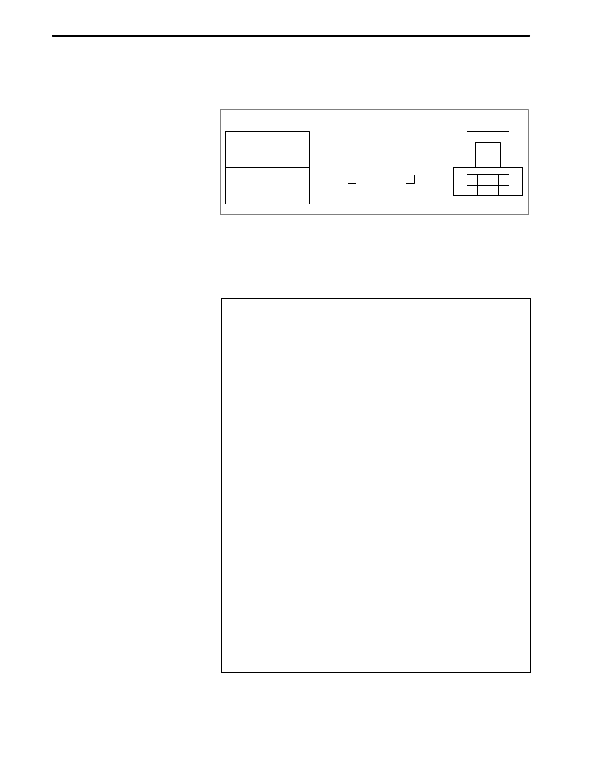
The FANUC Series 15/16/18 can be connected via a telephone line with
a personal computer available on the market to exchange CNC data
including parameters.
[Personal computer][CNC machine tool]
FANUC Series
15/16/18
RS–232C Telephone
line
Modem Modem
RS–232C
For remote diagnosis, the following functions can be executed:
1. Output of A/D conversion data 23. Output of skip position
2. Output of PMC data 24. Status output
3. Input of PMC data 25. Output of absolute position
4. Output of alarm information 26. Output of all part programs
5. Output of optional parameter 27. Output of all parameters
6. Input of optional parameter 28. Input of all parameters
7. Output of acceleration/deceleration delay
8. Output of custom macro variable
9. Input of custom macro variable 31. Output of part program
10. Output of screen information 32. Input of part program
11. Screen selection 33. Output of parameters
12. Output of machine position 34. Input of parameters
13. Output of tool offset data 35. Output of pitch error data
14. Input of tool offset data 36. Input of pitch error data
15. Output of tool life data 37. File-related function
16. Output of servo delay 38. Output of board information
17. Sequence program output 39. Display of program directory
18. Output of current sequence
number
19. Output of current program number
20. Output of actual speed 42. Input of contents of memory
21. Search of specified program 43. Output of modal information
22. Deletion of specified program
29. Deletion of all programs
30. Output of diagnostic data
40. Display of messages
41. Output of contents of memory
The word “output” used here means the reception of CNC data by the
personal computer from the Series 15, and the word “input” means the
transmission of CNC data from the personal computer to the Series 15.
4
Page 19

B–61214E–4/02
D Series16/18
SPECIFICATIONS
a. CNC program
a–1 Computer → CNC
(1)
Collation CNC command data
(2)
Search for specified program
(3)
Part program
a–2 CNC → computer
(1)
Part program
(2)
Program directory display
b. Computer → CNC
(1)
Parameter
(2)
Pitch error data
(3)
Tool offset value
(4)
Custom macro variable
(5)
Display screen selection
c. CNC → computer
(1)
Alarm information
(2)
Machine position
(3)
Absolute position
(4)
Skip position
(5)
Servo delay
(6)
Acceleration/deceleration
delay
(7)
Diagnosis
(8)
Parameter
(9)
Tool life data
(10)
Display screen status
(1 1)
Modal information
(12)
Pitch error data
(13)
Tool offset value
(14)
Custom macro variable
1. OVERVIEW
(4)
Deletion of specified program
(5)
Deletion of all programs
(3)
Current program number
(4)
Current sequence number
(6)
Contents of memory
(7)
PMC data
(8)
Display of specified message
(9)
All parameters
(15)
Contents of memory
(16)
Ladder program
(17)
Actual speed
(18)
Status
(19)
A/D conversion data
(20)
PMC data
(21)
Screen text data
(22)
PCB information
(23)
Ladder title
(24)
PMC/ladder series/version
d. File function selection
(1)
File list
(2)
File reference
(3)
Delete file
(4)
File copy
(5)
Rename file
(6)
File merge
(7)
Change directory
(8)
Create directory
(9)
Remove directory
(“→” indicates the direction of data flow.)
NOTE
1 Data may not be received in real time if the condition of the
telephone line limits the communication speed.
2 Screen text data for item (21) in c may not be usable with a
16/18–MODEL C, depending on the display unit being
used.
3 Part of the PCB information for item (22) in c may not be
usable with a 16/18–MODEL B/C.
5
Page 20

1. OVERVIEW
SPECIFICATIONS
B–61214E–4/02
1.2
CNC OPTIONS (Series 15)
Options needed to execute the remote diagnostic function are categorized
into two types: essential required options and function–specific required
options
D Essential required option
Reader/punch interface A or B
D Function–specific required options
Function name Required option
Output of A/D conversion data
Output of PMC data
Input of PMC data
Output of alarm information
Output of optional parameter
Input of optional parameter
Output of acceleration/deceleration
delay
Output of custom macro variable
Input of custom macro variable
Output of screen information
Screen selection
Output machine position
Output of tool offset data
Input of tool offset data
Output of tool life data
Output of servo delay
Output of sequence program
Output of current sequence number
Output of current program number
Output of actual speed
Search of specified program
Deletion of specified program
Output of skip position
Status output
Output of absolute position
Output of all part programs
Output of all parameters
Input of all parameters
Deletion of all programs
Output of diagnostic data
Output of part program
Input of part program
Output of parameters
Input of parameters
Output of pitch error data
Input of pitch error data
File–related function
Output of board information
Display of program directory
Display of messages
Output of contents of memory
Input of contents of memory
Output of modal information
NC window
Extended NC window
Extended NC window
NC window
NC window
NC window
Basic
NC window, Custom macro
NC window, Custom macro
Basic
Extended NC window
NC window
Extended NC window
Extended NC window
Extended NC window
Basic
Extended NC window
NC window
NC window
NC window
NC window
NC window
NC window
Extended NC window
NC window
NC window
NC window
NC window
NC window
NC window
NC window
NC window
Basic
Basic
NC window
NC window
Basic
Basic
NC window
Extended NC window,
external data I/O
Extended NC window
Extended NC window
NC window
6
Page 21
B–61214E–4/02
SPECIFICATIONS
1. OVERVIEW
1.3
SUPPORTED PERSONAL COMPUTER MODELS
The remote diagnostic function is used by executing the remote
diagnostic function executable program (RMT_MAIN.EXE) on a service
terminal.
At present, five models of personal computer can be used as a service
terminal. In addition to the remote diagnostic function executable
program, a model–specific key code file (RMT.ESC) and, on some
models, a model–specific device driver (RSDRV.SYS) are required to
execute the remote diagnostic function.
The following table lists the personal computer models that can be used
to execute the remote diagnostic function, as well as the related
model–specific key code files and device drivers.
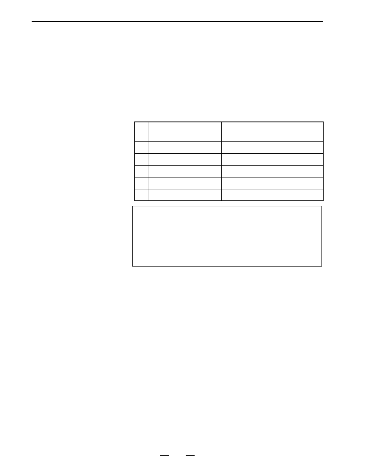
No. Supported model
1 NEC PC–98 Series For PC–98 None
2 Fujitsu FM–R Series For FM–R None
3 IBM–PC/AT or compatible For IBM–PC/AT For IBM–PC/AT
4 Toshiba Dynabook J–3100 For AX For J–3100
5 AX specification For AX For IBM–PC/A T
Model–specific
key code file
Model–specific
device driver
NOTE
1 See Sections 2.4 and 2.5 for details of the model–specific
key code file.
2 The remote diagnostic function executable program file
(RMT–MAIN.EXE) can operate only in MS–DOS
environments; it cannot operate in Windows environments.
7
Page 22

2. WORK DISK CREA TION
WORK DISK CREATION
2
SPECIFICATIONS
B–61214E–4/02
8
Page 23
B–61214E–4/02
SPECIFICATIONS
2. WORK DISK CREA TION
2.1
OVERVIEW
The remote diagnostic function is realized by executing a remote
diagnostic executable program file from the remote diagnostic work disk
(hereafter simply called the work disk) on a service terminal.
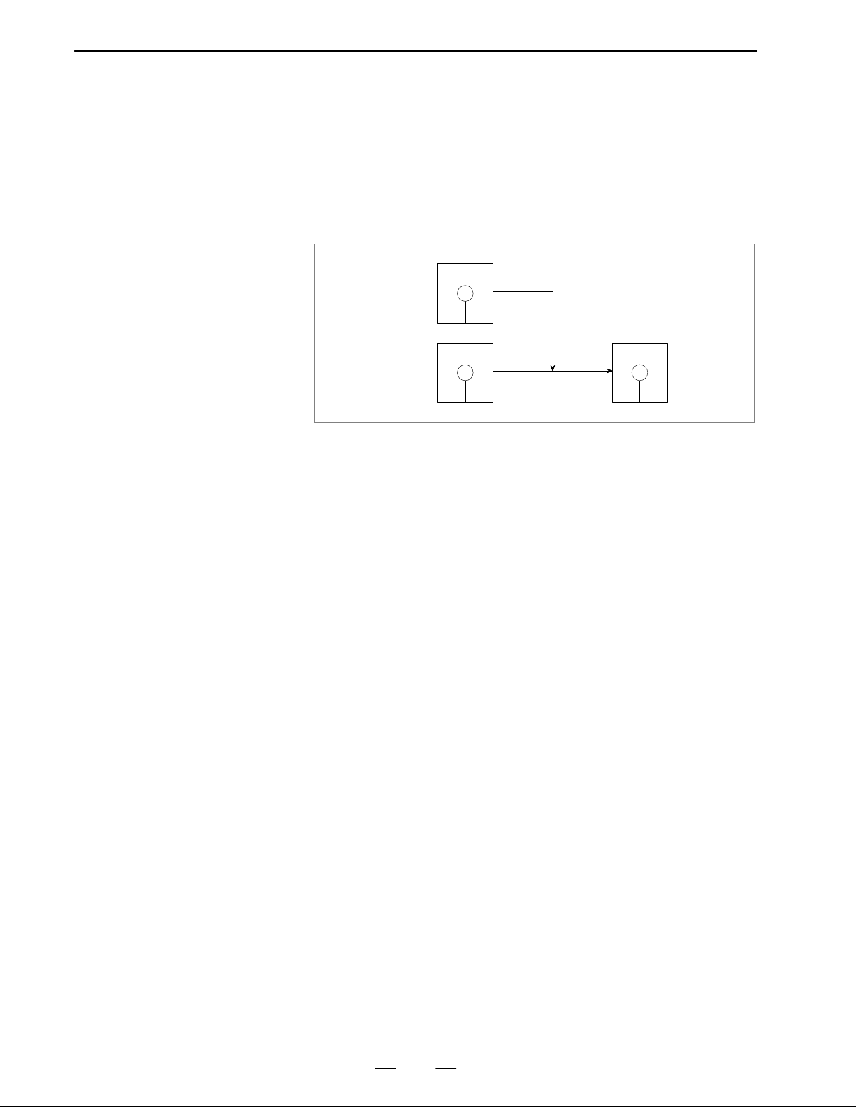
The work disk is created by adding the remote diagnostic function
terminal software (hereafter called the original disk) to the device driver
disk, as shown below.
The install program on the original disk is used to create the work disk.
Original disk
Copy
Device driver
disk
Fig. 2.1 Original disk and work disk
Work disk
9
Page 24

2. WORK DISK CREA TION
SPECIFICATIONS
B–61214E–4/02
2.2
INSTALL
PROCEDURE
This section shows an example of installing the remote diagnostic
function program. When applying the procedure, modify it as required
according to the personal computer you are using.
(1)Prerequisites
Host computer:
Must have two floppy disk drives.
Device driver disk:
Must be provided with an environment featuring an RS–232C
interface.
Original disk
See Section 2.3 for an explanation of how to create the device driver
disk.
(2)Insert the original and device driver disks into drives A and B,
respectively.
(3)Start the install program.
A: \RMT _INST [Return]
(4)Specify the host computer model.
Host : 1:IBM–PC/2:PC–98 series/3:FM–R/4:J3100/5:AX
No. : 1[Return]
(1: IBM–PC is selected.)
(5)If the Return key is pressed, drive B is selected. Proceed to step (6).
Directory for Host Software [b:\]: [Return]
At this point, you can change the program installation directory as
follows:
Directory for Host Software [b:\]: C:\RMT [Return]
(The directory is changed to C:\RMT.)
(6)Enter Y, N, or C.
Entering N returns you to step (4), where you can again specify the host
computer model. Entering C terminates the install procedure without
creating the work disk. Enter Y to proceed to step (7).
(7)Five or seven files are automatically copied from the original disk to
the work disk.
(8)Once the work disk has been created, the message “COMPLETED”
appears.
(9) Switch the host computer off, move the work disk from drive B to
drive A, then switch the host computer on again. The remote
diagnostic function starts automatically. If you changed the
installation directory in step (5), move to that directory and start the
remote diagnostic function by entering:
RMT_MAIN[Return]
10
Page 25

B–61214E–4/02
SPECIFICATIONS
2. WORK DISK CREA TION
NOTE
FANUC provides the original disk on a 5.25–inch floppy disk
(2HD) only.
11
Page 26

2. WORK DISK CREA TION
SPECIFICATIONS
B–61214E–4/02
2.3
DEVICE DRIVER DISK
When formatting a new disk, prepare a system disk as appropriate for the
host computer. (This system disk will ultimately become the work disk,
so a new disk should be used.)
Prepare an RS–232C environment on this system disk, and use it as the
device driver disk.
The following table lists the files necessary for each environment.
Host File
IBM–PC ANSI.SYS
PC–98 Series RSDRV.SYS , SPEED.EXE
FM–R SETUP.EXE
J3100 None
AX computer ANSIJ.SYS
To enable Japanese–text entry, the CONFIG.SYS file must specify the
device driver and dictionary file (for the PC9800 Series) or the device
driver (for the FMR Series), as listed below.
PC9800 Series DEVICE=A:\NECDIC.DRV A:\NECDIC.SYS. .
FMR Series DEVICE=OAK0.SYS. . . . .
DEVICE=OAK1.SYS
If the CONFIG.SYS file does not contain these statements, include them
and press the reset switch to restart the system before activating the
remote diagnostic function. For details, refer to the user’s manual of the
personal computer being used as the service terminal.
12
Page 27

B–61214E–4/02
SPECIFICATIONS
2. WORK DISK CREA TION
2.4
ORIGINAL AND WORK DISKS
(1)Common file
These files are always copied regardless of which PC is being used as
the host computer.
RMT_MAIN.EXE Remote diagnostic function executable.
program file
RMT.PCB PCB drawing number file. . . . . . . .
The following files are renamed when they are copied from the original
disk to the work disk.
(2)IBM–PC
Original disk Work disk
RMT_IBM.ESC RMT.ESC ESC key code file. . . .
RSDVIBM.SYS RSDRV.SYS RS–232C device driver. .
SPEEDIBM.EXE SPEED.EXE RS–232C port setting command. .
CF_IBM.SYS CONFIG.SYS
AT_IBM.BAT AUTOEXEC.BAT
(3)PC–98 series
Original disk Work disk
RMT_PC98.ESC RMT.ESC ESC key code file. . . .
CF_PC98.SYS CONFIG.SYS
AT_PC98.BAT AUTOEXEC.BAT
(4)FM–R
Original disk Work disk
RMT_FMR.ESC RMT.ESC ESC key code file. . . .
CF_FMR.SYS CONFIG.SYS
AT_FMR.BAT AUTOEXEC.BAT
(5)J3100
Original disk Work disk
RMT_AX.ESC RMT.ESC ESC key code file. . . .
RSDVJ3.SYS RSDRV.SYS RS–232C device driver. .
SPEEDJ3.EXE SPEED.EXE RS–232C port setting command. .
CF_J3.SYS CONFIG.SYS
AT_AX.BAT AUTOEXEC.BAT
(6)AX computer
Original disk Work disk
RMT_AX.ESC RMT.ESC ESC key code file. . . .
RSDVIBM.SYS RSDRV.SYS RS–232C device driver. .
SPEEDIBM.EXE SPEED.EXE RS–232C port setting command. .
CF_AX.SYS CONFIG.SYS
AT_AX.BAT AUTOEXEC.BAT
13
Page 28

2. WORK DISK CREA TION
SPECIFICATIONS
B–61214E–4/02
2.5
MODEL–SPECIFIC
KEY CODE FILE
On the CRT screen of the service terminal, the ESC sequence and key
codes are used to perform control.
The ESC and key codes vary with the PC being used as the service
terminal. So, compatibility among the models is maintained by
specifying ESC and key codes in a model–specific file (RMT.ESC) and
loading them from that file.
The key code file must be prepared in the same directory as the remote
diagnostic function executable program file. When the remote diagnostic
function executable program is started, it first reads the ESC and key
codes from the model–specific file. The file format is described below.
For the FM–R series
# REMOTE DIAGNOSIS ESC/KEY CODE FILE FOR FM-R SERIES Ver 1.10 #
# ESC code #
= ESC[%d;%dH # position #
= ESC[7;3%dm # reverse # Specifies inversion and color.. .
= ESC[0m # ESC cancel # Releases the ESC code.. .
= ESC[0v # cursol on # Displays the cursor.. .
= ESC[1v # cursol off # Hides the cursor.. .
= ESC[2J # display clear # Erases the screen.. .
= ESC[3%dm # collor # Specifies the color.. .
# KEY code #
= 09 # tab # [TAB] key. .
= 0d # return # [RETURN] key. .
= 1e # up # [↑] key. .
= 1f # down # [↓] key. .
= 1c # right # [→] key. .
= 1d # left # [←] key. .
= 08 # back space # [BS] key. .
= 1b # esc # [ESC] key. .
Specifies the cursor line and digit position.. .
The sequence of the codes is fixed. “=” is followed by one or more space
or tab characters, then by an [ESC] or key code.
One or more space or tab characters must also follow each [ESC] or key
code.
Text enclosed between two “#” characters is assumed to be a comment.
14
Page 29

B–61214E–4/02
SPECIFICATIONS
2. WORK DISK CREA TION
2.6
PCB DRAWING NUMBER FILE (Series 15)
Example
On the PCB information output screen, the PCB drawing number is
obtained by searching for the PCB drawing number file (RMT.PCB)
according to the module ID. Similarly to RMT.ESC, the RMT.PCB file
must be prepared in the same directory as the remote diagnostic function
executable program file. Its format is shown below.
# MODURL ID-P.C.B DRAWING No. DATA FILE #
# ID DRAWING No. COMMENTATOR #
= 0x1E/A16B-2200-0120/BASE0 512K w.IF/ *1
= 1123/A16B-2200-0141/BASE2 2M w.SUB/ *2
= 1x23/A16B-2200-0141/BASE2 2M Part2/ *3
= 0120/A16B-2200-0140/BASE2 SUB 1M/
= 0x22/A16B-2200-016x/GRAPH CPU w.MPC/
= 4x1D/A16B-2200-013x/BASE1 w.ROM B./
= 3x01/A16B-2200-0090/AXIS CTL 4Spdl/
= 1x01/A16B-2200-0092/AXIS CTL 2Spdl/
<
The sequence of the module IDs can vary . For search operations, x or X
can be used as a wild card character in any digit position of the module
ID, as in *1. (In this example, module IDs 001E, 011E to 0E1E, and 0F1E
are specified as the search targets.) If an original module ID and
corresponding module IDs that contain a wild card character are
intermixed as in *2 and *3, however, the original module ID must precede
the others (those that contain a wild card character).
Data should be described as follows: Enter “=” followed by one or more
space or tab characters, the module ID, “/”, the corresponding PCB
drawing number, another “/”, a comment, and one more “/”, in this order .
Enter “<” on the last line of the file.
The number of characters in the module ID and PCB drawing number is
fixed. However, the length of the comment can be changed, up to a
maximum of 16 characters. If more than 16 characters are specified for
a comment, the excess characters are ignored.
The comment can contain any characters except: “/”
Text enclosed between two “#” characters is assumed to be a comment.
15
Page 30

3. CONNECTION
3
CONNECTION
SPECIFICATIONS
B–61214E–4/02
16
Page 31

B–61214E–4/02
3.1
CONNECTING
MODEM
SPECIFICATIONS
3. CONNECTION
3.1.1
Connecting the CNC Machine Tool and Modem
D Series 15
Series 15
CD4A of BASE 0, CD4B
of BASE 0, or CD4 of
serial port
D Series 16/18
CNC machine tool
Main CPU board JD5A or
JD5B
A modem is to be connected to the RS-232C interface of the CNC
machine tool.
Punch
panel
Modem
RS-232C
Punch
panel
Modem
RS-232C
Telephone set
To telephone line
Telephone set
To telephone line
(1)Connect the RS–232C interface of the CNC machine tool to the punch
panel.
Series 15 supports the following three forms of RS–232C interface
connection.
D Base 0 CD4A (Reader/punch interface A is required.)
D Base 0 CD4B (Reader/punch interface A is required.)
D Serial port CD4 (Reader/punch B is required.)
Series 16/18 supports the following two forms of RS–232C interface
connection.
D Main CPU board JD5A
D Main CPU board JD5B
A connection destination is set in a parameter. See the description of
the communication parameters.
(2)Connect the punch panel with the modem via a RS-232C cable
attached to the modem.
(3)Connect the modem with the telephone line via a cable attached to the
modem.
17
Page 32

3. CONNECTION
3.1.2
Connecting Personal
Computer and Modem
SPECIFICATIONS
B–61214E–4/02
NOTE
1 Refer to the user’s manual provided with the modem for
details of how to connect the modem to the RS–232C
interface port of the CNC machine tool and the telephone
line jack.
2 For modem connection with the telephone line, the user
needs to file a terminal facility connection request with
Nippon Telegraph and Telephone Corp.
Telephone set
Personal computer
RS-232C
Modem
To
telephone
line
(1) Connect the RS-232C terminal of the personal computer with the
modem via a RS-232C cable provided for the modem.
(2)Connect the modem with the telephone line via a cable provided for
the modem.
NOTE
1 Refer to the operator’s manuals of the modem and personal
computer for the methods of connecting the personal
computer with the modem and connecting the modem with
the telephone line.
2 For modem connection with the telephone line, the user
needs to file a terminal facility connection request with
Nippon Telegraph and Telephone Corp.
18
Page 33

B–61214E–4/02
SPECIFICATIONS
3. CONNECTION
3.2
SETTING COMMUNICATION PARAMETERS
3.2.1
CNC Setting
Parameters
D
No.0000 #0 = 0 (No TV check is made.)
Define the communication parameters as follows:
Baud rate : Specify a value that matches the baud rate set
for the CNC unit and modem.
Stop bit : Specify a value that matches the number of stop
bits set in the CNC unit.
XON–XOFF control : To be applied.
Data length : 7 bits
Parity : Even
No.0000 #2 = 0 (A parity bit is provided in ISO code.)
No.0000 #4 = 0 (ISO is used for punch code.)
No.0020
No.0021
No.0022
No.0023
No.5001 Setting of device number to be connected to CD4A
No.5002 Setting of device number to be connected to CD4B
No.5003 Setting of device number to be connected to CD4
Device number → 123456
Setting of channel numbers for connection (Set to the same value.)
Connection channel CD4A of BASE0 : 1
CD4B of BASE0 : 2
CD4 of serial port : 3
5110 5120 5130 5140 5150 5160 = Device specification : 3
5111 5121 5131 5141 5151 5161 = Stop bit : 2
5112 5122 5132 5142 5152 5162 = Baud rate : 9
No.0000 #6 = 1 This setting enables the remote diagnostic function. (Set this bit to 0
when remote diagnosis is not to be performed. Never change the
communication parameter setting when this bit is set to 1.)
19
Page 34

3. CONNECTION
D Series 16/18
SPECIFICATIONS
No. 0201#0 Number of stop bits
#1 Code to be used at output time
#2 EOB to be used at output time
No. 0203 Baud rate
No. 0204 Channel used for remote diagnosis
No. 0206 Unit ID number
No. 0002#0 = 1 Enables the remote diagnostic function.
No. 0211 Password 1
No. 0212 Password 2
No. 0213 Password 3
No. 0221 Keyword 1
No. 0222 Keyword 2
No. 0223 Keyword 3
B–61214E–4/02
3.2.2
Setting for Personal
Computer
3.2.3
Setting for Modem
The setting for a personal computer depends on the type of personal
computer. Refer to the relevant operator’s manual of the personal
computer.
The setting for a modem depends on the type of modem. Refer to the
relevant operator’s manual of the modem.
20
Page 35

B–61214E–4/02
3.3
CONNECTING
TELEPHONE LINE
SPECIFICATIONS
3. CONNECTION
3.3.1
Mode of Modem
3.3.2
Line Connection
The modem has three modes: the automatic send/receive mode (AA),
manual send/automatic receive mode (MA), manual send/receive mode
(MM).
For the modulation frequency, two modes are available: the originate
mode (sender) and answer mode (receiver).
In remote diagnosis, the service center is a sender, and the user is a
receiver.
(1)Mode of service center
Set the manual send/receive mode (MM) for the modem, and set the
originate mode for the modulation frequency.
(2)Mode of user
Set the the automatic send/receive mode (AA) or manual
send/automatic receive mode (MA) when a dedicated telephone line
is made available by the user. When such a dedicated telephone line
is not available, set the the manual send/receive mode (MM). Set the
answer mode for the modulation frequency.
The method of line connection is indicated below.
(1)Manual origination and termination mode
Service center
Switch on power to the modem.
Place a call to the user.
When a beep (carrier sound) is
heard from the receiver, press the
data switch on the modem.
Start the remote diagnosis terminal
software.
Diagnosis
User
Switch on power to the modem.
Answer the phone.
Press the data switch on the modem.
Set bit 6 of parameter No. 0000 (Series 15) or bit 0
of parameter No. 0002 (Series 16/18) to 1.
21
Page 36

3. CONNECTION
.
SPECIFICATIONS
B–61214E–4/02
(2) Automatic origination and automatic termination (AA) or manual
origination and automatic termination (MA) mode
Service center
Switch on power to the modem.
Place a call to the user.
When a beep (carrier sound) is
heard from the receiver, press the
data switch on the modem.
Start the remote diagnosis terminal
software.
Diagnosis
User
Switch on power to the modem.
Set bit 6 of parameter No. 0000 (Series 15) or bit 0
of parameter No. 0002 (Series 16/18) to 1.
3.3.3
Termination
Upon the completion of diagnosis, pressing the data switch on the modem
at the service center releases the telephone line.
Service center
Diagnosis
Press the data switch on the modem to release the telephone line.
Place a call again.
User
Answer the phone.
Reset bit 6 of parameter No. 0000 (Series 15) or bit 0
of parameter No. 0002 (Series 16/18) to 0
22
Page 37

II. OPERATION
Page 38

B–61214E–4/02
1
OPERATION
FUNCTION OVERVIEW
By using a personal computer available on the market as a service
terminal connected with the FANUC Series 15/16/18 via the RS-232C
interface and telephone line, the remote diagnostic function, which
operates on MS-DOS, can monitor the status of the CNC machine and can
change CNC data using menu-driven operations.
1. FUNCTION OVERVIEW
[CNC machine tool]
FANUC Series
15/16/18
RS–232C Telephone
line
Modem Modem
[Personal
computer]
RS–232C
25
Page 39

1. FUNCTION OVERVIEW
OPERATION
B–61214E–4/02
1.1
OUTLINE
Language selection screen
Wireless adapter selection screen
Access right
confirmation screen
(Series 16/18)
Command
selection screen
Function selection
screen
The function, displayed in menu format, consists of the screens
configured as shown below. Each screen has 80 columns and 25 rows.
Program Input
Special screen for
function selection
Transmission/reception screen
File contents display
screen
1.1.1
Language Selection
Screen
Output
Fig. 1.1 Screen Configuration
Press the
key to select English, the
E
File CNC system
(Series 15 only), or the
selection
key to select Japanese for display.
J
Access right End
key to select German
G
1.1.2
Wireless Adapter
Selection Screen
This screen is used to select a wireless adapter, and to obtain information
relating to the CNC machine tool and the version of the CNC unit. If a
wireless adapter is not installed, wireless adapter selection is not
performed. A wireless adapter is available only within Japan.
26
Page 40

B–61214E–4/02
OPERATION
1. FUNCTION OVERVIEW
1.1.3
Access Right Confirmation Screen (Series 16/18)
1.1.4
Command Selection Screen
1.1.5
Function Selection Screen
Because the information relating to the CNC machine tool is protected,
a password is required to access the CNC. This screen is used to acquire
the right to access the CNC.
Press the or key to move the cursor to a desired option, then
press the
Enter
key . The screen is switched to the corresponding function
selection screen .
Press the or key to move the cursor to a desired option, then
press the
Enter
key . The screen is switched to the transmission/reception
screen of the selected function.
1.1.6
Special Screen for Function Selection
1.1.7
T ransmission/ Reception Screen
Press the or key to move the cursor to a desired option, then
press the
Enter
key . The screen is switched to the transmission/reception
of the selected function.
(1)Press the or key to move the cursor to a desired option.
Data of up to 12 columns can be specified for most options. For some
special functions, data of up to 32 columns can be specified.
(2)In the item of DATA KEEP FILE NAME, specify the name of a file
to hold data read from the CNC machine. If no file name is specified,
data read from the CNC machine is held in the default file A.DAT.
(3)To start communication, move the cursor to EXECUTE by pressing
key.
Enter
key. To stop
the
or key, then press the
communication in progress, press the
ESC
(4)To return to the previous function selection screen or special screen for
function selection, move the cursor to RETURN by pressing the
or key, then press the
Enter
key.
(5)Communication status is indicated in the status display section at the
bottom of the screen. The status display section and key functions are
shown below.
27
Page 41

1. FUNCTION OVERVIEW
OPERATION
B–61214E–4/02
MODE: STOP
TAB
: Specifies data display during transmission /reception
Fig. 1.1.7 Status display section and key functions
FILE INFORM:
: Selection : Execution
Enter
****
END CODE:
DISP. DATA
IN TRS/RCV
ON OFF
ESC
: Stop
D MODE : The current status, stop, transmission, or
reception, is indicated.
D FILE INFORMATION : The file status, new, existing, or
additional, is indicated.
D END CODE : The result of communication is
indicated by a code. The message
corresponding to the code is also
indicated in the right-hand part above
the status display section.
D Blank section : Data being transmitted or received is
indicated. When DISP.DATA IN
TRS/RCV is OFF, data is not indicated.
DISP.DA TA IN TRS/RCV is turned ON
or OFF by pressing the
TAB
key.
28
Page 42

B–61214E–4/02
OPERATION
1. FUNCTION OVERVIEW
The following table lists the completion status codes together with the
corresponding messages.
Completion
status code
–1 1 Error
(Processing necessary to
start the NC command data
has not been completed.)
–10 Reject
(The previously specified
processing has not been
completed.)
–2 CNC reset status CNC reset status
–1 Reject
(Other processing is being
executed.)
0 Normal end Normal end
1 Error (function code error) A function code error oc-
2 Error (data length error) A data length error occurred.
3 Error (data number error) A data number error oc-
Meaning Message text
The NC command data has
not been completed.
The previous processing has
not been completed.
Rejected.
curred.
curred.
1.1.8
File contents Display Screen
4 Error (data attribute error) A data attribute error oc-
curred.
5 Error (data error) A data error occurred.
6 Error (no option) There is no option.
7 Error (write–protected) Write–protected.
8 Error (memory overflow) A memory overflow oc-
curred.
25 Error
(At the end of the previous
processing, other processing
was specified.)
Information about proces-
sing other than the previous
processing was reported.
(1)When all data transmitted from the CNC machine is read, the
transmission/reception screen is automatically switched to the file
contents display screen. The screen displays the data written into a
specified file.
(2) If data written into a file requires more than one screen, the data is
shown in the scroll mode. To stop scrolling, press the
Ctrl
key and
key. To restart scrolling, press the
S
Ctrl
key and
(3)To return to the transmission/reception screen, press the
29
Q
ESC
key.
key.
Page 43

2. FUNCTIONS
2
FUNCTIONS
OPERATION
The remote diagnostic function is started as described below.
Insert the floppy disk containing the absolute loader of the remote
diagnostic function into drive A of the personal computer. Then, enter the
following to start the function:
A: \rmt_main [Return]
B–61214E–4/02
30
Page 44

B–61214E–4/02
OPERATION
2. FUNCTIONS
2.1
LANGUAGE SELECTION SCREEN
When the remote diagnostic function is started, the language selection
screen is displayed. On the screen, select a desired language from the
menu.
* * * * * * * * * * * * * * * *
* *
* REMOTE DIAGNOSIS *
* *
* * * * * * * * * * * * * * * *
Ver 2.01
<SELECT LANGUAGE>
PUSH KEY [E] : ENGLISH
[G] : GERMAN (FS15 ONLY)
[J] : JAPANESE
[ESC] : END
Fig. 2.1 Language selection screen
Press the
E
or
Enter
key to select English. Press the
G
key to
select German (Series 15 only). Press the
key to select Japanese.
J
Then, the screen changes to the command selection screen, which is
displayed in the language specified.
To terminate the remote diagnostic function, press the
ESC
key.
In the text that follows, an explanation is given using the screens in
English.
31
Page 45

2. FUNCTIONS
OPERATION
B–61214E–4/02
2.2
WIRELESS ADAPTER SELECTION SCREEN
After a language has been selected on the language selection screen, the
wireless adapter selection screen appears automatically.
This screen is used to select a wireless adapter.
* * * * * WIRELESS ADAPTER SELECTION * * * * *
REMOTE WIRELESS ADAPTER NUMBER : _
IGNORE THIS PROMPT, IF NO WIRELESS ADAPTER IS
IN USE.
“PREPARING”
[][]:SELECT [Return]:EXECUTE [ESC]:END
Fig. 2.2 Wireless adapter selection screen
REMOTE WIRELESS ADAPTER NUMBER:
Select the wireless adapter number of a substation. This can be
specified using up to two digits. If you are not using a wireless adapter,
do not enter anything. (In this case, wireless adapter communication
is not performed.)
Pressing the
Enter
key triggers communication according to the wireless
adapter selection.
After selecting a wireless adapter, perform “system information read” and
“function version/ID output.”
The message “PREP ARING” is displayed while communication is being
performed.
Communication is aborted by pressing the
ESC
key.
NOTE
The wireless adapter is available only within Japan.
Upon the completion of communication, the access right confirmation
screen appears automatically.
The remote diagnostic function is terminated by pressing the
ESC
key.
32
Page 46

B–61214E–4/02
OPERATION
2. FUNCTIONS
2.3
ACCESS RIGHT CONFIRMATION SCREEN (Series 16/18)
After communication on the wireless adapter selection screen has been
completed, the access right confirmation screen is automatically
displayed.
***** ACCESS RIGHT CONFIRMATION SCREEN * ****
DIAGNOSIS START PASSWOR : XXXXXXXX
SYSTEM INFORMATION : FS16–TT SYSTEM, MAIN
ROM SERIES/VERSION : B101–0001
FUNCTION VERSION : 2.0
UNIT ID NUMBER : XX
NUMBER OF CONTROLLED AXES : 8
“THE ENTERED PASSWORD IS INVALID”
EXECUTE
RETURN
[][]:SELECT [Return]:EXECUTE
Fig. 2.3 Access right confirmation screen
DIAGNOSIS START PASSWORD:
Specify the password needed to acquire the right to access the CNC
machine tool. A password of up to eight digits can be specified.
After moving the cursor to “EXECUTE” using the
press the
Enter
key. Communication begins.
and keys,
As a result of communication, the command selection screen is
automatically displayed, provided the password is valid. If the password is
invalid, the message “THE ENTERED PASSWORD IS INVALID” is
displayed.
To terminate the remote diagnostic function, position the cursor to
“RETURN” and press the
Enter
key. The wireless adapter is closed and
terminated.
The access right screen also displays system information related to the
CNC unit. This information includes the following items:
SYSTEM INFORMATION:
The system information is displayed according to the CNC system
information.
ROM SERIES/VERSION:
The ROM series/version is displayed according to the CNC system
information.
FUNCTION VERSION:
The function version obtained at function version output is displayed.
UNIT ID NUMBER:
The CNC machine tool ID obtained at function version output is
displayed.
33
Page 47

2. FUNCTIONS
OPERATION
B–61214E–4/02
NUMBER OF CONTROLLED AXES:
The number of controlled axes obtained from the CNC system
information is displayed.
Refer to the FANUC Series 16/18 MODEL–C Parameter Manual
(B–62760EN) for details of the supported password types and how to set
them.
34
Page 48

B–61214E–4/02
OPERATION
2. FUNCTIONS
2.4
COMMAND SELECTION SCREEN
After communication on the access right confirmation screen has been
completed, the command selection screen is automatically displayed.
* * * * * * * * * * * * * * * * * * * *
* *
REMOTE DIAGNOSIS COMMAND SELECTION
* *
* *
* * * * * * * * * * * * * * * * * * * *
REMOTE DIAGNOSTIC FUNCTION SELECTION (CNC PROGRAM)
REMOTE DIAGNOSTIC FUNCTION SELECTION (COMPUTERCNC)
REMOTE DIAGNOSTIC FUNCTION SELECTION (CNCCOMPUTER)
FILE FUNCTION SELECTION
CNC SYSTEM SELECTION
ACCESS RIGHT REQUEST
END
[↑][↓]:SELECT [Return]:EXECUTE
Fig. 2.4 Command selection screen
Select any of the following functions:
D REMOTE DIAGNOSTIC FUNCTION SELECTION
(CNC PROGRAM)
D REMOTE DIAGNOSTIC FUNCTION SELECTION
(COMPUTER → CNC)
D REMOTE DIAGNOSTIC FUNCTION SELECTION
(CNC → COMPUTER)
D FILE FUNCTION SELECTION
D CNC PATH SELECTION
D ACCESS RIGHT REQUEST
The remote diagnostic function is terminated by selecting “END,” then
connecting to another wireless adapter, or by quitting the function.
(1)CNC program function selection screen
(REMOTE DIAGNOSTIC FUNCTION (CNC PROGRAM))
This screen is used as the menu to access a CNC program.
By using the menu of functions on the screen, a CNC program can be
searched for, a file that contains a CNC program created on the service
terminal can be registered in the CNC machine, and file contents can
be compared with those in the CNC machine. In addition, all or some
programs can be displayed or deleted, the current program number and
current sequence number can be displayed on the service terminal, and
data can be stored in a file.
(2)Input function selection screen
(REMOTE DIAGNOSTIC FUNCTION (COMPUTER → CNC))
This screen is used as the menu to change CNC data.
By using the screen, data frequently used by the operator can be set in
the CNC machine. Such data includes parameters, pitch error data,
offset data, macro variables, and the contents of memory . This screen
can also be used to switch between the CNC screens and to output
messages.
35
Page 49

2. FUNCTIONS
OPERATION
B–61214E–4/02
(3)Output function selection screen
(REMOTE DIAGNOSTIC FUNCTION (CNC → COMPUTER))
This screen is used as the menu to monitor the status of the CNC
machine.
By using the screen, data frequently used by the operator can be
displayed on the service terminal, and can also be stored in a file. Such
data includes parameters, pitch error data, offset data, macro variables,
tool life data, and modal information.
If an abnormality occurs on the CNC machine, information such as
alarm information, diagnosis data, PMC data, PC board information
can be displayed on the service terminal and stored in a file. This
capability allows the operator to obtain the status of the CNC machine
on a real-time basis and to take quick action.
(4)File function selection screen (FILE)
This screen is used as the menu for file management.
By using the screen, the contents of a file created with a CNC program
function or output function can be displayed, and a list of file names
can be displayed.
In addition, operations such as file name alteration, file movement, file
deletion, directory creation, and directory movement can performed
for file maintenance.
(5)CNC path selection screen (CNC PATH SELECTION)
This screen is used to select the CNC path to be accessed by the remote
diagnostic function. To access the TT system CNC, select either the
main path or subpath. For the T and M systems, the cursor is
positioned to “MAIN.”
(6)Access right request screen (ACCESS RIGHT REQUEST)
This screen is used to request the acquiring of the right to access
parameters and part programs protected on the CNC side.
(7)End screen (END)
This screen is used to select the performing of diagnosis on another
CNC machine tool using a wireless adapter, or to terminate remote
diagnosis.
36
Page 50

B–61214E–4/02
OPERATION
2. FUNCTIONS
2.5
CNC PROGRAM FUNCTION
When the REMOTE DIAGNOSIS SELECTION (CNC PROGRAM)
option is selected on the command selection screen, the following screen
is displayed.
***** REMOTE DIAGNOSIS SELECTION (CNC PROGRAM) *****
SPECIFIED–PROGRAM SEARCH CURRENT SEQUENCE NUMBER
PART PROGRAM PROGRAM DIRECTORY DISPLAY
(COMPUTER → CNC) (CNC → COMPUTER)
COLLATION CNC COMMAND DATA SPECIFIED–PROGRAM DELETION
(COMPUTER → CNC)
PART PROGRAM ALL–PROGRAM DELETION
(CNC → COMPUTER)
CURRENT PROGRAM NUMBER
(CNC → COMPUTER)
[][]:
SELECT [Return]: EXECUTE [ESC]:END
Fig. 2.5 CNC Program function selection screen
(CNC → COMPUTER)
When a desired item is selected by positioning the cursor with the
and keys, then pressing the
Enter
key, the transmission/reception
screen for the corresponding function is displayed.
The SPECIFIED–PROGRAM DELETION and ALL–PROGRAM
DELETION options are normally not displayed. They appear only when
the
The command selection screen is displayed again by pressing the
key is pressed.
P
ESC
key.
37
Page 51

2. FUNCTIONS
OPERATION
B–61214E–4/02
2.5.1
Search for Specified
Program
When the SPECIFIED–PROGRAM SEARCH option is selected on the
CNC program selection screen, the following transmission/reception
screen is displayed:
SPECIFIED–PROGRAM SEARCH
CURRENT DIR B:\RMT
PROGRAM NUMBER :
EXECUTE
RETURN
*****
The status display section and key functions *****
Fig. 2.5.1 Specified–program search screen
PROGRAM NUMBER:
Specifying the number of a program for which a search is to be made
causes the corresponding CNC program to be displayed on the CNC
program screen.
2.5.2
Part Program
(Computer → CNC)
When the PART PROGRAM (COMPUTER → CNC) option is selected
on the CNC program selection screen, the following transmission/
reception screen is displayed:
PART PROGRAM (COMPUTER → CNC)
CURRENT DIR B:\RMT
COMMAND DATA FILE NAME :
EXECUTE
RETURN
***** The status display section and key functions *****
Fig. 2.5.2 Part program screen
COMMAND DATA FILE NAME:
Specifying the name of a file in which a CNC program was created
causes the program to be registered with the CNC.
38
Page 52

B–61214E–4/02
OPERATION
2. FUNCTIONS
NOTE
This function can be executed only when the CNC is in EDIT
mode. If an attempt is made to execute it in any other mode,
the error message “WRITE–PROTECTED” appears. In
addition, this function cannot be executed when the
machine tool is in the emergency stop state.
2.5.3
Collation CNC
Command Data
(Computer → CNC)
When the COLLATION CNC COMMAND DATA (COMPUTER →
CNC) option is selected on the CNC program selection screen, the
following transmission/reception screen is displayed:
COLLATION CNC DATA (COMPUTER → CNC)
CURRENT DIR B:\RMT
COMMAND DATA FILE NAME :
EXECUTE
RETURN
***** The status display section and key functions *****
Fig. 2.5.3 Collation CNC command data screen
COMMAND DATA FILE NAME:
Specifying the name of a file in which a CNC program was created
causes that program to be collated with a CNC program having the
same program number.
Provided no mismatch is detected, the message “NORMAL END”
appears. If a mismatch is detected, the message “DATA ERROR”
appears.
NOTE
This function can be executed only when the CNC is in EDIT
mode. If an attempt is made to execute it in any other mode,
the error message “WRITE–PROTECTED” appears. In
addition, this function cannot be executed when the
machine tool is in the emergency stop state.
39
Page 53

2. FUNCTIONS
OPERATION
B–61214E–4/02
2.5.4
Part Program
(CNC → Computer)
When the PART PROGRAM option is selected on the CNC program
selection screen, the following transmission/reception screen appears:
PART PROGRAM (CNC → COMPUTER)
CURRENT DIR B:\RMT
PROGRAM NUMBER :
–1 = ALL PROGRAMS
DATA KEEP FILE NAME :
EXECUTE
RETURN
***** The status display section and key functions *****
Fig. 2.5.4 Part program screen
PROGRAM NUMBER:
Specify the program number of the program to be read. Specifying
“–1” causes all programs to be read from the CNC.
DATA KEEP FILE NAME:
Specify the name of the file to which a part program is to be saved.
D When a single program
is stored
After the data has been read, the transmission/reception screen is
automatically switched to the file contents display screen.
PART PROGRAM (CNC → COMPUTER)
PROGRAM NUMBER :1234
%
01234
N10G92X0Y0Z0
N20G01X100.0F100.0
N30X-50.0F150.0
N40Y150.0F100.0
N50Z-10.0F90.0
M02
%
40
Page 54

B–61214E–4/02
D When all programs are
stored
OPERATION
PART PROGRAM (CNC → COMPUTER)
ALL PROGRAM
%
O0100
N10G92X0Y0Z0
N20G01X100.0F100.0
N30X-50.0F150.0
M02
O0200
N10G92X0Y0Z0
N20G01X100.0F100.0
N30X-50.0F150.0
M02
O0300
N10G92X0Y0Z0
N20G01X100.0F100.0
2. FUNCTIONS
2.5.5
Current Program
Number
(CNC → Computer)
When the CURRENT PROGRAM NUMBER (CNC → COMPUTER)
options is selected from the CNC program selection screen, the following
transmission/reception screen is displayed:
CURRENT PROGRAM NUMBER (CNC → COMPUTER)
CURRENT DIR B:\RMT
DATA KEEP FILE NAME :
EXECUTE
RETURN
***** The status display section and key functions *****
Fig. 2.5.5 Current program number screen
DATA KEEP FILE NAME:
Specify the name of the file to which the program being executed is
to be saved.
After the data has been read, the transmission/reception screen is
automatically switched to the file contents display screen.
CURRENT PROGRAM NUMBER (CNC → COMPUTER)
CURRENT PROGRAM NUMBER: 2000
MAIN PROGRAM NUMBER : 1000
41
Page 55

2. FUNCTIONS
OPERATION
B–61214E–4/02
NOTE
MAIN PROGRAM NUMBER is not displayed if the CNC is
currently executing the main program.
2.5.6
Current Sequence
Number
(CNC → Computer)
When the CURRENT SEQUENCE NUMBER (CNC → COMPUTER)
option is selected from the CNC program selection screen, the following
transmission/reception screen is displayed:
CURRENT SEQUENCE NUMBER (CNC → COMPUTER)
CURRENT DIR B:\RMT
DATA KEEP FILE NAME :
EXECUTE
RETURN
***** The status display section and key functions *****
Fig. 2.5.6 Current sequence number screen
DATA KEEP FILE NAME:
Specify the name of the file to which the sequence being executed is
to be saved.
After the data has been read, the transmission/reception screen is
automatically switched to the file contents display screen.
CURRENT SEQUENCE NUMBER OUTPUT
CURRENT SEQUENCE NUMBER
42
Page 56

B–61214E–4/02
OPERATION
2. FUNCTIONS
2.5.7
Program Directory
Display
(CNC → Computer)
When the PROGRAM DIRECTOR Y DISPLA Y (CNC→ COMPUTER)
option is selected from the CNC program selection screen, the following
transmission/reception screen is displayed:
PROGRAM DIRECTORY DISPLAY (CNC → COMPUTER)
CURRENT DIR B:\RMT
COMMENT :
0 = NO
1 = YES
START PROGRAM NUMBER :
0 = START FROM PROGRAM 1
END PROGRAM NUMBER :
0 = TO THE LAST PROGRAM
DATA KEEP FILE NAME :
EXECUTE
RETURN
***** The status display section and key functions *****
Fig. 2.5.7 Program directory display screen
D If no comment display is
requested
COMMENT:
Specify whether comments are specified. If 0 is entered, only program
numbers are read. If 1 is entered, comment text and the size of the
memory being used (in characters) are read together with the program
numbers. If a number other than 0 or 1 is entered, only program
numbers are read.
START PROGRAM NUMBER:
Specify the number of the first program to be read. If 0 is entered,
program read begins from program number 1.
END PROGRAM NUMBER:
Specify the number of the last program to be read. If 0 is entered, all
programs up to the last one are read.
DATA KEEP FILE NAME:
Specify the name of the file to which the program directory is to be
saved.
After the data has been read, the transmission/reception screen is
automatically switched to the directory display screen.
PROGRAM DIRECTORY DISPLAY (CNC → COMPUTER)
O0001 O0002 O0010 01000 O2000 05000
O6000 O8005 O9000 O9990
43
Page 57

2. FUNCTIONS
D If comment display is
requested
OPERATION
PROGRAM DIRECTORY DISPLAY (CNC → COMPUTER)
O0001 (SHAFT–1000.MAIN)80
O0002 (SHAFT–2000.MAIN)80
O1000 ()80
B–61214E–4/02
2.5.8
Deletion of Specified Program
When the SPECIFIED PROGRAM DELETE option is selected on the
CNC program function selection screen, the following transmission/
reception screen is displayed:
SPECIFIED–PROGRAM DELETION
CURRENT DIR B:\RMT
PROGRAM NUMBER :
EXECUTE
RETURN
***** The status display section and key functions *****
Fig. 2.5.8 Specified–program deletion screen
PROGRAM NUMBER:
If a program number is entered, the CNC deletes the corresponding
CNC program.
44
Page 58

B–61214E–4/02
OPERATION
2. FUNCTIONS
2.5.9
Deletion of All Programs
When the ALL PROGRAM DELETE option is selected on the CNC
program function selection screen, the following transmission/reception
screen is displayed:
ALL–PROGRAM DELETION
CURRENT DIR B:\RMT
:
EXECUTE
RETURN
***** The status display section and key functions *****
Fig. 2.5.9 Screen for deletion of all programs
When this function is executed, all part programs are deleted.
45
Page 59

2. FUNCTIONS
OPERATION
B–61214E–4/02
2.6
INPUT FUNCTION
(COMPUTER → CNC)
When the REMOTE DIAGNOSIS (COMPUTER → CNC) option is
selected on the command selection screen, the following screen is
displayed:
***** REMOTE DIAGNOSIS (COMPUTER → CNC) *****
PARAMETER OPTION PARAMETER
PITCH ERROR DATA ALL PARAMETER
TOOL OFFSET DATA
CUSTOM MACRO VARIABLE
DISPLAY SELECTION
MEMORY CONTENTS
PMC DATA
1 SPECIFIED MESSAGE DISPLAY
[][]:SELECT [Return]:EXECUTE [ESC]:END
Fig. 2.6 Function selection screen
(Series15 ONLY)
When a desired item is selected by positioning the cursor with the
and keys, then pressing the
Enter
key, the transmission/reception
screen for the corresponding function or the special screen for selecting
the display selection function is displayed.
The command selection screen is displayed again by pressing the
ESC
key.
46
Page 60

B–61214E–4/02
OPERATION
2. FUNCTIONS
2.6.1
Parameter
(Computer → CNC)
When the PARAMETER option is selected on the function selection
screen, the following transmission/reception screen is displayed:
PARAMETER (COMPUTER → CNC)
CURRENT DIR B:\RMT
PARAMETER NUMBER :
AXIS NUMBER :
0 = NO AXIS
1n = EACH AXIS
–1 = ALL AXES
PARAMETER DATA :
EXECUTE
RETURN
***** The status display section and key functions *****
Fig. 2.6.1 Parameter input screen
PARAMETER NUMBER:
Specify the number of a parameter to be changed.
With the Series 16/18, optional parameters can also be changed.
AXIS NUMBER:
To change the parameter of an axis, specify the axis number.
To change the parameter with no axis specified, enter zero.
To change the parameters of all axes, specify –1.
PARAMETER DATA:
Specify of the following:
Decimal number (digits only)
Binary number (followed by b or B)
Hexadecimal number (followed by h or H)
47
Page 61

2. FUNCTIONS
OPERATION
B–61214E–4/02
2.6.2
Pitch Error Data
(Computer → CNC)
When the PITCH ERROR DATA option is selected on the input function
selection screen, the following transmission/reception screen is
displayed:
PITCH ERROR DATA (COMPUTER → CNC)
CURRENT DIR B:\RMT
PITCH ERROR DATA NUMBER :
PITCH ERROR DATA :
EXECUTE
RETURN
***** The status display section and key functions *****
Fig. 2.6.2 Screen for pitch error data input
PITCH ERROR DATA NUMBER:
Specify the number of pitch error data to be changed.
PITCH ERROR DATA:
Specify new pitch error data.
2.6.3
Tool Offset Data
(Computer → CNC)
When the TOOL OFFSET DAT A option is selected on the input function
selection screen, the following special screen for function selection is
displayed:
***** TOOL OFFSET DATA (COMPUTER → CNC) *****
WEAR
GEOMETRY
[↑][↓]:SELECT [Return]:EXECUTE [ESC]:END
Fig. 2.6.3 (a) Special screen for specifying tool offset data
Select an offset data item to be changed, WEAR or GEOMETRY.
48
Page 62

B–61214E–4/02
OPERATION
2. FUNCTIONS
(1)Tool offset data – wear (Series 15)
TOOL OFFSET DATA – WEAR (COMPUTER → CNC)
CURRENT DIR B:\RMT
CNC MACHINE :
0=M SYSTEM, 1=T/TT SYSTEM
DATA TYPE :
M SYSTEM T SYSTEM
0=CUTTER COMPENSATION 0=X 2=NOSE RADIUS 4=Y
1=LENGTH COMPENSATION 1=z 3=IMAGINARY NOSE
OFFSET NUMBER :
OFFSET VALUE :
EXECUTE
RETURN
***** The status display section and key functions *****
Fig. 2.6.3 (b) Wear input screen (Series 15)
CNC MACHINE:
Specify whether the CNC machine is a machining center or lathe.
DATA TYPE:
Specify the type of offset data to be changed.
OFFSET NUMBER:
Specify the number of offset data to be changed.
OFFSET VALUE:
Specify new offset data.
(2)Tool offset data – geometry (Series 15)
TOOL OFFSET DATA – GEOMETRY (COMPUTER → CNC)
CURRENT DIR B:\RMT
CNC MACHINE :
0=M SYSTEM, 1=T/TT SYSTEM
DATA TYPOE :
M SYSTEM T SYSTEM
0=CUTTER COMPENSATION 0=X 2=NOSE RADIUS 4=Y
1=LENGTH COMPENSATION 1=z 3=IMAGINARY NOSE
OFFSET NUMBER :
OFFSET VALUE :
EXECUTE
RETURN
***** The status display section and key functions *****
Fig. 2.6.3 (c) Geometry screen (Series 15)
CNC MACHINE :
Specify whether the CNC machine is a machining center or lathe.
DATA TYPE : Specify the type of offset data to be changed.
OFFSET NUMBER: Specify the number of offset data to be changed.
OFFSET VALUE : Specify new offset data.
49
Page 63

2. FUNCTIONS
OPERATION
B–61214E–4/02
(3)Tool offset data – wear (Series 16/18 M series)
TOOL OFFSET DATA – WEAR (COMPUTER → CNC)
CURRENT DIR B:\RMT
DATA TYPE :
0 = CUTTER COMPENSATION
1 = LENGTH COMPENSATION
OFFSET NUMBER :
OFFSET VALUE :
EXECUTE
RETURN
***** The status display section and key functions *****
Fig. 2.6.3 (d) Wear input screen (Series 16/18 M series)
DATA TYPE : Specify the type of the offset data to be updated.
OFFSET NUMBER: Specify the number of the offset data to be updated.
OFFSET V ALUE : Sp ec if y a v al ue w it h w hi ch t o update the offset data.
(4)Tool offset data – wear (Series 16/18 T series)
TOOL OFFSET DATA – WEAR (COMPUTER → CNC)
CURRENT DIR B:\RMT
DATA TYPE: :
0 = X 2 = NOSE RADIUS 4 = Y
1 = z 3 = IMAGINARY NOSE
OFFSET NUMBER :
OFFSET VALUE :
EXECUTE
RETURN
***** The status display section and key functions *****
Fig. 2.6.3 (e) Wear input screen (Series 16/18 T series)
50
Page 64

B–61214E–4/02
OPERATION
(5)Tool offset data – geometry (Series 16/18 M series)
TOOL OFFSET DATA – GEOMETRY (COMPUTER → CNC))
CURRENT DIR B:\RMT
DATA TYPE :
0 = CUTTER COMPENSATION
1 = LENGTH COMPENSATION
OFFSET NUMBER :
OFFSET VALUE :
EXECUTE
RETURN
***** The status display section and key functions *****
Fig. 2.6.3 (f) Geometry input screen (Series 16/18 M series)
(6)Tool offset data – geometry (Series 16/18 T series)
2. FUNCTIONS
TOOL OFFSET DATA – GEOMETRY (COMPUTER → CNC)
CURRENT DIR B:\RMT
DATA TYPE :
0=X 2=NOSE RADIUS 4=Y
1=z 3=IMAGINARY NOSE
OFFSET NUMBER :
OFFSET VALUE :
EXECUTE
RETURN
***** The status display section and key functions *****
Fig. 2.6.3 (g) Geometry input screen (Series 16/18 T series)
DATA TYPE : Specify the type of the offset data to be updated.
OFFSET NUMBER: Specify the number of the offset data to be updated.
OFFSET V ALUE : Specify a val ue wi th whi ch to update the offset data.
51
Page 65

2. FUNCTIONS
OPERATION
B–61214E–4/02
2.6.4
Custom Macro Variable
(Computer → CNC)
When the CUSTOM MACRO VARIABLE option is selected on the input
function selection screen, the following transmission/reception screen is
displayed:
CUSTOM MACRO VARIABLE (COMPUTER → CNC)
CURRENT DIR B:\RMT
MACRO VARIABLE NUMBER :
MACRO VARIABLE DATA :
EXECUTE
RETURN
***** The status display section and key functions *****
Fig. 2.6.4 Custom macro inoput screen
MACRO VARIABLE NUMBER :
Specify the umber of a macro variable to be changed.
MACRO VARIABLE DATA : Specify new data.
NOTE
If the number of digits to be assigned to a macro variable
exceeds 8, it can be entered from the computer, but it is not
assigned to the macro variable.
52
Page 66

B–61214E–4/02
OPERATION
2. FUNCTIONS
2.6.5
Display Selection
(Computer → CNC)
When the DISPLAY SELECTION option is selected on the input
function selection screen, the following special screen for function
selection is displayed:
***** DISPLAY SELECTION (COMPUTER → CNC) *****
POSITION MENU PROGRAM
PROGRAM GRAPHIC
OFFSET CONVERSATIONAL MACRO
PROGRAM CHECK
SETTING
SERVICE
MESSAGE
[↑][↓]:SELECT [Return]:EXECUTE [ESC] : END
Fig. 2.6.5 (a) Special screen for selecting display selection function
(Series 15)
***** DISPLAY SELECTION (COMPUTER → CNC) *****
POSITION
PROGRAM
OFFSET
SYSTEM
DIAGNOSIS
MESSAGE
GRPH
PMC
[↑][↓]:SELECT [Return]:EXECUTE [ESC] : END
Fig. 2.6.5 (b) Special screen for selecting display selection function
(Series 16/18)
NOTE
With the Series 16/18, this function cannot be executed for
CNC subpath. Moreover, if the system’s PMC screen is
open on the CNC side, this function cannot be used to
switch to another screen.
53
Page 67

2. FUNCTIONS
OPERATION
(1)Display selection – current position
DISPLAY SELECTION – POSITION (COMPUTER → CNC)
CURRENT DIR B:\RMT
CHAPTER SELECTION :
0=ALL 5=BLOCK RESTART
1=RELATIVE 6=PROGRAM RESTART
2=ABSOLUTE 7=TOOL TIP
3=MACHINE 8=PULSE
4=MANUAL INTERRUPTION
EXECUTE
RETURN
***** The status display section and key functions *****
Fig. 2.6.5 (c) Current position selection screen (Series 15)
B–61214E–4/02
DISPLAY SELECTION – POSITION (COMPUTER → CNC)
CURRENT DIR B:\RMT
CHAPTER SELECTION :
0=ABSOLUTE POSITION DISPLAY 3=HANDLE INTERRUPT
1=RELATIVE POSITION DISPLAY 4=OPERATING MONITOR
OVERALL POSITION DISPLAY
2=
EXECUTE
RETURN
***** The status display section and key functions *****
Fig. 2.6.5 (d) Current position selection screen (Series 16/18)
CHAPTER SELECTION:
Specify the chapter to be selected on the CNC screen.
54
Page 68

B–61214E–4/02
OPERATION
(2)Display selection –program
DISPLAY SELECTION – PROGRAM (COMPUTER → CNC)
CURRENT DIR B:\RMT
CHAPTER SELECTION :
0=MEMORY 4=TIME
1=LIBRARY 5=SCHEDURE
2=HIGH–SPEED MACHINING LIBRARY
3=FLOPPY LIBRARY
EXECUTE
RETURN
***** The status display section and key functions *****
Fig. 2.6.5 (e) Program selection screen (Series 15)
2. FUNCTIONS
DISPLAY SELECTION – PROGRAM (COMPUTER → CNC)
CURRENT DIR B:\RMT
EXECUTE
RETURN
***** The status display section and key functions *****
Fig. 2.6.5 (f) Program selection screen (Series 16/18)
CHAPTER SELECTION:
Specify the chapter to be selected on the CNC screen (Series 15 only).
55
Page 69

2. FUNCTIONS
OPERATION
(3)Display selection – offset
DISPLAY SELECTION – OFFSET (COMPUTER → CNC)
CURRENT DIR B:\RMT
CHAPTER SELECTION :
0=TOOL OFFSET 4=TOOL MEASURE
1=GEOMETRY OFFSET 5=TOOL DATA
2=WORK ZERO OFFSET
3=TOOL POST FORM
EXECUTE
RETURN
***** The status display section and key functions *****
Fig. 2.6.5 (g) Offset selection screen (Series 15)
B–61214E–4/02
DISPLAY SELECTION – OFFSET (COMPUTER → CNC)
CURRENT DIR B:\RMT
CHAPTER SELECTION :
0=OFFSET 4=MENU
1=SETTING 5=OPERATOR’S PANEL
2=WORK COORDINATES 6=TOOL LIFE DATA
3=MACRO VARIABLE
EXECUTE
RETURN
***** The status display section and key functions *****
Fig. 2.6.5 (h) Offset selection screen (Series 16/18)
CHAPTER SELECTION:
Specify the chapter to be selected on the CNC screen.
56
Page 70

B–61214E–4/02
OPERATION
(4)Display selection – program check (Series 15)
DISPLAY SELECTION–PROGRAM CHECK (COMPUTER→CNC)
CURRENT DIR B:\RMT
CHAPTER SELECTION :
0=CHECK 4=BUFFER 1
1=LAST BLOCK 5=BUFFER 2
2=CURRENT BLOCK 6=BUFFER 3
3=NEXT BLOCK 7=OPERATOR’S MONITOR
EXECUTE
RETURN
***** The status display section and key functions *****
Fig. 2.6.5 (i) Program check selection screen
CHAPTER SELECTION:
Specify the chapter to be selected on the CNC screen.
2. FUNCTIONS
(5)Display selection – setting (Series 15)
DISPLAY SELECTION – SETTING (COMPUTER → CNC)
CURRENT DIR B:\RMT
CHAPTER SELECTION :
0=I/O 5=CHUCK BARRIER
1=GENERAL 6=TIMER
2=OPERATOR’S PANEL 7=CHOPPING
3=CUSTOM MACRO
4=TOOL LIFE DATA
EXECUTE
RETURN
***** The status display section and key functions *****
Fig. 2.6.5 (j) Setting selection screen
CHAPTER SELECTION:
Specify the chapter to be selected on the CNC screen.
57
Page 71

2. FUNCTIONS
OPERATION
(6)Display selection – service (Series 15)
DISPLAY SELECTION – SERVICE (COMPUTER → CNC)
CURRENT DIR B:\RMT
CHAPTER SELECTION :
0=PARAMETER 4=SYSTEM COMPOSITION
1=PITCH ERROR 5=VCMD DISPLAY
2=DIAGNOSIS
3=MEMORY DISPLAY
EXECUTE
RETURN
***** The status display section and key functions *****
Fig. 2.6.5 (k) Service selection screen
CHAPTER SELECTION:
Specify the chapter to be selected on the CNC screen.
B–61214E–4/02
58
Page 72

B–61214E–4/02
OPERATION
(7)Display selection – message
DISPLAY SELECTION – MESSAGE (COMPUTER → CNC)
CURRENT DIR B:\RMT
CHAPTER SELECTION :
0=ALARM MESSAGE
1=OPERATOR’S MESSAGE
2=TROUBLE DIAGNOSIS
EXECUTE
RETURN
***** The status display section and key functions *****
Fig 2.6.5 (l) Message selection sreen (Series 15)
2. FUNCTIONS
DISPLAY SELECTION – MESSAGE (COMPUTER → CNC)
CURRENT DIR B:\RMT
CHAPTER SELECTION :
0=ALARM MESSAGE 3=MAPMSG
1=EXTERNAL MESSAGE 4=MAPOPE
2=ALARM HISTORY
EXECUTE
RETURN
***** The status display section and key functions *****
Fig. 2.6.5 (m) Message selection screen (Series 16/18)
CHAPTER SELECTION:
Specify the chapter to be selected on the CNC screen.
59
Page 73

2. FUNCTIONS
OPERATION
(8)Display selection – menu program (Series 15)
DISPLAY SELECTION–MENU PROGRAM (COMPUTER→CNC)
CURRENT DIR B:\RMT
CHAPTER SELECTION :
0=SOURCE PROGRAM
1=BLOCK DATA
EXECUTE
RETURN
***** The status display section and key functions *****
Fig. 2.6.5 (n) Menu program selection screen
CHAPTER SELECTION:
Specify the chapter to be selected on the CNC screen.
B–61214E–4/02
(9)Display selection – graphic (Series 15)
DISPLAY SELECTION – GRAPHIC (COMPUTER³ CNC)
CURRENT DIR B:\RMT
CHAPTER SELECTION :
0=GRAPHIC
1=SET VALUE
EXECUTE
RETURN
***** The status display section and key functions *****
Fig. 2.6.5 (o) Graphic selection screen
CHAPTER SELECTION:
Specify the chapter to be selected on the CNC screen.
60
Page 74

B–61214E–4/02
OPERATION
2. FUNCTIONS
(10) Display selection – conversational macro (Series 15)
DISPLAY SELECTION – CONVERSATIONAL MACRO (COMPUTER³ CNC)
CURRENT DIR B:\RMT
EXECUTE
RETURN
***** The status display section and key functions *****
Fig. 2.6.5 (p) Conversational macro selection screen
The CNC screen is switched to the conversational macro screen.
(11) Display selection – SYSTEM (Series 16/18)
DISPLAY SELECTION – SYSTEM (COMPUTER → CNC)
CURRENT DIR B:\RMT
CHAPTER SELECTION :
0=PARAMETER 3=SYSTEM COMPOSITION
1=DIAGNOSIS 4=MEMORY
2=PMC 5=PITCH ERROR
EXECUTE
RETURN
***** The status display section and key functions *****
Fig. 2.6.5 (q) System selection screen
CHAPTER SELECTION:
Specify the chapter to be selected on the CNC screen.
NOTE
Excepting PMC screen other screens cannot be switched
after selecting the PMC screen. By switching to other
screens on the CNC side, other screens can be displayed.
61
Page 75

2. FUNCTIONS
OPERATION
(12) Display selection – DIAGNOSIS (Series 16/18)
DISPLAY SELECTION – DIAGNOSIS (COMPUTER → CNC)
CURRENT DIR B:\RMT
EXECUTE
RETURN
***** The status display section and key functions *****
Fig. 2.6.5 (r) Diagnosis selection screen
CHAPTER SELECTION:
Specify the chapter to be selected on the CNC screen.
B–61214E–4/02
(13) Display selection – GRPH (Series 16/18)
DISPLAY SELECTION – GRPH (COMPUTER → CNC)
CURRENT DIR B:\RMT
EXECUTE
RETURN
***** The status display section and key functions *****
Fig. 2.6.5 (s) GRPH selection screen
62
Page 76

B–61214E–4/02
OPERATION
(14) Display selection – PMC (Series 16/18)
DISPLAY SELECTION – PMC (COMPUTER³ CNC)
CURRENT DIR B:\RMT
EXECUTE
RETURN
***** The status display section and key functions *****
Fig. 2.6.5 (t) PMC selection screen
2. FUNCTIONS
2.6.6
Contents of Memory
(Computer → CNC)
When the MEMORY CONTENTS option is selected on the function
selection screen, the following transmission/reception screen is
displayed:
MEMORY CONTENTS (COMPUTER → CNC)
CURRENT DIR B:\RMT
ADDRESS :
WRITE DATA :
EXECUTE
RETURN
***** The status display section and key functions *****
Fig. 2.6.6 Memory input screen
ADDRESS:
Specify the address of the memory area whose contents are to be
changed.
WRITE DATA:
Specify new data in hexadecimal.
63
Page 77

2. FUNCTIONS
OPERATION
B–61214E–4/02
WARNING
Do not use this function except when absolutely necessary,
as rewriting may cause the machine tool to behave
abnormally. Such behavior may break the tool, machine, or
workpiece. It may result in physical injury to the operator or
bystandarders.
2.6.7
Input of PMC Data
(Computer → CNC)
When the PMC DATA option is selected on the input function selection
screen, the following transmission/reception screen is displayed:
PMC DATA (COMPUTER → CNC)
CURRENT DIR B:\RMT
ADDRESS :
WRITED DATA :
EXECUTE
RETURN
***** The status display section and key functions *****
Fig. 2.6.7 PMC data input screen
ADDRESS:
Specify the address of PMC data to be changed. When a file name
prefixed by @ is entered, the data of the file (PMC data file) is entered.
WRITE DATA:
Specify PMC data to be changed. Specify data in decimal (with no
character added to the numeric value), in binary (with B or b added at
the end of the numeric value), or in hexadecimal (with H or h added
at the end of the numeric value). Input from a file is ignored.
NOTE
PMC data file
The format including a title is the same as that written to
floppy disk with the PMC data output function. Any other
formats result in abnormal operation.
However, a PMC data file can contain a set of data; no PMC
data file can contain additional data output with another
output function, or more than one set of data.
Two records must be prepared as the data items to be input
to each specific address.
64
Page 78

B–61214E–4/02
OPERATION
2. FUNCTIONS
2.6.8
Display of Specified Message
When the SPECIFIED MESSAGE DISPLAY option is selected on the
input function selection screen, the following transmission/reception
screen is displayed.
SPECIFIED MESSAGE DISPLAY (COMPUTER → CNC)
CURRENT DIR B:\RMT
BUFFER NUMBER :
0–4
DISPLAY ASCII DATA :
EXECUTE
RETURN
***** The status display section and key functions *****
Fig. 2.6.8 Specified–message input screen
BUFFER NUMBER:
Specify the number of the area where a CNC machine message is to
be stored.
DISPLAY ASCII DATA:
Specify the message to be displayed.
NOTE
1 Lowercase letters, alphanumeric characters for the
conversion mode, half–size numerals, and katakana
cannot be entered, as they are not supported by the NC.
2 If this function is executed when no character has been
entered, the message displayed on the CNC will be erased.
3 See Section 3.2 for an explanation of Japanese–language
entries.
65
Page 79

2. FUNCTIONS
OPERATION
B–61214E–4/02
2.6.9
Option Parameter (Series 15)
When the OPTION PARAMETER option is selected on the input
function selection function the following transmission/reception screen
is displayed:
OPTION PARAMETER (COMPUTER → CNC)
CURRENT DIR B:\RMT
OPTION NO. :
(NO.01–NO.48)
76543210
NOW! b
SET! b
EXECUTE
RETURN
***** The status display section and key functions *****
Fig. 2.6.9 (a) Optional parameter (input) screen 1
OPTION NO.:
Specify the number (01 to 48) of an optional parameter to be read.
Upon completion of execution after an option number is set, the following
screen is displayed, indicating the current value of the specified option
number:
(OPTION PARAMETER (COMPUTER → CNC)
CURRENT DIR B:\RTM
OPTION NO. :3
(NO.01–NO.48)
76543210
NOW! 00010000b
SET! b
EXECUTE
RETURN
***** The status display section and key functions *****
Fig. 2.6.9 (b) Optional paramter (input) screen 2
Enter a numeric value in the SET! field by using the numeric keys (0 and
1). After input and execution, the parameter is set on the CNC machine,
and the display automatically returns to optional parameter (input) screen
1. For correction of input data delete, the entered data with the BS key,
then reenter the correct data.
66
Page 80

B–61214E–4/02
OPERATION
2. FUNCTIONS
A parameter can be set on the CNC machine when the optional parameter
input function is executed after the option number is entered, and the
desired value is set on optional parameter (input) screen 1. In this case,
however, the current parameter value is not displayed.
NOTE
When entering an optional parameter, place the CNC
machine in the emergency stop state.
If the command is executed when the CNC machine is not
placed in the emergency stop state, optional parameter
(input) screen 3 is displayed, indicating the occurrence of an
error. When a key is pressed on optional parameter (input)
screen 3, the display returns to optional parameter (input)
screen 1 to wait for command execution.
OPTION PARAMETER (COMPUTER → CNC)
CNC IS NOT IN EMG STOP
* * * * * * * * * * * * * * * *
* *
SET CNC EMERGENCY STOP
* *
* *
* * * * * * * * * * * * * * * *
PUT ANY KEY
Fig. 2.6.9 (c) Optional parameter (input) screen 3
67
Page 81

2. FUNCTIONS
OPERATION
B–61214E–4/02
2.6.10
All Parameters
(Computer → CNC)
When the ALL PARAMETER option is selected on the input function
selection screen, the following transmission/reception screen is
displayed:
ALL PARAMETER (COMPUTER → CNC)
CURRENT DIR B:\RMT
PARAMETER FILE NAME :
PARAMETERS FOR REMOTE DIAGNOSIS
CHANGE :
0=NO
1=YES
EXECUTE
RETURN
***** The status display section and key functions *****
Fig. 2.6.10 (a) All parameter (input) screen 1
PARAMETER FILE NAME:
Specify the name of an MS–DOS parameter file that conforms to the
parameter format.
PARAMETERS FOR REMOTE DIAGNOSIS:
Specify 0 to continue using the remote diagnostic function, or 1 to quit.
Example of tape format:
The parameter file is a file conforming to the tape format; it has the
following format:
%
N23P0
N31P1
N32P10
N100P307484
N101P48992
N102P10469
N103P37824
N104P4322
N105P0
N106P0
N107P783
%
68
Page 82

B–61214E–4/02
OPERATION
2. FUNCTIONS
When the parameters related to remote diagnosis, which are listed below ,
are to be changed in the tape format, specify 1 (YES) in PARAMETERS
FOR REMOTE DIAGNOSIS, CHANGE. When those parameters need
not be changed, specify 0 (NO).
If the modified parameters for remote diagnosis are sent to the CNC
machine in the tape format, transmission/reception between the CNC
machine and personal computer may be disabled when the tape format
data has been transmitted.
T able 2.6.10 Parameters for remote diagnosis(Series 15) (Series 16/18)
0000
0020
0021
0022
0023
5001
5002
5003
51 10
51 11
51 12
5120
5121
5122
5130
5131
5132
5140
5141
5142
5150
5151
5152
5160
5161
5162
8000
0002
0201
0203
0204
T o input a parameter , the CNC must be in the emergency stop state. If an
attempt is made to execute the relevant command while the CNC is not
in the emergency stop state, the following warning screen is displayed.
This screen also appears if the file contains a write–protected parameter.
ALL PARAMETERS (COMPUTER → CNC)
CNC IS NOT AT EMERGENCY STOP
* * * * * * * * * * * * * * * *
* *
PUT CNC AT EMERGENCY STOP
* *
* *
* * * * * * * * * * * * * * * *
PRESS ANY KEY
Fig. 2.6.10 (b) All–parameter screen 2
Pressing any key displays the transmission/reception screen again, which
can then accept another command.
69
Page 83

2. FUNCTIONS
OPERATION
2.7
OUTPUT FUNCTION
(CNC → COMPUTER)
When the REMOTE DIAGNOSIS FUNCTION (CNC → COMPUTER)
is selected on the command selection screen, the following screen is
displayed:
*****REMOTE DIAGNOSIS FUNCTION (CNC → COMPUTER)*****
ALARM INFORMATION PITCH ERROR DATA
MACHINE POSITION TOOL OFFSET DATA
ABSOLUTE POSITION CUSTOM MACRO VARIABLE
SKIP POSITION TOOL LIFE DATA
SERVO ERROR MODAL INFORMATION
ACC/DEC ERROR ACTURAL SPEED
DIAGNOSIS A/D CONVERT DATA
PARAMETER MEMORY CONTENTS
[←][→] : PAGE
[↑][↓] : SELECT [Return]:EXECUTE [ESC]:END
Fig. 2.7 (a) Output function selection screen 1
*****REMOTE DIAGNOSIS FUNCTION (CNC → COMPUTER)*****
STATUS
DISPLAY SELECTION
SCREEN
BOARD INFORMATION
OPTION PARAMETER
PMC DATA
SEQUENCE PROGRAM
[←][→] : PAGE
[↑][↓] : SELECT [Return]:EXECUTE [ESC]:END
Fig. 2.7 (b) Output function selection screen 2
70
Page 84

B–61214E–4/02
OPERATION
*****REMOTE DIAGNOSIS FUNCTION (CNC → COMPUTER)*****
STATUS
DISPLAY SELECTION
DISPLAY TEXT DATA
BOARD INFORMATION
PMC DATA
LADDER PROGRAM
LADDER TITLE
PMC/LADDER SERIES AND VERSION
[←][→] : PAGE
[↑][↓] : SELECT [Return]:EXECUTE [ESC] : END
Fig. 2.7 (c) Output function selection screen 3 (Series 16/18)
2. FUNCTIONS
When a desired item is selected by positioning the cursor with the
and keys, then pressing the
Enter
key, the transmission/reception
screen for the corresponding function or the special screen for selecting
the display selection function is displayed.
The
and keys can also be used with the REMOTE
DIAGNOSIS FUNCTION to select a function selection screen page, as
there are two function selection screen pages to accommodate the many
transmission/reception screens for the REMOTE DIAGNOSIS
FUNCTION (CNC → COMPUTER).
The command selection screen can be displayed again by pressing the
ESC
key.
71
Page 85

2. FUNCTIONS
OPERATION
2.7.1
Alarm Information
(CNC → Computer)
When ALARM INFORMATION is selected on the output function
selection screen, the following transmission/reception screen is
displayed:
ALARM INFORMATION (CNC → COMPUTER)
CURRENT DIR B:\RMT
DATA KEEP FILE NAME :
EXECUTE
RETURN
***** The status display section and key functions *****
Fig. 2.7.1 Alarm information output screen
DATA KEEP FILE NAME:
Specify the name of the file to which the alarm information is to be
saved.
D Series 15
After data is read, the transmission/reception screen is automatically
switched to the file contents display screen.
ALARM INFORMATION (CNC → COMPUTER)
ALARM INFORMATION : FOREGROUND PS
SYNCHRONOUS OVER ERROR
SERVO ALARM
SYSTEM ERROR
72
Page 86

B–61214E–4/02
D Series 16/18
OPERATION
2. FUNCTIONS
The following messages may be displayed as alarm information:
S ALARM DOESN’T OCCUR
S BACKGROUND PS
S FOREGROUND PS
S OVER HEAT
S SUB CPU ERROR
S SYNCHRONOUS OVER ERROR
S PARAMETER WRITE ENABLE
S OVER TRAVEL/ERROR OF EXTERNAL DATA IN/OUT
S PMC ERROR
S EXTERNAL ALARM MESSAGE
S SERIOUS PS
S SERVO ALARM
S I/O ERROR
S POWER OFF PARAMETER
S SYSTEM ERROR
ALARM INFORMATION (CNC → COMPUTER)
ALARM INFORMATION : STROKE LIMIT ALARM
MEMORY ALARM
APC ALARM
SPINDLE ALARM
The following messages may be displayed as alarm information:
S ALARM DIDN’T OCCUR
S PS100
S PS000
S PS101
S PS ALARM OTHER THAN PS100, PS000, OR PS101
S STROKE LIMIT ALARM
S OVERHEAT ALARM
S SERVO ALARM
S MEMORY ALARM
S APC ALARM
S SPINDLE ALARM
S PS ALARM NUMBER 5000 OR ABOVE
S LASER ALARM
S MACHINE ALARM (TOYOTA)
S EXTERNAL ALARM
73
Page 87

2. FUNCTIONS
OPERATION
2.7.2
Machine Position
(CNC → Computer)
When MACHINE POSITION is selected on the output function selection
screen, the following transmission/reception screen is displayed:
MACHINE POSITION (CNC → COMPUTER)
CURRENT DIR B:\RMT
AXIS NUMBER :
1n = EACH AXIS
–1 = ALL AXIS
DATA KEEP FILE NAME :
EXECUTE
RETURN
***** The status display section and key functions *****
Fig. 2.7.2 Machine position output screen
AXIS NUMBER:
T o read the machine position on a specific axis, specify the number of
the axis. To read the machine position on all axes, specify –1.
DATA KEEP FILE NAME:
Specify the name of the file to which data about the machine position
is to be saved.
When one axis is specified
D Series 15
D Series 16/18
After data is read, the transmission/reception screen is automatically
switched to the file contents display screen.
MACHINE POSITION (CNC → COMPUTER)
THE 4TH AXIS : 444.444
MACHINE POSITION (CNC → COMPUTER)
THE 1ST AXIS : 131073
74
Page 88

B–61214E–4/02
Machining center
mm/deg system
0.001
0.0001
Lathe
Inch system
0.0001
0.00001
When all axes are specified
D Series 15
D Series 16/18
OPERATION
MACHINE POSITION (CNC → COMPUTER)
THE 1ST AXIS : 111.111
THE 2ND AXIS : 222.222
MACHINE POSITION (CNC → COMPUTER)
THE 1ST AXIS : 262147
THE 2ND AXIS : 393221
2. FUNCTIONS
For the Series 16/18, the units in which data is output are as listed below:
Radius–based
specification
Diameter–based
specification
Radius–based
specification
Diameter–based
specification
Input system
mm/deg system
Inch system
Increment
system IS–B
0.001 0.0001
0.0001 0.00001
Increment
system IS–C
75
Page 89

2. FUNCTIONS
OPERATION
2.7.3
Absolute Position
(CNC → Computer)
When ABSOLUTE POSITION is selected on the output function
selection screen, the following transmission/reception screen is
displayed:
ABSOLUTE POSITION (CNC → COMPUTER)
CURRENT DIR B:\RMT
AXIS NUMBER :
1n = EACH AXIS
–1 = ALL AXIS
DATA KEEP FILE NAME :
EXECUTE
RETURN
***** The status display section and key functions *****
Fig. 2.7.3 Absolute position output screen
AXIS NUMBER:
T o read the absolute position on a specific axis, specify the number of
the axis. To read the absolute position on all axes, specify –1.
DATA KEEP FILE NAME:
Specify the name of the file to which data about the machine position
is to be saved.
When one axis is specified
D Series 15
D Series 16/18
After data is read, the transmission/reception screen is automatically
switched to the file contents display screen.
ABSOLUTE POSITION (CNC → COMPUTER)
THE 4TH AXIS : 444.444
ABSOLUTE POSITION (CNC → COMPUTER)
THE 1ST AXIS : 131073
76
Page 90

B–61214E–4/02
Machining center
mm/deg system
0.001
0.0001
Lathe
Inch system
0.0001
0.00001
When all axes are specified
D Series 15
D Series 16/18
OPERATION
ABSOLUTE POSITION (CNC → COMPUTER)
THE 1ST AXIS : 111.111
THE 2ND AXIS : 222.222
ABSOLUTE POSITION (CNC → COMPUTER)
THE 1ST AXIS : 262147
THE 2ND AXIS : 393221
2. FUNCTIONS
For the Series 16/18, the units in which data is output are as listed below:
Radius–based
specification
Diameter–based
specification
Radius–based
specification
Diameter–based
specification
Input system
mm/deg system
Inch system
Increment
system IS–B
0.001 0.0001
0.0001 0.00001
Increment
system IS–C
77
Page 91

2. FUNCTIONS
OPERATION
2.7.4
Skip Position
(CNC → Computer)
When SKIP POSITION is selected on the output function selection
screen, the following transmission/reception screen is displayed:
SKIP POSITION (CNC → COMPUTER)
CURRENT DIR B:\RMT
AXIS NUMBER :
1n =EAXH AXIS
–1 = ALL AXIS
DATA KEEP FILE NAME :
EXECUTE
RETURN
***** The status display section and key functions *****
Fig. 2.7.4 Skip position output screen
AXIS NUMBER:
T o read the skip position on a specific axis, specify the number of the
axis.
To read the skip position on all axes, specify –1.
DATA KEEP FILE NAME:
Specify the name of the file to which data about the skip position is to
be saved.
When one axis is specified
D Series 15
D Series 16/18
After data is read, the transmission/reception screen is automatically
switched to the file contents display screen.
SKIP POSITION (CNC → COMPUTER)
THE 4TH AXIS : 444.444
SKIP POSITION (CNC → COMPUTER)
THE 1ST AXIS : 131073
78
Page 92

B–61214E–4/02
Machining center
mm/deg system
0.001
0.0001
Lathe
Inch system
0.0001
0.00001
When all axes are specified
D Series 15
D Series 16/18
OPERATION
SKIP POSITION (CNC → COMPUTER)
THE 1ST AXIS : 111.111
THE 2ND AXIS : 222.222
SKIP POSITION (CNC → COMPUTER)
THE 1ST AXIS : 262147
THE 2ND AXIS : 393221
2. FUNCTIONS
For the Series 16/18, the units in which data is output are as listed below:
Radius–based
specification
Diameter–based
specification
Radius–based
specification
Diameter–based
specification
Input system
mm/deg system
Inch system
Increment
system IS–B
0.001 0.0001
0.0001 0.00001
Increment
system IS–C
79
Page 93

2. FUNCTIONS
OPERATION
2.7.5
Servo Delay
(CNC → Computer)
When SERVO ERROR is selected on the output function selection
screen, the following transmission/reception screen is displayed:
SERVO ERROR (CNC → COMPUTER)
CURRENT DIR B:\RMT
AXIS NUMBER :
1n =EACH AXIS
–1 =ALL AXIS
DATA KEEP FILE NAME :
EXECUTE
RETURN
***** The status display section and key functions *****
Fig. 2.7.5 Servo error output screen
AXIS NUMBER:
T o read the servo delay along a specific axis, specify the number of the
axis.
To read the servo delay along all axes, specify –1.
DATA KEEP FILE NAME:
Specify the name of the file to which the about the servo delay is to be
saved.
When one axis is specified
D Series 15
D Series 16/18
After data is read, the transmission/reception screen is automatically
switched to the file contents display screen.
SERVO ERROR (CNC → COMPUTER)
THE 4TH AXIS : 444.444
SERVO ERROR (CNC → COMPUTER)
THE 1ST AXIS : 131073
80
Page 94

B–61214E–4/02
When all axes are specified
D Series 15
D Series 16/18
OPERATION
SERVO ERROR (CNC → COMPUTER)
THE 1ST AXIS : 111.111
THE 2ND AXIS : 222.222
SERVO ERROR (CNC → COMPUTER)
THE 1ST AXIS : 262147
THE 2ND AXIS : 393221
2. FUNCTIONS
2.7.6
Acceleration/
Deceleration Delay
(CNC → Computer)
When ACC/DEC ERROR is selected on the output function selection
screen, the following transmission/reception screen is displayed:
ACC/DEC ERROR (CNC → COMPUTER)
CURRENT DIR B:\RMT
AXIS NUMBER :
1n =EACH AXIS
–1 =ALL AXIS
DATA KEEP FILE NAME :
EXECUTE
RETURN
***** The status display section and key functions *****
Fig. 2.7.6 Acceleration/deceleration error output screen
AXIS NUMBER:
To read the acceleration/deceleration delay along a specific axis,
specify the number of the axis.
T o read the acceleration/deceleration delay along all axes, specify –1.
DATA KEEP FILE NAME:
Specify the name of the file to which the data about the
acceleration/deceleration delay is to be saved.
After data is read, the transmission/reception screen is automatically
switched to the file contents display screen.
81
Page 95

2. FUNCTIONS
Machining center
mm/deg system
0.001
0.0001
Lathe
Inch system
0.0001
0.00001
When one axis is specified
D Series 15
D Series 16/18
When all axes are specified
D Series 15
OPERATION
ACC/DEC ERROR (CNC → COMPUTER)
THE 4TH AXIS : 444.444
ACC/DEC ERROR (CNC → COMPUTER)
THE 1ST AXIS : 131073
D Series 16/18
ACC/DEC ERROR (CNC → COMPUTER)
THE 1ST AXIS : 111.111
THE 2ND AXIS : 222.222
ACC/DEC ERROR (CNC → COMPUTER)
THE 1ST AXIS : 131073
THE 2ND AXIS : 262147
For the Series 16/18, the units in which data is output are as listed below:
Radius–based
specification
Diameter–based
specification
Radius–based
specification
Diameter–based
specification
Input system
mm/deg system
Inch system
Increment
system IS–B
0.001 0.0001
0.0001 0.00001
Increment
system IS–C
82
Page 96

B–61214E–4/02
OPERATION
2. FUNCTIONS
2.7.7
Diagnosis
(CNC → Computer)
D Series 15
When DIAGNOSIS is selected on the output function selection screen,
the following transmission/reception screen is displayed:
DIAGNOSIS (CNC → COMPUTER)
CURRENT DIR B:\RMT
DIAGNOSIS NUMBER :
DATA KEEP FILE NAME :
EXECUTE
RETURN
***** The status display section and key functions *****
Fig. 2.7.7 (a) Diagnosis output screen
DIAGNOSIS NUMBER:
Specify the number of diagnosis data to be read.
After data is read, the transmission/reception screen is automatically
switched to the file contents display screen.
DIAGNOSIS (CNC → COMPUTER)
DIAGNOSIS NUMBER : 20
DIAGNOSIS DATA : 00100001
83
Page 97

2. FUNCTIONS
OPERATION
D Series 16/18
When DIAGNOSIS is selected from the function selection screen, the
following transmission/reception screen is displayed.
DIAGNOSIS (CNC → COMPUTER)
CURRENT DIR B:\RMT
DIAGNOSIS NUMBER :
AXIS NUMBER :
0 = NO AXIS
1n = EACH AXIS
–1 = ALL AXES
DATA KEEP FILE NAME :
EXECUTE
RETURN
***** The status display section and key functions *****
Fig. 2.7.7 (b) Diagnosis screen
DIAGNOSIS NUMBER:
Specify the number of diagnosis data to be read.
AXIS NUMBER:
T o read diagnosis data for which no axis is specified, enter 0. To read
the diagnosis data for a specific axis, enter the corresponding axis
number. To read the diagnosis data for all axes, enter –1.
DATA KEEP FILE NAME:
Specify the name of a file to which data about the diagnosis is to be
saved.
D When no axis is
specified
D When one axis is
specifed
After data is read, the transmission/reception screen is automatically
switched to the file contents display screen.
DIAGNOSIS (CNC → COMPUTER)
DIAGNOSIS NUMBER : 1030
DIAGNOSIS DATA : 100 00000000000000000000000001100100b
DIAGNOSIS (CNC → COMPUTER)
DIAGNOSIS NUMBER :20
THE 4TH AXIS : 2 00000000000000000000000000000010b
84
Page 98

B–61214E–4/02
D When all axes are
specified
OPERATION
DIAGNOSIS (CNC → COMPUTER)
DIAGNOSIS :20
THE 4TH AXIS : 1 00000000000000000000000000000001b
THE 2ND AXIS : 10 00000000000000000000000000001010b
NOTE
At the binary number:
“b” is displayed after the figure putting.
At the decimal number:
Only the figure is displayed.
2. FUNCTIONS
2.7.8
Parameter
(CNC → Computer)
When PARAMETER is selected on the output function selection screen,
the following transmission/reception screen is displayed:
PARAMETER (CNC → COMPUTER)
CURRENT DIR B:\RMT
PARAMETER NUMBER :
–1 = ALL PARAMETERS
AXIS NUMBER :
0 = NO AXIS
1n = EACH AXIS
–1 = ALL AXES
DATA KEEP FILE NAME :
EXECUTE
RETURN
***** The status display section and key functions *****
Fig. 2.7.8 Parameter screen
PARAMETER NUMBER:
Specify the number of a parameter to be read. T o read all parameters,
specify –1. For the Series 16/18, optional parameters can also be read.
AXIS NUMBER:
T o read parameters for which no axis is specified, enter 0. T o read the
parameters for a specific axis, enter the corresponding axis number.
To read the parameters for all axes, enter –1.
DATA KEEP FILE NAME:
Specify the name of the file to which the data about the parameters is
to be saved.
After data is read, the transmission/reception screen is automatically
switched to the file contents display screen.
85
Page 99

2. FUNCTIONS
D When no axis is
specified
D When one axis is
specified
D When all axes are
specified
OPERATION
PARAMETER (CNC → COMPUTER)
PARAMETER NUMBER : 1030
PARAMETER : 100 64h 1100100b
PARAMETER (CNC → COMPUTER)
PARAMETER NUMBER : 1816
THE 4TH AXIS : 119 77h 1110111b
D When output of all
parameters is specified
PARAMETER (CNC → COMPUTER)
PARAMTER NUMBER : 1020
THE 1ST AXIS : 88 58h 1011000b
THE 2ND AXIS : 89 59h 1011001b
“b” is output after the figure at the binary number.
“h” is output after the figure at the hexadecimal number.
Nothing is output after the figure at the decimal number.
PARAMETER (CNC → COMPUTER)
ALL PARAMETER
%
N0P01000100
N3P10000000
N10P00000000
N12A1P00000000A2P00000000A3P00000000A4P00000000A5P
00000000A6P00000000A7P0000000000A8P00000000
N13P271
86
Page 100

B–61214E–4/02
OPERATION
2. FUNCTIONS
2.7.9
Pitch Error Data
(CNC → Computer)
When PITCH ERROR DATA is selected on the output function selection
screen, the following transmission/reception screen is displayed:
PITCH ERROR DATA (CNC → COMPUTER)
CURRENT DIR B:\RMT
PITCH ERROR DATA NUMBER :
DATA KEEP FILE NAME :
EXECUTE
RETURN
***** The status display section and key functions *****
Fig. 2.7.9 Pitch error data output screen
PITCH ERROR DATA NUMBER:
Specify the number of pitch error data to be read.
DATA KEEP FILE NAME:
Specify the name of the file to which the data about the pitch error is
to be saved.
After data is read, the transmission/reception screen is automatically
switched to the file contents display screen.
PITCH ERROR DATA (CNC → COMPUTER)
PITCH ERROR DATA NUMBER : 30
PITCH ERROR DATA : –7
87
 Loading...