

Page 1

Page 2

B–62580EN/01
Series 0–D
PREFACE
The models covered by this manual, and their abbreviations are:
Product name Abbreviations
FANUC Series 0–MD 0–MD
–
FANUC Series 0–GSD 0–GSD
The table below lists manuals related to the FANUC Series 0–D.
In the table, this manual is marked with an asterisk (*).
Table 1 Manuals related to the FANUC Series 0–D
Manuals name
FANUC Series 0–TD/MD/GCD/GSD
CONNECTION MANUAL (HARDWARE)
FANUC Series 0–TD/MD/GCD/GSD
CONNECTION MANUAL (FUNCTION)
FANUC Series 0–TD/GCD OPERATOR’S MANUAL B–62544EN
FANUC Series 0–MD/GSD OPERATOR’S MANUAL B–62574EN
FANUC Series 0–TD/MD/GCD/GSD MAINTENANCE
MANUAL
FANUC Series 0–TD/GCD PARAMETER MANUAL B–62550EN
FANUC Series 0–MD/GSD PARAMETER MANUAL B–62580EN *
Specification
number
B–62543EN
B–62543EN–1
B–62545EN
p–1
Page 3

B–62580EN/01
Table of Contents
PREFACE p–1. . . . . . . . . . . . . . . . . . . . . . . . . . . . . . . . . . . . . . . . . . . . . . . . . . . . . . . . . . . . . . . . . . .
1. FUNCTION PARAMETERS 1. . . . . . . . . . . . . . . . . . . . . . . . . . . . . . . . . . . . . . . . . . . . . . . . . . .
(1) Setting parameters 2. . . . . . . . . . . . . . . . . . . . . . . . . . . . . . . . . . . . . . . . . . . . . . . . . . . . . . . . . . . . . . . . . . . .
(2) Parameters related to the reader/punch interface 2. . . . . . . . . . . . . . . . . . . . . . . . . . . . . . . . . . . . . . . . . . . . .
(3) Parameters related to controlled axes and the increment system 3. . . . . . . . . . . . . . . . . . . . . . . . . . . . . . . . .
(4) Parameters related to coordinate systems 4. . . . . . . . . . . . . . . . . . . . . . . . . . . . . . . . . . . . . . . . . . . . . . . . . .
(5) Parameters related to the stroke limit 4. . . . . . . . . . . . . . . . . . . . . . . . . . . . . . . . . . . . . . . . . . . . . . . . . . . . . .
(6) Parameters related to the feedrate 5. . . . . . . . . . . . . . . . . . . . . . . . . . . . . . . . . . . . . . . . . . . . . . . . . . . . . . . .
(7) Parameters related to acceleration/deceleration control 6. . . . . . . . . . . . . . . . . . . . . . . . . . . . . . . . . . . . . . .
(8) Parameters related to servo motors 7. . . . . . . . . . . . . . . . . . . . . . . . . . . . . . . . . . . . . . . . . . . . . . . . . . . . . . .
(9) Parameters related to DI/DO 8. . . . . . . . . . . . . . . . . . . . . . . . . . . . . . . . . . . . . . . . . . . . . . . . . . . . . . . . . . . .
(10) Parameters related to the CRT/MDI, display, and editing 9. . . . . . . . . . . . . . . . . . . . . . . . . . . . . . . . . . . . . .
(11) Parameters related to programming 11. . . . . . . . . . . . . . . . . . . . . . . . . . . . . . . . . . . . . . . . . . . . . . . . . . . . . .
(12) Parameters related to pitch error compensation 11. . . . . . . . . . . . . . . . . . . . . . . . . . . . . . . . . . . . . . . . . . . . .
(13) Parameters related to spindle control 12. . . . . . . . . . . . . . . . . . . . . . . . . . . . . . . . . . . . . . . . . . . . . . . . . . . . .
(14) Parameters related to tool compensation 13. . . . . . . . . . . . . . . . . . . . . . . . . . . . . . . . . . . . . . . . . . . . . . . . . .
(15) Parameters related to canned cycles 13. . . . . . . . . . . . . . . . . . . . . . . . . . . . . . . . . . . . . . . . . . . . . . . . . . . . . .
(16) Parameters related to rigid tapping 14. . . . . . . . . . . . . . . . . . . . . . . . . . . . . . . . . . . . . . . . . . . . . . . . . . . . . .
(17) Parameters related to unidirectional positioning 15. . . . . . . . . . . . . . . . . . . . . . . . . . . . . . . . . . . . . . . . . . . .
(18) Parameters related to control in the normal direction 15. . . . . . . . . . . . . . . . . . . . . . . . . . . . . . . . . . . . . . . .
(19) Parameters related to custom macro 16. . . . . . . . . . . . . . . . . . . . . . . . . . . . . . . . . . . . . . . . . . . . . . . . . . . . .
(20) Parameters related to the display of operation time and number of parts 17. . . . . . . . . . . . . . . . . . . . . . . . .
(21) Parameters related to manual handle feed 17. . . . . . . . . . . . . . . . . . . . . . . . . . . . . . . . . . . . . . . . . . . . . . . . .
(22) Parameters related to the software operator’s panel 17. . . . . . . . . . . . . . . . . . . . . . . . . . . . . . . . . . . . . . . . .
(23) Parameters related to PMC axis control 18. . . . . . . . . . . . . . . . . . . . . . . . . . . . . . . . . . . . . . . . . . . . . . . . . . .
(24) Parameters related to the surface grinding machine 18. . . . . . . . . . . . . . . . . . . . . . . . . . . . . . . . . . . . . . . . .
(25) Parameters related to the PMC 19. . . . . . . . . . . . . . . . . . . . . . . . . . . . . . . . . . . . . . . . . . . . . . . . . . . . . . . . . .
2. PARAMETER DESCRIPTION 20. . . . . . . . . . . . . . . . . . . . . . . . . . . . . . . . . . . . . . . . . . . . . . . .
3. SETTING PARAMETER 22. . . . . . . . . . . . . . . . . . . . . . . . . . . . . . . . . . . . . . . . . . . . . . . . . . . . .
4. DESCRIPTION OF PARAMETERS 24. . . . . . . . . . . . . . . . . . . . . . . . . . . . . . . . . . . . . . . . . . .
c–1
Page 4

B–62580EN/01
1
1. FUNCTION PARAMETERS
FUNCTION PARAMETERS
(1)Setting parameters
(2)Parameters related to the reader/punch interface
(3)Parameters related to controlled axes and the increment system
(4)Parameters related to coordinate systems
(5)Parameters related to the stroke limit
(6)Parameters related to the feedrate
(7)Parameters related to acceleration/deceleration control
(8)Parameters related to servo motors
(9)Parameters related to DI/DO
(10) Parameters related to the CRT/MDI, display, and editing
(11) Parameters related to programming
(12) Parameters related to pitch error compensation
(13) Parameters related to spindle control
(14) Parameters related to tool compensation
(15) Parameters related to canned cycles
(16) Parameters related to rigid tapping
(17) Parameters related to unidirectional positioning
(18) Parameters related to control in the normal direction
(19) Parameters related to custom macro
(20) Parameters related to the display of operation time and number of
parts
(21) Parameters related to manual handle feed
(22) Parameters related to the software operator’s panel
(23) Parameters related to PMC axis control
(24) Parameters related to the surface grinding machines
(25) Parameters related to the PMC
NOTE
1 A bit parameter has two meanings, each described on the
left and right of |. The meaning on the left applies when the
bit is set to 0 and the meaning on the right applies when it
is set to 1.
(Example)The current value is 0/1.
2 For details, refer to “Description of Parameters”.
1
Page 5

1. FUNCTION PARAMETERS
(1) Setting parameters (1/1)
No. Symbol Description
0000 REVX, Y, 4 The mirror image of each axis is disabled/enabled.
0000 TVON When a program is registered, a TV check is not executed/is executed.
0000 ISO The code system used to output a program is EIA/ISO.
0000 INCH The least input increment (input unit) of a program is one millimeter/one inch.
0000 I/O Input/output unit on the reader/punch interface
0000 ABS In the MDI mode, commands are specified with incremental values/absolute values.
0000 SEQ Sequence numbers are not automatically inserted/are automatically inserted.
0000 PWE Parameters cannot be written/can be written.
(2) Parameters related to the reader/punch interface (1/1)
No. Symbol Description
B–62580EN/01
0002#0
0012#0
0002#2
0012#0
0002#3
0012#3
0002#7
0012#7
0015#5 PRWD The rewind signal is not output/is output to the portable tape reader.
0018#6 TVC In the comment section of a program, a TV check is not executed/is executed.
0038#6, #7
0070#7 ICR If data is output in ISO code, the EOB code is LF, CR, or CR/LF.
0075#7 IONUL If a null character is detected while EIA codes are read, an alarm does not occur/oc-
0391#6 RS23BN On the RS–232C interface, the DC code is used/is not used.
0396#0 NCKER The ER (RS–232C) or TR (RS–422) signal is checked/is not checked.
0399#6 FEDNUL A feed character in a significant information section is output as a space character/null
,
STP2
STP2
ASR33
ASR33
RSASCI
RSASCI
NFED
NFED
(I/O=0) The stop bit is 1/2.
(I/O=1)
(I/O=0) FANUC PPR etc./20–mA current interface
(I/O=1)
(I/O=0) The input/output code is ISO or EIA/ASCII.
(I/O=1)
(I/O=0) Beforehand and afterwards, a feed character is output/is not output.
(I/O=1)
(I/O=0, 1) Setting the input/output unit
curs.
character.
0552
0553
– – – – – –
– – – – – –
(I/O=0) Baud rate
(I/O=1)
2
Page 6

B–62580EN/01
1. FUNCTION PARAMETERS
(3) Parameters related to controlled axes and the increment system (1/1)
No. Symbol Description
0001#0 SCW The least command increment (output unit) for a linear axis is one millimeter/inch.
0003#0 to #3 ZM (X to 4) The direction of a reference position return and initial direction are positive/
negative.
0008#2 to #4
0280
0011#2 ADLN (4) Rotation axis/linear axis
0024#1 LII10 The input/output unit is IS–B/IS–A.
0049#4 S3JOG The number of axes that can be simultaneously controlled in manual operation is one/
0057#3 MIC If a decimal point is omitted, the least input increment is not multiplied/is multiplied by
0074#0 to #3 CRF If a reference position return is not made and a movement command other than G28 is
0076#1 JZRN The function for setting the reference position without dogs is disabled/enabled.
0391#0 to #5 JZRN The function for setting the reference position without dogs is enabled/disabled.
0398#1 ROAX The roll–over function is disabled/enabled.
0398#2 RODRC The direction of rotation specified in ABS mode is determined so that the distance of
0398#3 ROCNT Relative coordinates which are not multiples of the travel distance per rotation are not
0399#7 OUTZRN If the remaining travel distance or active miscellaneous function is found at a manual
ADW
– – – – – –
(4) Axis name
(4)
up to three.
ten.
specified, an alarm does not occur/occurs.
rotation is minimized/determined according to the sign of the specified value.
rounded/are rounded.
return to the reference position, an alarm occurs/does not occur.
0269 to 0272 – – – – – – Number of a servo axis
0279 – – – – – – Attribute of the fourth axis
3
Page 7

1. FUNCTION PARAMETERS
(4) Parameters related to coordinate systems (1/1)
No. Symbol Description
0010#7 APRS At a manual reference position return, automatic coordinate system setting is not
executed/is executed.
0024#6 CLCL At a manual reference position return, the local coordinate system is not canceled/is
canceled.
0028#5 EX10D When an external workpiece coordinate system shift is executed, the offset value is
the input value/ten–times the input value.
B–62580EN/01
0708 to 071 1
0815 to 0818
0735 to 0738 – – – – – – (X to 4) Distance from the first reference position to the second reference position
0751 to 0754 – – – – – – Offset from the external workpiece reference point on each axis
0755 to 0758 – – – – – – Offset from the first workpiece reference point on each axis (G54)
0759 to 0762 – – – – – – Offset from the second workpiece reference point on each axis (G55)
0763 to 0766 – – – – – – Offset from the third workpiece reference point on each axis (G56)
0767 to 0770 – – – – – – Offset from the fourth workpiece reference point on each axis (G57)
0771 to 0774 – – – – – – Offset from the fifth workpiece reference point on each axis (G58)
0775 to 0778 – – – – – – Offset from the sixth workpiece reference point on each axis (G59)
0860 – – – – – – Travel distance per revolution about the rotation axis
– – – – – –
– – – – – –
(X to 4) Coordinates of the reference position for automatic coordinate system setting
(X to 4)
(5) Parameters related to the stroke limit (1/1)
No. Symbol Description
0008#6 OTZN A Z–axis stored stroke check is executed/is not executed.
0015#4 LM2 The signal for switching the second stored stroke limit is disabled/enabled.
0057#5 HOT3 The hardware OT signals +LX to –LZ (X020, #0 to #5) are disabled/enabled.
0065#3 PSOT Before a reference position return is made, the stored stroke limit is checked/is not
checked.
0076#7 OTRF0M An alarm occurs after the stroke limit is exceeded/before the stroke limit is exceeded.
0700 to 0703 – – – – – – (X to 4) First stored stroke limit in the positive direction on each axis
0704 to 0707 – – – – – – (X to 4) First stored stroke limit in the negative direction on each axis
0743 to 0746 – – – – – – Second stored stroke limit in the positive direction on each axis
0747 to 0750 – – – – – – Second stored stroke limit in the negative direction on each axis
4
Page 8

B–62580EN/01
1. FUNCTION PARAMETERS
(6) Parameters related to the feedrate (1/1)
No. Symbol Description
0001#6 RDRN For the rapid traverse command, a dry run is disabled/enabled.
0008#5 ROVE The rapid traverse override signal ROV2 (G117, #7) is enabled/disabled.
0010#0 ISOT When a reference position is not established, manual rapid traverse is disabled/en-
abled.
0011#3 ADNW Feedrate specification A/B
0015#3 SKPF With G31, a dry run, override, or automatic acceleration/deceleration is disabled/en-
abled.
0049#6 NPRV When a position coder is not used, the command of feed per rotation is disabled/en-
abled.
0049#7 FML10 The unit of parameters in which the rapid traverse rate and cutting feedrate are speci-
fied is not multiplied/is multiplied by ten.
0393#1 COVOUT The function for changing the speed of outer arc machining is disable/enabled.
0393#5 STOV0 If the cutting feedrate override is 0% in rapid traverse, a stop does not occur/occurs.
0397#2 OVR255 The signal of feedrate override in 1% steps is disable/enabled.
0518 to 0521 – – – – – – (X to 4) Rapid traverse feedrate for each axis
0527 – – – – – – Maximum cutting feedrate
0530 – – – – – – (X to 4) FL speed in exponential acceleration/deceleration of cutting feed
0533 – – – – – – (X to 4) F0 speed of rapid traverse override
0534 – – – – – – (X to 4) FL speed at a reference position return
0548 – – – – – – FL speed in exponential acceleration/deceleration of manual feed
0549 – – – – – – Cutting feedrate in the automatic mode at power–on
0559 to 0562 – – – – – – Jog rapid traverse rate for each axis
0565, 0566 – – – – – – Jog feedrate when the rotary switch is set to position 10
0567 – – – – – – Maximum cutting feedrate with feedrate specification B
0568 – – – – – – F0 speed of rapid traverse override on an additional axis with feedrate specification B
0569 – – – – – – FL speed at a reference position return on an additional axis with feedrate specifica-
tion B
0605 to 0608 – – – – – – FL speed of exponential acceleration/deceleration for manual feed on each axis
0684 – – – – – – Feedrate with which the error detect function assumes that deceleration is completed
5
Page 9

1. FUNCTION PARAMETERS
B–62580EN/01
(7) Parameters related to acceleration/deceleration control (1/1)
No. Symbol Description
0020#5 NCIPS A position check is executed/is not executed.
0045#4 CCINP The in–position width for cutting feed is specified with the same parameters as those
used for rapid traverse (No. 0500 to 0503)/with different parameters (No. 0609 to
0612).
0048#4 SMZCT Rapid traverse block overlap is disabled/enabled.
0076#0 ERDT The error detect function is disable/enabled.
0379 – – – – – – Feedrate ratio at which the next block is started for block overlap
0399#2 RPDFF Feed forward control is applied only to cutting feed/applied to both cutting feed and
rapid traverse.
0399#4 CINPS For feed–type–based in–position check (CCINP: bit 4 of parameter 0045), the in–posi-
tion width for cutting feed is specified using parameters other than those for rapid traverse, only when the next block also specifies cutting feed/regardless of the type of
feed specified in the next block.
0522 to 0525 – – – – – – (X to 4) Time constant of linear acceleration/deceleration in rapid traverse on each axis
0529 – – – – – – Time constant of exponential acceleration/deceleration in cutting feed or manual feed
0601 to 0604 – – – – – – (X to 4) Time constant of exponential acceleration/deceleration in manual feed on
each axis
0635 – – – – – – Time constant of linear acceleration/deceleration after interpolation in cutting feed
0651 to 0654 – – – – – – (X to 4) Time constant of exponential acceleration/deceleration in cutting feed on a
PMC axis
6
Page 10

B–62580EN/01
(8) Parameters related to servo motors (1/1)
No. Symbol Description
1. FUNCTION PARAMETERS
0004 to 0007
0570 to 0573
0004 to 0007 DMR (X to 4) Detection multiplication of each axis (DMR)
0010#2 OFFVY If VRDY is set to 1 before PRDY is set to 1, an alarm occurs/does not occur.
0021#0 to #3 APC (X to 4) For each axis, an absolute–position detector is not used/is used.
0021#6 NOFLUP At power–on before the reference position is established by the absolute–position de-
0022#0 to #3 ABS (X to 4) The reference position has not yet been established/has already been estab-
0035#7 ACMR (X to 4) An optional CMR is not used/is used.
0037#0 to #5 SPTP (X to 4) As a position detector, a separate pulse coder is not used/is used.
0037#7 PLC01 (X to 8) A high–resolution pulse coder is not used/is used.
0076#4 ADBLS Cutting feed and rapid traverse separate backlash is disabled/enabled.
0390#0 to #5 NREQ If an absolute pulse coder is used for each axis and the zero point is not established
0399#5 FUNO If a servo alarm is detected by the CNC, a follow–up is executed/is not executed.
GRD
– – – – – –
(X to 4) Capacity of the reference counter of each axis
(X to 4)
tector, a follow–up is executed/is not executed.
lished by the absolute–position detector.
before power–on, an alarm requesting a return to the reference position does not occur/occurs.
0100 to 0103 – – – – – – (X to 4) Command multiplication of each axis (CMR)
0265 – – – – – – Time interval for leveling the current value display on the servo adjustment screen
0452 to 0455
0739 to 0742
0500 to 0503 – – – – – – (X to 4) Effective area on each axis
0504, 0507 – – – – – – (X to 4) Limit on position error for each axis during traveling
0508 to 051 1 – – – – – – (X to 4) Grid shift amount for each axis
0512 to 0515 – – – – – – (X to 4) Loop gain of position control for each axis
0517 – – – – – – (X to 4) Loop gain of position control common to all axes
0535 to 0538 – – – – – – (X to 4) Backlash compensation for each axis
0593 to 0596 – – – – – – (X to 4) Limit on position error for each axis during a stop
0609 to 0612 – – – – – – (X to 4th) In–position width for cutting feed for each axis
– – – – – –
– – – – – –
(X to 4 3RD WORD) Count at the zero point of the APC
(X to 4 LOWER 2 WORD)
7
Page 11

1. FUNCTION PARAMETERS
B–62580EN/01
(9) Parameters related to DI/DO (1/1)
No. Symbol Description
0001#2 DCS The START key on the MDI panel is connected through the machine/is not connected
through the machine.
0001#5 DECI (X to 4) At a reference position return, deceleration occurs when the deceleration
signal is set to 0/1.
0003#4 OVRI (X to 4) Acceleration occurs when the override signal or rapid traverse override signal
is set to 0/1.
0008#7 EILK Interlock occurs on all axes or Z–axis only/on an individual axis.
0009#0 to #3 TFIN (X to 4) Time period in which the signal (FIN, bit 3 of G120) indicating that the miscel-
laneous function, spindle–speed function, or tool function has been completed is accepted
0009#4 to #7 TMF (X to 4) Period up to the time when the signal indicating that the code of the miscella-
neous function, spindle–speed function, or tool function is read is sent
0012#1 ZILK Interlock occurs on all axes/Z–axis only.
0015#2 RIKL The high–speed interlock signal *RILK (X008, #5) is disabled/enabled.
0019#1 C4NG The signal to ignore the fourth axis 4NG (X004, #7) is disabled/enabled.
0020#4 BCD3 For the B code, six digits/three digits are output.
0045#2 RWDOUT The rewind signal RWD (F164, #6) is output only when the tape reader is rewinding/is
output while a program in memory is rewound.
0045#7 HSIF For processing the M, S, T, and B codes, the standard interface is used/the high–
speed interface is used.
0049#0 DILK The signal for separate interlock in the direction of each axis is disabled/enabled.
0049#1 RDIK The high–speed interlock signal is always enabled/is disabled when the signal for sep-
arate interlock in the direction of each axis is set to 1.
0070#4 DSTBGE When output is started in background editing, the signal for starting manual data input
DST (F150, #5) is not output/is output.
0252 – – – – – – Extension time for the reset signal
8
Page 12

B–62580EN/01
1. FUNCTION PARAMETERS
(10) Parameters related to the CRT/MDI, display, and editing (1/2)
No. Symbol Description
0001#1 PROD In the relative coordinate display, tool length compensation is included/is not included.
0001#4 IOF An offset value is input from the MID panel in the ABS mode/INC mode.
0002#1
7002#1
0010#1 EBCL When a program in memory is displayed, the EOB code is displayed as ;/.
0011#7 MCINP By MINP (G120, #0), a program is not registered/is registered in memory.
0015#0 CBLNK The cursor blinks/does not blink.
0015#6 REP If a program registered from the reader/punch interface has the same number as
0018#5 PROAD In the absolute coordinate display, tool length compensation is included/is not in-
0018#7 EDITB With the standard keyboard, editing A is executed/editing B is executed.
0019#6 NEOP M02, M30, or M99 terminates program registration/does not terminate program regis-
0019#7 DBCD On the diagnostic screen, the data of a timer counter is displayed in binary/decimal.
0023#0 to #6 Setting of the language to be used on the display
0028#0 PRCPOS On the program check screen, relative coordinates are displayed/absolute coordinates
0028#2 DACTF The actual speed is not displayed/is displayed.
PPD
PPDS
Coordinate system setting does not cause relative coordinates to be pre–set/causes
relative coordinates to be pre–set.
another program registered in memory , an alarm occurs/the program is replaced.
cluded.
tration.
are displayed.
0035#0 to #3 NDSP The current position on each axis is displayed/is not displayed.
0040#0 NAMPR On the program directory screen, program names are not displayed/are displayed.
0040#4 SORT On the program directory screen, programs are arranged in the order in which they are
registered/in the ascending order of program numbers.
0045#0 RDL Under I/O unit external control, reading depends on the REP bit (bit 6 of parameter
0015)/a program is registered after all programs are deleted.
0045#1 RAL Reading on the reader/punch interface causes all programs to be registered/only the
first program to be registered.
0048#7 SFFDSP The soft–key display and control depend on the configuration of additional functions/
are executed regardless of additional functions.
0050#1 NOFMK When a sequence number is searched for, the format is checked/is not checked.
0056#0 NOCND When the length of part program storage is 120 or 320 m, or if the background editing
function is provided, memory is automatically compressed/is not automatically com-
pressed.
0060#0 DADRDP On the diagnostic screen, addresses are not displayed/are displayed.
0060#2 LDDSPG Dynamic ladder display is not executed/is executed.
9
Page 13

1. FUNCTION PARAMETERS
(10) Parameters related to the CRT/MDI, display, and editing (2/2)
No. Symbol Description
0060#5 OPMNDP Operating monitor display is invalid/valid.
0060#6 EXTSP The function to search for or display a protected program is disabled/enabled.
0063#0 MTDSPI Machine coordinates are not displayed according to the input system/are displayed
according to the input system.
0063#1 PRSTIN Automatic coordinate system setting in the inch input mode is specified in parameter
0708 and subsequent parameters/in parameter 0815 and subsequent parameters.
0064#0 SETREL Pre–setting relative coordinates causes clearing to zero/optional values to be used.
0064#1 ALLPRE For pre–setting relative coordinates, the standard specification is selected/axes are
selected by numeric keys.
0064#5 NPA If an alarm occurs or an operator message is input, the alarm or message screen is
displayed instead/is not displayed.
0076#2 IOP Input or output of an NC program can be stopped by an NC reset/only by pressing the
[STOP] soft key.
B–62580EN/01
0077#6 HLKEY The MDI keys are not processed in the high–speed mode/are processed in the high–
speed mode.
0078#0 NOINOW The amount of tool compensation can be input with the MDI keys/cannot be input with
the MDI keys.
0078#2 NOINMV A macro variable can be input with the MDI keys/cannot be input with the MDI keys.
0078#3 NOINWZ An offset from the workpiece reference point can be input with the MDI keys/cannot be
input with the MDI keys.
0389#0 SRVSET The servo setting screen is displayed/is not displayed.
0393#2 WKNMDI If the automatic operation is started or halted, an offset from the workpiece reference
point can be input with the MDI keys/cannot be input with the MDI keys.
0393#7 DGNWEB If PWE is set to 0, a PMC parameter cannot be input/can be input.
0395#1 TLSCUR On the offset screen, the cursor position is not retained/is retained.
0397#7 SERNAI The contents of alarm 409 are not displayed/are displayed.
0398#0 WKINC With the MDI keys, an offset from the workpiece reference point is input in the ABS
mode/INC mode.
0337 to 0346 – – – – – – Character codes of the title
0351 to 0355 – – – – – – Character codes of the NC name
0550 – – – – – – Increment used when the sequence number is automatically inserted
0797 – – – – – – Encryption
0798 – – – – – – Key
10
Page 14

B–62580EN/01
1. FUNCTION PARAMETERS
(11) Parameters related to programming (1/1)
No. Symbol Description
0010#4 PRG9 Editing of subprograms from O9000 to O9999 is not inhibited/is inhibited.
0011#6 G01 The mode selected at power–on is G00/G01.
0015#7 CPRD If a decimal point is omitted, the selected unit is the least input increment/mm, inch,
deg, and sec.
0016#3 NPRD Decimal point input or display is used/is not used.
0019#5 M02NR After M02 is executed, a return to the beginning of the program is made/is not made.
0028#4 EXTS External program number search is invalid/valid.
0030#7 G91 The mode selected at power–on is G90/G91.
0045#6 CLER Pressing the RESET key, setting the external reset signal or an emergency stop sets
the system in the reset state/clear state.
0065#7 M3B A single block can contain only one M code/up to three M codes.
0389#2 PRG8 Editing of programs from O8000 to 8999 is not inhibited/is inhibited.
0391#7 NOCLR In the clear state, a specific G code is cleared/is not cleared.
0393#3 M3PQNG An M code specified with three digits is valid/invalid.
0393#6 RADCHK When circular interpolation is specified, the difference between the radius values at the
start point and end point is not checked/is checked.
0394#6 WKZRST In workpiece coordinate system setting, an NC reset does not cause a return to
G54/causes a return to G54.
0394#7 CAKEY On the parameter, diagnostic, or offset screen, pressing the CAN key does not erase a
single character/erases a single character.
0396#7 EORRE If EOR is read without the program end command, an alarm occurs/a reset occurs.
01 11, 0112 – – – – – – M code which is not buffered
0212 – – – – – – Plane selected at power–on
0876 – – – – – – Limit of arc radius error
(12) Parameters related to pitch error compensation (1/1)
No. Symbol Description
0011#0, #1 PML (X to 4) Magnification of pitch error compensation
0712 to 0715 – – – – – – (X to 4) Interval of pitch error compensation for each axis
1000 to 6000 – – – – – – Reference position of pitch error compensation for each axis
1001 to 6128 – – – – – – Pitch error compensation for each axis
11
Page 15

1. FUNCTION PARAMETERS
(13) Parameters related to spindle control (1/2)
No. Symbol Description
0003#5 GST By SOR (G120, #5), spindle orientation is executed/a gear–change is executed.
0012#6 G84S If the G74 or G84 cycle is specified, the gear is changed at a point specified through S
analog output gear–change method A or B/at a point specified in parameters 0540 and
0556.
0013#5 ORCW In spindle orientation, S analog output is positive/negative.
0013#6, #7 TCW, CWM Sign output in S analog output
0014#0 SCTA The spindle speed arrival signal is checked conditionally/always.
0020#7 SFOUT SF (F150, #2) is output when a gear–change is made/even if a gear–change is not
made.
0024#2 SCTO The spindle speed arrival signal SAR (G120, #4) is not checked/is checked.
0028#6, #7 PSG Gear ratio between the spindle and position coder
0035#6 LGCM The gear–change speed is the maximum speed of each gear (method A)/is deter-
mined by parameters 0585 and 0586 (method B).
B–62580EN/01
0062#3 SPMRPM Parameters of spindle speed control are specified in units of 1 RPM/10 RPM.
0071#0 ISRLPC When the serial interface spindle is used, the position coder signal is fetched from the
optical fiber cable/connector M27.
0071#4 SRL2SP The number of serial interface spindles connected is one/two.
0071#7 FSRSP The serial interface spindle is not used/is used.
0080#2 MORCM For the first spindle motor, the spindle orientation function with the stop position set
externally is not used/is used.
0108 – – – – – – Spindle speed in stable spindle rotation
0108 – – – – – – Spindle motor speed at a gear–change
01 10 – – – – – – Delay timer if the spindle speed arrival signal SAR (G120, #4) is checked
0539
0541
0555
0540 to 0543 – – – – – – Spindle speed when the voltage for specifying the spindle speed of each gear is 10 V
0540
0556
0542 – – – – – – Upper limit of the value output to the spindle motor
– – – – – –
– – – – – –
– – – – – –
– – – – – –
– – – – – –
[Neutral gear] Maximum spindle speed
[Low gear]
[High gear]
[Neutral gear] Minimum spindle speed in a tapping cycle
[High gear]
0543 – – – – – – Lower limit of the value output to the spindle motor
0577 – – – – – – Spindle speed offset compensation
0585, 0586 – – – – – – Gear–change point in S analog switching method B
0957 to 0959 – – – – – – Limit of position error during spindle rotation at the maximum spindle speed
12
Page 16

B–62580EN/01
1. FUNCTION PARAMETERS
(13) Parameters related to spindle control (2/2)
No. Symbol Description
7516 – – – – – – Data for adjusting the gain under sub–spindle control by the S command specified with
four or five digits
7539 – – – – – – Sub–spindle speed offset compensation
(14) Parameters related to tool compensation (1/1)
No. Symbol Description
0001#3 RS43 When a reset occurs, the vector of tool length compensation is cleared/is not cleared.
0003#6 TSL T Tool length compensation is executed on the Z–axis (type A)/an axis vertical to the
specified plane (type B).
0016#2 SUPM In cutter compensation C, start–up and cancellation are executed through the method
of type A/B.
0019#3 TLCD Tool length compensation A or B/C
0030#2 OFCDH Tool compensation memory C is disable/enabled.
0036#5 TLCDOK In tool length compensation of type C, offset of two or more axes is disabled/enabled.
0036#6 OFRD Tool length compensation and cutter compensation are specified with the H code./Tool
length compensation and cutter compensation C are specified with the H code and D
code, respectively.
0062#2 G40V Operation by a single command (G40, G41, or G42)
0557 – – – – – – Maximum travel distance that can be ignored on the outside of a corner in cutter com-
pensation C
(15) Parameters related to canned cycles (1/1)
No. Symbol Description
0002#4, #5 PMXY1, 2 Axis and direction on and in which the tool is retracted in canned cycle G76 or G87
0011#4 MCF When positioning of G81 terminates, the signal to specify an external operation func-
tion is not output/is output.
0012#4 FXCS In canned cycle G74 or G84, reverse and forward spindle rotations are executed after
M05 is output/even if M05 is not output.
0012#5 FXCO In canned cycle G76 or G87, an oriented spindle stop is executed after M05 is output/
even if M05 is not output.
0057#6 FXY The drilling axis in a canned cycle is always the Z–axis/is a programmed axis.
0403 – – – – – – Clearance/cutting start point in a peck tapping cycle
0531 – – – – – – Clearance in canned cycle G73 (high–speed peck drilling cycle)
0532 – – – – – – Cutting start point in canned cycle G83 (peck drilling cycle)
13
Page 17

1. FUNCTION PARAMETERS
(16) Parameters related to rigid tapping (1/2)
No. Symbol Description
0019#4 SRGTP The rigid tapping selection signal (RGTAP) is G123, #1/G135, #0.
0035#5 RGCTO When the tool is retracted in rigid tapping, the time constant of acceleration/decelera-
tion on the spindle and tapping axis is the same parameter as that for starting cutting/is
a different parameter from that for starting cutting.
0037#6 VALT In rigid tapping, the variable time constant switching function is not used/is used.
0040#2 RGTPE In rigid tapping, the rigid mode is canceled after the rigid DI signal is turned off/even
before the rigid DI signal is turned off.
0063#3 VSLPC An optional gear ratio between the spindle and position coder is not used/is used.
0063#4 RGDOV When the tool is retracted, an override is disabled/enabled.
0065#5 TAPDRN During tapping, a dry run is enabled/disabled.
0076#3 G84RGD G84 and G74 are not handled as G codes for rigid tapping/are handled as G codes for
rigid tapping.
B–62580EN/01
0077#1 CT3G Three–stage time constant switching is disabled/enabled.
0388#0 PCTPH A peck tapping cycle is handled as a high–speed peck tapping cycle.
0388#2 RGMFH A feed hold and single–block operation are enabled/disabled.
0388#3 RGORT When rigid tapping is started, a spindle reference position return is not made/is made.
0388#5 SIG At a gear–change, the SIND signal is disabled/enabled.
0388#6 CHKERC During spindle rotation, the position error is checked according to the maximum
spindle speed/specified spindle speed.
0254 – – – – – – Type of acceleration/deceleration for the spindle and tapping axis
0255 – – – – – – Spindle backlash amount in rigid tapping
0256 – – – – – – M code for specifying the rigid tapping mode
0258 – – – – – – Override value when the tool is retracted in rigid tapping
0378 – – – – – – Override for rigid tapping return
0400 to 0402 – – – – – – Time constant of acceleration/deceleration on the spindle and tapping axis when the
tool is retracted
0613 – – – – – – Time constant of acceleration/deceleration on the spindle and tapping axis
0614 – – – – – – FL speed of exponential acceleration/deceleration on the spindle and tapping axis
0615 – – – – – – Loop gain of position control on the spindle and tapping axis
0616
0624
0625
0617 – – – – – – Allowable maximum spindle speed in rigid tapping
0618 – – – – – – Effective area on the tapping axis in rigid tapping
– – – – – –
– – – – – –
– – – – – –
(Low gear) Multiplier of loop gain on the spindle
(Neutral gear)
(High gear)
14
Page 18

B–62580EN/01
1. FUNCTION PARAMETERS
(16) Parameters related to rigid tapping (2/2)
No. Symbol Description
0619 – – – – – – Effective area on the spindle in rigid tapping
0620 – – – – – – Limit of position error on the tapping axis during traveling
0621 – – – – – – Limit of position error on the spindle during traveling
0622 – – – – – – Limit of position error on the tapping axis under a stop
0623 – – – – – – Limit of position error on the spindle under a stop
0626 – – – – – – Feedrate for defining the reference lead in rigid tapping
0627 – – – – – – Position error on the spindle in rigid tapping
0628 – – – – – – Spindle pulse distribution in rigid tapping
0663 to 0665 – – – – – – Number of teeth on the spindle when an optional gear ratio is selected
0666 to 0668 – – – – – – Number of teeth on the position coder when an optional gear ratio is selected
0669 to 0671 – – – – – – Loop gain of position control
0692
0693
0694
0695
0696 – – – – – – Instantaneous difference between errors on the spindle and tapping axis
0697 – – – – – – Maximum difference between errors on the spindle and tapping axis
0799 – – – – – – Integrated spindle pulse distribution in rigid tapping
0960 – – – – – – Amount of return for rigid tapping return
– – – – – –
– – – – – –
– – – – – –
– – – – – –
(Low gear) Time constant of acceleration/deceleration on the spindle and tapping axis
(Neutral gear)
(Low gear) Maximum spindle speed in rigid tapping
(Neutral gear)
(17) Parameters related to unidirectional positioning (1/1)
No. Symbol Description
0029#0 to #3 G60 In unidirectional positioning (G60) for each axis, the direction of approach is positive/
negative.
0204 to 0207 – – – – – – Distance of approach in unidirectional positioning for each axis
(18) Parameters related to control in the normal direction (1/1)
No. Symbol Description
0683 – – – – – – Rotation speed around a controlled axis in the normal direction
0832 – – – – – – Limit up to which an inserted rotation around a controlled axis in the normal direction
can be ignored
0833 – – – – – – Limit on travel distance that can be executed with the angle in the normal direction of
the previous block
15
Page 19

1. FUNCTION PARAMETERS
(19) Parameters related to custom macro (1/1)
No. Symbol Description
0011#5 SBKM By a macro statement, a single–block stop is not made/is made.
0040#1 DPOSUP If data is output by the DPRINT command, leading zeros are output as space charac-
ters/as they are.
0040#5 TMCR A T code is processed as the code of the tool function/code for calling O9000.
0040#6 COMC When a reset occurs, common variables (#100 to #149) are made null/are not made
null.
0040#7 LOCC When a reset occurs, local variables (#01 to #33) are made null/are not made null.
0042 ASTCD Hole pattern of the EIA code of an asterisk (*)
0043 EQCD Hole pattern of the EIA code of an equal sign (=)
0044 SHPCD Hole pattern of the EIA code of a sharp (#)
0053 LBLCD Hole pattern of the EIA code of a square bracket ([)
B–62580EN/01
0054 RBLCD Hole pattern of the EIA code of a square bracket (])
0056#1 MSKT At an interrupt, absolute coordinates are not set as skip coordinates/are set as skip
coordinates.
0056#2 MBLK Custom macro interrupt of type I/type II
0056#3 MSTE The interrupt signal uses the edge trigger method/status trigger method.
0056#4 MPRM The M codes for enabling and disabling an interrupt are M96 and M97 respectively/are
specified in parameters.
0056#5 MSUB When an interrupt occurs, local variables are of the macro type/subprogram type.
0056#6 MCYL During a cycle operation, a custom macro interrupt is disabled/enabled.
0056#7 MUSR The custom macro interrupt function is disabled/enabled.
0057#4 CROUT After data output in ISO code is completed with B/D PRINT, LF is output/CR/LF is out-
put.
0220 to 0229 – – – – – – G code for calling custom macro from O9010 to O9019
0230 to 0239 – – – – – – M code for calling a custom macro from O9020 to O9029
0240 to 0242 – – – – – – M code for calling a subprogram from O9001 to O9003
0246 – – – – – – M code for enabling a custom macro interrupt
0247 – – – – – – M code for disabling a custom macro interrupt
0248 – – – – – – M code for calling a program registered in a file
16
Page 20
B–62580EN/01
1. FUNCTION PARAMETERS
(20) Parameters related to the display of operation time and number of parts (1/1)
No. Symbol Description
0040#3 RWCNT With M02 or M30, the total number of parts to be machined and the number of parts
machined are counted/are not counted.
0219 – – – – – – M code for counting the total number of parts to be machined and the number of parts
machined
0600 – – – – – – Number of parts required
0779 – – – – – – Total number of parts to be machined
(21) Parameters related to manual handle feed (1/1)
No. Symbol Description
0002#6 TJHD During teaching in jog mode, the manual pulse generator is disabled/enabled.
0013#0 JHD In the jog mode, the manual pulse generator is disable/enabled.
0018#0 to #3 NMP2 For each axis, the magnification of handle feed (x 100) is enabled/disabled.
0060#4 HDLPM If the handle of the manual pulse generator is rotated quickly, the reading and travel
distance may not agree/the travel distance depends on the reading.
0386#4 to #7 HDPIG For each axis, the magnification of manual handle feed (x 1000) is enabled/disabled.
0121 – – – – – – Magnification of manual handle feed (M)
0699 – – – – – – Magnification of manual handle feed (N)
(22) Parameters related to the software operator’s panel (1/1)
No. Symbol Description
0017#0 OPG1 On the software operator’s panel, the mode is not selected/is selected.
0017#1 OPG2 On the software operator’s panel, the selection of a jog feed axis or rapid traverse is
not executed/is executed.
0017#2 OPG3 On the software operator’s panel, the selection of the manual pulse generator axis
switch or magnification switch is not executed/is executed.
0017#3 OPG4 On the software operator’s panel, jog feedrate override switch is not executed/is
executed.
0017#4 OPG5 On the software operator’s panel, BDT, SBK, MLK, or DRN switch is not executed/is
executed.
0017#5 OPG6 On the software operator’s panel, protect switch is not executed/is executed.
0017#6 OPG7 On the software operator’s panel, feed hold switch is not executed/is executed.
0130 to 0137 – – – – – – Axis and direction of jog feed corresponding to keys on the software operator’s panel
0140 to 0203 – – – – – – Character code of general–purpose switches on the software operator’s panel
17
Page 21

1. FUNCTION PARAMETERS
B–62580EN/01
(23) Parameters related to PMC axis control (1/1)
No. Symbol Description
0030#0, #1 EAC Axis setting for executing PMC axis control (specification A)
0032#4 PNGMLK On a PMC axis, a machine lock is enabled/disabled.
0032#6 EACSB PMC axis control of specification A/specification B
0049#5 EFML10 Under PMC axis control, the specified feedrate (cutting feed) is multiplied by one/ten.
0052#0 to #7 NODIC Under PMC axis control, the current position display depends on the position of the
decimal point with increment system 1 or 10/depends on the standard specifications.
0061#0 to #5 EBC Under PMC axis control (specification B), DI and DO used for each axis are of group
A/B.
0062#6 AXPCF To the actual speed display, traveling along a PMC controlled axis is added/is not add-
ed.
0063#5 EAXOV On a PMC axis, a dry run and override are disabled/enabled.
0066#3 EPMSKP The skip signal used under PMC axis control is the same as the corresponding signal
of the CNC/is a unique signal.
0078#4 OVRIE Under PMC axis control, the speed increases when the override signal is set to 0/1.
0078#6 RDRNE Under PMC axis control, a dry run for the rapid traverse command is disable/enabled.
0078#7 EAXOVE The dry run signal and override signal used under PMC axis control are the same as
the corresponding signals of the CNC/are unique signals.
0387#7 EFERPD Under PMC axis control, the parameter of the rapid traverse rate is the same as that of
the CNC/the rapid traverse rate is determined by the feedrate data specified with the
axis control command.
0350 – – – – – – Axis for which the velocity command is executed under PMC axis control
0462 – – – – – – Time constant of linear acceleration/deceleration for the velocity specified with the ve-
locity command
0657 to 0662 – – – – – – (X to 4) FL speed of exponential acceleration/deceleration on a PMC axis during cut-
ting feed
0672 – – – – – – FL speed on a PMC controlled axis during reference position return
0685 – – – – – – F0 speed of independent rapid traverse override on a PMC controlled axis
(24) Parameters related to the surface grinding machine (1/1)
No. Symbol Description
0838 – – – – – – Minimum diameter of the grinding wheel when the diameter is checked
18
Page 22
B–62580EN/01
1. FUNCTION PARAMETERS
(25) Parameters related to the PMC (1/1)
No. Symbol Description
0024#0 IGNPMC PMC control is enabled/disabled.
0028#1 PRCMSG On the program check screen, the remaining travel distance is displayed/a message
from the PMC is displayed.
0060#1 PCLDB The baud rate during ladder loading is 4800 bps/9600 bps.
0356 to 0359 – – – – – – Number of characters that can be displayed in the remaining travel distance field on
the program check screen
0476 to 0479 – – – – – – First PMC address at which the characters in the remaining travel distance field are set
19
Page 23

2. PARAMETER DESCRIPTION
PARAMETER DESCRIPTION
2
B–62580EN/01
[01. Setting method]
1) Preparation
(A) Select the MDI mode.
(B) Press the function button [DGNOS/PARAM] to display the
parameter setting screen.
(C) Key in address “No.” and value “0” in the stated order, then press
the [INPUT] button; the setting parameter screen will appear. Set
PWE = 1.
(D) Executing the above steps enables parameter input.
2) Setting
(A) On the parameter setting screen, key in address “No.” and the
desired parameter number in the stated order, then press the
[INPUT] button. The desired number will be searched for. Using
the cursor/page key can also switch the screen sequentially.
(B–1) Bit–type parameter
Specify 0 or 1 in the 8 bits of the parameter. One parameter
consists of 8 bits. Bit 7 is the highest bit, and bit 0 is the lowest.
It is impossible to set or reset an individual bit separately from
another bit. All bits must be manipulated simultaneously.
Example)
If you want to change “00001000” to “10001000”, key in
“10001000” [INPUT].
The highest bit must be entered first, then the next highest,
and so on. The lowest bit must be entered last. If only less
than 8 bits are entered, any bit left unspecified is regarded
as 0.
“1001[INPUT]” is equivalent to “0001001[INPUT]”.
(B–2) Nonbit–type parameter
Key in a value within the valid data range, and press the
[INPUT] button.
[02. Terminology]
3) Resume the setting that was changed in item 1).
NOTE
Set all parameters that were not explained to 0.
Least input increment (input unit):
The unit of measure used in programming. The least input increment
varies with the increment system used (1/10 or 10 times). For the linear
axis, it also varies depending on whether a metric or inch input is selected.
Least command increment (output unit):
The unit of measure used by the NC when it gives instructions to the
machine. The least command increment varies depending on whether the
machine is a metric or inch type.
20
Page 24

B–62580EN/01
2. PARAMETER DESCRIPTION
Detection increment:
The unit of measure used in detecting the machine position.
IS–A: The input/output unit is 0.01 [mm]/0.001 [inch].
IS–B: The input/output unit is 0.001 [mm]/0.0001 [inch].
IS–C: The input/output unit is 0.0001 [mm]/0.00001 [inch].
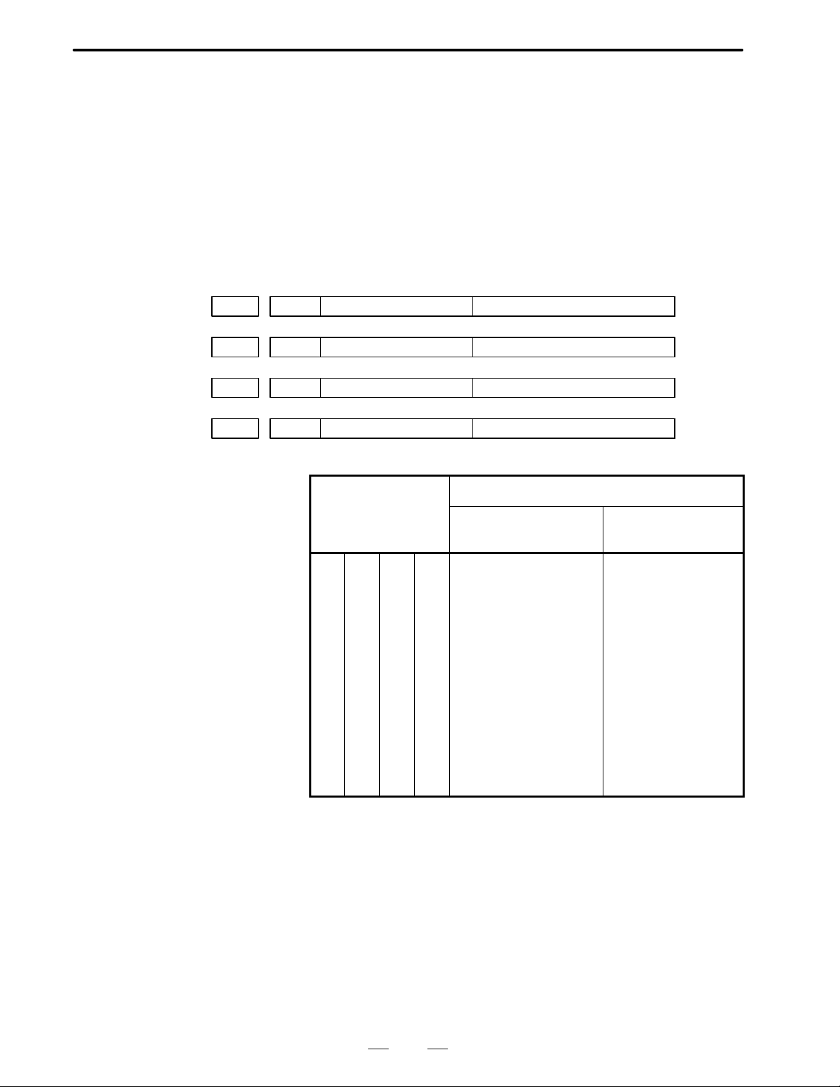
No. 0380#6 FODIC No. 0024#1 LII10 Input increment
0 0 IS–B
0 1 IS–A
1 0 IS–C
1 1 IS–B
[03. Cautions]
1) If a parameter with “POWER OFF” is rewritten, the P/S 000 alarm
(turn off the power) occurs. In this case, it is necessary to turn off the
power. This also applies when the programmable parameter input
(G10) function is used to rewrite the parameter.
2) Always set undefined parameter numbers/bits to 0.
21
Page 25

3. SETTING PARAMETER
SETTING PARAMETER
3
B–62580EN/01
[SETTING 1]
(1)REVX:
REVY: Specify whether to enable a mirror image for the X/Y–axis.
1: Enable
0: Disable
NOTE
If a mirror image is enabled for an axis, the movement of the
axis is reversed during automatic operation except for a
movement from the middle point to the reference position
for an automatic reference position return. The mirror image
function is ineffective during manual operation.
(2) TVON: Specifies whether to make a TV check when a program is
registered in memory.
1 : Makes a TV check.
0 : Does not make a TV check.
NOTE
1 The TV check (tape vertical parity check) function makes a
parity check for each block. This function issues an alarm
(P/S 002) if one block (from one EOB to the next EOB)
contains an odd number of characters.
2 Parameter No. 0018#6 (TVC) determines whether to make
a TV check on comments in a program.
(3) ISO: Specifies which code system is to be used in outputting a
program from memory.
1: ISO code
0: EIA code
NOTE
1 This parameter is valid under the following condition.
No. 0002#3 (I/O = 0), No. 0012#3 (I/O = 1), RSASCI = 0
2 An automatic decision is made on the code to be used in
registering programs in memory according to the first EOB
code.
LF: ISO code is assumed.
CR: EIA code is assumed.
22
Page 26

B–62580EN/01
3. SETTING PARAMETER
(4) INCH: Specifies the type of least input increment (input unit) for
programs.
1: Inch input
0: Metric input
NOTE
The least command increment (output unit) is specified by
No. 0001#0 (SCW).
(5)I/O: Specifies an input/output unit to be used on the reader/punch
interface.
0: Selects a unit on channel 1.
(Miscellaneous setting = No. 0002, I/O unit setting = No.
0038#6/7, baud rate = No. 0552)
1: Selects a unit on channel 1.
(Miscellaneous setting = No. 0012, I/O unit setting = No.
0038#6/7, baud rate = No. 0553)
(6) ABS: Specifies whether commands issued during the MDI mode
are absolute or incremental.
1: Absolute command
0: Incremental command
[SETTING 2]
NOTE
This parameter does not depend on G90/G91. (See
descriptions of No. 0029#5, or MABS.)
(7)SEQ: Specifies whether to insert sequence numbers automatically.
1: Automatic insertion
0: No automatic insertion
NOTE
No. 0550 specifies what increment is to be used in
automatic insertion.
(8)PWE: Specifies whether to enable parameter writing.
1: Enables.
0: Disables.
(9)REV4: Specifies whether to enable a mirror image for the fourth axis.
1: Enable
0: Disable
23
Page 27

4. DESCRIPTION OF P ARAMETERS
DESCRIPTION OF PARAMETERS
4
B–62580EN/01
POWER OFF
0001
PROD 1 : In the display of relative coordinate value, the programmed position is
RDRN 1 : Dry run is effective for rapid traverse.
#7
SCW 1 : Least command increment is input in inch system.
DCS 1 : Pushing the START button on the MDI panel directly actuate the
RS43 1 : Offset vector in G43, G44 remains in reset state.
IOF 1 : Offset value is input in absolute value.
DECI 1 : Decelaration signal “1” in refernce point return indicates
#6
RDRN#5DECI
(Machine tool: inch system )
0 : Least command increment is input in metric system.
(Machine tool:metric system)
If you want to change this parameter, turn off power.
displayed.
0 : In the display of relative coordinate value, the actual position
considering the offset is displayed
CNC start without going through the machine side (MDI mode only)
0 : Pushing the START button on the MDI panel issues the signal to the
machine side. The CNC start is actuated when the CNC receives the
start signal from machine side.
0 : Offset vector in G43, G44 is cleared in reset state.
0 : Offset value is input in incremental value.
deceleration.
0 : Decelaration signal “0” in refernce point return indicates
deceleration.
0 : Dry run is not effective for rapid traverse.
#4
IOF
#3
RS43#2DCS#1PROD#0SCW
#7
NFED0002
STP2 1 : In the reader/puncher interface, the stop bit is set by 2 bits.
PPD 1 : The relative coordinate value is preset when the coordinate system is
#6
TJHD#5PMXY2#4PMXY1#3RSASCI#2ASR33#1PPD#0STP2
0 : In the reader/puncher interface, the stop bit is set by 1 bit.
(Effective when the setting paramerter I/O is 0.)
NOTE
The band rate is set by parameter No.0552.
set.
0 : The relative coordinate value is not preset when the coordinate system
is set.
24
Page 28
B–62580EN/01
4. DESCRIPTION OF P ARAMETERS
ARS33 1 : The 20mA current interface is used as the reader/puncher interface.
0 : F ANUC PPR, F ANUC cassette, or portable tape reader are used as the
reader/punch interface. (Effective when the setting parameter I/O is
0.)
RSASCI 1 : ASCII code is used for reader/puncher interface.
0 : ISO/ EIA code is used for reader/puncher interface.
NOTE
This parameter is valid only when I/O on (SETTING 1) is set
to “0”.
PMXY2, 1 Set the tool escape direction in the fixed cycle G76 or G87.
The setting is as shown below according to the plane selection.
PMXY2 PMXY1 G17 G18 G19
0 0 +X +Z +Y
0 1 –X –Z –Y
TJHD 1 : Handle feed in the TEACH IN JOG mode by manual pulse generator
0 : Handle feed in the TEACH IN JOG mode by manual pulse generator
NFED 1 : Feed is not output before and after progtam is output by using the
0 : Feed is output before and after program is output by using the reader/
POWER OFF
0003
#7
ZMX, ZMY, ZMZ, ZM4
The reference point return direction and the backlash initial direction at
power on for X, Y, Z and 4th axes in order.
1 : Minus
0 : Plus
1 0 +Y +X +Z
1 1 –X –X –Z
is possible.
is not possible.
reader/puncher interface. (Set “1” for FANUC casette.)
puncher interface. (Effective when the seting parameter I/O is 0.)
#6
TLCP#5GST#4OVRI#3ZM4
#2
ZMZ
#1
ZMY#0ZMX
NOTE
The backlash compensation is initially performed when the
axis moves in the opposite direction against the direction
which is set by this parameter after the power is turned on.
OVRI 1 : When the polarity of override signal (*OV1 to +OV8, ROV1, ROV2)
is set to 1, the speed increases.
0 : When it is set to 0, the speed increases.
25
Page 29
4. DESCRIPTION OF P ARAMETERS
GST 1 : Gear shift is performed by SOR signal when S analog is outputted.
TLCP 1 : The tool length offset is performed in the axis direction being normal
B–62580EN/01
(Spindle speed is constant)
0 : Spindle orientation is performed by SOR signal when S analog is
outputted.
to the plane specified by plane selection (G17, G18, G19) (T ool length
offset B).
0 : The tool length offset is performed in the Z axis irrespective of plane
selection. (Tool length offset A).
POWER OFF
0004
POWER OFF
0005
POWER OFF
0006
POWER OFF
0007
#7
#7
#7
#7
#6 #5
DMRX
#6 #5
DMRY
#6 #5
DMRZ
#6 #5
DMR4
Setting code Capacity of reference counter
3 210
0
0
0
0
0
0
0
0
0
1
0
1
0
1
0
1
1
0
1
0
1
0
1
0
1
1
1
1
1
1
1
1
#4 #3 #2 #1 #0
GRDX
#4 #3 #2 #1 #0
GRDY
#4 #3 #2 #1 #0
GRDZ
#4 #3 #2 #1 #0
GRD4
GRDX to GRD4 Capacity of reference counter
Except for 0.1µ
detector for digital servo
0
0
0
1
1
0
1
1
0
0
0
1
1
0
1
1
0
0
0
1
1
0
1
1
0
0
0
1
1
0
1
1
1000
2000
3000
4000
5000
6000
7000
8000
9000
10000
1 1000
12000
13000
14000
15000
16000
0.1µ detector for
digital servo
10000
20000
30000
40000
50000
60000
70000
80000
90000
100000
1 10000
120000
130000
140000
150000
160000
26
Page 30
B–62580EN/01
4. DESCRIPTION OF P ARAMETERS
DMRX to DMR4 Setting of detective multiplier
Setting code Detective multiplier
#6 #5 #4 Digital servo
#7
EILK0008
ADW2, ADW1, ADW0
0
0
0
0
1
1
1
1
#6
OTZN#5ROVE#4ADW2#3ADW1#2ADW0
0
0
1
1
0
0
1
1
0
1
0
1
0
1
0
1
1 / 2
1
3 / 2
2
5 / 2
3
7 / 2
4
#1 #0POWER OFF
Name of the 4th axis
ADW2 ADW1 ADW0 Name
0 0 0 A
0 0 1 B
0 1 0 C
0 1 1 U
1 0 0 V
1 0 1 W
1 1 0 A
1 1 1 A
ROVE 1 : Rapid traverse override signal ROV2 is not effective. (100%, Fo)
0 : Rapid traverse override signal ROV2 is effective.
(100%, 50%, 25%, Fo)
OTZN 1 : Z axis stored strok check is not done.
0 : Z axis stored strok check is done.
EILK 1 : Interlock is performed for each axis.
(FANUC PMC–MODEL L is necessary.)
0 : Interlock is performed for all axes or for Z axis only
(it needs that No. 012 ZILK=1).
27
Page 31

4. DESCRIPTION OF P ARAMETERS
B–62580EN/01
#7
0009
#6 #5
TMF
#4 #3 #2 #1 #0
TFIN Time of reception width of FIN.
Setting range : 16 to 256 msec. (16 msec increment).
TMF Time from M, S, T code issue to MF, SF, TF issue.
Setting range : 16 to 256 msec. (16 msec increment).
TMF TFIN Parameter setting
16msec More then 16 msec 0 0 0 0
32msec More then 32 msec 0 0 0 1
48msec More then 48 msec 0 0 1 0
64msec More then 64 msec 0 0 1 1
80msec More then 80 msec 0 1 0 0
96msec More then 96 msec 0 1 0 1
1 12msec More then 112 msec 0 1 1 0
128msec More then 128 msec 0 1 1 1
144msec More then 144 msec 1 0 0 0
TFIN
160msec More then 160 msec 1 0 0 1
176msec More then 176 msec 1 0 1 0
192msec More then 192 msec 1 0 1 1
208msec More then 208 msec 1 1 0 0
224msec More then 224 msec 1 1 0 1
240msec More then 240 msec 1 1 1 0
256msec More then 256 msec 1 1 1 1
#7
APRS0010
#6 #5 #4
PRG9
#3 #2
OFFVY#1EBCL#0ISOT
ISOT 1 : Rapid traverse is effective even when reference point return is not
conducted after turning the power on.
0 : Rapid traverse is invalid unless refernce point return is conducted
after turning the power on.
EBCL 1 : In the display of the program stored in the memory, the EOB code is
indicated by *(asterrisk).
0 : In the desplay of the program stored in the memory , the EOB code is
indicated by; (semicolon).
OFFVY 1 : Servo alarm is not actuated when VRDY is on before PRDY is output.
0 : Servo alarm is acturated when VRDY is on before PRDY is output.
28
Page 32

B–62580EN/01
4. DESCRIPTION OF P ARAMETERS
PRG9 1 : The subprograms with program number 9000 to 9999 are protected.
The following edit function are disabled.
(1)Deletion of program
When the deletion of all program is specified, the programs with
programs number 9000 to 9999 are not deleted.
(2)Punch of program
These subprograms are not punched out when the punch of all
programs is specified.
(3)Program number search.
(4)Edit of program after registration
(5)Registration of program
Registration by MDI key and through paper tape.
(6)Collation
of program
(7)Display of program
0 : The subprograms with program number 9000 to 9999 can also be
edited.
APRS 1 : Automatic coordinate system setting is conducted
when manual reference point return is perfomed.
0 : Automatic coordinate system setting is not conducted.
POWER OFF
#7
MCINP0011
#6
G01#5SBKM#4MCF#3ADNW#2ADLN#1PML2#0PML1
PML2, 1 Pitch error compensation magnification. The value, with this
magnification multiplied to the set compensation value, is output
PML2
0 0 1
0 1 2
1 0 4
1 1 8
PML1
Magnification
(Common to all axes)
ADLN 1 : 4th axis is used as a linear axis.
0 : 4th axis is used as a rotary axis.
When 4th axis used as linear axis, there are following restrictions.
1) Circular interpolation including the 4th axis cannot be performed.
2) Cutter compensation B/C in the 4th axis cannot be applied.
3) Tool length compensation in the 4th axis cannot be applied.
ADNW 1 : Select B type for feed rate.
0 : Select A type for feed rate.
(A type)
(1)JOG feed rate
JOG feed rate of additional (rotary) axis is the same as that of basic
axes (X, Y, Z).
(2)Cutting feed upper limit feed rate
Tangential speed is clamped at parameter value for all axis.
29
Page 33

4. DESCRIPTION OF P ARAMETERS
MCF 1 : EF (external operation signal) is output when G81 positioning is not
B–62580EN/01
(B type)
(1)JOG feed rate
JOG feed rates of basic axes and additional axis can be set by
differnt parameter (No.565, 566). When an additional axis is
moved with another axis in simulteneously 2 or more axes control,
feed rate is the same as that of basic axes.
(2)Cutting feed upper limit feed rate
When command linear interpolation including additoional axis,
(G01), clamp each axis feed rate at smaller than the setting value
in another parameter (No.567). In circular interpolation, tangential
speed is clamped at parameter value. (Same as A Type)
(3)Minimum rapid traverse rate (Fo)
Only additional axis is set by another parameter. (No.0568)
(4)Low feedrate (FL) additonal axis at reference point return is set to
another parameter. (No.0569)
completed.
0 : EF (external operation signal) is not output when G81 positioning is
not completed.
SBKM 1 : Machine is stopped in single block skip by macro command.
0 : Machine is not stopped in single block skip by macro command.
G01 1 : G01 mode when power is on.
0 : G00 mode when power is on.
MCINP 1 : Program input is started with the data input external start signal
MINP.
0 : Program input is not started with the data input external start signal
MINP.
#7
NFED0012
#6
G84S#5FXCO#4FXCS#3RSASCI#2ASR33#1ZILK#0STP2
STP2 1 : In the reader/puncher interface, the stop bit is set by 2 bits.
0 : In the reader/puncher interface, the stop bit isset by 1 bit.
(Effective when the setting parameter I/O is 1.)
ZILK 1 : Interlock is effective only for Z axis.
0 : Interlock is effective for all axes.
Remarks Associated parameter is EILK at No.008.
ASR33 1 : The 20mA current interface is used as the reader/puncher interface.
0 : FANUC PRR, FANUC cassette, or portable tape reder are used as the
reader/puncher interface (Effective when the setting parameter I/O is 1.)
RSASCI 1 : ASCII code is used for reader/puncher interface.
0 : ISO/ EIA code is used for reader/puncher interface.
NOTE
This parameter is valid only when I/O on (SETTING 1) is set
to “1”.
30
Page 34

B–62580EN/01
4. DESCRIPTION OF P ARAMETERS
FXCS 1 : In canned cycle G74 or G84, spindle CW/CCW rotatioin is performed
without M05 code output.
0 : In canned cycle G74 or G84, spindle CW/CCW rotation is performed
after M05 signal output.
FXCO 1 : In canned cycle G76 and G87, the oriented spindle stop is performed
without outputting M05.
0 : In canned cycle G76 and G87, the oriented spindle stop is performed
after outputting M05.
G84S When a G74/G84 cycle is specified, gear switching is performed:
1 : At the gear switching points specified with parameters No. 0540 and
0556.
0 : At the gear switching points specified based on S analog output gear
switching type A or B.
NOTE
Whether S analog output gear switching function A or B is
used depends on the setting of bit 6 (LGCM) of parameter
No. 0035.
NFED 1 : Feed is not output before and after the program is output by using the
reader/puncher interface (Set to “1” when FANUC cassette is used.)
0 : Feed is output before and after the program is output by using the
reader/puncher interface. (Effective when the setting parameter I/O is 1.)
Remarks Baudrate is set by parameter No.0553.
#7
TCW0013
#6
CWM#5ORCW
#4 #3 #2 #1 #0
JHD 1 : The manual pulse generator is valid in JOG mode.
0 : The manual pulse generator is invalid in JOG mode.
ORCW 1 : Minus output in orientation S analog output.
0 : Plus output in orientation S analog output.
TCW, CWM Output code at S analog output.
TCW CWM Output code
0 0 Plus output for both M03 and M04
0 1 Minus output for both M03 and M04
1 0 Plus ouptut for M03, minus output for M04.
JHD
1 1 Minus output for M03, Plus output for M04
#7
0014
#6 #5 #4 #3 #2 #1 #0
SCTA
SCTA 1 : Spindle speed arrival signal (SAR) is always checked during cutting.
0 : Spindle speed arrival signal (SAR) is checked at the start of cutting.
31
Page 35

4. DESCRIPTION OF P ARAMETERS
B–62580EN/01
#7
CPRD0015
#6
REP#5PRWD#4LM2#3SKPF#2RILK
#1 #0
CBLNK
CBLNK 1 : The cursor does not blink.
0 : The cursor blinks.
RILK 1 : Interlock processing is done at high speed.
(FANUC PMC–MODEL L or M is necessary.)
0 : Normal interlock processing is done.
SKPF 1 : Dry run, override and automatic acceleration/deceleration is effective
in skip function (G31).
0 : Dry run, override and automatic acceleration/deceleration is
ineffective in skip function (G31).
LM2 1 : Makes valid stroke limit 2 switching signal (EXLM2 G129.6).
0 : Makes invalid stroke limit 2 switching signal (EXLM2, G129.6).
PRWD 1 : Rewind signal is output by portable tape reader.
0 : Rewind signal is not output by portable tape reader.
REP 1 : When the program with same program number in the memory is
registered through reader/puncher interface , the alarm does not occur
and the registered program is replaced.
0 : When the program with same program number in the memory is
registered through reader/puncher interface, the alarm occurs.
CPRD 1 : Unit is set to mm, inch or sec. when the decimal point is omitted in the
address for which the decimal point can be used.
0 : The least input increment is set when the decimal point is omitted in
the address for which the decimal point can be used.
#7
0016
#6 #5 #4 #3
NPRD#2SUPM
#1 #0
SUPM 1 : Start–up B type is effec–tive in cutter compensation C.
0 : Start–up A type is effective in cutter compensation C. For details of
start–up, refer to the item of cutter compensation.
NPRD 1 : Input and display with dicimal point is ineffective.
0 : Input and display with decimal point is effective.
#7
0017
#6
OPG7#5OPG6#4OPG5#3OPG4#2OPG3#1OPG2#0OPG1
OPG1 1 : Mode select (MD1 to MD4, ZRN) is conducted from the software
operator’s panel.
0 : Mode select is not conducted from the software operator’s panel.
NOTE
The above parameters are effective only when the optional
software operator’s panel is selected.
32
Page 36

B–62580EN/01
4. DESCRIPTION OF P ARAMETERS
OPG2 1 : Jog feed axis select and jog rapid traverse buttons are actuated with the
software operators’s panel.
0 : The above buttons are not actuated with the software operator’s panel.
OPG3 1 : Axis select (HX, HY, HZ) and magnification (10, 100) switches
for manual pulse generator are actuated with the software operator’s
panel.
0 : The above switches are not actuated with the software operator ’s
panel.
OPG4 1 : Jog feed rate, override, and rapid traverse override switches are
actuated with the software operator’s panel.
0 : The above switches are not actuated with the software operator ’s
panel.
OPG5 1 : Optional block skip, single block, machine lock and dry run switches
are actuated with the software operator’s panel.
0 : The above switches are not actuated with the software operator ’s
panel.
OPG6 1 : Pct key is actuated with the software operator’s panel .
0 : Protect key is not actuated with the software operator’s panel.
OPG7 1 : Feed hold is effected with the software operator’s panel.
0 : Feed hold is not effected with the software operator’s panel.
#7
EDITB0018
#6
TVC#5PROAD#4SQTYP#3NZMP4#2NZMP2#1NYMP2#0NXMP2
NXMP2, NYMP2, NZMP2, NZMP4
1 : Handle feed magnificaiton x100 is ineffective for X, Y, Z and 4th
axes, respectively.
0 : Handle feed magnification x100 is effective for X, Y, Z and 4th axis,
respectively .
NOTE
The magnification of an axis whose magnification x100 is
ineffective becomes x1 or x10 by singnal MP1.
MP1 = 1 : x 10
MP1 = 0 : x 1
SQTYP 1 : The program restart method should be R type. (not available)
0 : The program restart method should be P or Q type.
PROAD 1 : In the display of absolute coordinate value, the programmed position
is displayed.
0 : In the display of absolute coordinate value, the actualposition
considering the offset is displayed.
TVC 1 : No TV check at the comment.
0 : TV check at the comment.
EDITB 1 : Editing on standard keyboard shall be editing operation B.
0 : Editing operation shall be as specified in standard specifications.
33
Page 37

4. DESCRIPTION OF P ARAMETERS
B–62580EN/01
#7
DBCD0019
#6
NEOP#5M02NR#4SRGTP#3TLCD
#2 #1
C4NG
#0POWER OFF
C4NG 1 : 4th axis neglect signal is valid.
0 : 4th axis neglect signal is invalid.
TLCD 1 : Tool length compensation is the type C.
0 : Normal tool length compensation.
NOTE
When this parameter is set to 1, be sure to set OFRD (PRM
No. 36 bit6) to 1.
SRGTP 1 : G135.0 is used for the rigid tap selection signal
0 : G123.1 is used for the rigid tap selection signal.
M02NR 1 : Return to the head of program after executing M02.
0 : Do not return to the head of program after executing M02.
NEOP 1 : M02, M30 and M99 command the end of registration into part
program storage editing area.
0 : M02, M30 and M99 do not command the end of registration into part
program storage editing area.
DBCD 1 : In the diagnosis display, the timer counter data is displayed in
decimal.
0 : The diagnosis display is displayed in binary as usual.
#7
SFOUT0020
#6 #5
NCIPS#4BCD3
#3 #2 #1 #0
BCD3 1 : B code is 3–digit output.
0 : B code is 6–digit output.
NCIPS 1 : In deceleration, the control proceeds to the next block after the
specified speed has become zero. The control does not confirm that
the machine position meets a specified position.(No inposition
checking).
0 : The control proceeds to the next block after the specified speed has
become zero and confirms that the machine position has reached the
specified position in deceleration. (Inposition checking).
SFOUT 1 : SF is output in S4/5 digit even if gear change is not performed.
0 : SF is output in S4/5 digit on changing a gear.
POWER OFF
0021
#7
#6
NOFLUP
#5 #4 #3
APC4#2APCZ#1APCY#0APCX
APCX, Y, Z, 4 1 : When absolute pulse coder is optioned.
0 : When absolute pulse coder is not optioned.
NOFLUP When equipping absolute pulse coder,
1 : there is no coordinate running without axes motion at initial
power–up.
0 : there is coordinate running without axes motion at initial power–up.
34
Page 38

B–62580EN/01
4. DESCRIPTION OF P ARAMETERS
POWER OFF
0022
#7
#6 #5 #4 #3
ABS4#2ABSZ#1ABSY#0ABSX
ABSX, Y, Z, 4 1 : Reference point position in absolute pulse coder is settled.
0 : Reference point position in absolute pulse coder is not settled.
(It is automatically set to “1” when manualreference point return is
executed. Do not change the setting without changing the detector.)
#7
0023
#6
DSPN
#5 #4
DITA#3DCHI#2DFRN#1DGRM#0DJPN
DJPN CRT screen is displayed in Japanese.
DGRM CRT screen is displayed in German.
DFRN CRT screen is displayed in French.
DCHI CRT screen is displayed in Chinese (Formosan).
DITA CRT screen is displayed in Italian
DSPN CRT screen is displayed in Spanish.
#7
0024
#6
CLCL
#5 #4 #3 #2
SCTO#1LII10#0IGNPMC
IGNPMC 1 : Control by PMC is made ineffective. (Same as without PMC.)
0 : Control by PMC is made effective.
LII10 1 : Inputting/Outputting unit is 0.01mm/0.01deg/0.001 inch.
0 : Inputting/Outputting unit is 0.001mm/0.001deg/0.0001 inch (Usual)
SCTO 1 : Spindle speed reach signal is checked.
0 : Spindle speed reach signal is not checked.
CLCL 1 : The local coordinate system is canceled by automatic reference point
return.
0 : Not canceled.
#7
PSG20028
#6
PSG1#5EX10D#4EXTS
#3 #2
DACTF#1PRGMSG#0PRCPOS
PRCPOS 1 : On the program check screen, the absolute coordinates are displayed.
0 : The relative coordinates are displayed.
PRCMSG 1 : On the program check screen, a message from PMC is displayed.
(not available)
0 : The remaining motion is displayed.
DACTF 1 : Actual speed is displayed on the current positon display screen and
program check screen.
0 : Not displayed.
EXTS 1 : External program number search is valid.
0 : External program number search is invalid.
EX10D 1 : External work coordinate system shift function: 10 times the input
value corresponds to the external work zero point offset value.
0 : The input value corresponds to the external work zero point offset
value.
35
Page 39

4. DESCRIPTION OF P ARAMETERS
PSG1, 2 Gear ratio of spindle and position coder
Scale =
B–62580EN/01
Spindle speed
Position coder speed
Scale PSG2 PSG1
1 0 0
2 0 1
4 1 0
8 1 1
#7
0029
#6 #5 #4 #3
G604#2G60Z#1G60Y#0G60X
G60X to 4 Specify the approach direction in the single direction positioning of
X–axis, Y–axis, Z–axis and 4th axis in sequence.
1 : Minus direction
0 : Plus direction
POWER OFF
#7
G910030
#6
AXS4D
#5 #4 #3 #2
OFCDH#1EAC1#0EAC0
EAC0, EAC1 Axis setting for PMC axis control
EAC1 EAC0 Controlled axis
0
0
1
1
0
1
0
1
4th axis
X axis
Y axis
Z axis
OFCDH 1 : Tool offset memory C is used.
0 : Tool offset memory C is not used.
NOTE
It is necessary to set parameter 036#6 (OFRD) to “1” when
this parameter is set to “1”.
AXS4D 1 : 4th–axis name is displayed depending on parameter 280.
0 : 4th–axis name depends on parameter 008 ADW0, ADW1 and
ADW2.
G91 1 : When the power is turned on, G91 mode is set.
0 : When the power is turned on, G90 mode is set.
#7
0032
#6
EACSB
#5 #4
PNGMLK
#3 #2 #1 #0POWER OFF
PNGMLK 1 : In PMC axis control, machine lock shall be invalid.
0 : In PMC axis control, machine lock shall be valid.
EACSB 1 : PMC axis control is of the B specification.
0 : PMC axis control is of the A specification.
36
Page 40

B–62580EN/01
4. DESCRIPTION OF P ARAMETERS
#7
ACMR0035
#6
LGCM#5RGCTO
#4 #3
NDSP4#2NDSPZ#1NDSPY#0NDSPX
NDSPX, Y, Z, 4 Whether the current positions of X, Y , Z and 4th axes are displayed or not
1 : The current position is not displayed.
0 : The current position is displayed.
RGCTO When using rigid tapping,
1 : time constant during pulling out spindle is different from that of
tapping.
(Time constants are set in parameter 400, 401 and 402.)
0 : time constant during pulling out spindle is same as that of tapping.
LGCM The motor speeds used for gear switching are:
1 : Those specified with parameters No. 0585 and 0586 (gear switching
type B).
0 : The maximum motor speed for each gear (gear switching type A).
ACMR 1 : Optional CMR is used.
0 : Optional CMR is not used.
#7
0036
#6
OFRD#5TLCDOK
#4 #3 #2 #1 #0
TLCDOK 1 : An alarm is not given even if more than two axes are offset in the tool
length compensation of type C.
0 : An alarm is given when more than two axes are offset in the tool
length compensation of type C.
OFRD 1 : Tool length compensation is specified by H–code, and cutter
compensation is specified by D–code.
0 : Tool length compensation and cutter compensation are specified by
H–code as usual.
37
Page 41

4. DESCRIPTION OF P ARAMETERS
B–62580EN/01
POWER OFF
#7
PLC010037
#6
VALT
#5 #4 #3
SPTP4#2SPTPZ#1SPTPY#0SPTPX
SPTPX to SPTP4 T ypes of position detector of the X, Y, Z and to the 4th axis in this order.
1 : The separate type pulse coder is to be used as a detector.
0 : The separate type pulse coder is not to be used as a detector.
In case of the 0–GSD with 0.1µ pulse coder, set the following parameters
in units of 1µ. (The set data is multiplied by ten within the CNC)
No. Parameter
0504 SERRX (X) Limitation value of position deviation amount during
0505 SERRT (Z) Limitation value of position deviation amount during
0506 SERRZ (3) Limitation value of position deviation amount during
0507 SERRZ4 (4) Limitation value of position deviation amount during
0508 GRDSX (X) Grid shift amount of the X – axis.
0509 GRSDY (Z) Grid shift amount of the Y – axis.
*
movement of X axis.
movement of Y axis.
movement of Z axis.
movement of 4th axis.
Contents
0510 GRDSZ (3) Grid shift amount of the Z – axis.
0511 GRDS4 (4) Grid shift amount of the 4th axis.
NOTE
Above explanation is applied when the parameter “PLC01”
(No. 0037 bit 7) = 1
VALT 1 :Time constant is steplessly switched in rigid tapping.
0 : Time constant is not steplessly switched in rigid tapping.
NOTE
In the case of stepless switching of time constant, specify
the gear to make tapping by using the S–analog output type
B (parameter No.12 G84S=1) if the gear is one stage or
more stages. Don’t use it in the system in which tapping is
made over several stages of gear.
PLC01 1 : A pulse coder of 0.1µ detection is to be used.
0 : A pulse coder of 0.1µ detection is not to be used.
38
Page 42

B–62580EN/01
4. DESCRIPTION OF P ARAMETERS
#7
RSCMD10038
RSCMD1, DEVFL 1
#7
LOCC0040
NAMPR 1 : Displays the program name on the directory display screen.
DPOSUP 1 : At data output by DPRINT command, a space is outputted for reading
#6
DEVFL1
#5 #4 #3 #2 #1 #0POWER OFF
Setting I/O device of reader/puncher interface channel 1.
RSCMD DEVFL1 I/O device used
0 0 Bubble cassette
0 1 Floppy cassette
1 0 RS232, PPR
1 1 New interface
#6
COMC#5TMCR#4SORT#3RWCNT#2RGTPE#1DPOSUP#0NAMPR
0 : Does not display the program name on the program directory display
screen.
zero.
0 : At data output by DPRINT command, nothing is done for reading
zero.
RGTPE When releasing rigid tapping mode,
1 : rigid tapping signal (RGTAP/RGTPN) off is not checked.
0 : rigid tapping signal (RGTAP/RGTPN) off is checked.
RWCNT 1 : Does not count the total number of parts machinedand the number of
parts machined even when M02/M30 are executed.
0 : Counts the total number of parts machined and the number of parts
machined each time M02/M30 are executed.
SORT 1 : At the display of program library, it is displayed in numerical order.
0 : Program library is displayed in normal specification.
TMCR 1 : T code calling subprogram O9000
0 : T code as a normal tool function
COMC 1 : Does not place common variables (#100 to 149) in <vacant> state
during resetting.
0 : Places common variables (#100 to 149) in <vacant> state during
resetting.
LOCC 1 : Does not place local variables (#1 to 33) in <vacant> state during
resetting.
0 : Places local variables (#1 to 33) in <vacant> state during resetting.
#7
0042
#6 #5 #4 #3 #2 #1 #0
ASTCD
ASTCD Specifies the hole pattern for the EIA code corresponding to symbol *,
using 8 bits, for custom macro B.
39
Page 43

4. DESCRIPTION OF P ARAMETERS
B–62580EN/01
#7
0043
#6 #5 #4 #3 #2 #1 #0
EQCD
EQCD Specifies the hole pattern for the EIA code corresponding to symbol =,
using 8 bits, for custom macro B.
#7
0044
#6 #5 #4 #3 #2 #1 #0
SHPCD
SHPCD Specifies the hole pattern for the EIA code corresponding to symbol #,
using 8 bits, for custom macro B.
#7
HSIF0045
#6
CLER
#5 #4
CCINP
#3 #2
RWDOUT#1RAL
#0
RDL
RDL 1 : Registers a program after all programs are erased for reading for I/O
device external control.
0 : The reading is the same as in normal specification for I/O device
external control.
RAL 1 : Registers only one program for reading through reader/puncher
interface.
0 : Registers all programs for reading through reader/puncher interface.
RWDOUT 1 : No signal is outputted in rewinding.
0 : A signal is outputted in rewinding.
CCINP 1 : The in–position width for cutting feed is specified with different
parameters from those used for rapid traverse (No.0609 to 0612).
0 : The in–position width for cutting feed is specified with the same
parameters as those used for rapid traverse (No.0500 to 0503).
CLER 1 : Selects clear conditions, using the reset button,external reset signal
and emergency stop.
0 : Selects reset conditions, using the reset button, external signal and
emergency stop.
HSIF 1 : M/S/T/B code processing shall be a high–speed interface.
0 : M/S/T/B code processing shall be a normal interface.
#7
SFFDSP0048
#6 #5 #4
SMZCT
#3 #2 #1 #0
SMZCT 1 : Rapid traverse block overlap is used.
0 : Rapid traverse block overlap is not used.
SFFDSP 1 : Soft–key is displayed regardless of equipping options.
0 : Whether soft–key is displayed or not depends on equipping options.
#7
FML100049
#6
NPRV#5EFML10#4S3JOG
#3 #2 #1
RDIK#0DILK
DILK 1 : The each axis interlock signal shall be valid, only in manual
operation.
0 : The each axis interlock signal shall be invalid
40
.
Page 44

B–62580EN/01
4. DESCRIPTION OF P ARAMETERS
RDIK 1 : The high–speed interlock signal shall be invalid when the each axis
interlock signal goes off.
0 : The high–speed interlock signal shall be always valid.
S3JOG 1 : The number of simultaneously controlled axes in manual operation is
3 maximum.
0 : The number of simultaneously controlled axes in manual operation is
1 maximum.
EFML10 1 : The feedrate command (cutting feed) of PMC axis control is used by
10 times.
0 : Standard specification.
NPRV 1 : Even when no position coder is provided, the per–revolution feed
command shall be valid. (The per–revolution feed command is
converted automatically to the per–minute feed in CNC.)
0 : When no position coder is provided, the per–revolution feed
command shall be invalid.
FML10 1 : The rapid traverse rate and cutting feed upper limit speed parameter
increment system shall be 10 mm/min or 1 inch/min.
e.g) For 100 m/min, the setting value shall be 10000.
0 : As per normal specifications.
NOTE
If the 1/10 increment system function is used, this
parameter is invalid and must be set to 0.
#7
0050
#6 #5 #4 #3 #2 #1
NOFMK
#0
NOFMK 1 : Tape format check is not done during sequence No. search.
0 : Tape format check is done during sequence No. search.
#7
0052
#6 #5 #4 #3
NODIC4
#2 #1 #0
NODIC4 1 : The current position display of PMC axis control shall be the same as
in standard specifications, not in accordance with the decimal point
position of increment system 1/10.
0 : The current position display of PMC axis control is in accordance
with the decimal point position of increment system 1/10.
#7
0053
#6 #5 #4 #3
LBLCD
#2 #1 #0
#7
0054
#6 #5 #4 #3
RBLCD
#2 #1 #0
LBLCD/RBLCD The hole pattern of and in EIA code in custom macro B is set by 8–bit data
in sequence.
41
Page 45

4. DESCRIPTION OF P ARAMETERS
B–62580EN/01
#7
0056
#6 #5 #4 #3 #2 #1 #0
NOCND
NOCND When equipping tape storage memory 120/ 320m or back–ground edit,
1 : condensing part program memory is not automatically done.
(Condensing is done by pressing soft–key “CONDNS”.)
0 : condensing part program memory is automatically done by CNC
reset after edit operation.)
#7
0057
#6
FXY#5HOT3#4CROUT#3MIC
#2 #1 #0
MIC 1 : At omission of decimal point, the minimum set unit is multiplied by
ten.
0 : At omission of decimal point, the minimum set unit is notmultiplied
by ten.
CROUT In B/D PRINT, after the data is outputted in ISO code:
1 : “LF” and “CR” are outputted.
0 : Only the “LF” is outputted.
HOT3 1 : Signals (X020#0
0 : Signals (X020#0
+LX to *–LZ) of hardware OT is valid.
*
+LX to *–LZ) of hardware OT is invalid.
*
FXY 1 : The drilling axis in a fixed cycle is the axis selected by a program.
0 : The drilling axis in a fixed cycle is usually Z–axis.
POWER OFF
0060
#7
#6
EXTSP#5OPMNDP#4HDLPM
#3 #2
LDDSPG#1PCLDB#0DADRDP
DADRDP 1 : Addresses X, Y, G, F, R and D are displayed on DGN screen.
0 : Addresses X, Y, G, F, R and D are not displayed on DGN screen.
PCLDB 1 : Baud rate for ladder program loading is 9600.
0 : Baud rate for ladder program loading is 4800.
LDDSPG 1 : Ladder dynamic display is valid.
0 : Ladder dynamic display is invalid.
HDLPM When manual pulse generator is rotated rapidly,
1 : movements always coincide with rotated amounts.
0 : movements happens not to coincide with rotated amounts by
clamping with rapid traverse rate.
OPMNDP 1 : Operating monitor display is valid.
0 : Operating monitor display is invalid.
EXTSP 1 : Program No. search and display are valid for the protected part
programs by parameter PRG9.
0 : Program No. search and display are inhibited for the protected part
programs by parameter PRG9.
42
Page 46

B–62580EN/01
4. DESCRIPTION OF P ARAMETERS
#7
0061
#6 #5 #4 #3
EBC4#2EBCZ#1EBCY#0EBCX
EBCX to EBC4 1 : B is used for DI/DO of PMC axis control.
0 : A is used for DI/DO of PMC axis control.
#7
0062
#6
AXPCF
#5 #4 #3
SPMRPM#2G40V
#1 #0POWER OFF
G40V When G40, G41 and G42 are commanded without motion,
1 : offset motion is vertical to the next start movement in case of start–up
or it is vertical to the previous end movement in case of cancelling.
0 : offset motion is as described in operator’s manual.
SPMRPM 1 : Unit of parameters related to the spindle rotation speed is 10 rpm.
0 : Unit of parameters related to the spindle rotation speed is 1 rpm.
NOTE
When setting this parameter, setting unit of parameter 0539,
0540, 0541, 0542 ,0543, 0551, 0555 and 0556 is 10rpm.
AXPCF 1 : Axes movement by PMC axis control is not added in actual speed
display.
0 : Axes movement by PMC axis control is added in actual speed display .
#7
0063
#6 #5
EAXOV#4RGDOV#3VALPC
#2 #1
PRSTIN#0MTDSPI
MTDSPI 1 : Machine coordinate system is displayed to meet the input system.
0 : Machine coordinate system is not displayed to meet the input system.
PRSTIN 1 : When the input is of the inch system, automatic coordinate system
setting is handled as a separate parameter.
0 : When the input is of the inch system, automatic coordinate system
setting is not handled as a separate parameter.
VALPC 1 : Optional gear ratio is used between the spindle and the position coder
in rigid tapping.
0 : Optional gear ratio is not used between the spindle and the position
coder in rigid tapping.
NOTE
When VALPC = 1, the optional gear ratio between the
spindle and the position coder is set in parameters No. 259
–264. When V ALPC = 0, the gear ratio between the spindle
and the position coder is set in the parameter No. 28.
RGDOV 1 : Override is valid in drawing in rigid tapping.
0 : Override is invalid in drawing in rigid tapping.
43
Page 47

4. DESCRIPTION OF P ARAMETERS
EAXOV 1 : Dry run and override is valid for the PMC axis.
B–62580EN/01
NOTE
Override value is specified by the parameter No. 258
(RGOVR).
0 : Dry run and override is invalid for the PMC axis.
#7
0064
#6 #5
NPA
#4 #3 #2 #1
ALLPRE#0SETREL
SETREL 1 : Preset is made for each axis in the relative position display.
0 : Preset is as usual.
ALLPRE 1 : Origin setting of relative coordinates is performed by numeric key.
0 : Origin setting of relative coordinates is performed by address key.
NPA 1 : The screen is not switched to the alarm/message screen at occurrence
of alarm or at the entry of operator message.
0 : The screen is switched to the alarm/message screen at occurrence of
alarm or at the entry of operator message.
#7
M3B0065
#6 #5
TAPDRN
#4 #3
PSOT
#2 #1 #0
PSOT 1 : Stored stroke check is ignored until reference point return is finished
after CNC power–up.
0 : Stored stroke check is valid just after CNC power–up.
TAPDRN 1 : Dry–run is ignored for tapping cycle (G74, G84).
0 : Dry–run is valid for tapping cycle (G74, G84).
M3B 1 : Maximum 3M codes can be disignated in one block.
2 : M–code designations in one block are as usual.
#7
0066
#6 #5 #4 #3
EPMSKP
#2 #1 #0POWER OFF
EPMSKP 1 : Skip signal for PMC axis control is independent of CNC skip signal.
0 : Skip signal for PMC axis control is same as CNC skip signal.
#7
ICR0070
#6
PEXRD
#5 #4
DSTBGE
#3 #2 #1 #0
DSTBGE 1 : “DST” is not output when pressing ST AR T key in background edit in
order to punch out part programs.
0 : “DST” is output always when pressing START key.
PEXRD 1 : Expanded R/D data on PMC–M is used.
0 : Expanded R/D data on PMC–M is not used.
ICR 1 : EOB is punched out as “LF” when punching with ISO code.
0 : EOB is punched out as “LF” “CR” “CR” when punching with ISO
code.
44
Page 48

B–62580EN/01
4. DESCRIPTION OF P ARAMETERS
POWER OFF
#7
FSRSP0071
#6
DPCRAM
#5 #4
SRL2SP
#3 #2 #1 #0
ISRLPC
ISRLPC 1 : Position coder cable is connected to M27 on memory PCB when
using serial interface spindle.
0 : Position coder cable is connected to spindle amplifier when using
serial interface spindle.
SRL2SP 1 : Two serial interface spindles are connected serially.
0 : One serial interface spindle is connected.
DPCRAM 1 : PMC starts automatically at power–up when using PMC RAM board.
0 : “PMC LOAD MENU” is displayed at power–up when using PMC
RAM board.
FSRSP 1 : Serial interface spindles are used.
0 : Serial interface spindles are not used.
#7
0074
#6 #5 #4 #3
CRF4#2CRFZ#1CRFY#0CRFX
CRFX When the motion other than G28 is commanded for X–axis whose
machine coordinate is not fixed yet,
1 : alarm 224 appears.
0 : no alarm appears.
CRFY When the motion other than G28 is commanded for Y–axis whose
machine coordinate is not fixed yet,
1 : alarm 224 appears.
0 : no alarm appears.
CRFZ When the motion other than G28 is commanded for Z–axis whose
machine coordinate is not fixed yet,
1 : alarm 224 appears.
0 : no alarm appears.
CRF4 When the motion other than G28 is commanded for 4th–axis whose
machine coordinate is not fixed yet,
1 : alarm 224 appears.
0 : no alarm appears.
#7
IONUL0075
#6 #5 #4 #3 #2 #1 #0
IONUL 1 : Alarm appears when detecting a null code in reading EIA code.
0 : No alarm appears when detecting a null code in reading EIA code.
#7
OTRFOM0076
#6 #5 #4
ADBLS#3G84RGD#2IOP#1JZRN#0ERDT
ERDT 1 : Error detect function is effective.
0 : Error detect function is ineffective.
JZRN 1 : Dogless reference point return is effective. (Note)
0 : Dogless reference point return is ineffective.
45
Page 49

4. DESCRIPTION OF P ARAMETERS
IOP 1 : Soft–key “STOP” interrupts reading/punching.
G84RGD 1 : M29 is not necessary for shifting rigid tapping mode.
ADBLS 1 : Cutting feed and rapid traverse separate backlash compensation is
B–62580EN/01
NOTE
This parameter is applied to all axes. To set each axis
individually, set this parameter to 1, then set bits 0 to 5 of
parameter No. 0391 as required.
(Reset operation does not stop reading/punching.)
0 : Reset operation stops reading/punching.
0 : M29 is necessary for shifting rigid tapping mode.
valid.
0 : Cutting feed and rapid traverse separate backlash compensation is
invalid.
NOTE
The backlash compensation values for rapid traverse are
specified with parameters No. 0686 to 0691.
OTRFOM 1 : Stored stroke limit alarm appears just before exceeding it.
0 : Stored stroke limit alarm appears just after exceeding it.
#7
0077
#6
HLKEY
#5 #4 #3 #2 #1
CT3G
#0POWER OFF
CT3G 1 : Time constant on rigid tapping is changing according to gear
selection.
0 : Time constant on rigid tapping is fixed although gear selection
changes.
HLKEY 1 : MDI key operation is treated with high priority.
0 : MDI key operation is treated with normal priority.
#7
EAXOVE0078
#6
RDRNE
#5 #4
OVRIE#3NOINWZ#2NOINMV
#1 #0
NOINOW
NOINOW 1 : Changing offset values by using MDI key is prohibited.
0 : Changing offset values by using MDI key is allowed.
NOINMV 1 : Changing macro variables by using MDI key is prohibited.
0 : Changing macro variables by using MDI key is allowed.
NOINWZ 1 : Changing work zero offset values by using MDI key is prohibited.
0 : Changing work zero offset values by using MDI key is allowed.
OVRIE 1 : The logic of override signals for PMC axis control is that “1” means
high speed.
0 : The logic of override signals for PMC axis control is that “1” means
low speed.
46
Page 50

B–62580EN/01
4. DESCRIPTION OF P ARAMETERS
NOTE
This parameter is effective only when parameter 078#7
(EAXOVE) is set to “1”.
RDRNE 1 : Dry–run signals is effective for rapid traverse of PMC axis control.
0 : Dry–run signals is ineffective for rapid traverse of PMC axis control.
NOTE
This parameter is effective only when parameter 078#7
(EAXOVE) is set to “1”.
EAXOVE 1 : Dry–run and over–ride signals of PMC axis control are different from
CNC axis control.
0 : Dry–run and over–ride signals of PMC axis control are same as CNC
axis control.
#7
0080
#6 #5 #4 #3 #2
MORCM1 1 : Spindle orientation whose position is specified from PMC is used for
1st serial interface spindle.
0 : Spindle orientation whose position is specified from PMC is not used
for 1st serial interface spindle.
POWER OFF
0100 CMRX
0101 CMRY
0102 CMRZ
0103 CMR4
CMRX, CMRY, CMRZ, CMR4
Command multiply for X, Y, Z and 4th axes, respectively.
#1 #0POWER OFF
MORCM1
Setting code Multiplier
1 0.5
2 1
4 2
10 5
20 10
When an arbitrary command multiply (No. 0035 ACMR=1) is used, there
are 2 types of setting methods as follows.
(1)When a command multiply is 1/2 to 1/27:
Preset value =
1
+ 100
Command multiply
47
Page 51

4. DESCRIPTION OF P ARAMETERS
0108 SPLOW
SPLOW Spindle speed during constant speed spindle rotation, or spindle speed at
B–62580EN/01
(2)When a command multiply is 2 to 48 :
Preset value = 2 (Command multiply)
NOTE
1 For (2) above, be sure to set a value such that the command
multiply should be always an integer.
2 Set the backlash compensation and pitch error
compensation values with detection unit when an arbitrary
command multiply is used.
gear shift. (when parameter No. 0003, GST=1),
Setting value =
Spindle motor speed at gear shift
4095
Max. motor speed
[Setting value] 0 to 255 (unit : rpm (10rpm at parameter No.0062#3=1))
0110 SCTTIM
SCTTIM Set the delay timer for checking the spindle speed reach signal. This sets
the time required from execution of the S function to the beginning of
checking the spindle speed reach signal.
[Setting value] 0 to 255 (unit: msec)
Spindle speed
reach signal
S command
Delay timer
SCTTIM
Pulse distribution
0111 MBUF1
0112 MBUF2
MBUF1, 2 Up to two M codes which are not subjected to buffering for the next block
can be set.When 03 is set, M03 is not subjected to buffering for the next
block.
48
Page 52

B–62580EN/01
4. DESCRIPTION OF P ARAMETERS
0121 MULHPG
MULHPG Multiplier n of the manual handle feed.
[Setting value] 1 – 127
Multiplier n when selection signal MP2 for the manual hand feed move
distance in on, set to 100 as a standard value.
0130 UPKY
0131 DWNKY
0132 RGTKY
0133 LFTKY
0134 FWDKY
0135 BACKY
0136 RTDKY
0137 LTULY
URKY to LTUKY Set the jog feed axes and directions on the software operator ’s panel
corresponding to °, ±, ³, ², ¼, ½, and keys.
Axis/Direction Setting Value
+X 1
–X 2
+Y 3
–Y 4
+Z 5
–Z 6
+4 7
–4 8
Example)
When setting ° to +X, ± to –X, ³ to +Z and ² to –Z, set as follows.
UPKY=5, DWNKY=6, RGTKY=1, LFTKY=2, FWDKY=4,
BACKY=3.
49
Page 53

4. DESCRIPTION OF P ARAMETERS
0140 NSW11
0203 NSW88
B–62580EN/01
The names of general purpose switches (SIGNAL 0 – SIGNAL 7) on the
software operator’s panel in the following figure are set as follows.
OPERATOR’S P ANEL O1234 N5678
SIGNAL0 : OFF ON
SIGNAL1 : OFF ON
SIGNAL2 : OFF ON
SIGNAL3 : OFF ON
SIGNAL4 : OFF ON
SIGNAL5 : OFF ON
SIGNAL6 : OFF ON
SIGNAL7 : OFF ON
AUTO
50
Page 54

B–62580EN/01
4. DESCRIPTION OF P ARAMETERS
Characters are set by codes in parameters 0140 to 0203 as follows:
PRM. No. 140
Code (083) corresponding to character “S” of SIGNAL in the above
figure is set.
PRM. No. 141
Code (073) corresponding to character “I” of SIGNAL 0 in the above
figure is set.
PRM. No. 142
Code (071) corresponding to character “G” of SIGNAL 0 in the above
figure is set.
PRM. No. 143
Code (078) corresponding to character “N” of SIGNAL 0 in the above
figure is set.
PRM. No. 144
Code (065) corresponding to character “A” of SIGNAL 0 in the above
figure is set.
PRM. No. 145
Code (076) corresponding to character “L” of SIGNAL 0 in the above
figure is set.
PRM. No. 146
Code (032) corresponding to character “ ”(space) of SIGNAL 0 in the
above figure is set.
PRM. No. 147
Code (048) corresponding to character “0” of SIGNAL 0 in the above
figure is set.
PRM. No. 0148–0155
Characters corresponding to SIGNAL 1 in the above figure.
PRM. No. 0156–0163
Characters corresponding to SIGNAL 2 in the above figure.
PRM. No. 0164–0171
Characters corresponding to SIGNAL 3 in the above figure.
PRM. No. 0172–0179
Characters corresponding to SIGNAL 4 in the above figure.
PRM. No. 0180–0187
Characters corre–sponding to SIGNAL 5 in the above figure.
PRM. No. 0188–0195
Characters corresponding to SIGNAL 6 in the above figure.
PRM. No. 0196–0203
Characters corre–sponding to SIGNAL 7 in the above figure.
For character codes, refer to the characters–to–codes table in the next page.
Setting value 0 is a space.
51
Page 55

4. DESCRIPTION OF P ARAMETERS
B–62580EN/01
Character–to–codes correspondence table
Character Code Comment Character Code Comment
A 065 6 054
B 066 7 055
C 067 8 056
D 068 9 057
E 069 032 Space
F 070 ! 033 Exclamation mark
G 071 ” 034 Quotation mark
H 072 # 035 Sharp
I 073 $ 036 Dollar symbol
J 074 % 037 Percent
K 075 & 038 Ampersand
L 076 ’ 039 Apostrophe
M 077 ( 040 Left parenthesis
N 078 ) 041 Right parenthesis
O 079 * 042 Asterrisk
P 080 + 043 Plus sign
Q 081 , 044 Comma
R 082 – 045 Minus sign
S 083 . 046 Period
T 084 / 047 Slash
U 085 : 058 Colon
V 086 ; 059 Semi – colon
W 087 < 060 Left angle bracket
X 088 = 061 Sign of equality
Y 089 > 062 Right angle bracket
Z 090 ? 063 Question mark
0 048 @ 064 Commercial at mark
1 049 [ 091 Left square bracket
2 050 ^ 092
3 051 ¥ 093 Yen symbol
4 052 ] 094 Right square bracket
5 053 _ 095 Underline
52
Page 56

B–62580EN/01
4. DESCRIPTION OF P ARAMETERS
0204 POSTN1
0205 POSTN2
0206 POSTN3
0207 POSTN4
POSTN1 to 4 Approach amount for single direction positioning of X–axis, Y–axis,
Z–axis and 4th axis
[Setting value] 0 to 255
[Unit] 0.01 mm (metric output)
0.001 inch (inch output)
NOTE
In increment system 1/10, the unit is the same as above.
But the Max. value is 163.
0212 INTPLN
INTPLN 0 : G17 is selected with power on.
1 : G18 is selected with power on.
2 : G19 is selected with power on.
0219 MCDCNT
MCDCNT When the preset M code is executed, the total number of machined parts
and the number of machined parts are counted.
[Setting value] 1 to 255
(0 is equivalent to no setting.98 and 99 cannot be set.)
0220 UMGCD0
0229 UMGCD9
Set up to 10 G codes calling custom macro.
UMGCD0 G code calling custom macro body O9010
UMGCD1 G code calling custom macro body O9011
UMGCD2 G code calling custom macro body O9012
UMGCD3 G code calling custom macro body O9013
UMGCD4 G code calling custom macro body O9014
UMGCD5 G code calling custom macro body 09015
UMGCD6 G code calling custom macro body O9016
53
Page 57

4. DESCRIPTION OF P ARAMETERS
UMGCD7 G code calling custom macro body O9017
UMGCD8 G code calling custom macro body O9018
UMGCD9 G code calling custom macro body O9019
[Setting value] 001 to 225
0230 UMMCD4
0239 UMMCD13
UMMCD4 M code calling custom macro body O9020
UMMCD5 M code calling custom macro body O9021
UMMCD6 M code calling custom macro body O9022
B–62580EN/01
(With M00, no custom macro can be called. Even when 0 is set, it is
equivalent to no setting.)
Set up to 10 M codes calling custom macro.
UMMCD7 M code calling custom macro body O9023
UMMCD8 M code calling custom macro body O9024
UMMCD9 M code calling custom macro body O9025
UMMCD10 M code calling custom macro body O9026
UMMCD11 M code calling custom macro body O9027
UMMCD12 M code calling custom macro body O9028
UMMCD13 M code calling custom macro body O9029
[Setting value] 006 to 255
(With M00, no custom macro can be called. Even when 0 is set, it is
equivalent to no setting.)
240 UMMCD1
241 UMMCD2
242 UMMCD3
Set up to 3 M codes calling sub program.
UMMCD1 M code calling sub program body O9001
UMMCD2 M code calling sub program body O9002
UMMCD3 M code calling sub program body O9003
[Setting value] 003 to 255
(With M00, no sub program can be called. Even when 0 is set, it is
equivalent to no setting.)
54
Page 58

B–62580EN/01
4. DESCRIPTION OF P ARAMETERS
0252 PRSTCT
PRSTCT Set this parameter to prolong the RST signal output time. The time is set
by the parameter in units of 16 msec.
(RST signal output time) = (Reset time) + (Parameter value) 16 msec
[Setting value] 0 to 255
0254 TPSUP
TPSUP Spindle and Z–axis acceleration/deceleration type in the rigid tapping.
[Data type] Byte
[Setting value] 0 : Exponential acceleration/ deceleration
1 : Linear acceleration/deceleration
[Standard set value] 0
0255 BKL9
BKL9 Spindle backlash amount in the rigid tapping mode
[Data type] Byte
[Setting value] 0 to 127
[Unit] Detection unit
0256 MCODE
MCODE M–code to specify the rigid tapping mode
[Data type] Byte
[Setting value] 0 to 256
NOTE
When 0 is set, regard as 29 (M29).
Please caution no to double with M code using for other
purpose.
0258 RGOVR
RGOVR This is used to set the override value at drawing in rigid tapping.
[Data type] Byte
[Setting value] 0 to 20
[Unit] 10 %
55
Page 59

4. DESCRIPTION OF P ARAMETERS
0265 Time interval of averaging servo current on servo tune screen
[Data type] Byte
[Data range] 0 to 7
POWER OFF
0269 SVAXX
0270 SVAXY
0271 SVAXZ
0272 SVAX4
SVAXX Set the servo axis number to output the X–axis command.
B–62580EN/01
Time interval of averaging servo current to display on servo tune screen is
set.
The relation of time interval and setting value “n” is as follows.
Time interval (msec) = 64 2
n
SVAXY Set the servo axis number to output the Y–axis command.
SVAXZ Set the servo axis number to output the Z–axis command.
SVAX4 Set the servo axis number to output the 4th axis command.
[Setting value] 1 to 4
Set Value Axis Number
1
2
3
4
Remark: The normal setting is 0
Example)
When 1 is set to No.269, 3 is set to No.270, and 5 is set to No.271, a
pulse will be output to the following.
X axis : Servo axis No.1
Y axis : Servo axis No.3
Z axis : Servo axis No.7
NOTE
Set these parameters for all of the control axis. A servo
alarm will be generated when all of the axis are not set or
when there are errors in the setting.
1 (M34, M35)
2 (M27, M38)
3 (M44, M45)
4 (M47, M48)
56
Page 60

B–62580EN/01
4. DESCRIPTION OF P ARAMETERS
POWER OFF
0279 Fourth–axis attribute
[Data unit] None
[Data range] 5 to 7
[Description] Specifies which axis of the basic coordinate system is to be used as the
fourth axis.
Set value Attribute
5 Axis parallel to the X–axis
6 Axis parallel to the Y–axis
7 Axis parallel to the Z–axis
POWER OFF
0280 Display name of 4th–axis
[Data type] Byte
Display name of 4th–axis is set.
NOTE
1 Setting value is same as software operator’s panel general
purpose switch.
2 Available letter is X, Y, Z, U, V, W, A, B, C, H, 0 to 9, O, N,
D, F, – , and . .
3 Parameter 030#6 AXS4D must be set to “1”.
4 It is necessary to turn off CNC power after changing the
parameter.
0337 Character code–1 of title at power–up
to
0346 Character code–10 of title at power–up
[Data type] Byte
The setting 10–charactor are displayed on CRT at power–up instead of
CNC software series/ edition.
NOTE
1 Setting value is same as software operator’s panel general
purpose switch.
2 Available charactor is numerals, alphabets, minus, period
and space.
3 When undefined charactors are specified, they are
regarded as “space”.
57
Page 61

4. DESCRIPTION OF P ARAMETERS
POWER OFF
0350 Axis No. for controlling continuous feed without position loop
[Data type] Byte
[Data range] 0 to 4
B–62580EN/01
Axis No. for controlling continuous feed without position loop by using
PMC axis control is set as follows.
Value Axis Name
0 No–axis
1 X–axis
2 Y–axis
3 Z–axis
4 4th–axis
0351 Character code–1 of title
to
0355 Character code–5 of title
[Data type] Byte
The setting 5–characters are displayed on screen instead of program
number.
NOTE
See Character–to–Code Table for setting code.
0356 Character length of 1st line on “DIST TO GO” display
to
0359 Character length of 4th line on “DIST TO GO” display
[Data type] Byte
[Data range] 0 to 11
Character length of 1st, 2nd, 3rd and 4th line which is displayed instead of
“DISTANCE TO GO” on program check screen is set respectively. The
display characters should be set on R– data on PMC.
0378 The override value for rigid tapping return
[Data unit] 10 [%]
[Data range] 0 to 20
[Description] This parameter specifies the override value for rigid tapping return. If 0
is set, no override is applied.
58
Page 62

B–62580EN/01
4. DESCRIPTION OF P ARAMETERS
NOTE
This parameter is effective when bit 4 of parameter 0063
(RGDOV) is set to 1.
0379 Feedrate ratio at which the next block is started for rapid traverse block overlap
[Data unit] 0 [%]
[Data range] 0 to 100
[Description] For rapid traverse block overlap, the feedrate ratio at which the next block
will be started is set. If this parameter is set to 80, the next block is started
once the feedrate has decelerated to 80% at the end point of the current
block. The value to be set is determined using the following formula:
Current block feedrate at which next block is started
= Specified current block feedrate set value/100
NOTE
If this parameter is set to 100, the next block is started up
on the start of deceleration for the current block.
#7
MTCHK0380
#6
FODIC
#5 #4
KEYPR#3KEYWZ#2KEYMV
#1 #0
KEYOW
KEYOW Specifies whether to inhibit changes to the tool wear offset amount from
the MDI when KEY (G122#3) = 0.
1 : Inhibit
0 : Do not inhibit
KEYMV Specifies whether to inhibit changes to the macro variable from the MDI
when KEY (G122#3) = 0.
1 : Inhibit
0 : Do not inhibit
KEYWZ Specifies whether to inhibit changes to the workpiece reference position
offset amount from the MDI when KEY (G122#3) = 0.
1 : Inhibit
0 : Do not inhibit
KEYPR Specifies whether to inhibit changes to the parameter from the MDI when
KEY (G122#3) = 0.
1 : Inhibit
0 : Do not inhibit
NOTE
Be particularly careful when using this setting, because
changing of the parameters may be disabled unless KEY
(G122#3) = 1.
59
Page 63

4. DESCRIPTION OF P ARAMETERS
FODIC Specifies the units of the input/output data, as follows:
MTCHK Specifies whether to check for deviation in the machine position when the
B–62580EN/01
1 : 0.0001 (mm), 0.0001 (degrees), or 0.00001 (inches). (IS–C)
0 : 0.001 (mm), 0.001 (degrees), or 0.0001 (inches). (IS–B)
power is switched off.
1 : Check
0 : Do not check
NOTE
This check is performed when the power is switched on .If
a positional deviation is detected, an overtravel alarm 5n6
occurs (where n = axis number) .The limits on the deviation
are specified using parameter Nos. 0988 to 0990.
#7
HDPIGB40386
#6
HDPIGBZ#5HDPIGBY#4HDPIGBX
#3 #2 #1 #0
HDPIGBX 1 : Handle multiply of both MP1 and MP2 on is effective for X–axis.
0 : Handle multiply of both MP1 and MP2 on is ineffective for X–axis.
HDPIGBY 1 : Handle multiply of both MP1 and MP2 on is effective for Y–axis.
0 : Handle multiply of both MP1 and MP2 on is ineffective for Y–axis.
HDPIGBZ 1 : Handle multiply of both MP1 and MP2 on is effective for Z–axis.
0 : Handle multiply of both MP1 and MP2 on is ineffective for Z–axis.
HDPIGB4 1 : Handle multiply of both MP1 and MP2 on is effective for 4th–axis.
0 : Handle multiply of both MP1 and MP2 on is ineffective for 4th–axis.
#7
EFERPD0387
#6 #5 #4 #3 #2 #1 #0
EFERPD 1 : Rapid traverse rate for PMC axis control is specified in feedrate
command of PMC axis control.
0 : Rapid traverse rate for PMC axis control is same as rapid feedrate in
parameter.
#7
0388
#6
CHKERC#5SIG
#4 #3
RGORT#2RGMFH
#1 #0
PCTPH
PCTPH When using rigid tapping cycle for deep hole,
1 : Z–axis returns to R–position for each pecking motion.
0 : Z–axis returns to previous cutting start position for each pecking
motion.
RGMFH 1 : Feedhold and single block are ineffective during rigid tapping.
0 : Feedhold and single block are effective even during rigid tapping.
RGORT 1 : Spindle orientation is performed before rigid tapping.
0 : Spindle orientation is not performed before rigid tapping.
(This parameter is effective only for serial interface spindle.)
60
Page 64

B–62580EN/01
4. DESCRIPTION OF P ARAMETERS
SIG 1 : SIND signal is effective in rigid tapping mode.
0 : SIND signal is ineffective in rigid tapping mode.
CHKERC 1 : Excess error check of spindle is performed based on command spindle
speed in program during rigid tapping.
0 : Excess error check of spindle is performed based on maximum
spindle speed in parameter during rigid tapping.
POWER OFF
0389
#7
#6 #5 #4 #3 #2
PRG8
#1 #0
SRVSET
SRVSET 1 : Servo tuning/setting screen is not displayed.
0 : Servo tuning/setting screen is displayed.
PRG8 1 : Editing of part program No. from 8000 to 8999 is protected.
0 : Editing of part program No. from 8000 to 8999 is not protected.
#7
NODC30390
#6 #5 #4 #3
NREQ4#2NREQZ#1NREQY#0NREQX
NREQX When machine coordinate of X–axis is not fixed at power–up with using
absolute pulse coder,
1 : no alarm is displayed.
0 : alarm 310 is displayed.
NREQY When machine coordinate of Y–axis is not fixed at power–up with using
absolute pulse coder,
1 : no alarm is displayed.
0 : alarm 320 is displayed.
NREQZ When machine coordinate of Z–axis is not fixed at power–up with using
absolute pulse coder,
1 : no alarm is displayed.
0 : alarm 330 is displayed.
NREQ4 When machine coordinate of 4th–axis is not fixed at power–up with using
absolute pulse coder,
1 : no alarm is displayed.
0 : alarm 340 is displayed.
NODC3 1 : DC3 is not output until CNC buffer becomes full in DNC operation
with using reader/ puncher interface channel–1 or –2.
0 : DC3 is output when EOB is read in DNC operation with using reader/
puncher interface channel–1 or –2.
#7
NOCLR0391
#6
RS23BN
#5 #4 #3
JZRN4#2JZRNZ#1JZRNY#0JZRNX
JZRNX 1 : Dogless reference point return of X–axis is not available.
0 : Dogless reference point return of X–axis is available.
NOTE
This parameter has meaning only when parameter 076#1
(JZRN) is set to “1”.
61
Page 65

4. DESCRIPTION OF P ARAMETERS
JZRNY 1 : Dogless reference point return of Y–axis is not available.
JZRNZ 1 : Dogless reference point return of Z–axis is not available.
JZRN4 1 : Dogless reference point return of 4th–axis is not available.
B–62580EN/01
0 : Dogless reference point return of Y–axis is available.
NOTE
This parameter has meaning only when parameter 076#1
(JZRN) is set to “1”.
0 : Dogless reference point return of Z–axis is available.
NOTE
This parameter has meaning only when parameter 076#1
(JZRN) is set to “1”.
0 : Dogless reference point return of 4th–axis is available.
NOTE
This parameter has meaning only when parameter 076#1
(JZRN) is set to “1”.
RS23BN 1 : DC code is not used for controlling reader/ puncher interface.
0 : DC code is used for controlling reader/ puncher interface.
NOCLR 1 : Special G–codes are not cleared by reset operation.
0 : All G–codes are cleared by reset operation.
NOTE
This parameter has meaning only when parameter 045#6
(CLER) is set to “1”.
0393
#7
DGNWEB
#6
RADCHK#5STOV0
#4 #3
M3RQNG
#2
WKNOMDI
#1
COVOUT
#0
COVOUT 1 : Corner override is effective for moving not only inside of circles but
also outside of circles.
0 : Corner override is effective only for moving inside of the circle.
WKNOMDI 1 : W ork zero offset can not be changed from MDI–key during feed–hold
or cycle start status.
0 : Work zero offset can be changed from MDI–key always.
M3RQNG 1 : 3–digit M–code causes alarm 003.
0 : 3–digit M–code is available.
STOV0 1 : Feedrate override 0 stops rapid traverse (G00).
0 : Feedrate override 0 does not influence rapid traverse (G00).
62
Page 66

B–62580EN/01
4. DESCRIPTION OF P ARAMETERS
RADCHK 1 : Tolerance check of circle radius between start point and end point is
effective.
0 : Tolerance check of circle radius between start point and end point is
ineffective.
DGNWEB 1 : Changing PMC parameter from MDI key is allowed regardless of
PWE setting.
0 : Changing PMC parameter from MDI key is allowed only in PWE
setting = 1.
#7
CAKEY0394
#6
WKZRST
#5 #4 #3 #2 #1 #0
WKZRST 1 : Work coordinate is changed to G54 by reset operation.
0 : Work coordinate is not changed by reset operation.
CAKEY 1 : One charactor cancel by “CAN” key is available in parameter/DGN
and offset screen.
0 : One charactor cancel by “CAN” key is not available.
#7
0395
#6 #5 #4 #3 #2 #1
TLSCUR
#0
TLSCUR 1 : Cursor returns to the previous position when displaying offset screen
again.
0 : Cursor returns to top position when displaying offset screen again.
#7
EORRE0396
#6 #5 #4 #3 #2
NCKER
#1 #0
NCKER 1 : The ER (RS–232C) or TR (RS–422) signal is not checked.
0 : The ER (RS–232C) or TR (RS–422) signal is checked.
EORRE When detecting EOB or % during auto operation,
1 : CNC turns to reset status internally.
0 : alarm 008 appears.
#7
SERNAI0397
#6 #5 #4 #3 #2
OVR255
#1 #0
OVR255 1 : Feedrate override is 1% unit.
0 : Feedrate override is 10% unit.
SERNAI 1 : Details of serial interface spindle alarm 409 are displayed on alarm
screen.
0 : Details of serial interface spindle alarm 409 are not displayed.
#7
0398
#6 #5 #4 #3
ROCNT#2RODRC#1ROAX#0WKINC
WKINC 1 : Input of work zero offset with MDI key is regarded as incremental
value.
0 : Input of work zero offset with MDI key is regarded as absolute value.
63
Page 67

4. DESCRIPTION OF P ARAMETERS
ROAX 1 : Roll–over of absolute coordinate for rotary axis is available.
RODRC 1 : Sign of command is regarded as direction when commanding
ROCNT 1 : Roll–over of relative coordinate for rotary axis is available.
B–62580EN/01
0 : Roll–over of absolute coordinate for rotary axis is not available.
NOTE
This parameter is effective only for 4th axis
absolute value for rotary axis.
0 : Shorter motion is selected when commanding absolute value for
rotary axis.
NOTE
This parameter is effective only when parameter 0398#1
(ROAX) is set to “1”.
0 : Roll–over of relative coordinate for rotary axis is not available.
NOTE
This parameter is effective only when parameter 0398#1
(ROAX) is set to “1”.
#7
OUTZRN0399
#6
FEDNUL#5FUNO#4CINPS
#3 #2
RPDFF
#1 #0
RPDFF 1 : Feed forward control is applied to both cutting feed and rapid traverse.
0 : Feed forward control is applied only to cutting feed.
CINPS 1 : For feed–type–based in–position check (CCINP: bit 4 of parameter
0045), the in–position width for cutting feed is specified with
parameters other than those used for rapid traverse, regardless of the
type of feed specified in the next block.
0 : For feed–type–based in–position check (CCINP: bit 4 of parameter
0045), the in–position width for cutting feed is specified with
parameters other than those used for rapid traverse, only when the
next block also specifies cutting feed.
64
Page 68

B–62580EN/01
NOTE
4. DESCRIPTION OF P ARAMETERS
No. 0399#4 CINPS
01
No. 0045#4
CCINP
Rapid → Rapid
traverse traverse
Rapid → Cutting
traverse feed
0
Cutting → Rapid
feed traverse
Cutting → Cutting
feed feed
Rapid → Rapid
traverse traverse
Rapid → Cutting
traverse feed
1
Cutting → Rapid
feed traverse
Cutting → Cutting
feed feed
AA
AA
AA
AA
AA
AA
AB
BB
Rapid → Rapid
traverse traverse
Rapid → Cutting
traverse feed
Cutting → Rapid
feed traverse
Cutting → Cutting
feed feed
Rapid → Rapid
traverse traverse
Rapid → Cutting
traverse feed
Cutting → Rapid
feed traverse
Cutting → Cutting
feed feed
A : Same parameters as those used for rapid traverse (No. 0500 to 0503).
B : Different parameters from those used for rapid traverse (No. 0609 to 0612) .
FUNO 1 : Absolute position is read from absolute pulse coder only after
detection error appears.
0 : Absolute position is read from absolute pulse coder after servo alarm
appears.
FEDNUL 1 : “NULL” code is output as feed data during meaning information.
0 : “SPACE” code is output as feed data during meaning information.
OUTZRN When reference point return is operated during feed–hold status,
1 : no alarm appears.
0 : alarm 91 appears. (P/S 091)
65
Page 69

4. DESCRIPTION OF P ARAMETERS
0400 Time constant of rigid tapping during pulling–up motion (for Low Gear)
[Data type] Word
[Data unit] msec
[Data range] 0 to 4000
0401 Time constant of rigid tapping during pulling–up motion (for Middle Gear)
[Data type] Word
B–62580EN/01
Time constant of rigid tapping during pulling–up motion for low gear is
set.
NOTE
This parameter is effective when both parameter 077#1
(CT3G) and 035#5 (RGCTO) are set “1”.
[Data unit] msec
[Data range] 0 to 4000
Time constant of rigid tapping during pulling– up motion for middle gear
is set.
NOTE
This parameter is effective when both parameter 077#1
(CT3G) and 035#5 (RGCTO) are set “1”.
0402 Time constant of rigid tapping during pulling–up motion
[Data type] Word
[Data unit] msec
[Data range] 0 to 4000
Time constant of rigid tapping during pulling–up motion is set.
When parameter 077#1 (CT3G) is set to “0”, this parameter is common
with all gear selection. However, if parameter 077#1 (CT3G) is set to “1”,
this parameter is effective only for high gear selection.
NOTE
This parameter is effective when parameter 035#5
(RGCTO) is set “1”.
66
Page 70

B–62580EN/01
4. DESCRIPTION OF P ARAMETERS
0403 Clearance of rigid tap pecking cycle
[Data type] Word
[Data unit] minimum input increment
[Data range] 0 to 32767
Clearance of rigid tap pecking cycle is set.
0452 Absolute counter value of X–axis at reference point
0453 Absolute counter value of Y–axis at reference point
0454 Absolute counter value of Z–axis at reference point
0455 Absolute counter value of 4th–axis at reference point
[Data type] Word
These parameters are set automatically when using absolute encoder with
serial interface.
0462 Time constant of velocity loop on continuous feed without position loop
[Data type] Word
[Data unit] 1 msec/1000rpm
[Data range] 0 to 32767
Time constant of velocity loop on continuous feed without position loop
by using PMC axis control is set. The value is required acceleration time
from 0 to 1000 rpm.
0476 Stored address of 1st line characters displayed on “DISTANCE TO GO”
to
0479 Stored address of 4th line characters displayed on “DISTANCE TO GO”
[Data type] Word
[Data range] 300 to 699
The stored address of 1st, 2nd 3rd and 4th line which is displayed instead
of “DISTANCE TO GO” on program check screen is set.
0500 INPX
Remarks: Standard setting 20 (metric output)
12 (inch output)
67
Page 71

4. DESCRIPTION OF P ARAMETERS
0501 INPY
0502 INPZ
0503 INP4
INPX, INPY, INPZ, INP4
[Setting range] 0 to 32767 (detection unit)
B–62580EN/01
In–position width for X, Y, Z and 4th axis,respectively.
In position check is performed when the feed mode changes from rapid
traverse to rapid traverse, rapid traverse to cutting feed, or cutting feed to
rapid traverse.
0504 SERRX
0505 SERRY
0506 SERRZ
0507 SERR4
SERRX, SERRY, SERRZ, SERR4
Limitation value of position deviation amount during movement for X, Y ,
Z and 4th axis, respectively.
[Setting value] 0 to 32767 (detection unit)
(Example)
When the rapid traverse rate is 10 m/min. and the position gain is 30,
the error is calculated by: Conversion of 10 m/min. into E =
pulses/sec. with the detection unit of 1µ/pulse gives 166,666
pulses/sec. Therefore, E = 166,666/30 = 5,555 pulses. Multiply this
value by a factor of 1.5, and set the obtained value 8333 as the
parameter.
Position
deflection
value
In–position width
Next
block
F
G
POWER OFF
0508 GRDSX
0509 GRDSY
0510 GRDSZ
0511 GRDS4
68
Page 72

B–62580EN/01
4. DESCRIPTION OF P ARAMETERS
GRDSX, GRDSY, GRDSZ, GRDS4
Setting of grid shift amount of X , Y , Z and 4th axis, respectively.
[Setting value] 0 to "32767 (detection unit).
When the reference point is shifted, the sign of this parameter is necessary .
(1)Reference point return procedure (Grid method)
Select manual continuous feed mode, and turn signal ZRN on (connect
it with +24V). When feed towards the reference point is designated
with the manual feed button, the moving part of the machine moves
at rapid traverse. When the deceleration limit switch is operated and
the contact of reference point return deceleration signal *DCX, *DCY,
*DCZ, *DC4 opens, and the feed is decelerated.Thereafter, the
moving part moves at a pre– determined low speed.
Thereafter, when the deceleration limit switch is operated and the
moving part reaches the electric grid position, feed stops, and
reference point return completion signal ZPX, ZPY, ZPZ, ZP4 is
output. The direction in which an axis is returned to reference point
can be set for each axis.
Once an axis is returned to reference point and the corresponding
signal ZPX, ZPY , ZPZ or ZP4 is output, jog feed for that axis is invalid
until signal ZRN is turned off.
(2)Reference point return Timing chart (Grid method)
(Reference point is reached with
the one rotation signal after *DCX
is turned on.)
ZRN (Reference point return)
Manual continuous
feed mode
V
*DCX
Grid
(One rotation signal)
+X
Rapid feedrate
Lock condition
Set
parameter
(No.0534)
FL
*DCX ON
OFF
ZPX
X axis plus return
direction)
69
(Grid shift amount set by
parameter No.0508–0511)
Page 73

4. DESCRIPTION OF P ARAMETERS
POWER OFF
0512 Position loop gain of X–axis
0513 Position loop gain of Y–axis
0514 Position loop gain of Z–axis
0515 Position loop gain of 4th–axis
[Data type] Word
[Data unit] 0.01/sec
[Data range] 1 to 9999
B–62580EN/01
Position loop gains of X, Y, Z and 4th– axis are set in order.
NOTE
1 These parameters are effective only when parameter 517
(position loop gain for all axes) is set to “0”.
2 It is necessary to turn off CNC power after changing these
parameters.
0516 PSANGN
S4/S5 digits control (Analog output)
PSANGN Sets the data for adjusting the gain of analog ouptut.
[Setting range] 700 to 1250
[Standard setting value] 1000
(Adjusting method)
POWER OFF
0517 LPGIN
LPGIN Setting of servo loop gain in position control.
[Setting range] 1 to 9999 (unit: 0.01 sec)
(1)Set the standard setting value 1000.
(2)Designate the maximum S analog value (10V).
(3)Measure the output voltage.
(4)Set this value according to the following
Setting value =
10.0
1000
Measured voltage (V)
(5)After setting the parameter, designate the maximum S analog value
(10V) again, and make sure that the output voltage is 10V.
NOTE
To set a loop gain to each axis, set No. 517 to 0 and set a
loop gain of X axis, Y axis and so on. (The increment system
is the same.)
Remarks: Generally set 3000.
70
Page 74

B–62580EN/01
Setting unit
Data unit
Setting unit
Data unit
4. DESCRIPTION OF P ARAMETERS
0518 RPDFX
0519 RPDFY
0520 RPDFZ
0521 PRDF4
RPDFX, RPDFY,RPDFZ, RPFD4
Rapid traverse rate of X, Y, Z and 4th axes in turn.
[Data range]
[Data unit]
Millimeter machine 1 [mm/min] 30 to 24000 30 to 12000
Inch machine
Rotation axis
NOTE
Set “1” to the FML10 of parameter No. 49 for the other seting
values.
0522 LINTX
0523 LINTY
0524 LINTZ
0525 LINT4
LINTX, LINTY, LINTZ, LINT4
Time constant of linear acceleration/deceleration of X, Y, Z and 4th axes
in turn during rapid traverse.
Data range
IS–A, IS–B IS–C
0.1 [inch/min] 30 to 9600 30 to 4800
1 [deg/min] 30 to 24000 30 to 12000
[Setting range] 8 to 4000 (unit: msec.)
0527 FEDMX
FEDMX Upper speed of cutting feed (available for X, Y, Z axes)
[Data range]
[Data unit]
Millimeter machine 1 [mm/min] 6 to 15000 6 to 12000
Inch machine
Rotation axis
0.1 [inch/min] 6 to 6000 6 to 4800
1 [deg/min] 6 to 15000 6 to 12000
IS–A, IS–B IS–C
NOTE
Set “1” to the FML10 of parameter No. 49 for the other
cutting values.
71
Data range
Page 75

4. DESCRIPTION OF P ARAMETERS
Setting unit
Data unit
Setting unit
Data unit
0529 FEEDT
FEEDT Time constant of the exponential acceleration/deceleration in cutting feed
[Setting range] 0 to 4000
[Data unit] msec
0530 FEDFL
FEDFL The lower feed rate in exponential acceleration/deceleration.
B–62580EN/01
and jog feed.
Set this to “0”, when the exponential acceleration/deceleration is not used.
[Data range]
[Data unit]
Millimeter machine 1 [mm/min] 6 to 15000 6 to 12000
Inch machine
Rotation axis
0531 CYCR
CYCR Setting of relief amount in canned cycle G73 (high speed peck drilling
cycle)
[Data unit]
Setting unit IS–A IS–B IS–C
Millimeter machine [mm] 0.01 0.001 0.0001
Inch machine [inch] 0.001 0.0001 0.00001
[Setting range] 0 to 32767
0532 CYCD
CYCD Setting of the cutting start point in canned cycle G73 (peck drilling cycle)
[Data unit]
Setting unit IS–A IS–B IS–C
Millimeter machine [mm] 0.01 0.001 0.0001
Inch machine [inch] 0.001 0.0001 0.00001
Rotation axis [deg] 0.01 0.001 0.0001
Data range
IS–A, IS–B IS–C
0.1 [inch/min] 6 to 6000 6 to 4800
1 [deg/min] 6 to 15000 6 to 12000
[Setting range] 0 to 32767
0533 RPDFL
RPDFL The least speed of rapid traverse override (Fo) (Common to all axes)
[Data range]
[Data unit]
Millimeter machine 1 [mm/min] 6 to 15000 6 to 12000
Inch machine
Rotation axis
72
Data range
IS–A, IS–B IS–C
0.1 [inch/min] 6 to 6000 6 to 4800
1 [deg/min] 6 to 15000 6 to 12000
Page 76

B–62580EN/01
Setting unit
Data unit
4. DESCRIPTION OF P ARAMETERS
0534 ZRNFL
ZRNFL Low feed speed at reference point return (FL) (Common to all axes)
[Data range]
[Data unit]
Millimeter machine 1 [mm/min] 6 to 15000 6 to 12000
Inch machine
Rotation axis
0535 BKLX
0536 BKLY
0537 BKLZ
0538 BKL4
BKLX, BKLY, BKLZ, BKL4
Backlash amount of X, Y, Z and 4th axes, respectively.
[Data unit]
Setting unit IS–A IS–B IS–C
Millimeter machine [mm] 0.01 0.001 0.0001
Inch machine [inch] 0.001 0.0001 0.00001
Rotation axis [deg] 0.01 0.001 0.0001
[Setting amount] 0 to 32767
Data range
IS–A, IS–B IS–C
0.1 [inch/min] 6 to 6000 6 to 4800
1 [deg/min] 6 to 15000 6 to 12000
NOTE
Set a backlash compensation value with a detection unit
when an arbitrary command multiply is used.
0539 GRHMAX
GRHMAX Maximum spindle speed (for analog output with spindle function) at high
gear (middle gear in case of 3–stage gear).
(Spindle speed with spindle speed voltage of 10V)
[Data range]
[Data unit]
Data unit [RPM] 10 [RPM]
Data range 1 to 19999 1 to 9999
No. 0062#3 SMPRPM
0 1
Remarks: In case of only one gear, set this value to low gear.
0540
[Data range]
[Data unit]
Minimum spindle speed for the medium–speed gear in a tapping cycle
(high–speed gear for two–stage gear switching)
No. 0062#3 SPMRPM
0 1
Data unit [RPM] 10 [RPM]
Data range 1 to 19999 1 to 9999
73
Page 77

4. DESCRIPTION OF P ARAMETERS
[Description] <For three–stage gear switching>
B–62580EN/01
Minimum spindle speed for the medium–speed gear in a G74/G84
tapping cycle
<For two–stage gear switching>
Minimum spindle speed for the high–speed gear in a G74/G84 tapping
cycle
NOTE
1 This parameter is valid only when bit 6 (G84S) of parameter
No. 0012 is set to 1.
2 The setting of this parameter is used regardless of whether
S analog output gear switching type A or B is being selected
(with bit 6 (LGCM) of parameter No. 0035).
3 This parameter is used for analog output for the spindle
function.
4 See also “Setting the parameters related to S analog
output.”
0541 GRLMAX
GRLMAX Setting of the max. spindle speed at low speed gear (for S analog output).
Set the spindle speed when the velocity command voltage is 10V.
[Data range]
[Data unit]
Data unit [RPM] 10 [RPM]
Data range 1 to 19999 1 to 9999
0542 SPDMAX
No. 0062#3 SMPRPM
0 1
SPDMAX Setting of the upper limit of output value to the spindle motor.
(for S analog output)
Upper limit spindle motor speed
Setting value =
4095
Max. spindle motor speed
[Setting range] 0 to 4095
0543 SPDMIN
SPDMIN Setting of the lower limit of output value to the spindle motor.
(for S analog output)
Lower limit spindle motor speed
Setting value =
Max. spindle motor speed
[Setting range] 0 to 4095
74
4095
Page 78

B–62580EN/01
4. DESCRIPTION OF P ARAMETERS
Setting the parameters related to S analog output
For an analog interface spindle, a voltage of between 0 and 10 V is used
to control the spindle motor. In the NC, however , 12–bit integers between
0 and 4095 (= FFFh) are used, thus supporting a resolution of 4096 steps.
The minimum voltage increments are thus 10/4095 V.
Conversion from the value of a constant to a voltage
Value
Voltage (V) =
10 [V]
4095
Example:
When the value of a constant is 3071
3071
Voltage (V) =
10 [V] = 7.5 [V]
4095
1) No. 0542: Sets the constant which specifies the upper limit on the
output to the spindle motor.
2) No. 0543: Sets the constant which specifies the lower limit on the
output to the spindle motor.
Clamping and gear switching are based on the voltages equivalent to
these constants.
Example:
Spindle motor speed when the specified voltage is 10 V
(specific to the motor) = 6000 [rpm]
Upper limit on the spindle motor speed (specified by the user) =
5000 [rpm]
Lower limit on the spindle motor speed (specified by the user) =
50 [rpm]
Given the above conditions, set the parameters as follows:
No. 0542 =
Upper limit on the spindle motor speed
Spindle motor speed when the specified voltage is 10 V
5000 [RPM]
=
6000 [RPM]
(specified by the user)
(specific to the motor)
4095 = 3413 (equivalent to approx. 8.33 V)
4095
No. 0543 =
75
Lower limit on the spindle motor speed
Spindle motor speed when the specified voltage is 10 V
4095
6000 [RPM]
(specified by the user)
(specific to the motor)
50 [RPM]
4095 = 34 (equivalent to approx. 0.08 V)
Page 79

4. DESCRIPTION OF P ARAMETERS
B–62580EN/01
3) Set the gear switching points for S analog output.
The following two types of gear switching are supported for S analog
output:
No. 0035 bit 6
LGCM = 0: S analog output gear switching type A
LGCM = 1: S analog output gear switching type B
(a) S analog output gear switching type A
Clamping or gear switching is performed so that the voltage
specified for each gear does not exceed the limits specified with
parameters No. 0542 and 0543.
Voltage [V]
10
No. 0542
High
speed
Motor speed (rpm)
No. 0543
Low
speed
0
No. 0541 No. 0539 No. 0555
Medium
speed
(b)S analog output gear switching type B
Gear switching is performed at the voltages obtained by converting
the constants specified with parameters No. 0585 and 0586.
Clamping is performed so that the limits specified with parameters
No. 0542 and 0543 are not exceeded.
Voltage [V]
10
No. 0542
No. 0586
No. 0585
No. 0543
0
Low
speed
76
Medium
speed
No. 0541 No. 0539 No. 0555
High
speed
Motor speed (rpm)
Page 80

B–62580EN/01
Setting unit
Data unit
Setting unit
Data unit
4. DESCRIPTION OF P ARAMETERS
4) Gear switching in a tapping cycle (G74, G84)
Setting bit 6 (G84S) of parameter No. 0012 to 1 enables gear switching
in a tapping cycle (G74, G84) to be performed based on the motor
speeds specified with parameters No. 0540 and 0556.
Voltage [V]
10
No. 0542
Medium
speed
Low
speed
No. 0543
0
No. 0540 No. 0556
0548 JOGFL
No. 0541 No. 0539 No. 0555
High
speed
Motor speed (rpm)
JOGFL The lower limit of jog feed in exponential acceleration/deceleration (FL)
[Data range]
[Data unit]
IS–A, IS–B IS–C
Millimeter machine 1 [mm/min] 6 to 15000 6 to 12000
Inch machine
Rotation axis
0.1 [inch/min] 6 to 6000 6 to 4800
1 [deg/min] 6 to 15000 6 to 12000
Data range
0549 FINT
FINT The cutting feedrate in AUTO mode at turning power on.
[Data range]
[Data unit]
IS–A, IS–B IS–C
Millimeter machine 1 [mm/min] 6 to 15000 6 to 12000
Inch machine
0.1 [inch/min] 6 to 6000 6 to 4800
Data range
(Generally , set “0” to this parameter and change it by program command.
When the feedrate is constant and it is not necessary to change, set the
feedrate to this parameter.)
0550 SEQINC
SEQINC Number increment value in automatic insertion of equence No.
[Setting range] 0 to 9999
77
Page 81

4. DESCRIPTION OF P ARAMETERS
0552 BRA TE0
BRATE0 This sets the baud rate when the reader/puncher interface is used.
B–62580EN/01
(Effective when the setting parameter I/O is 0.)
Relation between the setting value and the baud rate is as follows:
Setting value Baud rate
1
2
3
4
5
6
7
8
9
10
11
0553 BRATE1
50
100
110
150
200
300
600
1200
2400
4800
9600
BRATE1 This sets the baud rate when the reader/puncher interface is used.
(Effective when the setting parameter I/O is 1.)
Relation between the setting value and the baud rate is as follows:
Setting value Baud rate
1
2
3
4
5
6
7
8
9
10
11
50
100
110
150
200
300
600
1200
2400
4800
9600
0555 GRTMAX
GRTMAX Setting of the max. spindle speed at high speed gear in 3–step gear
selection (for S analog output)
[Data range]
[Data unit]
Data unit [RPM] 10 [RPM]
Data range 1 to 19999 1 to 9999
78
No. 0062#3 SMPRPM
0 1
Page 82

B–62580EN/01
4. DESCRIPTION OF P ARAMETERS
0556 GR TMIN
GRTMIN Setting of the lower limit of the spindle speed when using high speed gear
in 3–step gear selection.
[Data range]
[Data unit]
Data unit [RPM] 10 [RPM]
Data range 1 to 19999 1 to 9999
0557 CRCDL
No. 0062#3 SMPRPM
0 1
CRCDL When tool moves along the outside of an acute angle close to 90° during
cutter compensation, limitations on ignoring a small movement amount.
If both DX and DY are less than the set value, vector (2) is ignored.
[Data unit]
Setting unit IS–A IS–B IS–C
Millimeter machine [mm] 0.01 0.001 0.0001
Inch machine [inch] 0.001 0.0001 0.00001
Rotation axis [deg] 0.01 0.001 0.0001
[Setting range] 0 to 16383
DX
DY
(1)
90° > a
(2)
If DX < CRCDL and DZ (DY) < CRCDL, the small movement is ignored.
This prevents the workpiece from being affected by stopping the tool at
the corner.
79
Page 83

4. DESCRIPTION OF P ARAMETERS
Setting unit
Data unit
0559 RPDJX
0560 RPDJY
0561 RPDJZ
0562 RPDJ4
RPDJX, RPDJY, RPDJZ, RPDJ4
B–62580EN/01
Rapid traverse rate in JOG mode for X, Y, Z and 4th axis in turn.
[Data range]
[Data unit]
Millimeter machine 1 [mm/min] 6 to 15000 6 to 12000
Inch machine
Rotation axis
0.1 [inch/min] 6 to 6000 6 to 4800
If “0” is set to these parameters, the set values of parameter No.0518,
0519, 0520 and 0521 are used.
NOTE
Set the FML10 of parameter No. 49 to 1 for the other setting
values.
0565 JOGF
JOGF Jog feed rate when the rotary switch position is 10 in feed rate B
specification:
[Setting value] 1 to 2000
[Unit] mm/min. deg/min (Metric output)
[Setting value] 1 to 800
[Unit] 0.1 inch/min deg/min (Inch output)
Data range
IS–A, IS–B IS–C
1 [deg/min] 6 to 15000 6 to 12000
NOTE
In increment system 1/10, the unit is the same.
e.g) When 200 is set to Parameter No. 565:
Feed rate becomes geometrical series of 200 mm/min (for metric
output) or 20 inch/min (for inch output) in rotary Switch position 10.
0566 JOGFAD
JOGF AD Jog feed rate when rotary switch position is 10 for the additional axis
(rotary axis) in feed rate B specification.
[Setting value] 1 to 2000
[Unit] deg/min
e.g) When 200 is set to parameter No.566:
Feed rate becomes geometrical series of 200 deg/min in rotary
switch position 10.
80
Page 84

B–62580EN/01
Setting unit
Data unit
Setting unit
Data unit
Setting unit
Data unit
4. DESCRIPTION OF P ARAMETERS
0567 FEDMAD
FEDMAD Upper limit of feed rate of all axes in case of feed rate B specification.
[Data range]
[Data unit]
Millimeter machine 1 [mm/min] 6 to 15000 6 to 12000
Inch machine
Rotation axis
0568 RPDFLAD
0.1 [inch/min] 6 to 6000 6 to 4800
1 [deg/min] 6 to 15000 6 to 12000
IS–A, IS–B IS–C
Data range
RPDFLAD Low speed (Fo) of rapid traverse override for the additional axis in case of
feed rate B specification.
[Data range]
[Data unit]
Rotation axis
0569 ZRNFLAD
1 [deg/min] 6 to 15000 6 to 12000
IS–A, IS–B IS–C
Data range
ZRNFLAD Low feed rate (FL) at reference point return of the additional axis in case
of feed rate B specification.
[Data range]
[Data unit]
Rotation axis
IS–A, IS–B IS–C
1 [deg/min] 6 to 15000 6 to 12000
Data range
POWER OFF
0570 Capacity of reference counter for X–axis
0571 Capacity of reference counter for Y–axis
0572 Capacity of reference counter for Z–axis
0573 Capacity of reference counter for 4th–axis
[Data type] Word
[Data range] 0 to 32767
Capacities of reference counter for X, Y, Z and 4th–axis are set in order.
NOTE
1 The setting value is multiplied with 10 when using high
resolution pulse coder.
2 Parameter 004 to 007 are valid when the these parameters
are set to “0”.
3 It is necessary to turn off CNC power after changing these
parameters.
81
Page 85

4. DESCRIPTION OF P ARAMETERS
0577 SPDLC
SPDLC Set the compensation value for zero offset of spindle speed command
[Setting range] 0 to "8191
[Unit] VELO
0585 SPDMXL
SPDMXL Sets the spindle speed rpm when low– and high–speed gears are changed
B–62580EN/01
voltage (for S4/S5 digits control option)
over. Or set the spindle speed rpm when low– and medium–gears (3–step
gears are used) are changed over.
Setting value =
Spindle changing speed
4095
Spindle max. speed
[Setting value] 1 to 4095
0586 SPDMXH
SPDMXH Sets the spindle motor speed rpm at the time of medium– and high–speed
gear change when 3–step gears are used.
Setting value =
Spindle changing speed
4095
Spindle max. speed
[Setting value] 1 to 4095
0593 STPEX
0594 STPEY
0595 STPEZ
0596 STPE4
STPEX, Y, Z, 4 Position error limit value during X–axis, Y–axis, Z –axis and 4th axis stop
in sequence
[Setting value] 0 to 32767
[Unit] Detection
0600 PARTRQ
PARTRQ Sets the number of machined parts required.
[Setting value] 0 to 9999
82
Page 86

B–62580EN/01
Setting unit
Data unit
4. DESCRIPTION OF P ARAMETERS
0601 PEXPJX
0602 PEXPJY
0603 PEXPJ3
0604 PEXPJ4
PEXPJX–PEXPJ4 Sets exponential acceleration/deceleration time constant sequentially in
manual feed.
[Setting value] 0 to 4000
[Unit] msec
NOTE
If 0 is set then cutting feed and common data (PRM529) is
used.
0605 PFLJGX
0606 PFLJGY
0607 PFLJGZ
0608 PFLJG4
PFLJGX–PFLJG4 Sets exponential acceleration/ deceleration rate sequentially in manual
feed.
[Data range]
[Data unit]
IS–A, IS–B IS–C
Millimeter machine 1 [mm/min] 6 to 15000 6 to 12000
Inch machine
Rotation axis
0.1 [inch/min] 6 to 6000 6 to 4800
1 [deg/min] 6 to 15000 6 to 12000
Data range
NOTE
If 0 is set then all axes common data (PRM548) is used.
0609 In–position width for cutting feed for X–axis
0610 In–position width for cutting feed for Y–axis
0611 In–position width for cutting feed for Z–axis
0612 In–position width for cutting feed for 4th axis
[Data unit] Detection unit
[Data range] 0 to 32767
[Description] These parameters specify the in–position width for cutting feed, for the
cutting feed and rapid traverse separate in–position check function.
83
Page 87

4. DESCRIPTION OF P ARAMETERS
POWER OFF
0613 TPFDT
TPFDT Time constants of spindle and Z–axis acceleration/deceleration in the
[Data type] Word
[Setting value] 0 to 4000
[Unit] msec
[Standard setting] 200 to 150
B–62580EN/01
NOTE
These parameters are effective when bit 4 of parameter
0045 (CCINP) is set to 1.
tapping in the rigid mode (Exponential/linear type is selected by TPSUP .)
The threading accuracy is affected when the time constant is either too
long or too short.
When VALT (parameter No. 37) =1
Set the time constant when cutting the thread of
standard lead =
TPFBS (parameter No. 626)
TPSMX (parameter No. 617)
The inclination of the acceleration/deceleration of the spindle is defined
by this.
This function adjusts the actual time constant so as to maintain the
inclination of the acceleration/dcelartion of the spindle even when any
lead thread is cut under any conditions.
SF
FDT
SF
Actual time
constant
TPSMX
TPFBS
Keep the inclination of the
acceleration/deceleration.
TPFBS
TPSMX
S
F
F
S
Standard thread
Actual lead
NOTE
Becauses the time constant is produced by proportional
calculation even in the case of exponential–type
aceleration/deceleration, there will be a small increase in
error compared to linear–type acceleration/deceleration.
84
Page 88

B–62580EN/01
4. DESCRIPTION OF P ARAMETERS
When VALT (parameter No. 37) =0
1. In case of exponential–type acceleration/deceleration
F
Time constat
2. In case of linear–type acceleration/deceleration
Set the time taken to reach the lower limit speed (parameter No. 527
FEDMX) of the cutting feed.
FEDMX
Time constat
POWER OFF
0614 TPFFL
TPFFL Lower speed limit (valid only when TPSUP=0) at exponential
acceleration/deceleration of the spindle and Z–axis in the rigid tapping.
When this is increased, tact time is reduced, but the threading accuracy is
affected.
[Data type] Word
[Setting value] 6 to 15000
[Unit] mm/min
[Standard setting] 30 to 10
POWER OFF
0615 TPLPG
TPLPG Spindle and Z–axis position control loop gain in the parameter in rigid
tapping.
This has a large influence upon the threading accuracy. Make fine
adjustment to obtain theoptimum value by performing the cutting test and
matching with the loop gain multiplier.
[Data type] Word
[Setting value] 1 to 9999
[Unit] 0.01 msec–1
[Standard set value] 1500 to 3000
85
Page 89

4. DESCRIPTION OF P ARAMETERS
POWER OFF
0616 LPGM9
LPGM9 Loop gain multiplier of the spindle in the rigid tapping for the high speed
[Data type] Word
[Setting value] 1 to 32767
B–62580EN/01
NOTE
T o change the loop gain for each gear , reset the value of this
parameter to 0 and set the loop gain for each gear in TPLGL
(No. 0669), TPLGM (No. 0670) and TPLGH (No. 0671). If
this parameter is not 0, the loop gain for each gear becomes
invalid and the value set in this parameter is taken as a loop
gain common to all gears.
range. This has a large influence upon the thread accuracy
.
Make fine adjustment to obtain the optimum value by performing the
cutting test and matching with the loop gain.
Set value= 2048E/L@1000
E = Speed command voltage at 1000 rpm
L = Spindle rotation angle per spindle motor rotation
@ = Detection unit
Calculation example:
When the configuration is as shown in the following figure:
SPINDLE
MOTOR
Main axis
POsition coder
P.C
1:1:2
E = 1.667 [V]
(motor of 6000 rpm at 10 [V])
L=360°
(Spindle is rotated one turn by one spindle motor rotation.)
@ = La/4096
=720°/4096
=0.17587°
La = 720°
Spindle must make two rotations =360° * 2 for rotating the position coder
one turn.)
4096 = Detection pulse per position coder rotation.
86
Page 90

B–62580EN/01
4. DESCRIPTION OF P ARAMETERS
Gear ratio between the spindle and the position coder
1 : 1 . . . 0.08789 deg
1 : 2 . . . 0.17578 deg
1 : 4 . . . 0.35156 deg
1 : 8 . . . 0.70313 deg
Therefore, the loop gain multiplier
= 2048 1.667/360 0.17578 1000
= 1667
NOTE
Donot miss to set the gear ratio parameter (No. 0028)
between the detection unit based on this parameter.
POWER OFF
0617 TPSMX
TPSMX Maximum allowable speed of the spindle in the rigid tapping.
[Data type] Word
[Setting value] (for spindle and position coder gear ratio)
Gear ratio Setting range
1 : 1 0 to 7400
1 : 2 0 to 9999
1 : 4 0 to 9999
1 : 8 0 to 9999
[Unit] PRM
[Standard setting] 3600
0618 TPIPZ
TPIPZ Z–axis in–position width in the rigid tapping
[Data type] Word
[Setting value] 1 to 32767
[Unit] Detection unit
[Standard setting] 20
0619 INP9
INP9 Spindle in–position width in the rigid tapping When this is too much
increased, the threading accuracy is affected.
[Data type] Word
[Setting value] 0 to 32767
[Unit] Detection unit
[Standard setting] 20
87
Page 91

4. DESCRIPTION OF P ARAMETERS
0620 TPERZ
TPERZ Limit value of position deviation during movement of Z axis in the rigid
[Data type] Word
[Setting value] 0 to 32767
[Unit] Detection unit
0621 TPER9
TPER9 Limit value of position deviation during movement of the spindle in the
[Data type] Word
[Setting value] 1 to 32767
B–62580EN/01
tapping mode
When a one–tenth resolution detector is used, the unit becomes ten times
the detection unit.
rigid mode tapping
Set value = S 360/60 1/G 1/@ 100 1.5
S: Maximum spindle speed to perform the rigid tapping
(Value of parameter No. 0617)
G: Loop gain in the rigid mode tapping axis
(Value of parameter No. 0615)
@:Detection unit for spindle and position coder gear ratio
Gear ratio Detection unit
1 : 1 ......... 0.8789 deg
1 : 2 ......... 0.17578 deg
1 : 4 ......... 0.35156 deg
1 : 8 ......... 0.70313 deg
Calculation example:
S = 3600
G = 3000
@ = 0.17578
(Gear ratio between spindle and position coder 1:2)
TPER9= (3600360)/601/30001/0.175781001.5 = 6144
0622 TPESZ
TPESZ Limit value of position deviation during stop of Z axis in the rigid mode
tapping
[Data type] Word
[Setting value] 0 to 32767
[Unit] Detection unit
[Standard setting] 500
88
Page 92

B–62580EN/01
4. DESCRIPTION OF P ARAMETERS
0623 TPES9
TPES9 Limit value of position deviation during stop of the spindle in the rigid
mode tapping
[Data type] Word
[Setting value] 0 to 32767
[Unit] Detection unit
[Standard setting] 500
POWER OFF
0624 LGM9M
LGM9M Spindle loop gain multiplier in the rigid mode tapping for middle gear.
(Set when two–stage or more gears are used).
[Data type] Word
[Setting value] 1 to 32767
Set value = 2048 E/L @ 1000
E = Speed command voltage at 1000 rpm
L = Spindle rotation angle per spindle motor rotation
@ = Detection unit
Calculation example:
When the configuration is as shown in the following figure:
Position coder
SPINDLE
MOTOR
Main axis
P.C
2 : 1 : 2
E = 1.667 [V] (motor of 6000 rpm at 10 [V])
L = 720°
(Spindle is rotated one turn by one spindle motor rotation.)
@ = La/4096
= 720°/4096 = 0.17578°
La = 720°
(Spindle must make two rotations=360° 2 for rotating the
position coder one turn.)
4096 = Detection pulse per position coder rotation
Loop gain multiplier = 20481.6673600.175781000
89
Page 93

4. DESCRIPTION OF P ARAMETERS
POWER OFF
0625 LGM9H
LGM9H Spindle loop gain multiplier for high speed gear in parameter is the rigid
[Data type] Word
[Setting value] 1 to 32767
POWER OFF
0626 TPPBS
B–62580EN/01
tapping. (Used for 3–stage gear).
NOTE
Refer to parameter No. 0624 for calculation formula.
Send speed for rigid mode tapping standard lead constant
TPFBS: Send speed for standard read constant for rigid mode tapping.
TPFBS Feedrate for standard lead constant for rigid mode tapping
[Data type] Word
[Setting value] 6 to 15000
[Unit] mm/min
NOTE
VALT (parameter No.37)=1 is valid.
Outside the above setting range, use FML10=1 of
parameter No.49. Also, even when setting unit is 1/10 the
unit is the same.
0627 ERR9
ERR9 Spindle position deviation value in the rigid tapping.
(Used for diagnosis)
[Data type] Word
[Unit] Detection unit
0628 IPR9
IPR9 Spindle distribution amount in the rigid tapping. (Used for diagnosis)
[Data type] Word
[Unit] Detection unit
90
Page 94

B–62580EN/01
Setting unit
Data unit
4. DESCRIPTION OF P ARAMETERS
0651 PEFDTX
0652 PEFDTY
0653 PEFDTZ
0654 PEFDT4
PEFDTX – 4 Time constants of exponential acceleration/ deceleration of PMC axis
cutting feed for each axis.
[Setting value] 0 to 4000
[Unit] msec
NOTE
When 0 is set, the data for NC (PRM No. 529) is used.
0657 PEFLX
0658 PEFLY
0659 PEFLZ
0660 PEFL4
PEAFLX – 4 Lower limit speeds (FL) at exponential acceleration/deceleration of PMC
axis cutting feed for each axis.
[Data range]
[Data unit]
IS–A, IS–B IS–C
Millimeter machine 1 [mm/min] 6 to 15000 6 to 12000
Inch machine
Rotation axis
0.1 [inch/min] 6 to 6000 6 to 4800
1 [deg/min] 6 to 15000 6 to 12000
Data range
NOTE
When 0 is set, the cutting FL speed for NC (PRM No. 530)
is used.
0663 GRPLW
GRPLW Set the number of teeth of the 1st stage gear in the spindle when the gear
ratio is optional in the rigid tapping mode.
[Data type] Word
[Setting value] 1 to 32767
NOTE
Valid when VALPC (parameter No.63) = 1. When the
position coder is provided in the spindle, set the same value
in GRPLW, GRPMD and GRPHI.
91
Page 95

4. DESCRIPTION OF P ARAMETERS
0664 GRPMD
GRPMD Set the number of teeth of the 2nd stage gear in the spindle when the gear
[Data type] Word
[Setting value] 1 to 32767
0665 GRPHI
GRPHI Set the number of teeth of the 3rd stage gear in the spindle when the gear
[Data type] Word
B–62580EN/01
ratio is optional in the rigid tapping mode.
NOTE
Valid when VALPC (parameter No.63) = 1.
ratio is optional in the rigid tapping mode.
[Setting value] 1 to 32767
NOTE
Valid when VALPC (parameter No.63) = 1.
0666 GRQLW
GRQLW Set the number of teeth of the 1st stage gear in the position coder when the
gear ratio is optional in the rigid tapping mode.
[Data type] Word
[Setting value] 1 to 32767
NOTE
Valid when VALPC (parameter No.63) = 1. When the
position coder is provided in the spindle, set the same value
in GRQLW, GRQMD and GRQHI. When the spindle coder
is built in the spindle motor, a position coder of 2048 p/rev
is available. At this time, set the number of teeth by the
value double the actual number. (For converting to 4096
p/rev) This is the same for GRQMD and GRQHI.
0667 GRQMD
GRQMD Set the number of teeth of the 2nd stage gear in the position coder when the
gear ratio is optional in the rigid tapping mode.
[Data type] Word
92
Page 96

B–62580EN/01
4. DESCRIPTION OF P ARAMETERS
[Setting value] 1 to 32767
NOTE
Valid when VALPC (parameter No.63) = 1
0668 GRQHI
GRQHI Set the number of teeth of the 3rd stage gear in the position coder when the
gear ratio is optional in the rigid tapping mode.
[Data type] Word
[Setting value] 1 to 32767
NOTE
Valid when VALPC (parameter No.63) = 1.
POWER OFF
0669 TPLGL
TPLGL Loop gain for position control of the spindle and Z–axis of each gear in the
rigid tapping mode. Set the position control loop gain of the 1st stage
gear.
[Data type] Word
[Setting value] 1 to 9999
[Unit] 0.01 msec–1
POWER OFF
0670 TRLGM
TRLGM Loop gain for position control of the spindle and Z–axis of each gear in the
rigid tapping mode. Set the position control loop gain of the 2nd stage
gear.
[Data type] Word
[Setting value] 1 to 9999
[Unit] 0.01 msec–1
POWER OFF
0671 TPLGH
TPLGH Loop gain for position control of the spindle and Z–axis of each gear in the
rigid tapping mode. Set the position control loop gain of the 3rd stage
gear.
[Data type] Word
[Setting value] 1 to 9999
[Unit] 0.01 msec–1
93
Page 97

4. DESCRIPTION OF P ARAMETERS
Setting unit
Data unit
Setting unit
Data unit
Setting unit
Data unit
0672 FL speed of reference point return by PMC axis control
[Data type] Word
B–62580EN/01
[Data range]
[Data unit]
Millimeter machine 1 [mm/min] 6 to 15000 6 to 12000
Inch machine
Rotation axis
0.1 [inch/min] 6 to 6000 6 to 4800
1 [deg/min] 6 to 15000 6 to 12000
IS–A, IS–B IS–C
FL speed of reference point return by PMC axis control is set. When “0” is
set, parameter 534 is used for FL spped of PMC axis control.
0683 Rotation speed of normal direction control
[Data type] Word
[Data unit] 1 deg/min
[Data range] 6 to 15000
Rotation speed for inserted rotary axis motion at the corner is set when
using normal direction control.
0684 Declaration end speed of error detect function
[Data type] Word
[Data range]
[Data unit]
Millimeter machine 1 [mm/min] 6 to 15000 6 to 12000
Inch machine
Rotation axis
0.1 [inch/min] 6 to 6000 6 to 4800
1 [deg/min] 6 to 15000 6 to 12000
IS–A, IS–B IS–C
Data range
Data range
Declaration end speed of error detect function is set. When command
speed becomes less than the setting value, the next block starts.
0685 F0 speed of PMC axis control with using independent rapid override
[Data type] Word
[Data range]
[Data unit]
IS–A, IS–B IS–C
Millimeter machine 1 [mm/min] 6 to 15000 6 to 12000
Inch machine
Rotation axis
0.1 [inch/min] 6 to 6000 6 to 4800
1 [deg/min] 6 to 15000 6 to 12000
Data range
F0 speed of PMC axis control is set when using override independent of
CNC axis control.
NOTE
This parameter is effective when setting both parameter
078#7 (EAXOVE) and 078#6 (RDRNE) are set to “1”.
94
Page 98

B–62580EN/01
4. DESCRIPTION OF P ARAMETERS
0686 Backlash compensation value for rapid traverse for X–axis
0687 Backlash compensation value for rapid traverse for Y–axis
0688 Backlash compensation value for rapid traverse for Z–axis
0689 Backlash compensation value for rapid traverse for 4th axis
[Data unit]
Setting system IS–A IS–B IS–C
Millimeter machine [mm] 0.01 0.001 0.0001
Inch machine [inch] 0.001 0.0001 0.00001
[Data range] 0 to 2550
[Description] These parameters specify the backlash compensation value for rapid
traverse for each axis.
0692 Time constant of rigid tapping for low gear
[Data type] Word
[Data unit] 1 msec
[Data range] 0 to 4000
Time constant of acc/dec in rigid tapping for middle gear is set. When
linear acc/dec (parameter 254 = 1) and parameter 037#6 (VALT) = 1 is
selected, this parameter indicates the required time from spindle speed 0
to parameter 695. Actual time constant varys proportionally to the actual
spindle speed. When parameter 037#6 (VALT) is set to 0, this parameter
indicates real time constant for all tapping with middle gear.
NOTE
1 This parameter is effective only when parameter 077#1
(CT3G) is set to “1”.
2 Parameter 0613 should be set the time constant for high
gear .
0693 Time constant of rigid tapping for middle gear
[Data type] Word
[Data unit] 1 msec
[Data range] 0 to 4000
Time constant of acc/dec in rigid tapping for middle gear is set. When
linear acc/dec (parameter 254 = 1) and parameter 037#6 (VALT) = 1 is
selected, this parameter indicates the required time from spindle speed 0
to parameter 695. Actual time constant varys proportionally to the actual
spindle speed. When parameter 037#6 (VALT) is set to 0, this parameter
indicates real time constant for all tapping with middle gear.
95
Page 99

4. DESCRIPTION OF P ARAMETERS
0694 Maximum spindle speed of rigid tapping for low gear
[Data type] Word
[Data unit] rpm
B–62580EN/01
NOTE
1 This parameter is effective only when parameter 077#1
(CT3G) is set to “1”.
2 Parameter 0613 should be set the time constant for high
gear.
Gear ratio between spindle and position coder Data range
1 :1
1:2
1:4
1:8
Maximun spindle speed of rigid tapping for low gear is set.
NOTE
1 This parameter is effective only when both parameter
077#1 (CT3G) and 037#6 (VALT) are set to “1”.
2 Maximum spindle speed of rigid tapping for high gear
should be set in parameter 617.
0695 Maximum spindle speed of rigid tapping for middle gear
[Data type] Word
[Data unit] rpm
Gear ratio between spindle and position coder Data range
1 :1
1:2
1:4
1:8
0 to 7400
0 to 9999
0 to 9999
0 to 9999
0 to 7400
0 to 9999
0 to 9999
0 to 9999
Maximun spindle speed of rigid tapping for middle gear is set.
NOTE
1 This parameter is effective only when both parameter
077#1 (CT3G) and 037#6 (VALT )are set to “1”.
2 Maximum spindle speed of rigid tapping for high gear
should be set in parameter 617.
96
Page 100

B–62580EN/01
Setting unit
Data unit
4. DESCRIPTION OF P ARAMETERS
0696 Instantaneous difference of servo lags between tapping axis and spindle
[Data type] Word
[Data unit] %
Instantaneous difference of servo lags between tapping axis and spindle is
indicated as DGN data.
0697 Maximum difference of servo lags between tapping axis and spindle
[Data type] Word
[Data unit] %
Maximum difference of servo lags between tapping axis and spindle is
indicated as DGN data.
0698 Maximum feedrate per revolution by PMC axis control
[Data type] Word
[Data range]
[Data unit]
Millimeter machine 1 [mm/min] 6 to 15000 6 to 12000
Inch machine
Rotation axis
0.1 [inch/min] 6 to 6000 6 to 4800
1 [deg/min] 6 to 15000 6 to 12000
Maximum feedrate per revolution by PMC axis control is set.
0699 Multiplier for handle feed
[Data type] Word
[Data range] 0t ot "1000
The multiplier of handle feed with both handle motion select signals MP1
and MP2 on is set. When minus value is specified, the actual motion is
opposite of handle direction.
NOTE
When “0” is specified, parameter 121 becomes effective
instead of this parameter .
Data range
IS–A, IS–B IS–C
97
 Loading...