

Page 1

Page 2

B–62550EN/01
Series 0–D
PREFACE
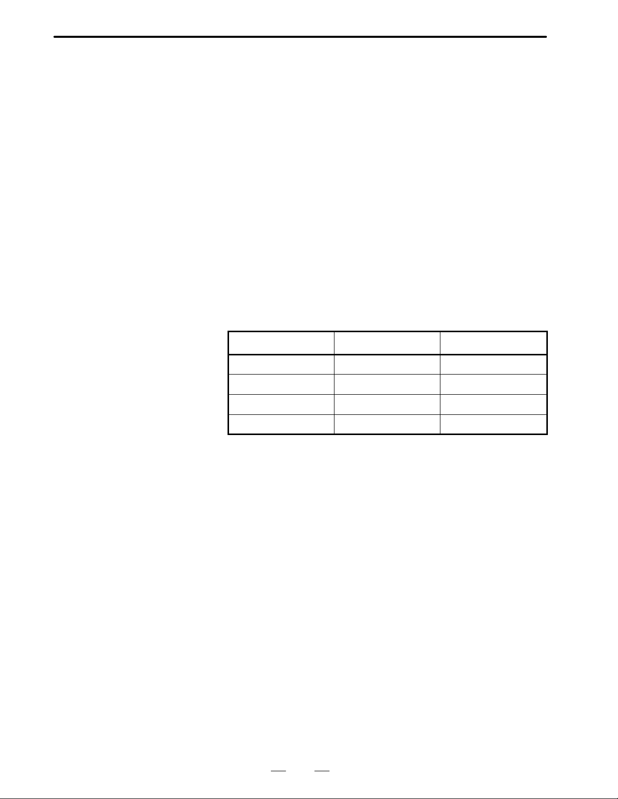
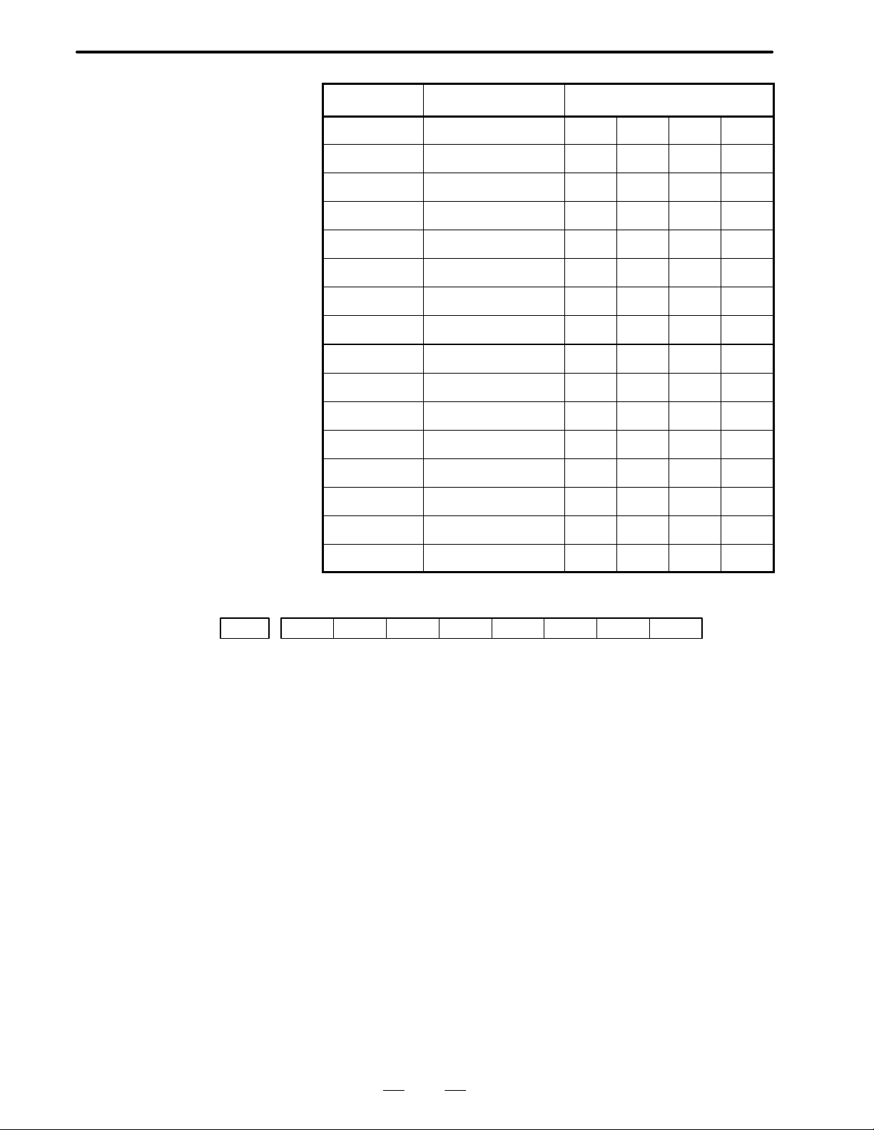
The models covered by this manual, and their abbreviations are:
Product name Abbreviations
FANUC Series 0–TD 0–TD
–
FANUC Series 0–GCD 0–GCD
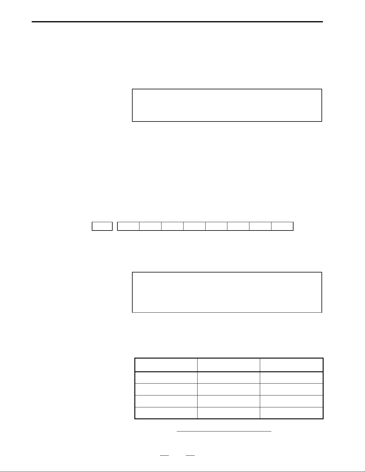
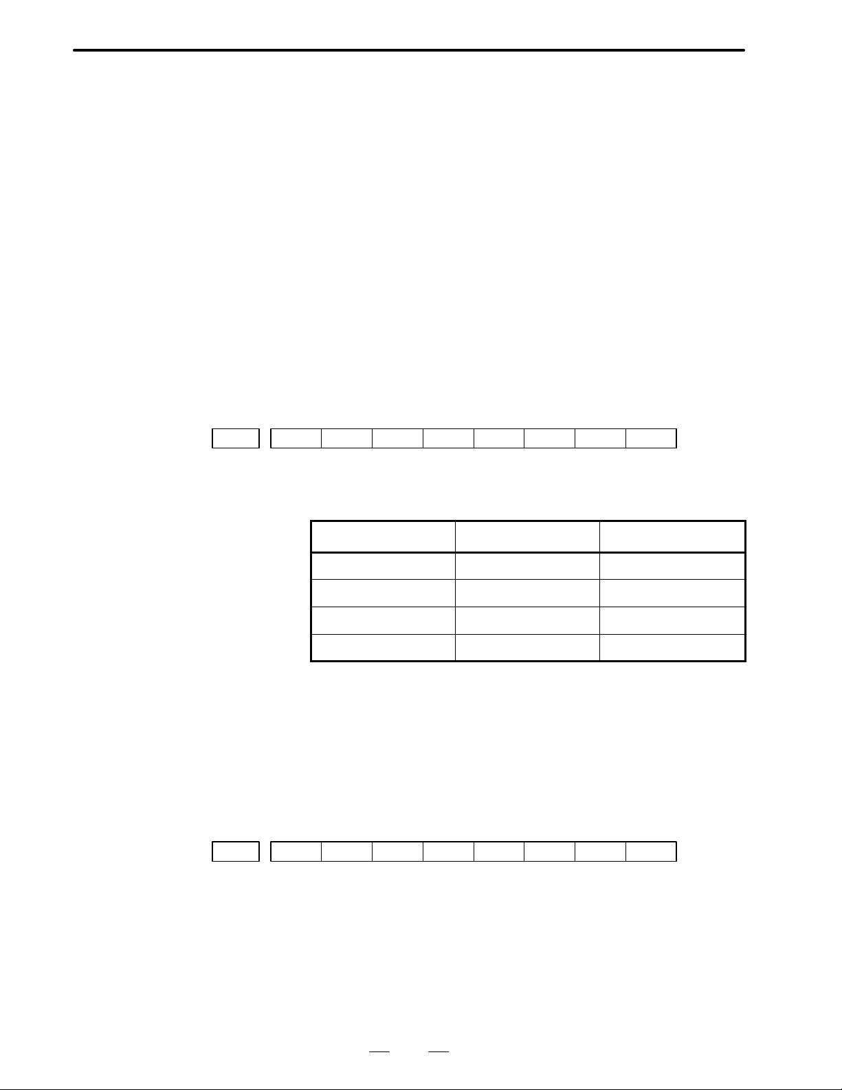
The table below lists manuals related to the FANUC Series 0–D.
In the table, this manual is marked with an asterisk (*).
Table 1 Manuals related to the FANUC Series 0–D
Manuals name
FANUC Series 0–TD/MD/GCD/GSD
CONNECTION MANUAL (HARDWARE)
FANUC Series 0–TD/MD/GCD/GSD
CONNECTION MANUAL (FUNCTION)
FANUC Series 0–TD/GCD OPERATOR’S MANUAL B–62544EN
FANUC Series 0–MD/GSD OPERATOR’S MANUAL B–62574EN
FANUC Series 0–TD/MD/GCD/GSD MAINTENANCE
MANUAL
FANUC Series 0–TD/GCD PARAMETER MANUAL B–62550EN *
FANUC Series 0–MD/GSD PARAMETER MANUAL B–62580EN
Specification
number
B–62543EN
B–62543EN–1
B–62545EN
p–1
Page 3

B–62550EN/01
Table of Contents
PREFACE p–1. . . . . . . . . . . . . . . . . . . . . . . . . . . . . . . . . . . . . . . . . . . . . . . . . . . . . . . . . . . . . . . . . . .
1. LIST OF PARAMETERS FOR EACH FUNCTION 1. . . . . . . . . . . . . . . . . . . . . . . . . . . . . . . .
(1) Parameters related to setting 2. . . . . . . . . . . . . . . . . . . . . . . . . . . . . . . . . . . . . . . . . . . . . . . . . . . . . . . . . . . .
(2) Parameters related to the reader/punch interface 2. . . . . . . . . . . . . . . . . . . . . . . . . . . . . . . . . . . . . . . . . . . . .
(3) Parameters related to controlled axes/increment systems 3. . . . . . . . . . . . . . . . . . . . . . . . . . . . . . . . . . . . . .
(4) Parameters related to coordinate systems 4. . . . . . . . . . . . . . . . . . . . . . . . . . . . . . . . . . . . . . . . . . . . . . . . . .
(5) Parameters related to stroke limits 4. . . . . . . . . . . . . . . . . . . . . . . . . . . . . . . . . . . . . . . . . . . . . . . . . . . . . . . .
(6) Parameters related to the feedrate 5. . . . . . . . . . . . . . . . . . . . . . . . . . . . . . . . . . . . . . . . . . . . . . . . . . . . . . . .
(7) Parameters related to acceleration/deceleration control 6. . . . . . . . . . . . . . . . . . . . . . . . . . . . . . . . . . . . . . .
(8) Parameters related to the servo system 7. . . . . . . . . . . . . . . . . . . . . . . . . . . . . . . . . . . . . . . . . . . . . . . . . . . .
(9) Parameters related to DI/DO 8. . . . . . . . . . . . . . . . . . . . . . . . . . . . . . . . . . . . . . . . . . . . . . . . . . . . . . . . . . . .
(10) Parameters related to CRT/MDI, display, and editing 9. . . . . . . . . . . . . . . . . . . . . . . . . . . . . . . . . . . . . . . . .
(11) Parameters related to programs 11. . . . . . . . . . . . . . . . . . . . . . . . . . . . . . . . . . . . . . . . . . . . . . . . . . . . . . . . .
(12) Parameters related to pitch error compensation 11. . . . . . . . . . . . . . . . . . . . . . . . . . . . . . . . . . . . . . . . . . . . .
(13) Parameters related to spindle control 12. . . . . . . . . . . . . . . . . . . . . . . . . . . . . . . . . . . . . . . . . . . . . . . . . . . . .
(14) Parameters related to tool compensation 13. . . . . . . . . . . . . . . . . . . . . . . . . . . . . . . . . . . . . . . . . . . . . . . . . .
(15) Parameters related to canned cycles 14. . . . . . . . . . . . . . . . . . . . . . . . . . . . . . . . . . . . . . . . . . . . . . . . . . . . .
(16) Parameters related to custom macros 14. . . . . . . . . . . . . . . . . . . . . . . . . . . . . . . . . . . . . . . . . . . . . . . . . . . . .
(17) Parameters related to run time/parts count display 14. . . . . . . . . . . . . . . . . . . . . . . . . . . . . . . . . . . . . . . . . .
(18) Parameters related to manual handle feed 15. . . . . . . . . . . . . . . . . . . . . . . . . . . . . . . . . . . . . . . . . . . . . . . . .
(19) Parameters related to the software operator’s panel 15. . . . . . . . . . . . . . . . . . . . . . . . . . . . . . . . . . . . . . . . .
(20) Parameters related to PMC–based axis control 16. . . . . . . . . . . . . . . . . . . . . . . . . . . . . . . . . . . . . . . . . . . . .
(21) Parameters related to cylindrical grinding machines (0–GCD) 17. . . . . . . . . . . . . . . . . . . . . . . . . . . . . . . . .
(22) Parameters related to the PMC 17. . . . . . . . . . . . . . . . . . . . . . . . . . . . . . . . . . . . . . . . . . . . . . . . . . . . . . . . . .
(23) Parameters related to the Cf–axis 17. . . . . . . . . . . . . . . . . . . . . . . . . . . . . . . . . . . . . . . . . . . . . . . . . . . . . . .
2. PARAMETER DESCRIPTION 18. . . . . . . . . . . . . . . . . . . . . . . . . . . . . . . . . . . . . . . . . . . . . . . .
3. SETTING PARAMETER 20. . . . . . . . . . . . . . . . . . . . . . . . . . . . . . . . . . . . . . . . . . . . . . . . . . . . .
4. DESCRIPTION OF PARAMETERS 22. . . . . . . . . . . . . . . . . . . . . . . . . . . . . . . . . . . . . . . . . . .
c–1
Page 4

B–62550EN/01
1
1. LIST OF PARAMETERS FOR EACH FUNCTION
LIST OF PARAMETERS FOR EACH FUNCTION
The Parameters for each function is the following. For details, see
“Parameter Explanation”.
(1)Parameters related to setting
(2)Parameters related to the reader/punch interface
(3)Parameters related to controlled axes/increment systems
(4)Parameters related to coordinate systems
(5)Parameters related to stroke limits
(6)Parameters related to the feedrate
(7)Parameters related to acceleration/deceleration control
(8)Parameters related to the servo system
(9)Parameters related to DI/DO
(10) Parameters related to CRT/MDI, display, and editing
(11) Parameters related to programs
(12) Parameters related to pitch error compensation
(13) Parameters related to spindle control
(14) Parameters related to tool compensation
(15) Parameters related to canned cycles
(16) Parameters related to custom macros
(17) Parameters related to run time/parts count display
(18) Parameters related to manual handle feed
(19) Parameters related to the software operator’s panel
(20) Parameters related to PMC–based axis control
(21) Parameters related to cylindrical grinding machines (0–GCD)
(22) Parameters related to the PMC
(23) Parameters related to the Cf–axis
NOTE
In the explanation of each bit parameter, the left–hand side
of a slash (/) indicates the state when the bit is set to 0, and
the right–hand side of a slash indicates the state when the
bit is set to 1.
Example : The current setting is 0/1.
1
Page 5

1. LIST OF PARAMETERS FOR EACH FUNCTION
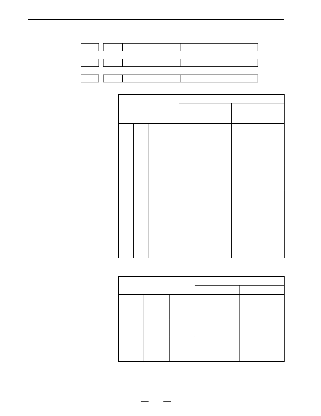
(1) Parameters related to setting (1/1)
No. Symbol Description
0000 TVON A TV check is not performed/is performed for program registration.
0000 ISO EIA/ISO is used as the code system for program output.
0000 INCH The metric/inch system is used as the least input increment (input unit) for programs.
0000 I/O Input/output unit used via the reader/punch interface
0000 SEQ Automatic sequence number insertion is not performed/is performed.
0000 PWE Parameter write operation is disabled/enabled.
(2) Parameters related to the reader/punch interface (1/1)
No. Symbol Description
B–62550EN/01
0002#0
0012#0
0002#2
0012#2
0002#3
0012#3
0002#7
0012#7
0015#5 PRWD The rewind signal is not output/is output to a portable tape reader.
0015#6 REP If the same program number is already contained in memory when programs are regis-
0018#6 TVC In a program comment, a TV check is performed/is not performed.
0038#6, #7
0070#7 ICR In output using ISO code, the EOB code consists of an LF, CR, and CR/LF.
0075#7 IONUL When a null character is included in EIA code being read, an alarm is not issued/is
0391#6 RS23BN When the RS–232–C interface is used, the DC code is used/not used.
,
STP2
STP2
ASR33
ASR33
RSASCI
RSASCI
NFED
NFED
(I/O=0) The number of stop bits is 1/2.
(I/O=1)
(I/O=0) FANUC PPR, etc./20–mA current interface
(I/O=1)
(I/O=0) ISO or EIA/ASCII is used as the input code.
(I/O=1)
(I/O=0) Line feed codes are output/not output before and after data output.
(I/O=1)
tered via the reader/punch interface, an alarm is issued/the program is replaced.
(I/O=0,1) Input/output unit setting
issued.
0399#6 FEDNUL For feed operation in a significant information section, space/null characters are used.
0552
0553
– – – – – –
– – – – – –
(I/O=0) Baud rate
(I/O=1)
2
Page 6

B–62550EN/01
1. LIST OF PARAMETERS FOR EACH FUNCTION
(3) Parameters related to controlled axes/increment systems (1/1)
No. Symbol Description
0001#0 SCW The metric/inch system is used for the least command increment (output unit) for linear
axes.
0003#0 to #2 ZM (X to 3) The reference position return direction and initial direction are positive/nega-
tive.
0019#2 XRC For the X–axis, a diameter/radius is specified.
0024#1 LII10 The input/output unit is IS–B/IS–A.
0030#0
0210
0032#2 LIN3 The third axis is rotation axes/linear axes.
0032#7 ROT10 The parameter unit for inch output is 0.1 [deg/min]/1 [deg/min].
0049#4 S3JOG The maximum number of simultaneously controlled axes in manual operation is 1/3.
0057#3 MIC When the decimal point is omitted, the least input increment is not multiplied by
0069#4 BAX As a command address for the third axis, B is not used/used.
0069#5 Incremental or absolute command address for the third axis
0074#0 to #2 CRF If a command other than G28 specifies a movement by automatic operation when ref-
0076#1 JZRN The function for setting the reference position without dogs is disabled/enabled.
0385#6 RTLIN Manual reference position return operation for a rotation axis is not performed/is per-
0388#1 ROAXC The roll–over function for absolute coordinates is disabled/enabled.
0388#2 RODRC When the ABS command is specified, the direction of rotation is the direction with the
ADW30
– – – – – –
(3) Axis name (Display)
(3) (Command)
10/multiplied by 10.
erence position return is not performed, an alarm is not issued/is issued.
formed linearly .
shortest distance/follows the sign of the specified value.
0388#3 ROCNT The roll–over function for relative coordinates is disabled/enabled.
0388#5 IGPS90 P/S 090 is enabled/disabled.
0391#0 to #2 JZRN The function for setting the reference position without dogs is enabled/disabled.
0399#7 OUTZRN If there is distance remaining to travel in manual reference position return, or a miscel-
laneous function is being executed, an alarm (P/S 091) is issued/not issued.
0269 to 0271 – – – – – – Servo axis number
0279 – – – – – – Attributes of the third axis
3
Page 7

1. LIST OF PARAMETERS FOR EACH FUNCTION
(4) Parameters related to coordinate systems (1/1)
No. Symbol Description
0002#1 PPD Relative coordinates are not preset/are preset by coordinate system setting.
0010#6 WSFT Workpiece coordinate system shift operation is not performed/is performed.
B–62550EN/01
0010#7
7010#7
0028#5 RSFT In direct input of a workpiece coordinate system shift amount, a diameter value/radius
0075#6 CLCL The local coordinate system is not canceled/is canceled in manual reference position
0388#6 WKZRST In workpiece coordinate system setting, the workpiece coordinate system is not re-
0388#7 WKZSFT The workpiece shift and offset from the external workpiece reference point are not
0708 to 0710
0815 to 0817
0735 to 0737 – – – – – – (X to 3) Distance of the second reference position from the first reference position
0788 – – – – – – Travel distance per rotation of a rotation axis
0940 to 0943 – – – – – – Offset from the external workpiece reference point for each axis
0944 to 0947 – – – – – – Offset from the first workpiece reference point for each axis (G54)
0948 to 0951 – – – – – – Offset from the second workpiece reference point for each axis (G55)
0952 to 0955 – – – – – – Offset from the third workpiece reference point for each axis (G56)
APRS
APRSS
– – – – – –
– – – – – –
Automatic coordinate system setting is not performed/is performed in manual reference position return operation.
value is entered for the value of MX.
return.
turned/is returned to G54 by an NC reset.
stored/are stored in the same memory location.
(X to 3) Reference position coordinates in automatic coordinate system setting
(X to 3)
0956 to 0959 – – – – – – Offset from the fourth workpiece reference point for each axis (G57)
0960 to 0963 – – – – – – Offset from the fifth workpiece reference point for each axis (G58)
0964 to 0967 – – – – – – Offset from the sixth workpiece reference point for each axis (G59)
7717 – – – – – – Machine coordinate system when the fifth/sixth axis is a rotation axis
(5) Parameters related to stroke limits (1/2)
No. Symbol Description
0015#2 COTZ The hardware overtravel signals (X018#5 *+LZ, X040#6 *–LZS) are valid/invalid.
0020#4 LM2 The switching signal for the second stored stroke limit is invalid/valid.
0065#3 PSOT A stored stroke limit check is performed/is not performed until reference position return
operation is performed.
0076#7 OTRFOM An alarm is issued after/before a stroke limit is exceeded.
0700 to 0702 – – – – – – (X to 3) First stored stroke limit in the positive direction for each axis
0704 to 0706 – – – – – – (X to 3) First stored stroke limit in the negative direction for each axis
4
Page 8

B–62550EN/01
1. LIST OF PARAMETERS FOR EACH FUNCTION
(5) Parameters related to stroke limits (2/2)
No. DescriptionSymbol
0770 to 0772 – – – – – – Second stored stroke limit in the positive direction for each axis
0774 to 0776 – – – – – – Second stored stroke limit in the negative direction for each axis
(6) Parameters related to the feedrate (1/2)
No. Symbol Description
0001#6 RDRN For a rapid traverse command, dry run is disabled/enabled.
0008#4 MFPR Manual synchronized feed (feed by spindle rotation) is disabled/enabled.
0008#5 ROVE The rapid traverse override signal (G117#7 ROV2) is valid/invalid.
0010#0 ISOT When no reference position is established, manual rapid traverse is disabled/enabled.
0015#3 SKPF When G31 is specified, dry run, override, and automatic acceleration/deceleration are
disabled/enabled.
0041#2 ZRNJF Manual reference position return is not performed/performed at the jog feedrate.
0049#6 NPRV When no position coder is used, the command for feed per rotation is disabled/en-
abled.
0049#7 FML10 The units of the parameters for setting the rapid traverse rate and cutting feedrate are
not multiplied/are multiplied by 10.
0065#5 G92ZAX The parameters for a Z–axis time constant in threading and for an FL feedrate for ac-
celeration/deceleration are common to all axes/Nos. 0627 and 0628.
0077#5 MICRF The unit of the feedrate specified in F is 1 [mm/min]/0.001 [mm/min].
0393#5 STOVO In rapid traverse, the tool is not stopped/stopped when a cutting feedrate override of
0% is specified.
0394#1 TFHOVR The rapid traverse override for threading cycle retraction is the parameter–specified
value/100 [%].
0397#2 OVR255 The 1%–step feedrate override signal is invalid/valid.
0518 to 0520 – – – – – – (X to 3) Rapid traverse rate for each axis
0527 – – – – – – Maximum allowable cutting feedrate
0528 – – – – – – FL feedrate for acceleration/deceleration along the X–axis in threading (G92)
0530 – – – – – – (X to 3) FL feedrate for exponential acceleration/deceleration in cutting feed
0533 – – – – – – (X to 3) F0 feedrate for rapid traverse override
0534 – – – – – – (X to 3) FL feedrate for reference position return
0548 – – – – – – FL feedrate for exponential acceleration/deceleration in manual feed
0559 to 0561 – – – – – – Jog rapid traverse rate for each axis
0605 to 0607 – – – – – – FL feedrate for exponential acceleration/deceleration in manual feed for each axis
5
Page 9

1. LIST OF PARAMETERS FOR EACH FUNCTION
B–62550EN/01
(6) Parameters related to the feedrate (2/2)
No. DescriptionSymbol
0628 – – – – – – FL feedrate for acceleration/deceleration along the Z–axis in threading (G92)
0657 to 0659 – – – – – – (X to 3) FL feedrate for exponential acceleration/deceleration in cutting feed for PMC
axes
(7) Parameters related to acceleration/deceleration control (1/1)
No. Symbol Description
0020#5 NCIPS An in–position check is performed/is not performed.
0050#4 SMZCT Rapid traverse block overlap is invalid/valid.
0065#5 G92ZAX The parameters for a Z–axis time constant in threading and for an FL feedrate for ac-
celeration/deceleration are common to all axes/Nos. 0627 and 0628.
0522 to 0524 – – – – – – (X to 3) Time constant for rapid traverse using linear acceleration/deceleration for
each axis
0526 – – – – – – Time constant for the X–axis in threading (G92)
0529 – – – – – – Time constant for exponential acceleration/deceleration in cutting feed and manual
feed
0555 – – – – – – Feedrate ratio at which the next block is started for rapid traverse block overlap
0601 to 0603 – – – – – – (X to 3) Time constant for exponential acceleration/deceleration in manual feed for
each axis
0627 – – – – – – Time constant for the Z–axis in threading (G92)
0651 to 0653 – – – – – – (X to 3) Time constant for exponential acceleration/deceleration in cutting feed for
PMC axes
6
Page 10

B–62550EN/01
1. LIST OF PARAMETERS FOR EACH FUNCTION
(8) Parameters related to the servo system (1/1)
No. Symbol Description
0004 to 0006
0570 to 0572
0004 to 0006 DMR (X to 3) Detection multiplication factor (DMR) for each axis
0010#2 OFFVY If VRDY=1 is set before PRDY=1, an alarm is issued/is not issued.
0021#0 to #2 APC (X to 3) For each axis, an absolute–position detector is not used/used.
0021#6 NOFLUP When the power is turned on before a reference position is established with an abso-
0022#0 to #2 ABS (X to 3) A reference position is not established/is already established with an abso-
0035#7 ACMR (X to 3) An arbitrary CMR is not used/is used.
0037#0 to #2 SPTP (X to 3) As a position detector, a separate pulse coder is not used/is used.
0037#7 PLC01 (X to 8) A high–resolution pulse coder is not used/is used.
0041#1 THRDB The threading start type is type A/type B.
0076#4 ADBLS Cutting feed and rapid traverse separate backlash compensation is invalid/valid.
0389#3 TSKECR When the torque limit skip function is used, the servo error present at the time of skip-
0390#0 to #3 NREQ When a reference position is not established upon power–up, an alarm is issued/is not
GRD
– – – – – –
(X to 3) Size of a reference counter for each axis
(X to 3)
lute–position detector, follow–up operation is performed/is not performed.
lute–position detector.
ping is recovered/not recovered.
issued to request reference position return when an absolute pulse coder is used for
each axis.
0399#4 FUNO When a servo alarm is detected by the CNC, follow–up operation is performed/is not
performed.
0100 to 0102 – – – – – – (X to 3) Command multiplication factor (CMR) for each axis
0255 – – – – – – Time interval for averaged current value display on the servo adjustment screen
0269 to 0271 – – – – – – Servo axis number
0452 to 0454
0739 to 0741
0500 to 0502 – – – – – – (X to 3) In–position width for each axis
0504 to 0506 – – – – – – (X to 3) Limit of position deviation during movement along each axis
0508 to 0510 – – – – – – (X to 3) Grid shift for each axis
0512 to 0515
0517
0535 to 0537 – – – – – – (X to 3) Backlash compensation for each axis
0593 to 0595 – – – – – – (X to 3) Limit of position deviation in the stop state for each axis
0673 to 0675 – – – – – – (X to 3) Rapid traverse backlash compensation value for each axis
– – – – – –
– – – – – –
– – – – – –
– – – – – –
(X to 3 3RD WORD) Counter value at the APC reference position
(X to 3 LOWER 2 WORD)
(X to 3) Position control loop gain for each axis
(X to 3) Position control loop gain common to all axes
7
Page 11

1. LIST OF PARAMETERS FOR EACH FUNCTION
B–62550EN/01
(9) Parameters related to DI/DO (1/1)
No. Symbol Description
0001#2 DCS The signal from the ST ART button on the MDI panel is routed/not routed via the ma-
chine.
0001#5 DECI (X to 3) The deceleration signal for reference position return starts deceleration when
this bit is set to 0/1.
0003#4 OVRI (X to 3) The override signal and rapid traverse override signal increase speed when
this bit is set to 0/1.
0008#7 EILK The start lock signal is common to all axes/defined for each axis.
0009#0 to #2 TFIN (X to 3) Acceptance time width for the M, S, or T function completion signal (G120#3
FIN)
0009#4 to #7 TMF (X to 3) Time before the M, S, or T function code read signal is sent
0024#7 EDILK The interlock signal for each axis direction is invalid/valid.
0031#5 ADDCF The PMC address for the GR1, GR2, and DRN signals is G0118/G0123.
0038#0 DEC34 The PMC addresses for the *DEC3 signal are GX19#7/G16#7.
0041#3 ROVC The rapid traverse override signals are ROV and ROV2/ROV1D, ROV2D, and
ROV3D.
0045#2 RWDOUT The rewind in–progress signal (F164#6 RWD) is output only while the tape reader is
being rewound/while programs in memory are being rewound.
0045#7 HSIF M, S, T, and B code processing is performed using an ordinary/high–speed interface.
0070#4 DSTBGE When output is started in background editing, the manual data input start signal
(F150#5 DST) is output/is not output.
0394#6 POSILK The start lock signal is invalid/valid for manual feed.
0252 – – – – – – Reset signal extension time
8
Page 12

B–62550EN/01
1. LIST OF PARAMETERS FOR EACH FUNCTION
(10) Parameters related to CRT/MDI, display, and editing (1/2)
No. Symbol Description
0001#1 PROD Tool length compensation data is included/is not included in relative coordinate display.
0002#1
7002#1
0010#1 EBCL When programs stored in memory are displayed, the EOB code is displayed using ;/.
0011#7 MCINP Programs are not stored/are stored in memory with G117#0 MINP.
0014#2 STDP The actual speed of the spindle, S codes, and T codes are not displayed/are dis-
0015#0 CBLNK The cursor blinks/does not blink.
0015#1 NWCH When tool wear compensation values are displayed, the character W is displayed/is
0015#6 REP If the same program number is already contained in memory when programs are regis-
0018#7 EDITB The type of editing using the standard keyboard is edit operation A/B.
0019#6 NEOP When a program is registered, M02, M30, or M99 ends/does not end registration.
0019#7 DBCD When the diagnostic screen is displayed, timer and counter data are displayed in
0023#0 to #6 Display language setting
0028#0 PRCPOS On the program check screen, relative/absolute coordinates are displayed.
PPD
PPDS
Relative coordinates are not preset/are preset by coordinate system setting.
played.
not displayed.
tered via the reader/punch interface, an alarm is issued/the program is replaced.
binary/decimal.
0028#2 DACTF Actual speed is not displayed/is displayed.
0029#0 DSP3 The current position of the third axis is not displayed/is displayed.
0040#0 NAMPR Program names are not displayed/are displayed in the program directory.
0040#4 SORT The program directory is displayed in the order of program registration/in the ascend-
ing order of program numbers.
0045#0 RDL During external control of input/output units, read operation follows the specification of
No. 0015#6 REP/registration is performed after deletion of all programs.
0045#1 RAL In reading via the reader/punch interface, all programs are registered/only the first pro-
gram is registered.
0048#7 SFFDSP Soft keys are displayed and controlled according to the additional option function
specification/regardless of the additional option function specification.
0050#1 NOFMK In sequence number search, a format check is performed/is not performed.
0056#0 NOCND When the background edit function is provided, automatic memory compression is
performed/is not performed.
0060#0 DADRDP Addresses are not displayed/are displayed on the diagnostic screen.
0060#2 LDDSPG Dynamic ladder display is not performed/is performed.
0060#5 OPMNDP Operating monitor display is invalid/valid.
0060#6 EXTSP The display and search operations are disabled/enabled for protected programs.
9
Page 13

1. LIST OF PARAMETERS FOR EACH FUNCTION
(10) Parameters related to CRT/MDI, display, and editing (2/2)
No. DescriptionSymbol
0063#0 MTDSPI Output system/input system for machine coordinate display
0063#1 PRSTIN For automatic coordinate system setting based on inch input, No. 0708 and up/No.
0815 and up are used.
0064#0 SETREL For relative coordinate presetting, the relative coordinates are cleared to 0/preset to
arbitrary values.
0064#1 ALLPRE For relative coordinate presetting, the standard specification is used/axis selection is
performed using numeric keys.
0064#5 NPA When an alarm is issued or an operator message is entered, the screen display
switches/does not switch to the alarm screen or message screen.
0076#2 IOP NC program input and output operations can be stopped by resetting the NC/only by
selecting the [STOP] soft key.
0077#6 HLKEY MDI key processing is/is not high–speed.
0078#0 NOINOW Input of a tool wear compensation value through the MDI keys is not prohibited/is pro-
hibited.
B–62550EN/01
0078#1 NOINOG Input of a tool geometry compensation value through the MDI keys is not prohibited/is
prohibited.
0078#2 NOINMV Input of macro variables through the MDI keys is not prohibited/is prohibited.
0389#0 SRVSET The servo setting screen is displayed/is not displayed.
0393#2 WKNMDI In the automatic operation activation state/automatic operation stop state, input of an
offset from the workpiece reference point through the MDI keys is not prohibited/is pro-
hibited.
0393#7 DGNWEB When PWE=0, PMC parameter input is prohibited/is not prohibited.
0394#7 CAKEY On the parameter, diagnostic, and offset screens, one–character cancellation using
the CAN key is disabled/enabled.
0395#1 TLSCUR On the offset screen, the cursor position is not preserved/is preserved.
0395#4 ADDLA During tool–tip radius compensation, if two blocks specifying no movement are speci-
fied consecutively , the offset vector is assumed to be the vector perpendicular to the
movement performed in the previous block at the end point/the intersection vector.
0397#7 SERNAI The details of alarm 409 are not displayed/are displayed.
0257 to 0263 – – – – – – Tool post name (first to seventh characters) displayed on the screen
0337 to 0346 – – – – – – Title character code
0351 to 0355 – – – – – – NC name character code
0550 – – – – – – Incremental value for automatic sequence number insertion
0797 – – – – – – Password
0798 – – – – – – Key
10
Page 14

B–62550EN/01
1. LIST OF PARAMETERS FOR EACH FUNCTION
(11) Parameters related to programs (1/1)
No. Symbol Description
0010#4 PRG9 The editing of subprograms O9000 to O9999 is not prohibited/is prohibited.
0011#6 G01 Upon power–up, the G00/G01 mode is set.
0015#7 CPRD When the decimal point is omitted, the least input increment/mm, inch, deg, or sec unit
is used.
0016#3 NPRD The decimal point input and display function is used/is not used.
0016#5 SPAG An angle for direct drawing dimension programming is specified by angle/supplemen-
tary angle.
0019#5 M02NR After M02 is executed, control returns/does not return to the start of the program.
0028#4 EXTS External program number search is invalid/valid.
0029#4 ADRC As a chamfering or corner R address, C or R/,C or ,R is used.
0030#7 G91 Upon power–up, the G90/G91 mode is set.
0036#1 GSP The G code system is of type A/type B.
0036#5 GSPC The G code system is of type A/type C.
0040#2 MAPS Address Q for the pass point signal output function cannot be used/can be used.
0040#5 TMCR The T code is for a tool function/for calling O9000.
0045#6 CLER The reset button, external reset signal, and emergency stop operation set the reset
state/clear state.
0065#7 M3B One block can contain only one M code/up to three M codes.
0389#2 PRG8 The editing of subprograms O8000 to O8999 is not prohibited/is prohibited.
0391#7 NOCLR When the clear state is entered, certain G codes are cleared/are not cleared.
0393#3 M3RQNG The specification of a three–digit M code is valid/invalid.
0393#6 RADCHK When circular interpolation is specified, the difference between the radius at the start
point and the radius at the end point is not checked/is checked.
0395#0 DLG99 In the feed per rotation mode, a dwell command is specified by time/spindle speed.
0396#7 EORRE If an EOR is read without reading a program end code, an alarm is issued/the reset
state is set.
01 11, 0112 – – – – – – M code which performs no buffering
0876 – – – – – – Arc redius error limit
(12) Parameters related to pitch error compensation (1/2)
No. Symbol Description
0011#0, #1 PML (X to 3) Pitch error compensation magnification
0756 to 0758 – – – – – – (X to 3) Compensation interval in pitch error compensation for each axis
11
Page 15

1. LIST OF PARAMETERS FOR EACH FUNCTION
(12) Parameters related to pitch error compensation (2/2)
No. DescriptionSymbol
1000 to 3000 – – – – – – Zero position for pitch error compensation for each axis
1001 to 3128 – – – – – – Pitch error compensation for each axis
(13) Parameters related to spindle control (1/2)
No. Symbol Description
0003#6, #7 PSG Gear ratio between the spindle and position coder
0013#5 ORCW In orientation, S analog output is positive/negative.
0013#6, #7 TCW, CWM Sign of S analog output
0024#2 SCTO The spindle speed arrival signal (G120#4 SAR) is not checked/is checked.
0028#7 PNOSMP The number of sampling operations for finding the average spindle speed is 4/1.
0049#0 EVSF When an S code is specified, the S code and SF are not output/are output at all times.
B–62550EN/01
0062#3 SPMRPM The unit of parameter data for spindle speed control is 1/10 [RPM].
0071#0 ISRLPC When a serial interface spindle is used, the position coder signal is received through
an optical fiber/M27 connector.
0071#1 HISSC The sampling time for constant surface speed control remains unchanged from the
conventional value/is the conventional value divided by 4.
0071#4 SRL2SP One/two serial interface spindles is/are connected.
0071#7 FSRSP Serial interface spindles are not used/are used.
0074#7 PLCREV A feedback pulse signal from a position coder represents an absolute value/is signed.
0080#2 MORCM1 For the first spindle motor, the spindle orientation function with the stop position set
externally is not used/is used.
0108 – – – – – – Spindle speed when the spindle rotates at a constant speed
01 10 – – – – – – Delay timer used to check the spindle speed arrival signal (G120#4 SAR)
0516 – – – – – – Data for gain adjustment in constant surface speed control (analog output)
0539 – – – – – – Spindle speed of fset value
0540 to 0543 – – – – – – Speed when the spindle speed command voltage for each gear is 10 [V]
0551 – – – – – – Minimum spindle speed in the constant surface speed control mode (G96)
0556 – – – – – – Maximum spindle speed for the constant surface speed control option
0613 – – – – – – Data for second spindle gain adjustment in constant surface speed control
0614 – – – – – – Spindle speed offset value for the second spindle
0615, 0616 – – – – – – Speed when the second spindle speed command voltage for each gear is 10 [V]
0617 – – – – – – Data for third spindle gain adjustment in constant surface speed control
0618 – – – – – – Spindle speed of fset value for the third spindle
12
Page 16

B–62550EN/01
1. LIST OF PARAMETERS FOR EACH FUNCTION
(13) Parameters related to spindle control (2/2)
No. DescriptionSymbol
0619, 0620 – – – – – – Speed when the third spindle speed command voltage for each gear is 10 [V]
7516 – – – – – – Data for gain adjustment in subspindle S4/S5 digit control
7539 – – – – – – Subspindle speed of fset value
(14) Parameters related to tool compensation (1/1)
No. Symbol Description
0001#3 TOC In the reset state, offset vectors are not canceled/are canceled.
0001#4 ORC For offset values, a diameter value/radius value is specified.
0008#6 NOFC Offset values are loaded/are not loaded into a counter.
0010#5 DOFSI Direct input of tool offset values is not performed/is performed.
0013#1 GOFU2 A tool geometry compensation number is specified using the least significant/most
significant digit of a T code.
0013#2 GMOFS Tool geometry compensation is performed by shifting the coordinate system/by moving
the tool.
0013#3 GOFC Tool geometry compensation is not canceled/is canceled by position number 0.
0014#0 T2D A T code is specified using 4 digits/2 digits.
0014#1 GMCL Tool geometry compensation is not canceled/is canceled when the reset state is en-
tered.
0014#4 OFSB Tool of fsetting is performed in a block containing a T code/performed together with axis
movement.
0014#5 WIGA A limit is not imposed/is imposed on tool offset setting.
0014#6 T2T4 When a T code is specified using 2 digits, the upper 2 digits are assumed to be 00/are
assumed to be the same as the lower 2 digits.
0015#4 MORB In direct input of measurement values, the record button is not used/is used.
0075#3 WNPT A virtual tool tip number for tool–tip radius compensation is specified using a geomet-
ric/wear compensation number.
0557 – – – – – – Maximum ignorable travel distance along the outside of a corner in tool–tip radius
compensation
0728 – – – – – – Maximum tool wear compensation value in incremental input
0729 – – – – – – Maximum tool wear compensation value
13
Page 17

1. LIST OF PARAMETERS FOR EACH FUNCTION
(15) Parameters related to canned cycles (1/1)
No. Symbol Description
0393#1 MCQSCH In a multiple repetitive canned cycle for lathes, a sequence number check with Q spe-
cified is not performed/is performed.
0393#4 CHKMRC In a multiple repetitive canned cycle for lathes, specification of a pocket figure is valid/
invalid.
0109 – – – – – – Cut width in threading cycle G92
0717, 0718 – – – – – – Depth of cut/retract dimension in the multiple repetitive canned cycles (G71, G72)
0719, 0720 – – – – – – Retract dimension for each axis in the multiple repetitive canned cycle (G73)
0721 – – – – – – Number of divisions in the multiple repetitive canned cycle (G73)
0722 – – – – – – Return distance in the multiple repetitive canned cycles (G74, G75)
0723 – – – – – – Number of times finishing is performed in the multiple repetitive canned cycle (G76)
0724 – – – – – – Tool angle in the multiple repetitive canned cycle (G76)
0725 – – – – – – Minimum depth of cut in the multiple repetitive canned cycle (G76)
B–62550EN/01
0726 – – – – – – Finishing allowance in the multiple repetitive canned cycle (G76)
(16) Parameters related to custom macros (1/1)
No. Symbol Description
0040#5 TMCR The T code is for a tool function/ for calling O9000.
0040#6 COMC Upon reset, common variables (#100 to #149) are placed/not placed in the null state.
0240 to 0242 – – – – – – M code for calling subprograms O9001 to O9003
(17) Parameters related to run time/parts count display (1/1)
No. Symbol Description
0040#3 RWCNT With M02 or M30, the total number of machined parts and the number of machined
parts is counted/is not counted.
0219 – – – – – – M code for counting the total number of machined parts and the number of machined
parts
0600 – – – – – – Number of required parts
0779 – – – – – – Total number of machined parts
14
Page 18

B–62550EN/01
1. LIST OF PARAMETERS FOR EACH FUNCTION
(18) Parameters related to manual handle feed (1/1)
No. Symbol Description
0002#6 TJHD In the TEACH IN JOG mode, a manual pulse generator is disabled/enabled.
0013#0 JHD In the JOG mode, a manual pulse generator is disabled/enabled.
0077#4 HDLPM When the handle of a manual pulse generator is turned quickly, the scale indication
and travel distance may not match/the scale indication and travel distance match.
0386#0 to #3 HPNEG For each axis, the direction of manual handle feed is the same/opposite.
0386#4 to #7 HDPIG For each axis, the magnification (x 10000) of manual handle feed is used/is not used.
0121 – – – – – – Manual handle feed magnification (M)
0699 – – – – – – Manual handle feed magnification
(19) Parameters related to the software operator’s panel (1/1)
No. Symbol Description
0017#0 OPG1 On the software operator’s panel, mode selection is not performed/is performed.
0017#1 OPG2 On the software operator’s panel, jog feed axis selection is not performed/is per-
formed.
0017#2 OPG3 On the software operator’s panel, manual pulse generator axis selection and magnifi-
cation switching are not performed/are performed.
0017#3 OPG4 On the software operator’s panel, jog feedrate override switching is not performed/is
performed.
0017#4 OPG5 On the software operator’s panel, BDT, SBK, MLK, and DRN switching is not per-
formed/is performed.
0017#5 OPG6 On the software operator’s panel, protect switching is not performed/is performed.
0017#6 OPG7 On the software operator’s panel, feed hold switching is not performed/is performed.
0130 to 0137 – – – – – – Jog feed axes and directions of the keys on the software operator’s panel
0140 to 0203 – – – – – – Character codes of the general–purpose switches on the software operator’s panel
15
Page 19

1. LIST OF PARAMETERS FOR EACH FUNCTION
(20) Parameters related to PMC–based axis control (1/1)
No. Symbol Description
B–62550EN/01
0032#4
7032#4
0032#6 EACSB PMC axis control is based on specification A/B.
0049#5 EFML10 A feedrate command (cutting feed) for PMC axis control is multiplied by 1/10.
0052#0 to #2 NODIC Current position display for PMC axis control follows the decimal point position based
0061#0 to #5 EBC For each axis, group A/B of the DI and DO signals for PMC axis control (specification
0062#6 AXPCF Movement along a PMC controlled axis is added/is not added to actual speed display.
0063#5
7063#5
0066#3 EPMSKP In PMC–based axis control, the same skip signal used with the CNC/a separate signal
0066#6, #7 ERVF Magnification of a feedrate for feed–per–rotation in PMC axis control
0078#4 OVRIE In PMC axis control, the override signal increases speed when this bit is set to 0/1.
0078#6 RDRNE In PMC axis control, the dry run function cannot/can be used with a rapid traverse
0078#7 EAXOVE In PMC axis control, the dry run and override signals are the same as those used with
PNGMLK
PNGMLKS
EAXOV
EAXOVS
Machine locking along a PMC axis is enabled/disabled.
on the setting unit 1/10/follows the standard specifications.
B) is used.
For PMC axes, the dry run and override functions are disabled/enabled.
is used.
command.
the CNC/separate dry run and override signals are used.
0387#7 EFERPD A rapid traverse rate in PMC axis control is specified by the same parameter as with
the CNC/specified by the feedrate data of an axis control command.
0350 – – – – – – Axis for which a feedrate is specified in PMC axis control
0651 to 0653 – – – – – – (X to 3) Time constant for exponential acceleration/deceleration during cutting feed
for a PMC axis
0657 to 0669 – – – – – – (X to 3) FL feedrate for exponential acceleration/deceleration during cutting feed for a
PMC axis
0672 – – – – – – FL feedrate for reference position return operation along a PMC controlled axis
0685 – – – – – – F0 feedrate for independent rapid traverse override along a PMC controlled axis
0698 – – – – – – Maximum feedrate for feed per rotation along a PMC controlled axis
16
Page 20

B–62550EN/01
1. LIST OF PARAMETERS FOR EACH FUNCTION
(21) Parameters related to cylindrical grinding machines (0–GCD) (1/1)
No. Symbol Description
0033#0 to #3 P1S The skip signal used with G31 P1 is invalid/valid.
0033#4 to #7 P2S The skip signal used with G31 P2 is invalid/valid.
0034#0 to #3 P3S The skip signal used with G31 P3 is invalid/valid.
0034#4 to #7 P4S The skip signal used with G31 P4 is invalid/valid.
0035#0 to #3 DS The skip signal used with the dwell skip function is invalid/valid.
0036#0 AGLST Slanted axis control is not exercised/is exercised.
0036#1 GSP The G code system is type A/type B.
0036#2 ZRTM1 Movement is performed/is not performed along the Z–axis in manual reference posi-
tion return operation along the X–axis.
0036#4 G98 Upon power–up, the feed–per–rotation mode/feed–per–minute mode is set.
(22) Parameters related to the PMC (1/1)
No. Symbol Description
0024#0 IGNPMC PMC–based control is enabled/disabled.
0028#1 PRCMSG The program check screen displays the remaining travel distance/message from the
PMC.
0060#1 PCLDB The baud rate used for ladder loading is 4800 [bps]/9600 [bps].
0070#6 PEXRD The R and D areas of the PMC–M are not expanded/are expanded.
0071#6 DPCRAM When a PMC RAM board is used, PMC LOAD MENU is displayed/is not displayed.
0356 to 0359 – – – – – – Number of characters displayed in the remaining travel distance field on the program
check screen
0476 to 0479 – – – – – – Start PMC address where remaining travel distance field characters are set
(23) Parameters related to the Cf–axis (1/1)
No. Symbol Description
0031#6 ESFC In the turning mode, a feedback pulse signal from a position detector is invalid/valid.
0031#7 CNRST In reference position return operation, a relative coordinate along the Cf–axis is not
cleared/is cleared.
0032#7 ROT10 The parameter unit for inch output is 0.1 [deg/min]/1 [deg/min].
17
Page 21

2. PARAMETER DESCRIPTION
PARAMETER DESCRIPTION
2
B–62550EN/01
[01. Setting method]
1) Preparation
(A) Select the MDI mode.
(B) Press the function button [DGNOS/PARAM] to display the
parameter setting screen.
(C) Key in address “No.” and value “0” in the stated order , then press
the [INPUT] button; the setting parameter screen will appear. Set
PWE = 1.
(D) Executing the above steps enables parameter input.
2) Setting
(A) On the parameter setting screen, key in address “No.” and the
desired parameter number in the stated order, then press the
[INPUT] button. The desired number will be searched for. Using
the cursor/page key can also switch the screen sequentially.
(B–1) Bit–type parameter
Specify 0 or 1 in the 8 bits of the parameter. One parameter
consists of 8 bits. Bit 7 is the highest bit, and bit 0 is the lowest.
It is impossible to set or reset an individual bit separately from
another bit. All bits must be manipulated simultaneously.
Example)
If you want to change “00001000” to “10001000”, key in
“10001000”[INPUT].
The highest bit must be entered first, then the next highest,
and so on. The lowest bit must be entered last. If only less
than 8 bits are entered, any bit left unspecified is regarded
as 0.
Example)
“1001[INPUT]” is equivalent to “0001001[INPUT]”.
(B–2) Nonbit–type parameter
Key in a value within the valid data range, and press the
[INPUT] button.
3) Resume the setting that was changed in item 1).
NOTE
Set all parameters that were not explained to 0.
18
Page 22
B–62550EN/01
2. PARAMETER DESCRIPTION
[02. Terminology]
Least input increment (input unit):
The unit of measure used in programming. The least input increment varies with
the increment system used (1/10 or 10 times). For the linear axis, it also varies
depending on whether a metric or inch input is selected.
Least command increment (output unit):
The unit of measure used by the NC when it gives instructions to the
machine. The least command increment varies depending on whether the
machine is a metric or inch type.
Detection increment:
The unit of measure used in detecting the machine position.
IS–A:
The input/output unit is 0.01 [mm]/0.001 [inch].
IS–B:
The input/output unit is 0.001 [mm]/0.0001 [inch].
IS–C:
The input/output unit is 0.0001 [mm]/0.00001 [inch].
No. 0079#6 F0DIC No. 0024#1 LII10 Input increment
[03. Cautions]
0 0 IS–B
0 1 IS–A
1 0 IS–C
1 1 IS–B
1) If a parameter with “POWER OFF” is rewritten, the P/S 000 alarm
(turn off the power) occurs. In this case, it is necessary to turn off the
power. This also applies when the programmable parameter input
(G10) function is used to rewrite the parameter.
2) Always set undefined parameter numbers/bits to 0.
19
Page 23

3. SETTING PARAMETER
SETTING PARAMETER
3
B–62550EN/01
[SETTING 1]
(1) TVON :Specifies whether to make a TV check when a program is
registered in memory.
1 : Makes a TV check.
0 : Does not make a TV check.
NOTE
1 The TV check (tape vertical parity check) function makes a
parity check for each block. This function issues an alarm
(P/S 002) if one block (from one EOB to the next EOB)
contains an odd number of characters.
2 Parameter No. 0018#6 (TVC) determines whether to make
a TV check on comments in a program.
(2) ISO : Specifies which code system is to be used in outputting a
program from memory.
1: ISO code
0: EIA code
NOTE
1 This parameter is valid under the following condition.
No. 0002#3 (I/O = 0), No.0012#3 (I/O = 1) RSASCI = 0
2 An automatic decision is made on the code to be used in
registering programs in memory according to the first EOB
code.
LF : ISO code is assumed.
CR : EIA code is assumed.
(3) INCH : Specifies the type of least input increment (input unit) for
programs.
1: Inch input
0: Metric input
NOTE
The least command increment (output unit) is specified by
No. 0001#0 (SCW).
20
Page 24

B–62550EN/01
3. SETTING PARAMETER
(4)I/O : Specifies an input/output unit to be used on the reader/punch
interface.
0: Selects a unit on channel 1.
(Miscellaneous setting = No.0002, I/O unit setting = No.0038#6/7,
baud rate = No.0552)
1: Selects a unit on channel 1.
(Miscellaneous setting = No.0012, I/O unit setting = No.0038#6/7,
baud rate = No.0553)
(5)SEQ : Specifies whether to insert sequence numbers automatically.
1: Automatic insertion
0: No automatic insertion
NOTE
No.0550 specifies what increment is to be used in automatic
insertion.
[SETTING 2]
(6)PWE : Specifies whether to enable parameter writing.
1: Enables.
0: Disables.
21
Page 25

4. DESCRIPTION OF P ARAMETERS
DESCRIPTION OF PARAMETERS
4
B–62550EN/01
POWER OFF
0001
PROD 1 : In the display of relative coordinate value, the programmed position is
RDRN 1 : Dry run is effective for rapid traverse.
#7
SCW 1 : Least command increment is input in inch system.
DCS 1 : Pushing the START button on the MDI panel directly actuate the
TOC 1 : Offset is cancelled by reset button.
ORC 1 : Offset value becomes a diameter designation.
DECI 1 : Deceleration signal “1” in reference point return indicates
#6
RDRN#5DECI#4ORC#3TOC
(Machine tool: inch system )
0 : Least command increment is input in metric system.
(Machine tool:metric system)
If you want to change this parameter, turn off power.
displayed.
0 : In the display of relative coordinate value, the actual position
considering the offset is displayed
CNC start without going through the machine side (MDI mode only)
0 : Pushing the START button on the MDI panel issues the signal to the
machine side. The CNC start is actuated when the CNC receives the
start signal from machine side.
0 : Offset it not cancelled by reset button.
0 : Offset value becomes a radius designation.
deceleration.
0 : Decelerating signal “0” in reference point return indicates
deceleration.
0 : Dry run is not effective for rapid traverse.
#2
DCS#1PROD#0SCW
#7
NFED0002
STP2 1 : In the reader/puncher interface, the stop bit is set by 2 bits.
PPD 1 : The relative coordinate value is preset when the coordinate system is
#6
TJHD
0 : In the reader/puncher interface, the stop bit is set by 1 bit.
(Effective when the setting parameter I /O is 0.)
NOTE
The band rate is set by parameter No.0552.
set.
0 : The relative coordinate value is not preset when the coordinate system
is set.
#5 #4 #3
RSASCI#2ARS33#1PPD#0STP2
22
Page 26
B–62550EN/01
4. DESCRIPTION OF P ARAMETERS
ARS33 1 : The 20mA current interface is used as the reader / puncher interface.
0 : FANUC PPR, F ANUC cassette, or portable tape reader are used as the
reader / punch interface. (Effective when the setting parameter I /O is
0.)
RSASCI 1 : ASCII code is used for reader/puncher interface.
0 : ISO/EIA code is used for reader/puncher interface.
NOTE
This parameter is valid only when I/O on (SETTING 1) is set
to “0”.
TJHD 1 : Handle feed in the TEACH IN JOG mode by manual pulse generator
is possible.
0 : Handle feed in the TEACH IN JOG mode by manual pulse generator
is not possible.
NFED 1 : Feed is not output before and after program is output by using the
reader/puncher interface. (Set “1” for FANUC cassette.)
0 : Feed is output before and after program is output by using the reader/
puncher interface.
(Effective when the setting parameter I/O is 0.)
POWER OFF
#7
PSG20003
#6
PSG1
#5 #4
OVRI
#3 #2
ZM3
#1
ZMZ
#0
ZMX
ZMX, ZMZ, ZM3 The reference point return direction and the backlash initial direction at
power on for X, Z, 3rd and 4th axes in order
1: Minus
0: Plus
NOTE
The backlash compensation is initially performed when the
axis moves in the opposite direction against the direction
which is set by this parameter after the power is turned on.
OVRI 1 : When the polarity of override signal (*OV1 to +OV8, ROV1, ROV2)
is set to 1, the speed increases.
0 : When it is set to 0, the speed increases.
PSG2, 1 Gear ratio of spindle and position coder.
Magni–fication PSG2 PSG1
1 0 0
2 0 1
4 1 0
8 1 1
Magnification=
Number of spindle rotation
Number of position coder rotation
23
Page 27
4. DESCRIPTION OF P ARAMETERS
B–62550EN/01
POWER OFF
0004
0005
0006
#7
#7
#7
#6 #5
DMRX
#6 #5
DMRZ
#6 #5
DMR3
#4 #3 #2 #1 #0
GRDX
#4 #3 #2 #1 #0
GRDZ
#4 #3 #2 #1 #0
GRD3
GRDX to GRD3 Capacity of reference counter
Setting code Capacity of reference counter
Except for 0.1µ detec-
tor for
3 210
Digital servo
0 0 0 0 1000 10000
0 0 0 1 2000 20000
0 0 1 0 3000 30000
0 0 1 1 4000 40000
0 1 0 0 5000 50000
0 1 0 1 6000 60000
0 1 1 0 7000 70000
0 1 1 1 8000 80000
1 0 0 0 9000 90000
1 0 0 1 10000 100000
1 0 1 0 11000 110000
1 0 1 1 12000 120000
1 1 0 0 13000 130000
1 1 0 1 14000 140000
1 1 1 0 15000 150000
1 1 1 1 16000 160000
0.1µ detector for Digi-
tal servo
DMRX to DMR3 Setting of detective multiplier
Setting code Detective multiplier
6 54
Analog servo
Digital servo
0 0 0 1/2 1/2
0 0 1 1 1
0 1 0 1 3/2
0 1 1 2 2
1 0 0 3/2 5/2
1 0 1 3 3
1 1 0 2 7/2
1 1 1 4 4
24
Page 28
B–62550EN/01
4. DESCRIPTION OF P ARAMETERS
#7
EILK0008
#6
NOFC#5ROVE#4MFPR
#3 #2 #1 #0POWER OFF
MFPR 1 : Manual synchronous feed is done.
0 : Manual synchronous feed is not done.
ROVE 1 : Rapid traverse override signal ROV2 is not effective. (100%, Fo)
0 : Rapid traverse override signal ROV2 is effective.
(100%, 50%, 25%, Fo)
NOFC 1 : Offset counter input is not used.
0 : Offset counter input is used.
EILK 1 : Interlock for individual axis (ITX, ITZ, IT3) is valid.
0 : Interlock for all axes (STLK) is valid.
#7
0009
#6 #5
TMF
#4 #3 #2 #1 #0
TFIN
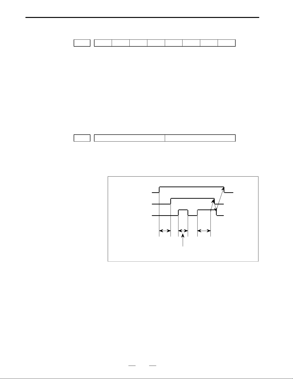
TFIN Time of reception width of FIN.
Setting range : 16 to 256 msec. (16 sec increment).
TMF Time from M, S, T code issue to MF, SF, TF issue.
Setting range : 16 to 256 msec. (16 msec increment).
T cord
TF
FIN
TMF X TFIN
FIN signal is ignored, because X < TFIN
25
Page 29
4. DESCRIPTION OF P ARAMETERS
B–62550EN/01
TMF TFIN Parameter setting
16msec More then 16 msec 0 0 0 0
32msec More then 32 msec 0 0 0 1
48msec More then 48 msec 0 0 1 0
64msec More then 64 msec 0 0 1 1
80msec More then 80 msec 0 1 0 0
96msec More then 96 msec 0 1 0 1
1 12msec More then 112 msec 0 1 1 0
128msec More then 128 msec 0 1 1 1
144msec More then 144 msec 1 0 0 0
160msec More then 160 msec 1 0 0 1
176msec More then 176 msec 1 0 1 0
192msec More then 192 msec 1 0 1 1
208msec More then 208 msec 1 1 0 0
224msec More then 224 msec 1 1 0 1
240msec More then 240 msec 1 1 1 0
256msec More then 256 msec 1 1 1 1
#7
APRS0010
#6
WSFT#5DOFSI#4PRG9
#3 #2
OFFVY#1EBCL#0ISOT
ISOT 1 : Rapid traverse is effective even when reference point return is not
conducted after turning the power on.
0 : Rapid traverse is invalid unless reference point return is conducted
after turning the power on.
EBCL 1 : In the display of the program stored in the memory, the EOB code is
indicated by *(asterrisk).
0 : In the display of the program stored in the memory, the EOB code is
indicated by; (semicolon).
OFFVY 1 : Servo alarm is not actuated when VRDY is on before PRDY is output.
0 : Servo alarm is acturated when VRDY is on before PRDY is output.
PRG9 1 : The subprograms with program number 9000 to 9999 are protected.
The following edit function are disabled.
(1)Deletion of program
When the deletion of all program is specified, the programs with
programs number 9000 to 9999 are not deleted.
(2)Punch of program
These subprograms are not punched out when the punch of all
programs is specified.
(3)Program number search.
26
Page 30
B–62550EN/01
4. DESCRIPTION OF P ARAMETERS
(4)Edit of program after registration
(5)Registration of program
Registration by MDI key and through paper tape.
(6)Collation of program
0 : The subprograms with program number 9000 to 9999 can also be
edited.
DOFSI 1 : The direct measured value input for tool offset is efective.
0 : The direct measured value input for tool offset is effective.
WSFT 1 : The direct measured value input for tool offset is set in the work shift
memory .
0 : The work coordinate system is not shifted.
APRS 1 : Automatic coordinate system setting is conducted when manual
reference point return is perfomed.
0 : Automatic coordinate system setting is not conducted.
#7
MCINP0011
#6
G01
#5 #4 #3 #2 #1
PML2#0PML1
PML1, 2 Pitch error compensation magnification.
The value, with this magnification multiplied to the set compensation
value, is output.
PML2 PML1 Magnification
0 0 1
0 1
1 0 4
1 1 8
G01 1: G01 mode when power is on.
0: G00 mode when power is on.
MCINP 1: Program input is started with the data input external start signal
MINP.
0: Program input is not started with the data input external start signal
MINP.
#7
NFED0012
#6 #5 #4 #3
RSASCI#2ASR33
#1 #0
STP2
STP2 1: In the reader/puncher interface, the stop bit is set by 2 bits.
0: In the reader/puncher interface, the stop bit is set by 1 bit.
(Effective when the setting parameter I/O is 1.)
ASR33 1: The 20mA current interface is used as the reader/puncher interface.
0: F ANUC PRR, F ANUC cassette, or portable tape reader are used as the
reader/puncher interface (Effective when the setting parameter I/O is
1.)
27
Page 31

4. DESCRIPTION OF P ARAMETERS
RSASCI 1 : ASCII code is used for reader/puncher interface.
NFED 1: Feed is not output before and after the program is output by using the
B–62550EN/01
0 : ISO/EIA code is used for reader/puncher interface.
NOTE
This parameter is valid only when I/O on (SETTING 1) is set
to “1”.
reader/puncher interface
(Set to “1” when FANUC cassette is used.)
0: Feed is output before and after the program is output by using the
reader/puncher interface.
(Effective when the setting parameter I/O is 1.)
Remarks Baudrate is set by parameter No.0553.
#7
TCW0013
#6
CWM#5ORCW
#4 #3
GOFC#2GMOFS#1GOFU2#0JHD
JHD 1 : The manual pulse generator is valid in JOG mode.
0 : The manual pulse generator is invalid in JOG mode.
GOFU2 1 : The geometry offset number is designated by two high order digits of
the T code.
0 : The geometry offset number is designated by two low order digits of
the T code.
GMOFS 1 : The tool geometry offset is cancelled with vector processing, i. e. tool
movement
0 : The tool geometry offset is conducted by the shifting of the coordinate
system.
GOFC 1 : The tool geometry offset is also cancelled with the designation of
offset No.0.
0 : The tool geometry offset is not cancelled with the designation of
offset No. 0
ORCW 1 : Minus output in orientation S analog output.
0 : Plus output in orientation S analog output.
TCW, CWM Output code at S analog output.
TCW CWM Output code
0 0 Plus output for both M03 and M04.
0 1 Minus output for both M03 and M04.
1 0 Plus output for M03, minus output for M04.
1 1 Minus output for M03, Plus output for M04
28
Page 32

B–62550EN/01
4. DESCRIPTION OF P ARAMETERS
#7
0014
#6
T2T4#5WIGA#4OFSB
#3 #2
STDP#1GMCL#0T2D
T2D 1: T code is specified in 2 – digit.
0: T code is specified in 4 – digit.
GMCL 1: Cancels the tool geometry offset vector by resetting.
0: Does not cancel the tool geometry offset vector by resetting .
STDP 1: The actual spindle speed and the T code are always displayed .
0: The actual spindle speed and the T code are not always displayed.
OFSB 1: Tool offset is conducted together with axis movement .
0: Tool offset is conducted by the T code block.
(The tool geometry offset by the shifting of the coordinate system is
conducted by the T code block regardless of this parameter.)
WIGA 1: Setting of the tool wear offset amount is limited to incremental
designation, and the setting of the tool geometry offset amount is
limited to absolute designation.
0: The incremental and absolute designations are possible for both tool
wear offset amount and tool geometry offset amount.
T2T4 1: When the T code is designated with a 2 – digit value, it is regarded that
the two high order digits are equal to the two low order digits and the T
code is set to the 4 – digit value.
0: When the T code is designated with a 2 – digit value, the two high
order digits are regarded as 00, and the T code is set to the 4 – digit
value.
Remarks Effective only when parameter TD2=0 at No.014.
#7
CPRD0015
#6
REP#5PRWD#4MORB#3SKPF#2COTZ#1NWCH#0CBLNK
CBLNK 1 : The cursor does not blink.
0 : The cursor blinks.
NWCH 1 : In the display of tool wear/geometry compensation, “W” is not
displayed in the left of each number.
0 : In the display of tool wear/geometry compensation, “W” is displayed
in the left of each number.
COTZ 1 : The over–travel limit signal (*+LZ) is invalid.
0 : The over–travel limit signal (*+LZ) is valid.
SKPF 1 : Dry run, override and automatic acceleration/deceleration is effective
in skip function (G31).
0 : Dry run, override and automatic acceleration/deceleration is
ineffective in skip function (G31).
MORB 1 : The direct measured value input for tool offset and work coordinate
system shift is performed by retracting both 2 axes after cutting and
pushing the RECORD button.
(FANUC PMC–L/M is necessary for this function)
0 : The RECORD button is not provided for direct measured value input.
29
Page 33

4. DESCRIPTION OF P ARAMETERS
PRWD 1 : Rewind signal is output by portable tape reader.
REP 1 : When the program with same program number in the memory is
CPRD 1 : Unit is set to mm, inch or sec. when the decimal point is omitted in the
B–62550EN/01
0 : Rewind signal is not output by portable tape reader.
registered through reader/puncher interface, the alarm does not occur
and the registered program is replaced.
0 : When the program with same program number in the memory is
registered through reader/puncher interface, the alarm occurs.
address for which the decimal point can be used.
0 : The least input increment is set when the decimal point is omitted in
the address for which the decimal point can be used.
#7
MDEC0016
#6 #5
SPAG
#4 #3
NPRD
#2 #1
RSTMB#0RSTMA
RSTMA 1 : A group decode M signal (M11A to M13B) is cleared by reset
(not available)
0 : A group decode M signal is not cleared by reset.
RSTMB 1 : B group decode M signal (M21A, M22A) is cleared by reset.
(not available)
0 : B group decode M signal is not cleared by reset.
NPRD 1 : Input and display with dicimal point is ineffective.
0 : Input and display with decimal point is effective.
SPAG 1 : A supplementary angle is given in the angle specification in direct
drawing dimensions programming.
0 : Normal specifications in the angle specification in direct drawing
dimensions programming.
X
(X, Y)
SPAG= 0
N3
SPAG= 1
N1
N2
Z
MDEC 1 : M code is output in decode signal. (not available)
0 : M code is output in BCD 2 digits.
#7
0017
#6
OPG7#5OPG6#4OPG5#3OPG4#2OPG3#1OPG2#0OPG1
OPG1 1 : JMode select (MD1 to MD4, ZRN) is conducted from the software
operator’s panel.
0 : Mode select is not conducted from the software operator’s panel.
30
Page 34

B–62550EN/01
4. DESCRIPTION OF P ARAMETERS
NOTE
The above parameters are effective only when the optional
software operator’s panel is selected.
OPG2 1 : Jog feed axis select and jog rapid traverse buttons are actuated with the
software operators’s panel.
0 : The above buttons are not actuated with the software operator’s panel.
OPG3 1 : Axis select (HX, HY , HZ) and magnification (x10, x100) switches for
manual pulse generator are actuated with the software operator’s
panel
0 : The above switches are not actuated with the software operator ’s
panel.
OPG4 1 : Jog feed rate, override, and rapid traverse override switches are
actuated with the software operator’s panel.
0 : The above swicthes are not actuated with the software operator ’s
panel
OPG5 1 : Optional block skip, single block, machine lock and dry run switches
are actuated with the software operator’s panel.
0 : The above switches are not actuated with the software operator ’s
panel.
OPG6 1 : Protect key is actuated with the software operator’s panel.
0 : Protect key is not actuated with the software operator’s panel.
OPG7 1 : Feed hold is effected with the software operator’s panel.
0 : Feed hold is not effected with the software operator’s panel.
#7
EDITB0018
#6
TVC
#5 #4 #3 #2 #1 #0
TVC 1 : No TV check at the comment.
0 : TV check at the comment.
EDITB 1 : Editing on standard keyboard shall be editing operation B.
0 : Editing operation shall be as specified in standard specifications.
#7
DBCD0019
#6
NEOP#5M02NR
#4 #3 #2
XRC
#1 #0POWER OFF
XRC 1 : Radius designated for X axis
0 : Diameter designated for X axis
M02NR 1 : Return to the head of program after executing M02.
0 : Do not return to the head of program after executing M02.
NEOP 1 : M02, M30 and M99 command the end of registration into part
program storage editing area.
0 : M02, M30 and M99 do not command the end of registration into part
program storage editing area.
DBCD 1 : In the diagnosis display, the timer counter data is displayed in
decimal.
0 : The diagnosis display is displayed in binary as usual.
31
Page 35

4. DESCRIPTION OF P ARAMETERS
B–62550EN/01
#7
0020
#6 #5
NCIPS#4LM2
#3 #2 #1 #0
LM2 1 : The switching signal (G129.6) of stroke limit 2 is enabled.
0 : The switching signal (G129.6) of stroke limit 2 is disabled.
NCIPS 1 : In deceleration, the control proceeds to the next block after the
specified speed has become zero.
The control does not confirm that the machine position meets a
specified position.(No inposition checking).
0 : The control proceeds to the next block after the specified speed has
become zero and confirms that the machine position has reached the
specified position in deceleration. (Inposition checking).
POWER OFF
0021
#7
#6
NOFLUP
#5 #4 #3 #2
APCX, Z, 3 1 : Absolute pulse coder is used for each axis.
0 : Incremental pulse coder is used for each axis.
NOFLUP When equipping absolute pulse coder,
1 : there is no coordinate running without axes motion at initial
power–up.
0 : there is coordinate running without axes motion at initial power–up.
APC3#1APCZ#0APCX
POWER OFF
0022
#7
#6 #5 #4 #3 #2
ABS3#1ABSZ#0ABSX
ABSX, Z, 3 1 : Reference point position in absolute pulse coder for each axis is
settled.
0: Reference point position in absolute pulse coder is not settled.
(It is automatically set to “1” when manualreference point return is
executed. Do not change the setting without changing the detector.)
Set 0 without fail when primary field installation and adjustment and
when position detector exchanging. And execute manual reference
point return after power off/on.
#7
0023
#6
DSPN
#5 #4
DITA#3DCHI#2DFRN#1DGRM#0DJPN
DJPN CRT screen is displayed in Japanese.
DGRM CRT screen is displayed in German.
DFRN CRT screen is displayed in French.
DCHI CRT screen is displayed in Chinese (Formosan).
DITA CRT screen is displayed in Italian
DSPN CRT screen is displayed in Spanish.
32
Page 36

B–62550EN/01
4. DESCRIPTION OF P ARAMETERS
#7
EDILK0024
#6 #5 #4 #3 #2
SCTO#1LII10
#0
IGNPMC
IGNPMC 1 : Control by PMC is made ineffective. (Same as without PMC.)
0 : Control by PMC is made effective.
LII10 1 : Input/output increment is 0.01mm/0.001inch.
0 : Input/output increment is 0.001mm/0.0001inch or 0.0001mm/
0.00001inch.
SCTO 1 : Spindle speed reach signal is checked.
0 : Spindle speed reach signal is not checked.
EDILK 1 : Interlock signal per axis direction is valid.
0 : Interlock signal per axis direction is invalid.
0028
#7
PNOSMP
#6 #5
RSFT#4EXTS
#3 #2
DACTF
#1
PRCMSG#0PRCPOS
PRCPOS 1 : On the program check screen, the absolute coordinates are displayed.
0 : The relative coordinates are displayed.
PRCMSG 1 : On the program check screen, a message from PMC is displayed. (not
available)
0 : The remaining motion is displayed.
DACTF 1: Actual speed is displayed on the current positon display screen and
program check screen.
0 : Not displayed.
EXTS 1 : External program number search is valid.
0 : External program number search is invalid.
RSFT 1 : MX value is entered with a radius value in work coordinate system
shift.
0 : MX value is entered with a diameter value in work coordinate system
shift. (It is valid only when radius designation XRC=1.)
PNOSMP 1 : In seeking the average spindle speed, the sampling time is made once.
0 : In seeking the average spindle speed, the sampling is made four times.
(Usually, set 0.)
#7
0029
#6 #5 #4
ADRC
#3 #2 #1 #0
DSP3
DSP3 The current position of 3rd axis is displayed in sequence.
1 : The present position is displayed.
0 : The present position is not displayed.
ADRC 1 : Use “I” or “K” , not “C” for the address in chamfering and corner
radius (R). For the addresses used for direct drawing dimension
programming, use“,C” and “,R ” (a comma is put before C and R).
0 : For the address in chamfering, corner R, and direct drawing
dimension programming, use “C” and “R” as per the standard
specification. (3rd axis cannot be used with address “C”.)
33
Page 37

4. DESCRIPTION OF P ARAMETERS
B–62550EN/01
#7
G910030
#6 #5 #4 #3 #2 #1 #0
ADW30
ADW30 The name of 3rd axis is specified in sequence.
1 : The name is C axis.
0 : The name is B.
G91 1 : When the power is turned on, G91 mode is set.
0 : When the power is turned on, G90 mode is set.
#7
CNRST0031
#6
ESFC#5ADDCF
#4 #3 #2 #1 #0
ADDCF 1 : Signals DRN, GR1, GR2 are set to G123 (DGN 123) of PMC address.
0: Signals DRN, GR1, GR2 are set to G118 (DGN 118).
ESFC 1 : Even in the turning mode (Signal COFF is closed) in Cf axis control,
the feedback pulse from the position detector becomes effective.
0 : The feedback pulse in the turning mode in Cf axis control becomes
invalid.
CNRST 1 : At the time of reference point return, Cf axis relative coordinate value
is cleared.
0 : At the time of reference point return, Cf axis relative coordinate value
is not cleared.
#7
ROT100032
#6
EACSB
#5 #4
PNGMLK
#3 #2
LIN3
#1 #0
LIN3 Selection of linear/rotary axis for 3rd axis.
1 : Linear axis
0 : Rotary axis
PNGMLK 1 : In PMC axis control, machine lock shall be invalid.
0 : In PMC axis control, machine lock shall be valid.
EACSB 1 : PMC axis control is of the B specification.
0 : PMC axis control is of the A specification.
ROT10 1 : The parameter unit of JOG feed, cutting feed upper limit speed, rapid
Fo speed and FL speed for reference point return at the time of inch
output for Cs axis is 1 deg/min
0 : The parameter unit is 0.1 deg/min.
#7
P2S40033
#6
P2S3#5P2S2#4P2S1#3P1S4#2P1S3#1P1S2#0P1S1
P1S1 Specifies whether to enable the skip signal (X0008#7, SKIP) for G31 P1
in the multiple skip function.
1 : Enable
0 : Disable
P1S2 Specifies whether to enable the skip signal (X0008#2, SKIP2) for G31 P1
in the multiple skip function.
1 : Enable
0 : Disable
34
Page 38

B–62550EN/01
4. DESCRIPTION OF P ARAMETERS
P1S3 Specifies whether to enable the skip signal (X0008#3, SKIP3) for G31 P1
in the multiple skip function.
1 : Enable
0 : Disable
P1S4 Specifies whether to enable the skip signal (X0008#4, SKIP4) for G31 P1
in the multiple skip function.
1 : Enable
0 : Disable
P2S1 Specifies whether to enable the skip signal (X0008#7, SKIP) for G31 P2
in the multiple skip function.
1 : Enable
0 : Disable
P2S2 Specifies whether to enable the skip signal (X0008#2, SKIP2) for G31 P2
in the multiple skip function.
1 : Enable
0 : Disable
P2S3 Specifies whether to enable the skip signal (X0008#3, SKIP3) for G31 P2
in the multiple skip function.
1 : Enable
0 : Disable
P2S4 Specifies whether to enable the skip signal (X0008#4, SKIP4) for G31 P2
in the multiple skip function.
1 : Enable
0 : Disable
#7
P4S40034
#6
P4S3#5P4S2#4P4S1#3P3S4#2P3S3#1P3S2#0P3S1
P3S1 Specifies whether to enable the skip signal (X0008#7, SKIP) for G31 P3
in the multiple skip function.
1 : Enable
0 : Disable
P3S2 Specifies whether to enable the skip signal (X0008#2, SKIP2) for G31 P3
in the multiple skip function.
1 : Enable
0 : Disable
P3S3 Specifies whether to enable the skip signal (X0008#3, SKIP3) for G31 P3
in the multiple skip function.
1 : Enable
0 : Disable
P3S4 Specifies whether to enable the skip signal (X0008#4, SKIP4) for G31 P3
in the multiple skip function.
1 : Enable
0 : Disable
P4S1 Specifies whether to enable the skip signal (X0008#7, SKIP) for G31 P4
in the multiple skip function.
1 : Enable
0 : Disable
35
Page 39

4. DESCRIPTION OF P ARAMETERS
P4S2 Specifies whether to enable the skip signal (X0008#2, SKIP2) for G31 P4
P4S3 Specifies whether to enable the skip signal (X0008#3, SKIP3) for G31 P4
P4S4 Specifies whether to enable the skip signal (X0008#4, SKIP4) for G31 P4
B–62550EN/01
in the multiple skip function.
1 : Enable
0 : Disable
in the multiple skip function.
1 : Enable
0 : Disable
in the multiple skip function.
1 : Enable
0 : Disable
#7
ACMR0035
#6 #5 #4 #3
DS4
#2
DS3
#1
DS2
#0
DS1
DS1 Specifies whether to enable the skip signal (X0008#7, SKIP) of the dwell
skip function for the 0–GCD.
1 : Enable
0 : Disable
DS2 Specifies whether to enable the skip signal (X0008#2, SKIP2) of the
dwell skip function for the 0–GCD.
1 : Enable
0 : Disable
DS3 Specifies whether to enable the skip signal (X0008#3, SKIP3) of the
dwell skip function for the 0–GCD.
1 : Enable
0 : Disable
DS4 Specifies whether to enable the skip signal (X0008#4, SKIP4) of the
dwell skip function for the 0–GCD.
1 : Enable
0 : Disable
ACMR 1 : Optional CMR is used.
0 : Optional CMR is not used.
POWER OFF
0036
AGLST Specifies whether to perform angular axis control in the 0–GCD.
#7
#6 #5
GSPC#4G98
1 : Perform
0 : Do not perform
NOTE
Bits 0 (AGLST), 2 (ZRTM1), and 4 (G98) of parameter No.
0036 are parameters dedicated to the 0–GCD.
GSP Specifies the G code system.
1 : Type B
0 : Type A
36
#3 #2
ZRTM1#1GSP#0AGLST
Page 40

B–62550EN/01
4. DESCRIPTION OF P ARAMETERS
ZRTM1 Specifies whether to move the Z–axis during manual reference position
return along the X–axis under angular axis control for the 0–GCD.
1 : Do not move the Z–axis.
0 : Move the Z–axis.
NOTE
Bits 0 (AGLST), 2 (ZRTM1), and 4 (G98) of parameter No.
0036 are parameters dedicated to the 0–GCD.
G98 Specifies the feed mode to be selected when the power to the 0–GCD is
switched on.
1 : Feed per minute
0 : Feed per revolution
NOTE
Bits 0 (AGLST), 2 (ZRTM1), and 4 (G98) of parameter No.
0036 are parameters dedicated to the 0–GCD.
GSPC 1 : Special G code system shall be C type.
0 : Special G code system shall be A type.
POWER OFF
#7
PLC010037
#6 #5 #4 #3 #2
SPTP3#1SPTPZ#0SPTPX
SPTPX to SPTP3 Types of position detector of the X, Z and to the 3rd axis in this order.
1 : The separate type pulse coder is to be used as a detector.
0 : The separate type pulse coder is not to be used as a detector.
PLC01 1 : A pulse coder of 0.1µ detection is to be used.
0 : A pulse coder of 0.1µ detection is not to be used.
NOTE
In case of the 0–GCD with 0.1µ pulse coder, set the
parameters No.504 to 506 and No.508 to 510 in units of 1µ.
(The set data is multiplied by ten within the CNC)
POWER OFF
0038
#7
RSCMD1
#6
DEVFL1
#5 #4 #3 #2 #1 #0
DEC34
DEC34 Changes deceleration signals for reference point return *DEC3 addresses
DEC3=0 DEC3=1
*DEC3 X19.7 X16.7
37
Page 41

4. DESCRIPTION OF P ARAMETERS
RSCMD1, DEVFL1 Setting I/O device of reader/puncher interface channel 1.
B–62550EN/01
RSCMD* DEVFL* I/O device used
0 0 Bubble cassette
0 1 Floppy cassette
1 0 RS232, PPR
1 1 New interface
#7
0040
#6 #5
TMCR#4SORT#3RWCNT#2MPAS
#1 #0
NAMPR
NAMPR 1 : Displays the program name on the directory display screen.
0 : Does not display the program name on the program directory display
screen.
MP AS 1 : Signal output when passing the specified distance is used.
0 : Signal output when passing the specified distance is not used.
RWCNT 1 : Does not count the total number of parts machinedand the number of
parts machined even when M02/M30 are executed.
0 : Counts the total number of parts machined and the number of parts
machined each time M02/M30 are executed.
SORT 1 : At the display of program library, it is displayed in numerical order.
0 : Program library is displayed in normal specification.
TMCR 1 : T code calling subprogram O9000
0 : T code as a normal tool function
#7
0041
#6 #5 #4 #3
ROVC#2ZPNJF#1THRDB
#0
THRDB Type of thread cutting start
1 : B type
0 : A type
ZPNJF 1 : Manual reference point return is executed in the jog feed mode.
0 : Manual reference point return is not executed in the jog feed mode.
Valid only when PMC is provided.
ROVC 1 : Signals ROV1D – ROV3D are used for a rapid traverse override
signal.
0 : Signals ROV1 and ROV2 are used for a rapid traverse override signal.
#7
HSIF0045
#6
CLER
#5 #4 #3 #2
RWDOUT
#1
RAL
#0
RDL
RDL 1 : Registers a program after all programs are erased for reading for I/O
device external control.
0 : The reading is the same as in normal specification for I/O device
external control.
38
Page 42

B–62550EN/01
4. DESCRIPTION OF P ARAMETERS
RAL 1 : Registers only one program for reading through reader/puncher
interface.
0 : Registers all programs for reading through reader/puncher interface.
RWDOUT 1 : No signal is outputted in rewinding.
0 : A signal is outputted in rewinding.
CLER 1 : Selects clear conditions, using the reset button,external reset signal
and emergency stop.
0 : Selects reset conditions, using the reset button, external signal and
emergency stop.
HSIF 1 : M/S/T/B code processing shall be a high–speed interface.
0 : M/S/T/B code processing shall be a normal interface.
0048
#7
SFFDSP
#6 #5 #4 #3 #2 #1 #0
SFFDSP 1 : Soft–key is displayed regardless of equipping options.
0 : Whether soft–key is displayed or not depends on equipping options.
#7
FML100049
#6
NPRV#5EFML10#4S3JOG
#3 #2 #1 #0
EVSF
EVSF 1 : SF signal is output when commanding 4–digit S–code.
0 : SF signal is not output when commanding 4–digit S–code.
S3JOG 1 : The number of simultaneously controlled axes in manual operation is
3 maximum.
0 : The number of simultaneously controlled axes in manual operation is
1 maximum.
EFML10 1 : The feedrate command (cutting feed) of PMC axis control is used by
10 times.
0 : Standard specification.
NPRV 1 : Even when no position coder is provided, the per–revolution feed
command shall be valid. (The per–revolution feed command is
converted automatically to the per–minute feed in CNC.)
0 : When no position coder is provided, the per–revolution feed
command shall be invalid.
FML10 1 : The rapid traverse rate and cutting feed upper limit speed parameter
increment system shall be 10 mm/min or 1 inch/min.
e.g) For 100 m/min, the setting value shall be 10000.
0 : As per normal specifications.
#7
0050
#6 #5 #4
SMZCT
#3 #2 #1
NOFMK
#0
NOFMK 1 : Tape format check is not done during sequence No. search.
0 : Tape format check is done during sequence No. search.
SMZCT 1 : Rapid traverse overlap is valid.
0 : Rapid traverse overlap is invalid.
39
Page 43

4. DESCRIPTION OF P ARAMETERS
B–62550EN/01
#7
0052
#6 #5 #4 #3 #2
NODIC3
#1 #0
NODIC3 1 : The current position display of PMC axis control shall be the same as
in standard specifications, not in accordance with the decimal point
position of increment system 1/10.
0 : The current position display of PMC axis control is in accordance
with the decimal point position of increment system 1/10.
#7
0056
#6 #5 #4 #3 #2 #1 #0
NCOND
NCOND When back–ground edit,
1 : condensing part program memory is not done automatically.
(Condensing is done by pressing soft–key “CONDNS”.)
0 : condensing part program memory is done automatically by CNC
reset after edit operation.
#7
0057
#6 #5 #4 #3
MIC
#2 #1 #0
MIC 1 : At omission of decimal point, the minimum set unit is multiplied by
ten.
0 : At omission of decimal point, the minimum set unit is notmultiplied
by ten.
POWER OFF
0060
#7 #6
EXTSP
#5
OPMNDP
#4 #3 #2
LDDSPG
#1
PCLDB
DADRDP 1 : Addresses X, Y, G, F, R and D are displayed on DGN screen.
0 : Addresses X, Y, G, F, R and D are not displayed on DGN screen.
PCLDB 1 : Baud rate for ladder program loading is 9600.
0 : Baud rate for ladder program loading is 4800.
LDDSPG 1 : Ladder dynamic display is valid.
0 : Ladder dynamic display is invalid.
OPMNDP 1 : Operating monitor display is valid.
0 : Operating monitor display is invalid.
EXTSP 1 : Program No. search and display are valid for the protected part
programs by parameter PRG9.
0 : Program No. search and display are inhibited for the protected part
programs by parameter PRG9.
#7
0061
#6 #5 #4 #3 #2
EBC3#1EBCZ#0EBCX
EBCX – EBC3 1 : B is used for DI/DO of PMC axis control.
0 : A is used for DI/DO of PMC axis control.
#0
DADRDP
40
Page 44

B–62550EN/01
4. DESCRIPTION OF P ARAMETERS
#7
0062
#6
AXPCF
#5 #4 #3
SPMRPM
#2 #1 #0POWER OFF
SPMRPM 1 : Unit of parameters related to the spindle rotation speed is 10 rpm.
0 : Unit of parameters related to the spindle rotation speed is 1 rpm.
AXPCF 1 : Axes movements by PMC axis control are not added in actual speed
display.
0 : Axes movements by PMC axis control are added in actual speed
display.
#7
0063
#6 #5
EAXOV
#4 #3 #2 #1
PRSTIN#0MTDSPI
MTDSPI 1 : Machine coordinate system is displayed to meet the input system.
0 : Machine coordinate system is not displayed to meet the input system.
PRSTIN 1 : When the input is of the inch system, automatic coordinate system
setting is handled as a separate parameter.
0 : When the input is of the inch system, automatic coordinate system
setting is not handled as a separate parameter.
EAXOV 1 : Dry run and override is valid for the PMC axis.
0 : Dry run and override is invalid for the PMC axis.
#7
0064
#6 #5
NPA
#4 #3 #2 #1
ALLPRE#0SETREL
SETREL 1 : Preset is made for each axis in the relative position display.
0 : Preset is as usual.
ALLPRE 1 : Origin setting of relative coordinates is performed by numeric key.
0 : Origin setting of relative coordinates is performed by address key.
NPA 1 : The screen is not switched to the alarm/message screen at occurrence
of alarm or at the entry of operator message.
0 : The screen is switched to the alarm/message screen at occurrence of
alarm or at the entry of operator message.
#7
M3B0065
#6 #5
G92ZAX
#4 #3
PSOT
#2 #1 #0
PSOT 1 : Stored stroke check is ignored until reference point return is finished
after CNC power–up.
0 : Stored stroke check is valid just after CNC power–up.
G92ZAX 1 : Time constant and FL speed of Z–axis during threading are specified
in parameter 627 and 628.
0 : Time constant and FL speed of Z–axis during threading are same as
those during normal cutting.
M3B 1 : Maximum 3M codes can be disignated in one block.
2 : M–code designations in one block are as usual.
41
Page 45

4. DESCRIPTION OF P ARAMETERS
1
BABS
B3AX
B–62550EN/01
#7
ERVF20066
#6
ERVF1
#5 #4 #3
EPMSKP
#2 #1 #0POWER OFF
EPMSKP 1 : Skip signal for PMC axis control is independent of CNC skip signal.
0 : Skip signal for PMC axis control is same as CNC skip signal.
ERVF1, ERVF2
ERVF1 ERVF2 Multiplier for feed per rev. by PMC axis control
0 0
1 1
0 1 10
1 0 100
#7
0069
#6
B3AX#5BABS#4BAX
#3 #2 #1 #0POWER OFF
BAX 1 : B as command address of 3rd axis is used.
0 : B as command address of 3rd axis is not used.
NOTE
This parameters must be set to “0” when using 2nd axiliary
function. Set 0 to BAX.
BABS, B3AX Command addresses of 3rd and axis is specified as follows.
3rd axis
ABS INC
0 0 C H
1 0 C H
0 1 C B
1 1 B H
INC : Incremental command
ABS : Absolute command
NOTE
1 These parameters must be set to “0” when using G–code
system B or C.
2 These parameter decide the command addresses of 3rd
axis. Displayed addresses is specified in parameter 030#0,
ADW30.
#7
ICR0070
#6
PEXRD
#5 #4
DSTBGE
#3 #2 #1 #0
DSTBGE 1 : “DST” is not output when pressing ST AR T key in background edit in
order to punch out part programs.
0 : “DST” is output always when pressing START key.
42
Page 46

B–62550EN/01
4. DESCRIPTION OF P ARAMETERS
PEXRD 1 : Expanded R/D data on PMC–M is used.
0 : Expanded R/D data on PMC–M is not used.
ICR 1 : EOB is punched out as “LF” when punching with ISO code.
0 : EOB is punched out as “LF” “CR” “CR” when punching with ISO
code.
POWER OFF
#7
FSRSP0071
#6
DPCRAM
#5 #4
SRL2SP
#3 #2 #1
HISSC#0ISRLPC
ISRLPC 1 : Position coder cable is connected to M27 on memory PCB when
using serial interface spindle.
0 : Position coder cable is connected to spindle amplifier when using
serial interface spindle.
HISSC 1 : Calculation interval of constant surface speed control is one fourth of
usual interval.
0 : Calculation interval of constant surface speed control is as usual.
SRL2SP 1 : Two serial interface spindles are connected serially.
0 : One serial interface spindle is connected.
DPCRAM 1 : PMC starts automatically at power–up when using PMC RAM board.
0 : “PMC LOAD MENU” is displayed at power–up when using PMC
RAM board.
FSRSP 1 : Serial interface spindles are used.
0 : Serial interface spindles are not used.
0074
#7
PLCREV
#6 #5 #4 #3 #2
CRF3#1CRFZ#0CRFX
CRFX When the motion other than G28 is commanded for X–axis whose
machine coordinate is not fixed yet,
1 : alarm 224 appears.
0 : no alarm appears.
CRFZ When the motion other than G28 is commanded for Z–axis whose
machine coordinate is not fixed yet,
1 : alarm 224 appears.
0 : no alarm appears.
CRF3 When the motion other than G28 is commanded for 3rd–axis whose
machine coordinat is not fixed yet,
1 : alarm 224 appears.
0 : no alarm appears.
PLCREV 1 : Feedback pulse from position coder is considered as data with sign.
0 : Feedback pulse from position coder is considered as data without
sign.
43
Page 47

4. DESCRIPTION OF P ARAMETERS
B–62550EN/01
#7
IONUL0075
#6
CLCL
#5 #4 #3
WNPT
#2 #1 #0
WNPT 1 : Direction of imaginary tool nose is specified by wear offset number.
0 : Direction of imaginary tool nose is specified by geometry offset
number.
CLCL 1 : Local coordinate (G52) is canceled after manual reference point
return is performed.
0 : Local coordinate (G52) is not canceled after manual reference point
return is performed.
IONUL 1 : Alarm appears when detecting a null code in reading EIA code.
0 : No alarm appears when detecting a null code in reading EIA code.
0076
#7
OTRFOM
#6 #5 #4
ADBLS
#3 #2
IOP#1JZRN
#0
JZRN 1 : Dogless reference point return is effective. (*1)
0 : Dogless reference point return is ineffective.
NOTE
This parameter is applied to all axes. To set each axis
individually, set this parameter to 1, then set bits 0 to 2 of
parameter No.0391 as required.
IOP 1 : Soft–key “STOP” interrupts reading/punching.
(Reset operation does not stop reading/punching.)
0 : Reset operation stops reading/punching.
ADBLS 1 : Cutting feed and rapid traverse separate backlash compensation is
valid.
0 : Cutting feed and rapid traverse separate backlash compensation is
invalid.
NOTE
The backlash compensation values for rapid traverse are
specified with parameters No.0673 to 0675.
OTRFOM 1 : Stored stroke limit alarm appears just before exceeding it.
0 : Stored stroke limit alarm appears just after exceeding it.
NOTE
This parameter is valid for stored stroke limit–1 and –2.
44
Page 48

B–62550EN/01
4. DESCRIPTION OF P ARAMETERS
#7
0077
#6
HLKEY#5MICRF#4HDLPM
#3 #2 #1 #0POWER OFF
HDLPM When manual pulse generator is rotated rapidly,
1 : movements always coincide with rotated amounts.
0 : movements happens not to coincide with rotated amounts by
clamping with rapid traverse rate.
MICRF 1 : Command unit of feedrate is 0. 001mm/min.
0 : Command unit of feedrate is 1mm/ min.
HLKEY 1 : MDI key operation is treated as high priority.
0 : MDI key operation is treated as low priority.
0078
#7
EAXOVE
#6
RDRNE
#5 #4
OVRIE
#3
NOINWS#2NOINMV#1NOINOG#0NOINOW
NOINOW 1 : Changing wear offset values by using MDI key is prohibited.
0 : Changing wear offset values by using MDI key is allowed.
NOINOG 1 : Changing geometry offset values by using MDI key is prohibited.
0 : Changing geometry offset values by using MDI key is allowed.
NOINMV 1 : Changing macro variables by using MDI key is prohibited.
0 : Changing macro variables by using MDI key is allowed.
NOINWS 1 : Changing work zero offset values by using MDI key is prohibited.
0 : Changing work zero offset values by using MDI key is allowed.
OVRIE 1 : The logic of override signals for PMC axis control is that “1” means
high speed.
0 : The logic of override signals for PMC axis control is that “1” means
low speed.
NOTE
This parameter is effective only when parameter 078#7
(EAXOVE) is set to “1”.
RDRNE 1 : Dry–run signals are effective for rapid traverse of PMC axis control.
0 : Dry–run signals are ineffective for rapid traverse of PMC axis control.
NOTE
This parameter is effective only when parameter 078#7
(EAXOVE) is set to “1”.
EAXOVE 1 : Dry–run and over– ride signals of PMC axis control are different from
CNC axis control.
0 : Dry–run and over– ride signals of PMC axis control are same as CNC
axis control.
45
Page 49

4. DESCRIPTION OF P ARAMETERS
B–62550EN/01
#7
MTCHK0079
#6
FODIC
#5 #4
KEYPR#3KEYWZ#2KEYMV#1KEYOG#0KEYOW
KEYOW Specifies whether to inhibit changes to the tool wear offset amount from
the MDI when KEY (G122#3) = 0.
1 : Inhibit
0 : Do not inhibit
KEYOG Specifies whether to inhibit changes to the tool geometry offset amount
from the MDI when KEY (G122#3) = 0.
1 : Inhibit
0 : Do not inhibit
KEYMV Specifies whether to inhibit changes to the macro variable from the MDI
when KEY (G122#3) = 0.
1 : Inhibit
0 : Do not inhibit
KEYWZ Specifies whether to inhibit changes to the workpiece reference position
offset amount from the MDI when KEY (G122#3) = 0.
1 : Inhibit
0 : Do not inhibit
KEYPR Specifies whether to inhibit changes to the parameter from the MDI when
KEY (G122#3) = 0.
1 : Inhibit
0 : Do not inhibit
NOTE
Be particularly careful when using this setting, because
changing of the parameters may be disabled unless KEY
(G122#3) = 1.
FODIC Specifies the units of the input/output data, as follows
1 : 0.0001 (mm), 0.0001 (degrees), or 0.00001 (inches). (IS–C)
0 : 0.001 (mm), 0.001 (degrees), or 0.0001 (inches). (IS–B)
MTCHK Specifies whether to check for deviation in the machine position when the
power is switched off.
1 : Check
0 : Do not check
NOTE
This check is performed when the power is switched on. If
a positional deviation is detected, an overtravel alarm 5*6
occurs (where * = axis number). The limits on the deviation
are specified using parameter No.0988 to 0990.
46
Page 50

B–62550EN/01
4. DESCRIPTION OF P ARAMETERS
#7
0080
MORCM1 1 : Spindle orientation whose position is specified from PMC is used for
0 : Spindle orientation whose position is specified from PMC is not used
POWER OFF
0100 CMRX
0101 CMRZ
0102 CMR3
CMRX, CMRZ, CMR3
Command multiply for X, Z, 3rd and 4th axes, respectively.
#6 #5 #4 #3 #2
MORCM1
1st serial interface spindle.
for 1st serial interface spindle.
Setting code Multiplier
1 0.5
2 1
4 2
#1 #0POWER OFF
10 5
20 10
When an arbitrary command multiply (No. 0035 ACMR=1) is used, there
are 2 types of setting methods as follows.
1) When a command multiply is 1/2 to 1/27:
1
Preset value =
+100
Command multiply
2) When a command multiply is 2 to 48 :
Preset value = 2 (Command multiply)
NOTE
1 For (2) above, be sure to set a value such that the command
multiply should be always an integer.
2 Set the backlash compensation and pitch error
compensation values with detection unit when an arbitrary
command multiply is used.
47
Page 51

4. DESCRIPTION OF P ARAMETERS
0108 SPLOW
SPLOW Spindle speed during constant speed spindle rotation, or spindle speed at
[Setting range] 0 to 255
0109 THDCH
THDCH Width of chamfering for thread cutting cycle in G92.
[Setting range] 0 to 127 (unit: 0.1 lead)
0110 SCTTIM
SCTTIM Set the delay timer for checking the spindle speed reach signal. This sets
[Setting range] 0 to 255 (unit: msec)
B–62550EN/01
gear shift. (when parameter No. 0003, GST=1),
Spindle motor speed at gear shift
Setting value =
4095
Max. motor speed
(unit : rpm (10 [rpm] by parameter (No.0062 #3)=1))
the time required from execution of the S function to the beginning of
checking the spindle speed reach signal.
0111 MBUF1
0112 MBUF2
MBUF1, 2 Up to two M codes which are not subjected to buffering for the next block
can be set.When 03 is set, M03 is not subjected to buffering for the next
block.
0121 MULHPG
MULHPG Multiplier n of the manual handle feed.
[Setting value] 1 – 127
Multiplier n when selection signal MP2 for the manual hand feed move
distance in on, set to 100 as a standard value.
0130 UPKY
0131 DWNKY
0132 RGTKY
0133 LFTKY
0134 FWDKY
0135 BACKY
Specify the JOG move axis and direction on the software operator’s panel
corresponding to keys.
°, ±, ³, ², ¼, ½
48
Page 52

B–62550EN/01
4. DESCRIPTION OF P ARAMETERS
[Setting value] 1 to 6
Axis/Direction Setting Value
+X 1
–X 2
+Z 3
–Z 4
+3 5
–3 6
(Example)
When setting ° to +X, ± to –X ³ to +Z, ² to –Z, ¼ to +3 and ½ to
–3 set as follows.
UPKY=1, DWNKY=2, RGTKY=3, LFTKY=4, FWDKY=5,
BACKY=6.
0140 NSW11
0203 NSW88
The names of general purpose switches (SIGNAL 0 – SIGNAL 7) on the
software operator’s panel in the following figure are set as follows.
OPERATOR’S P ANELO1234 N5678
SIGNAL0 : OFF ON
SIGNAL1 : OFFON
SIGNAL2 : OFFON
SIGNAL3 : OFF ON
SIGNAL4 : OFF ON
SIGNAL5 : OFF ON
SIGNAL6 : OFF ON
SIGNAL7 : OFF ON
AUTO
49
Page 53

4. DESCRIPTION OF P ARAMETERS
B–62550EN/01
Characters are set by codes in parameters 0140 to 0203 as follows:
PRM. No.140
Code (083) corresponding to character “S” of SIGNAL in the above
figure is set.
PRM. No.141
Code (073) corresponding to character “I” of SIGNAL 0 in the above
figure is set.
PRM. No.142
Code (071) corresponding to character “G” of SIGNAL 0 in the above
figure is set.
PRM. No.143
Code (078) corresponding to character “N” of SIGNAL 0 in the above
figure is set.
PRM. No.144
Code (065) corresponding to character “A” of SIGNAL 0 in the above
figure is set.
PRM. No.145
Code (076) corresponding to character “L” of SIGNAL 0 in the above
figure is set.
PRM. No.146
Code (032) corresponding to character “ ”(space) of SIGNAL 0 in the
above figure is set.
PRM. No.147
Code (048) corresponding to character “0” of SIGNAL 0 in the above
figure is set.
PRM. No.0148–0155
Characters corresponding to SIGNAL 1 in the above figure.
PRM. No.0156–0163
Characters corresponding to SIGNAL 2 in the above figure.
PRM. No.0164–0171
Characters corresponding to SIGNAL 3 in the above figure.
PRM. No.0172–0179
Characters corresponding to SIGNAL 4 in the above figure.
PRM. No.0180–0187
Characters corresponding to SIGNAL 5 in the above figure.
PRM. No.0188–0195
Characters corresponding to SIGNAL 6 in the above figure.
PRM. No. 0196–0203
Characters corresponding to SIGNAL 7 in the above figure.
For character codes, refer to the characters–to–codes table in the next
page.
Setting value 0 is a space.
50
Page 54

B–62550EN/01
4. DESCRIPTION OF P ARAMETERS
Character–to–codes Correspondence Table
Character Code Comment Character Code Comment
A 065 6 054
B 066 7 055
C 067 8 056
D 068 9 057
E 069 032 Space
F 070 ! 033 Exclamation mark
G 071 ” 034 Quotation mark
H 072 # 035 Sharp
I 073 $ 036 Dollar symbol
J 074 % 037 Percent
K 075 & 038 Ampersand
L 076 ’ 039 Apostrophe
M 077 ( 040 Left parenthesis
N 078 ) 041 Right parenthesis
O 079 * 042 Asterrisk
P 080 + 043 Plus sign
Q 081 , 044 Comma
R 082 – 045 Minus sign
S 083 . 046 Period
T 084 / 047 Slash
U 085 : 058 Colon
V 086 ; 059 Semi – colon
W 087 < 060 Left angle bracket
X 088 = 061 Sign of equality
Y 089 > 062 Right angle bracket
Z 090 ? 063 Question mark
0 048 @ 064 Commercial at mark
1 049 [ 091 Left square bracket
2 050 Λ 092
3 051 ¥ 093 Yen symbol
4 052 ] 094 Right square bracket
5 053 _ 095 Underline
51
Page 55

4. DESCRIPTION OF P ARAMETERS
0219 MCDCNT
MCDCNT When the preset M code is executed, the total number of machined parts
[Setting value] 1 to 255
0240 UMMCD1
0241 UMMCD2
0242 UMMCD3
UMMCD1 M code calling custom macro body O9001
UMMCD2 M code calling custom macro body O9002
UMMCD3 M code calling custom macro body O9003
B–62550EN/01
and the number of machined parts are counted.
(0 is equivalent to no setting.98 and 99 cannot be set.)
Set up to 3 M codes calling custom macro.
[Setting value] 003 to 255
(With M00, no custom macro can be called. Even when 0 is set, it is
equivalent to no setting.)
0252 PRSTCT
PRSTCT Set this parameter to prolong the RST signal output time. The time is set
by the parameter in units of 16 msec.
(RST signal output time) = (Reset time) + (Parameter value) 16 msec
[Set value] 0 – 255
0255 Time interval of averaging servo current on servo tune screen
[Data type] Bit
[Data range] 0 to 7
Time interval of averaging servo current to display on servo tune screen is
set.
The relation of time interval and setting value “n” is as follows.
Time interval (msec) = 64 2
n
POWER OFF
0269 SVAXX
0270 SVAXZ
0271 SVAX3
SVAXX Set the servo axis number to output the X–axis command.
SVAXZ Set the servo axis number to output the Z–axis command.
SVAX3 Set the servo axis number to output the 3rd axis command.
52
Page 56

B–62550EN/01
4. DESCRIPTION OF P ARAMETERS
[Setting value] 1 to 3.
Set Value Axis Number
1 1 (M34,M35)
2 2 (M37,M38)
3 3 (M44,M45)
NOTE
Set these parameters for all of the control axis. A servo
alarm will be generated when all of the axis are not set or
when there are errors in the setting.
0279 PSELP3
PSELP3 Set the axis in the basic coordinate system for the 3rd axis.
Set value Meaning
2 Y–axis of basic 3 axes
5 Axis parallel to X–axis
6 Axis parallel to Y–axis
7 Axis parallel to Z–axis
0337 Character code–1 of title at power–up
0338 Character code–2 of title at power–up
0339 Character code–3 of title at power–up
0340 Character code–4 of title at power–up
0341 Character code–5 of title at power–up
0342 Character code–6 of title at power–up
0343 Character code–7 of title at power–up
0344 Character code–8 of title at power–up
0345 Character code–9 of title at power–up
0346 Character code–10 of title at power–up
[Data type] Byte
The setting 10–characters are displayed on CRT at power–up instead of
CNC software series/ edition.
53
Page 57
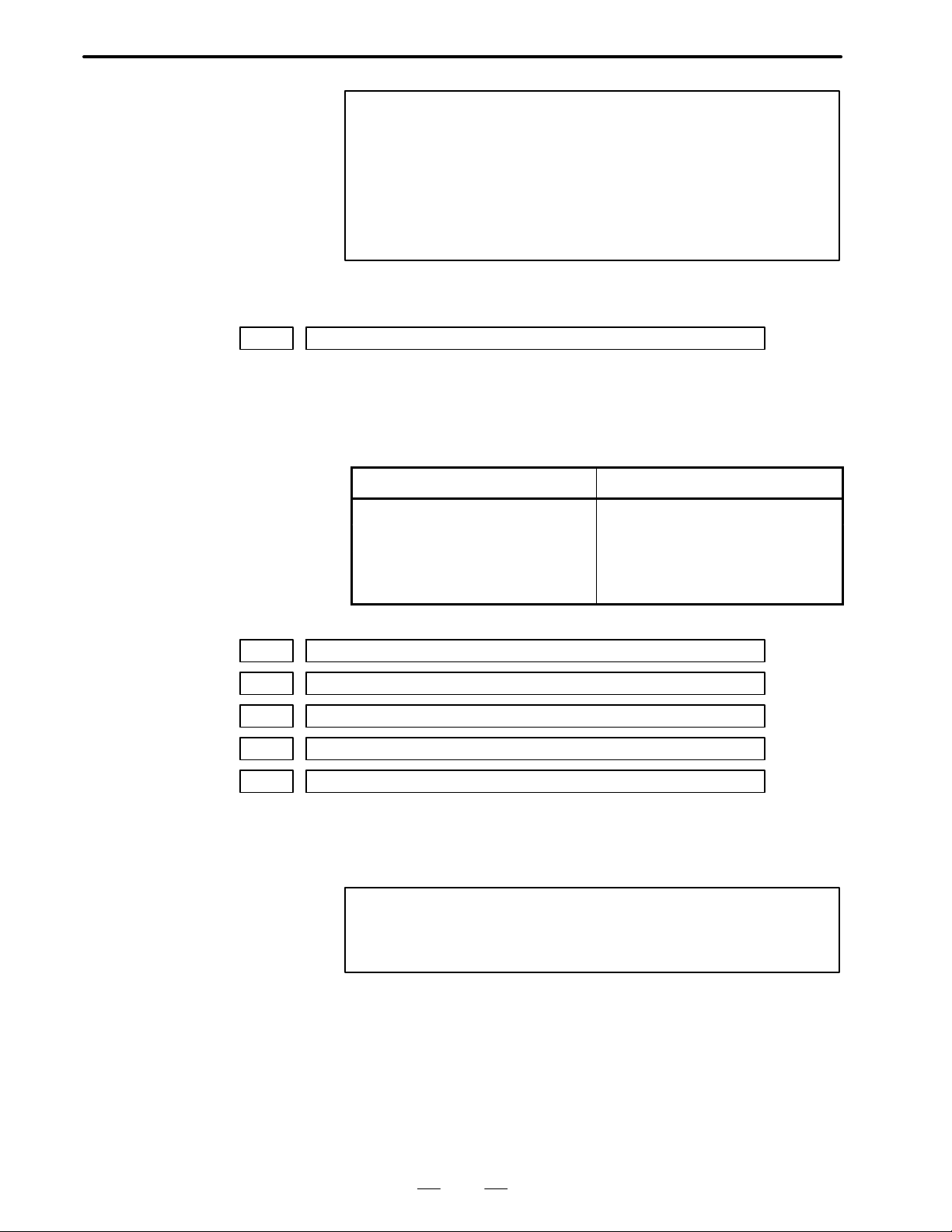
4. DESCRIPTION OF P ARAMETERS
POWER OFF
0350 Axis No. for controlling continuous feed without position loop
[Data type] Byte
[Data range] 0 to 3
B–62550EN/01
NOTE
1 See Character–to–codes Correspondence Table for setting
code.
2 Available character is numerals, alphabets, minus, period
and space.
3 When undefined characters are specified, they are
regarded as “space”.
Axis No. for controlling continuous feed without position loop by using
PMC axis control is set as follows.
Value Axis Name
0 No–axis
1 X–axis
2 Z–axis
3 3rd–axis
0351 Character code–1 of title
0352 Character code–2 of title
0353 Character code–3 of title
0354 Character code–4 of title
0355 Character code–5 of title
[Data type] Byte
The setting 5–characters are displayed on screen instead of program
number.
NOTE
See Connector–to–Codes Correspondence Table for
setting code.
54
Page 58

B–62550EN/01
4. DESCRIPTION OF P ARAMETERS
0356 Character length of 1st line on “DISTANCE TO GO” display
0357 Character length of 2nd line on “DISTANCE TO GO” display
0358 Character length of 3rd line on “DISTANCE TO GO” display
0359 Character length of 4th line on “DISTANCE TO GO” display
[Data type] Byte
[Data range] 0 to 11
Character lengths of 1st, 2nd, 3rd and 4th line which is displayed instead
of “DISTANCE TO GO” on program check screen are set respectively.
The display characters should be set on R–data on PMC.
#7
0385
#6
RTLIN
#5 #4 #3 #2 #1 #0
RTLIN 1 : Reference point return of rotary axis is treated as linear axis.
0 : Reference point return of rotary axis is treated as rotary axis.
#7
0386
#6
HDPIGB3#5HDPIGBZ#4HDPIGBX
#3 #2
HDPNEG3#1HDPNEGZ#0HDPNEGX
HDPNEGX 1 : X–axis motion of handle feed is inverse direction of handle rotation.
0 : X–axis motion of handle feed is same direction of handle rotation.
HDPNEGZ 1 : Z–axis motion of handle feed is inverse direction of handle rotation.
0 : Z–axis motion of handle feed is same direction of handle rotation.
HDPNEG3 1 : 3rd–axis motion of handle feed is inverse direction of handle rotation.
0 : 3rd–axis motion of handle feed is same direction of handle rotation.
HDPIGBX 1 : Handle multiplier of both MP1 and MP2 on is effective for X–axis.
0 : Handle multiplier of both MP1 and MP2 on is ineffective for X–axis.
HDPIGBZ 1 : Handle multiplier of both MP1 and MP2 on is effective for Z–axis.
0 : Handle multiplier of both MP1 and MP2 on is ineffective for Z–axis.
HDPIGB3 1 : Handle multiplier of both MP1 and MP2 on is effective for 3rd–axis.
0 : Handle multiplier of both MP1 and MP2 on is ineffective for
3rd–axis.
0387
#7
EFERPD
#6 #5 #4 #3 #2 #1 #0
EFERPD 1 : Rapid traverse rate for PMC axis control is specified in feedrate
command of PMC axis control.
0 : Rapid traverse rate for PMC axis control is same as rapid feedrate in
parameter.
55
Page 59

4. DESCRIPTION OF P ARAMETERS
B–62550EN/01
0388
#7
WKZSFT
#6
WKZRST#5IGNPS90
#4 #3
ROCNT#2RODRC#1ROAXC
#0
ROAXC 1 : Roll–over of absolute coordinate for rotary axis is available.
0 : Roll–over of absolute coordinate for rotary axis is not available.
RODRC 1 : Sign of command is regarded as direction when commanding
absolute value for rotary axis.
0 : Shorter motion is selected when commanding absolute value for
rotary axis.
ROCNT 1 : Roll–over of relative coordinate for rotary axis is available.
0 : Roll–over of relative coordinate for rotary axis is not available.
IGNPS90 1 : Alarm 90 is invalid.
0 : Alarm 90 is valid.
WKZRST 1 : Work coordinate is returned to G54 by NC reset.
0 : Work coordinate is not changed to G54 by NC reset.
WKZSFT 1 : W ork shift value and work zero offset value are treated as same values.
0 : Work shift value and work zero offset value are treated as different
values.
POWER OFF
0389
#7
#6 #5 #4 #3
TSKECR
#2
PRG8
#1 #0
SRVSET
SRVSET 1 : Servo tuning/setting screen is not displayed.
0 : Servo tuning/setting screen is displayed.
PRG8 1 : Editing of part program No. from 8000 to 8999 is protected.
0 : Editing of part program No. from 8000 to 8999 is not protected.
TSKECR 1 : Servo lag is not followed up when torque limit signals turns on by
using skip function with torque limit.
0 : Servo lag is followed up when torque limit signals turns on by using
skip function with torque limit.
#7
NODC30390
#6 #5 #4 #3 #2
NREQ3#1NREQZ#0NREQX
NREQX When machine coordinate of X–axis is not fixed at power–up with using
absolute pulse coder,
1 : no alarm is displayed.
0 : alarm 310 is displayed.
NREQZ When machine coordinate of Z–axis is not fixed at power–up with using
absolute pulse coder,
1 : no alarm is displayed.
0 : alarm 320 is displayed.
NREQ3 When machine coordinate of 3rd–axis is not fixed at power–up with using
absolu pulse coder,
1 : no alarm is displayed.
0 : alarm 330 is displayed.
56
Page 60

B–62550EN/01
4. DESCRIPTION OF P ARAMETERS
NODC3 1 : DC3 is not output until CNC buffer becomes full in DNC operation
with using reader/puncher interface channel–1 or –2.
0 : DC3 is output when EOB is read in DNC operation with using reader/
puncher interface channel–1 or –2.
#7
NOCLR0391
#6
RS23BN
#5 #4 #3 #2
JZRN3#1JZRNZ#0JZRNX
JZRNX 1 : Dogless reference point return of X–axis is not available.
0 : Dogless reference point return of X–axis is available.
NOTE
This parameter has meaning only when parameter 076#1
(JZRN) is set to “1”.
JZRNZ 1 : Dogless reference point return of Z–axis is not available.
0 : Dogless reference point return of Z–axis is available.
NOTE
This parameter has meaning only when parameter 076#1
(JZRN) is set to “1”.
JZRN3 1 : Dogless reference point return of 3rd–axis is not available.
0 : Dogless reference point return of 3rd–axis is available.
NOTE
This parameter has meaning only when parameter 076#1
(JZRN) is set to “1”.
RS23BN 1 : DC code is not used for controlling reader/puncher interface.
0 : DC code is used for controlling reader/puncher interface.
NOCLR 1 : Special G–codes are not cleared by reset operation.
0 : All G–codes are cleared by reset operation.
NOTE
This parameter has meaning only when parameter 045#6
(CLER) is set to “1”.
57
Page 61

4. DESCRIPTION OF P ARAMETERS
B–62550EN/01
0393
#7
DGNWEB
#6
RADCHK
#5
STOV0
#4
CHKMRC#3M3RQNG#2WKNOMDI
#1
MRCQSCH
#0
MRCQSCH When commanding multiple canned cycle,
1 : the existence of sequence No. specified by address Q is checked
before execution. (Alarm 63 appears.)
0 : the existence of sequence No. specified by address Q is not checked
before execution.
WKNOMDI 1 : Work zero offset can not be changed from MDI–key during feed–hold
or cycle start status.
0 : Work zero offset can be changed from MDI–key always.
M3RQNG 1 : 3–digit M–code causes alarm 003.
0 : 3–digit M–code is available.
CHKMRC When commanding multiple turning cycle G71, G72,
1 : alarm 64 appears when programming pocket–type profile.
0 : no alarm appears when programming pocket–type profile.
STOV0 1 : Feedrate override 0% stops rapid traverse (G00).
0 : Feedrate override 0% does not influence rapid traverse (G00).
RADCHK 1 : T olerance check of circle radius between start point and end point is
effective.
0 : Tolerance check of circle radius between start point and end point is
ineffective.
DGNWEB 1 : Changing PMC parameter from MDI key is allowed regardless of
PWE setting.
0 : Changing PMC parameter from MDI key is allowed only in PWE
setting = 1.
#7
CAKEY0394
#6
POSILK
#5 #4 #3 #2 #1
TFHOVR
#0
TFHOVR 1 : Rapid override is regarded as 100% during thread retract.
0 : Rapid override is same as usual during thread retract.
POSILK 1 : Interlock (STLK etc) is valid in not only auto mode but also manual
mode.
0 : Interlock (STLK etc) is valid in only auto mode.
CAKEY 1 : One charactor cancel by “CAN” key is available in parameter/DGN
and offset scre.
0 : One charactor cancel by “CAN” key is not available.
#7
0395
#6 #5 #4
ADDLA
#3 #2 #1
TLSCUR
#0
DLG99
DLG99 1 : Command unit of dwell (G04) in feed per rev. (G95) is spindle
revolution.
0 : Command unit of dwell (G04) in feed per rev. (G95) is second.
TLSCUR 1 : Cursor returns to the previous position when displaying offset screen
again.
0 : Cursor returns to top position when displaying offset screen again.
58
Page 62

B–62550EN/01
4. DESCRIPTION OF P ARAMETERS
ADDLA 1 : During tool nose radius compensation, if two blocks specifying no
movement are specified consecutively , the offset vector is assumed to
be the intersection vector.
0 : During tool nose radius compensation, if two blocks specifying no
movement are specified consecutively , the offset vector is assumed to
be the vector perpendicular to the movement performed in the
previous block at the end point.
#7
EORRE0396
#6 #5 #4 #3 #2
NCKER
#1 #0
NCKER 1 : The signal ER (RS–232–C) / TR (RS–422) is not checked.
0 : The signal ER (RS–232–C) / TR (RS–422) is checked.
EORRE When detecting EOB or % during auto operation,
1 : CNC turns to reset status internally.
0 : alarm 008 appears.
#7
SERNAI0397
#6 #5 #4 #3 #2
OVR255
#1 #0
OVR255 1 : Feedrate override is 1% unit.
0 : Feedrate override is 10% unit.
SERNAI 1 : Details of serial interface spindle alarm 409 are displayed on alarm
screen.
0 : Details of serial interface spindle alarm 409 are not displayed.
0399
#7
OUTZRN
#6
FEDNUL
#5 #4
FUNO
#3 #2 #1 #0
FUNO 1 : Absolute position is read from absolute pulse coder only after
detection error appears.
0 : Absolute position is read from absolute pulse coder after servo alarm
appears.
FEDNUL 1 : “NULL” code is output as feed data during meaning information.
0 : “SPACE” code is output as feed data during meaning information.
OUTZRN When reference point return is operated during feed–hold status,
1 : no alarm appears.
0 : alarm 91 appears.
POWER OFF
0452 Absolute counter value of X–axis at reference point
0453 Absolute counter value of Z–axis at reference point
0454 Absolute counter value of 3rd–axis at reference point
[Data type] Word
These parameters are set automatically when using absolute encoder with
serial interface.
59
Page 63

4. DESCRIPTION OF P ARAMETERS
0476 Stored address of 1st line charactors displayed on “DISTANCE TO GO”
0477 Stored address of 2nd line charactors displayed on “DISTANCE TO GO”
0478 Stored address of 3rd line charactors displayed on “DISTANCE TO GO”
0479 Stored address of 4th line charactors displayed on “DISTANCE T O GO”
[Data type] Word
[Data range] 300 to 699
0500 INPX
0501 INPZ
0502 INP3
B–62550EN/01
The stored addresses of 1st, 2nd, 3rd and 4th line which is displayed
instead of “DISTANCE TO GO” on program check screen are set.
INPX, INPZ, INP3 In–position width for X, Z and 3rd axis,respectively.
[Setting range] 0 to 32767 (detection unit)
In position check is performed when the feed mode changes from rapid
traverse to rapid traverse, rapid traverse to cutting feed, or cutting feed to
rapid traverse.
0504 SERRX
0505 SERRZ
0506 SERR3
SERRX, SERRZ, SERR3
Limitation value of position deviation amount during movement for X, Z
and 3rd axis, respectively.
[Setting range] 0 to 32767 (detection unit)
(Example)
When the rapid traverse rate is 10 m/min. and the position gain is 30,
the error is calculated by:Conversion of 10 m/min. into
F
E =
G
pulses/sec. with the detection unit of 1µ/pulse gives 166,666
pulses/sec. Therefore, E = 166,666/30 = 5,555 pulses. Multiply this
value by a factor of 1.5, and set the obtained value 8333 as the
parameter.
60
Page 64

B–62550EN/01
4. DESCRIPTION OF P ARAMETERS
POWER OFF
0508 GRDSX
0509 GRDSZ
0510 GRDS3
GRDSX, GRDSZ, GRDS3
Setting of grid shift amount of X, Z and 3rd axis, respectively.
[Setting range] 0 to "32767 (detect unit).
When the reference point is shifted, the sign of this parameter is necessary .
POWER OFF
0512 Position loop gain of X–axis
0513 Position loop gain of Z–axis
0514 Position loop gain of 3rd–axis
[Data type] Word
[Unit of data] 0.01 /sec
[Data range] 1 to 9999
Position loop gains of X, Z and 3rd–axis are set in order.
NOTE
0516 PSANGN
S4/S5 digits control (Analog output)
PSANGN Sets the data for adjusting the gain of constant surface speed control.
(analog output)
[Setting range] 700 to 1250
[Standard setting value] 1000
(Adjusting method)
(1)Set the standard setting value 1000.
(2)Designate the maximum S analog value (10V).
(3)Measure the output voltage.
(4)Set this value according to the following
(5)After setting the parameter, designate the maximum S analog value
These parameters are effective only when parameter 517
(position loop gain for all axes) is set to “0”.
10.0
Setting value =
1000
Measured voltage (V)
(10V) again, and make sure that the output voltage is 10V.
61
Page 65
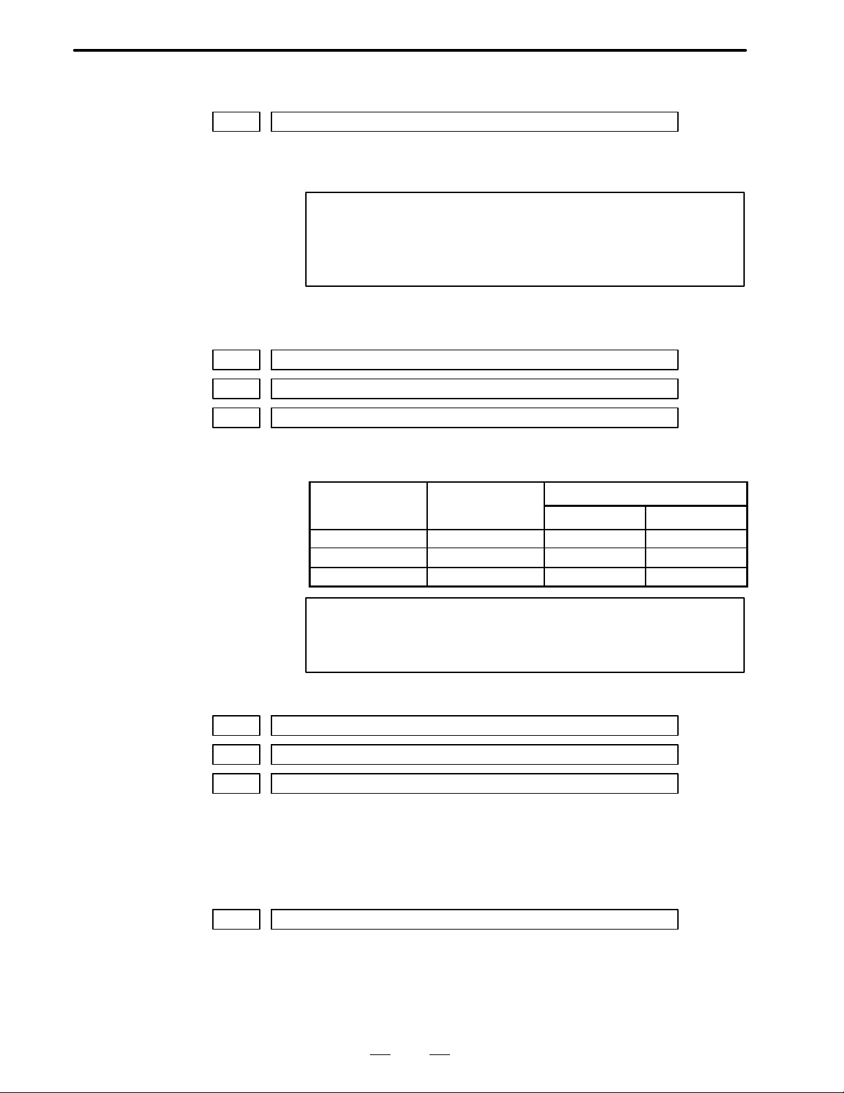
4. DESCRIPTION OF P ARAMETERS
Setting unit
Data unit
POWER OFF
0517 LPGIN
LPGIN Setting of servo loop gain in position control.
[Setting range] 1 to 9999 (unit: 0.01 sec)
0518 RPDFX
0519 RPDFZ
0520 RPDF3
B–62550EN/01
NOTE
T o set a loop gain to each axis, set No.517 to 0 and set a loop
gain of X axis, Y axis and so on. (The increment system is
the same.)
Remarks : Generally set 3000.
RPDFX, RPDFZ, RPDF3
Rapid traverse rate of X, Z and 3rd axes in turn.
[Data range]
[Data unit]
Millimeter machine 1 [mm/min] 30 to 24000 30 to 12000
NOTE
0522 LINTX
0523 LINTZ
0524 LINT3
LINTX, LINTZ, LINT3
Time constant of linear acceleration/deceleration of X, Z and 3rd axes in
turn during rapid traverse.
Data range
IS–A, IS–B IS–C
Inch machine
Rotation axis
0.1 [inch/min] 30 to 9600 30 to 4800
1 [deg/min] 30 to 24000 30 to 12000
Set “1” to the FML10 of parameter No.49 for the other
setting values.
[Setting range] 8 to 4000 (unit: msec.)
0526 THRDT
THRDT The time constant value of X axis in thread cutting cycle (G92).
[Setting range] 1 to 4000 (unit: msec.)
Set the most suitable value to this parameter in combination with the
parameter THDFL (parameter No. 0528).
62
Page 66

B–62550EN/01
Setting unit
Data unit
Setting unit
Data unit
Setting unit
Data unit
4. DESCRIPTION OF P ARAMETERS
0527 FEDMX
FEDMX Upper speed of cutting feed (available for X, Y, Z axes)
[Data range]
[Data unit]
IS–A, IS–B IS–C
Millimeter machine 1 [mm/min] 6 to 15000 6 to 12000
Inch machine
Rotation axis
0.1 [inch/min] 6 to 6000 6 to 4800
1 [deg/min] 6 to 15000 6 to 12000
Data range
NOTE
Set “1” to the FML10 of parameter No.49 for the other
cutting values.
0528 THDFL
THDFL The lower limit value (FL) of X axis acceleration/deceleration in thread
cutting cycle. (G92)
[Data range]
[Data unit]
IS–A, IS–B IS–C
Millimeter machine 1 [mm/min] 6 to 15000 6 to 12000
Inch machine
Rotation axis
0.1 [inch/min] 6 to 6000 6 to 4800
1 [deg/min] 6 to 15000 6 to 12000
Data range
Set the most suitable value to this parameter in consideration of the
parameter No.0526.
NOTE
In increment system the unit is the same
Remarks: See parameter No. 0526.
0529 FEEDT
FEEDT Time constant of the exponential acceleration/deceleration in cutting feed
and jog feed.
[Setting range] 0 to 4000 unit: msec Set this to “0”, when the exponential acceleration/
deceleration is not used.
0530 FEDFL
FEDFL The lower feed rate in exponential acceleration/deceleration.
[Data range]
[Data unit]
IS–A, IS–B IS–C
Millimeter machine 1 [mm/min] 6 to 15000 6 to 12000
Inch machine
Rotation axis
0.1 [inch/min] 6 to 6000 6 to 4800
1 [deg/min] 6 to 15000 6 to 12000
Data range
63
Page 67

4. DESCRIPTION OF P ARAMETERS
Setting unit
Data unit
Setting unit
Data unit
0533 RPDFL
RPDFL The least speed of rapid traverse override (Fo)
B–62550EN/01
(Common to all axes)
[Data range]
[Data unit]
Millimeter machine 1 [mm/min] 6 to 15000 6 to 12000
Inch machine
Rotation axis
0534 ZRNFL
0.1 [inch/min] 6 to 6000 6 to 4800
1 [deg/min] 6 to 15000 6 to 12000
IS–A, IS–B IS–C
Data range
ZRNFL Low feed speed at reference point return (FL) (Common to all axes)
[Data range]
[Data unit]
Millimeter machine 1 [mm/min] 6 to 15000 6 to 12000
Inch machine
Rotation axis
0535 BKLX
0536 BKLZ
0537 BKL3
0.1 [inch/min] 6 to 6000 6 to 4800
1 [deg/min] 6 to 15000 6 to 12000
IS–A, IS–B IS–C
Data range
BKLX, BKLZ, BKL3
[Data unit]
0539 SPDLC
SPDLC Sets the spindle speed offset compensation value, that is, compensation
[Setting range] 0 to +8191
Backlash amount of X, Z and 3rd axes, respectively.
Setting unit IS–A IS–B IS–C
Millimeter machine [mm] 0.01 0.001 0.0001
Inch machine [inch] 0.001 0.0001 0.00001
Rotation axis [deg] 0.01 0.001 0.0001
In diameter programming, set the value of X axis in diameter value.
NOTE
Set a backlash compensation value with a detection unit
when an arbitrary command multiply is used.
value of zero offset of spindle speed command voltage. (for constant
surface speed control)
(unit: VELO)
64
Page 68

B–62550EN/01
Gear number
Setting unit
Data unit
4. DESCRIPTION OF P ARAMETERS
0540 GRMX1
0541 GRMX2
0542 GRMX3
0543 GRMX4
GRMX1 to 4 The spindle speed corresponding to gears 1 to 4 when the spindle speed
command is 10V.(for constant surface speed control)
[Data range]
[Data unit]
Data unit [RPM] 10 [RPM]
Data range 1 to 19999 1 to 9999
1 [deg/min] 30 to 24000 30 to 12000
NOTE
Switch the gear at using signals (G1 18#2 GR1 and G118#3
GR2).
G118
#3 GR2 #2 GR1
0 0 1
0 1 2
1 0 3
1 1 4
0548 JOGFL
No. 0062#3 SMPRPM
0 1
JOGFL
[Data range]
[Data unit]
Data range
IS–A, IS–B IS–C
Millimeter machine 1 [mm/min] 6 to 15000 6 to 12000
Inch machine
Rotation axis
0.1 [inch/min] 6 to 6000 6 to 4800
1 [deg/min] 6 to 15000 6 to 12000
Specifies the FL feedrate used during manual–feed exponential
acceleration/deceleration for all axes.
NOTE
The FL feedrate can be specified for each axis separately,
using parameter No.0605 to 0608.
65
Page 69
4. DESCRIPTION OF P ARAMETERS
0550 SEQINC
SEQINC Number increment value in automatic insertion of equence No.
[Setting range] 0 to 9999
0551 LOWSP
LOWSP Minimum spindle speed in constant surface speed control mode (G96)
B–62550EN/01
NOTE
This parameter is enabled when setting parameter SEQ =
1.
[Data range]
[Data unit]
Data unit [RPM] 10 [RPM]
Data range 1 to 19999 1 to 9999
1 [deg/min] 30 to 24000 30 to 12000
0552 BRA TE0
No. 0062#3 SMPRPM
0 1
BRA TE0 This sets the baud rate when the reader/puncher interface is used.
(Effective when the setting parameter I/O is 0.)
Relation between the setting value and the baud rate is as follows:
Setting value Baud rate
1 50
2 100
3 110
4 150
5 200
6 300
7 600
8 1200
9 2400
10 4800
11 9600
66
Page 70

B–62550EN/01
4. DESCRIPTION OF P ARAMETERS
0553 BRA TE1
BRATE1 This sets the baud rate when the reader/puncher interface is used.
(Effective when the setting parameter I/O is 1.)
Relation between the setting value and the baud rate is as follows:
Setting value Baud rate
1 50
2 100
3 110
4 150
5 200
6 300
7 600
8 1200
9 2400
10 4800
11 9600
0555 Feedrate ratio at which the next block is started for block overlap
[Unit of data] %
[Data range] 0 to 100
For rapid traverse block overlap, the feedrate ratio at which the next block
will be started is set. If this parameter is set to 80, the next block is started
once the feedrate has decelerated to 80% at the end point of the current
block. The value to be set is determined using the following formula:
Current block feedrate at which next block is started
= Specified current block feedrate set value/100
NOTE
If the parameter is set to 100, the next block is started upon
the start of deceleration for the current block.
0556 SCLMP
SCLMP Upper limit of spindle speed (for constant surface speed control)
[Data range]
[Data unit]
No. 0062#3 SMPRPM
0 1
Data unit [RPM] 10 [RPM]
Data range 1 to 19999 1 to 9999
1 [deg/min] 30 to 24000 30 to 12000
67
Page 71

4. DESCRIPTION OF P ARAMETERS
Setting unit
Data unit
0557 CRCDL
CRCDL When tool moves along the outside of an acute angle close to 90° during
B–62550EN/01
tool nose radius compensation, limitations on ignoring a small movement
amount.
[Data unit]
Setting unit IS–A IS–B IS–C
Millimeter machine [mm] 0.01 0.001 0.0001
Inch machine [inch] 0.001 0.0001 0.00001
Rotation axis [deg] 0.01 0.001 0.0001
∆X
∆Y
(1)
90° > α
(2)
0559 RPDJX
0560 RPDJZ
0561 RPDJ3
RPDJX, RPDJZ, RPDJ3
Rapid traverse rate in JOG mode for X, Z and 3rd axis in turn.
[Data range]
[Data unit]
Millimeter machine 1 [mm/min] 6 to 15000 6 to 12000
If “0” is set to these parameters, the set values of parameter No.0518,
0519, 0520 and 0521 are used.
If both ∆X and ∆Y are less than the set value, vector (2) is ignored.
Data range
IS–A, IS–B IS–C
Inch machine
Rotation axis
0.1 [inch/min] 6 to 6000 6 to 4800
1 [deg/min] 6 to 15000 6 to 12000
68
Page 72

B–62550EN/01
4. DESCRIPTION OF P ARAMETERS
NOTE
Set the FML10 of parameter No.49 to 1 for the other setting
values.
POWER OFF
0570 Capacity of reference counter for X–axis
0571 Capacity of reference counter for Z–axis
0572 Capacity of reference counter for 3rd–axis
[Data type] Word
[Data range] 0 to 32767
Capacities of reference counter for X, Z and 3rd–axis are set in order.
NOTE
1 The setting value is multiplied with 10 when using high
resolution pulse coder.
2 Parameter 004 to 006 are valid when the these parameters
are set to “0”.
3 It is necessary to turn off CNC power after changing these
parameters.
0593 STPEX
0594 STPEZ
0595 STPE3
STPEX, Z, 3 Position error limit value during X–axis, Z–axis, and 3rd axis stop in
sequence
[Setting value] 0 to 32767
[Data unit ] Detecting unit
0600 PARTRQ
PARTRQ Sets the number of machined parts required.
[Setting value] 0 to 9999
0601 PEXPJX
0602 PEXPJZ
0603 PEXPJ3
PEXPJX– PEXPJ3 Sets exponential acceleration/deceleration time constant sequentially in
manual feed.
[Setting value] 0 to 4000
69
Page 73
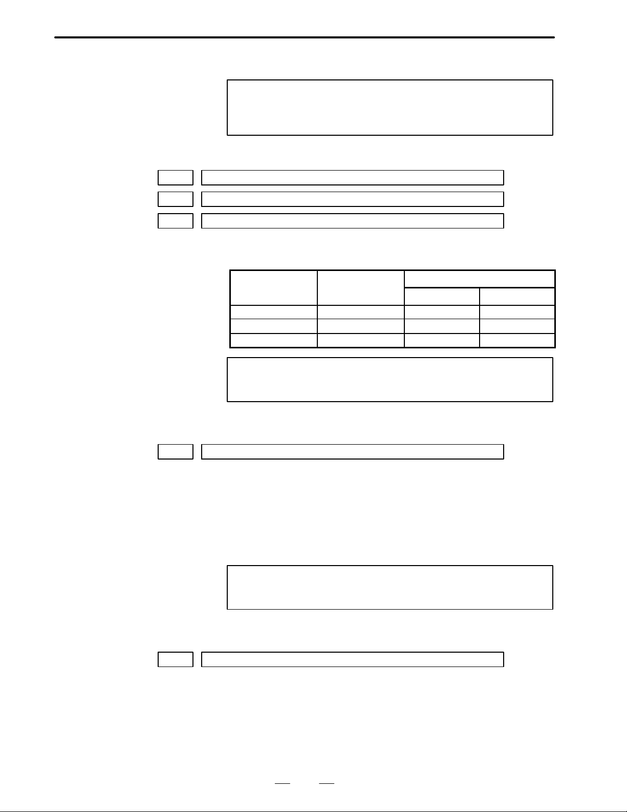
4. DESCRIPTION OF P ARAMETERS
Setting unit
Data unit
[Unit] msec
0605 PFLJGX
0606 PFLJGZ
0607 PFLJG3
PFLJGX–PFLJG3 Sets exponential acceleration/ deceleration rate sequentially in manual
B–62550EN/01
NOTE
If 0 is set then cutting feed and common data (PRM529) is
used.
feed.
[Data range]
[Data unit]
Millimeter machine 1 [mm/min] 6 to 15000 6 to 12000
NOTE
POWER OFF
0613 PSANG2
PSANG2 S4/S5 digit control (analog output)
Set the data for gain adjustment of the 2nd spindle in the data analog
output for gain adjustment of constant surface speed control (analog
output).
[Set range] 700 – 1250
[Standard set value] 1000
Data range
IS–A, IS–B IS–C
Inch machine
Rotation axis
0.1 [inch/min] 6 to 6000 6 to 4800
1 [deg/min] 6 to 15000 6 to 12000
If 0 is set then all axes common data (PRM548) is used.
NOTE
Refer to the parameter No.516.
POWER OFF
0614 SPDLC2
SPDLC2 Set the 2nd spindle speed offset compensation value, that is, the zero
offset compensation value of spindle speed command voltage.
[Set value] 0 – "8191
[Unit] VELO
70
Page 74

B–62550EN/01
4. DESCRIPTION OF P ARAMETERS
POWER OFF
0615 G2MAX1
0616 G2MAX2
G2MAX1, 2 Speeds of the 2nd spindle corresponding to the gears 1 and 2 when the
spindle speed command is 10V.
[Data range]
[Data unit]
POWER OFF
0617 PSANG3
PSANG3 S4/S5 digit control (analog output)
Set the data for gain adjustment of the 3rd spindle in the data analog output
for gain adjustment of constant surface speed control (analog output).
[Set range] 700 – 1250
[Standard set value] 1000
NOTE
0618 SPDLC3
No. 0062#3 SMPRPM
0 1
Data unit [RPM] 10 [RPM]
Data range 1 to 19999 1 to 9999
1 [deg/min] 30 to 24000 30 to 12000
Refer to the parameter No.516.
SPDLC3 Set the 3rd spindle speed offset compensation value, that is the zero offset
compensation value of spindle speed command voltage.
[Set value] 0 – "8191
[Unit] VELO
0619 G3MAX1
0620 G3MAX2
G3MAX1, 2 Speeds of the 3rd spindle corresponding to the gears 1 and 2 when the
spindle speed command is 10V.
[Data range]
[Data unit]
Data unit [RPM] 10 [RPM]
Data range 1 to 19999 1 to 9999
1 [deg/min] 30 to 24000 30 to 12000
No. 0062#3 SMPRPM
0 1
71
Page 75

4. DESCRIPTION OF P ARAMETERS
Setting unit
Data unit
Setting unit
Data unit
0627 Time constant of Z–axis acc/dec in threading cycle
[Data type] Word
[Unit of data] msec
[Data range] 0 to 4000
0628 FL speed of Z–axis acc/dec in threading cycle
[Data type] Word
B–62550EN/01
Time constant of Z–axis exponential acc/dec in threading cycle is set.
[Data range]
[Data unit]
IS–A, IS–B IS–C
Millimeter machine 1 [mm/min] 6 to 15000 6 to 12000
Inch machine
0.1 [inch/min] 6 to 6000 6 to 4800
Data range
FL speed of Z–axis exponential acc/dec in threading cycle is set.
0651 PEFDTX
0652 PEFDTZ
0653 PEFDT3
PEFDTX – 3 Time constants of exponential acceleration/ deceleration of PMC axis
cutting feed for each axis.
[Set value] 0 – 4000
[Unit] msec
NOTE
When 0 is set, the data for NC (PRM No.529) is used.
0657 PEAFLX
0658 PEAFLZ
0659 PEAFL3
PEAFLX – 3 Lower limit speeds (FL) at exponential acceleration/deceleration of PMC
axis cutting feed for each axis.
[Data range]
[Data unit]
IS–A, IS–B IS–C
Millimeter machine 1 [mm/min] 6 to 15000 6 to 12000
Inch machine
Rotation axis
0.1 [inch/min] 6 to 6000 6 to 4800
1 [deg/min] 6 to 15000 6 to 12000
72
Data range
Page 76

B–62550EN/01
Setting unit
Data unit
Setting unit
Data unit
4. DESCRIPTION OF P ARAMETERS
NOTE
When 0 is set, the cutting FL speed for NC (PRM No.530)
is used.
0672 FL speed of reference point return by PMC axis control
[Data type] Word
[Data range]
[Data unit]
Millimeter machine 1 [mm/min] 6 to 15000 6 to 12000
Inch machine
Rotation axis
0.1 [inch/min] 6 to 6000 6 to 4800
1 [deg/min] 6 to 15000 6 to 12000
IS–A, IS–B IS–C
FL speed of reference point return by PMC axis control is set. When “0” is
set, parameter 534 is used for FL speed of PMC axis control.
0673 Backlash compensation value for rapid traverse for X–axis
0674 Backlash compensation value for rapid traverse for Y–axis
0675 Backlash compensation value for rapid traverse for 3rd axis
[Data unit]
Increment unit IS–A IS–B IS–C
Millimeter machine [mm] 0.01 0.001 0.0001
Inch machine [inch] 0.001 0.0001 0.00001
[Data range] 0 to 2550
The backlash compensation value for rapid traverse is set for each axis.
Data range
0685 F0 speed of PMC axis control with using independent rapid override
[Data type] Word
[Data range]
[Data unit]
IS–A, IS–B IS–C
Millimeter machine 1 [mm/min] 6 to 15000 6 to 12000
Inch machine
Rotation axis
0.1 [inch/min] 6 to 6000 6 to 4800
1 [deg/min] 6 to 15000 6 to 12000
Data range
F0 speed of PMC axis control is set when using override independent of
CNC axis control.
NOTE
This parameter is effective when setting both parameter
078#7 (EAXOVE) and 078#6 (RDRNE) are set to “1”.
73
Page 77

4. DESCRIPTION OF P ARAMETERS
Setting unit
Data unit
0698 Maximum feedrate per revolution by PMC axis control
[Data type] Word
B–62550EN/01
[Data range]
[Data unit]
Millimeter machine 1 [mm/min] 6 to 15000 6 to 12000
Inch machine
Rotation axis
0.1 [inch/min] 6 to 6000 6 to 4800
1 [deg/min] 6 to 15000 6 to 12000
Maximum feedrate per revolution by PMC axis control is set.
0699 Multiplier for handle feed
[Data type] Word
[Data range] 0 to "1000
The multiplier of handle feed with both handle motion select signals MP1
and MP2 on is set. When minus value is specified, the actual motion is
opposite of handle direction.
NOTE
When “0” is specified, parameter 121 becomes effective
instead of this parameter.
Data range
IS–A, IS–B IS–C
0700 LT1X1
0701 LT1Z1
0702 LT131
0704 LT1X2
0705 LT1Z2
0706 LT132
LT1
nth top in square zone (see figure).
axis
2
Set stroke limit mentioned above.
[Data unit]
Setting unit IS–A IS–B IS–C
Millimeter machine [mm] 0.01 0.001 0.0001
Inch machine [inch] 0.001 0.0001 0.00001
1
74
Page 78

B–62550EN/01
4. DESCRIPTION OF P ARAMETERS
[Data range] 0 to "99999999
Set with the distance from the reference point.
In the case of diameter designation, set with the diameter designation
value.
The outside of the boundary set with the parameter is set as the inhibited
region. Normally, set at the max. stroke of the machine.
When the axis enters the inhibited region, overtravel alarm is indicated.
A margin should be provided with respect to the stroke to cope with the
fluctuation in the detecting operation. As a rule, in the case of metric
designation, multiply the rapid traverse by a factor of 1/5 and set it as the
margin.
Example) Rapid traverse 10 m/min.
10 1/5 = 2 mm
The actual position of the machine slightly differs from the position stored
in the CNC unit after the power is turned on, emergency stop is reset, or
servo alarm is reset. Therefore, before starting operation, be sure to return
the axes to reference point. Otherwise, overtravel detecting position
deviates by the value corresponding to the above–described deviation in
the position.
When the parameters are set as follows, the stroke limit becomes infinite.
LT1 1<L T12
Axis name
Example) LT1Z1 = –1 and LT1Z2 = 1
the Z axis stroke becomes infinite.
NOTE
1 For the axis whose stroke is infinite, the incremental
command can be specified. If the absolute command is
specified, the absolute register may overflow and it is not
operated normally.
2 These parameters cannot be set for the rotary axis.
0708 PRSX
0709 PRSZ
0710 PRS3
PRSX, PRSZ, PRS3 These set the coordinate values of the reference point of the X, Z and 3rd
axes when automatic coordinate system setting is conducted,
respectively.
[Data unit]
Setting unit IS–A IS–B IS–C
Millimeter machine [mm] 0.01 0.001 0.0001
Inch machine [inch] 0.001 0.0001 0.00001
Rotation axis [deg] 0.01 0.001 0.0001
75
Page 79

4. DESCRIPTION OF P ARAMETERS
0717 MRCCD
MRCCD Depth of cut in multiple repetitive cycle G71, G72.
B–62550EN/01
[Data unit]
Setting unit IS–A IS–B IS–C
Millimeter machine [mm] 0.01 0.001 0.0001
Inch machine [inch] 0.001 0.0001 0.00001
[Data range] 0 to 99999999
0718 MRCDT
MRCDT Relief amount in multiple repetitive cycle G71, G72.
[Data unit]
Setting unit IS–A IS–B IS–C
Millimeter machine [mm] 0.01 0.001 0.0001
Inch machine [inch] 0.001 0.0001 0.00001
[Data range] 1 to 99999999
0719 PESCX
0720 PESCZ
PESCX, PESCZ Relief values in X and Z directions in multiple repetitive cycle G73,
respectively.
[Data unit]
Setting unit IS–A IS–B IS–C
Millimeter machine [mm] 0.01 0.001 0.0001
Inch machine [inch] 0.001 0.0001 0.00001
[Data range] 0 to "99999999
0721 PATIM
PATIM Number of divisions in multiple repetitive cycle G73.
[Setting range] 1 to 99999999
0722 GROVE
GROVE Return amount in multiple repetitive cycle G74, G75.
[Data unit]
Setting unit IS–A IS–B IS–C
Millimeter machine [mm] 0.01 0.001 0.0001
Inch machine [inch] 0.001 0.0001 0.00001
[Data range] 0 to 99999999
0723 THRPT
THRPT Number of repetitions of final finishing in multiple repetitive cycle G76.
[Setting range] 1 to 99999999
76
Page 80
B–62550EN/01
4. DESCRIPTION OF P ARAMETERS
0724 THANG
THANG Tool nose angle in multiple repetitive cycle G76.
[Setting value] 0, 29, 30, 55, 60, 80
0725 THCLM
THCLM Minimum depth of cut in multiple repetitive cycle G76.
[Data unit]
Setting unit IS–A IS–B IS–C
Millimeter machine [mm] 0.01 0.001 0.0001
Inch machine [inch] 0.001 0.0001 0.00001
[Data range] 0 to "99999999
0726 THDFN
THDFN Finishing allowance in multiple repetitive cycle G76
[Data unit]
Setting unit IS–A IS–B IS–C
Millimeter machine [mm] 0.01 0.001 0.0001
Inch machine [inch] 0.001 0.0001 0.00001
[Data range] 0 to "99999999
0728 WIMAX
WIMAX Sets the tolerance value of tool wear offset incremental input.
[Data unit]
Setting unit IS–A IS–B IS–C
Millimeter machine [mm] 0.01 0.001 0.0001
Inch machine [inch] 0.001 0.0001 0.00001
[Data range] 1 to 999999
0729 WOMAX
WOMAX Sets the maximum of the tool wear offset value.
[Data unit]
Setting unit IS–A IS–B IS–C
Millimeter machine [mm] 0.01 0.001 0.0001
Inch machine [inch] 0.001 0.0001 0.00001
[Data range] 1 to 99999999
0735 2nd reference point of X axis
0736 2nd reference point of Z axis
0737 2nd reference point of 3rd axis
[Data type] 2 words
77
Page 81

4. DESCRIPTION OF P ARAMETERS
B–62550EN/01
[Data unit]
Setting unit IS–A IS–B IS–C
Millimeter machine [mm] 0.01 0.001 0.0001
Inch machine [inch] 0.001 0.0001 0.00001
Rotation axis [deg] 0.01 0.001 0.0001
[Data range] 0 to "99999999
2nd reference point of 3rd and 4th axis are set in order.
POWER OFF
0739 Counter value of absolute pulse coder for X axis at reference point
0740 Counter value of absolute pulse coder for Z axis at reference point
0741 Counter value of absolute pulse coder for 3rd–axis at reference point
[Data type] 2 words
[Data unit] Detection unit
[Data range] –2147483648 to 2147483647 (only the lower 8 digits are displayed)
Counter values of absolute pulse coder for 3rd axis at reference point are
set automatically after manual reference point return is finished with
using absolute pulse coder.
POWER OFF
0756 PECINTX
0757 PECINTZ
0758 PECINT3
PECINTX, PECINTZ, PECINT3
Compensation intervals at pitch error compensation of each axis.
[Setting value] When the radius is designated
8000 – 99999999 (Metric output)
4000 – 99999999 (Inch output)
However, set in diameter value for the diameter designated axis.
When the diameter is designated
16000 – 99999999 (Metric output)
8000 – 99999999 (Inch output)
[Data unit]
Setting unit IS–A IS–B IS–C
Millimeter machine [mm] 0.01 0.001 0.0001
Inch machine [inch] 0.001 0.0001 0.00001
Rotation axis [deg] 0.01 0.001 0.0001
78
Page 82
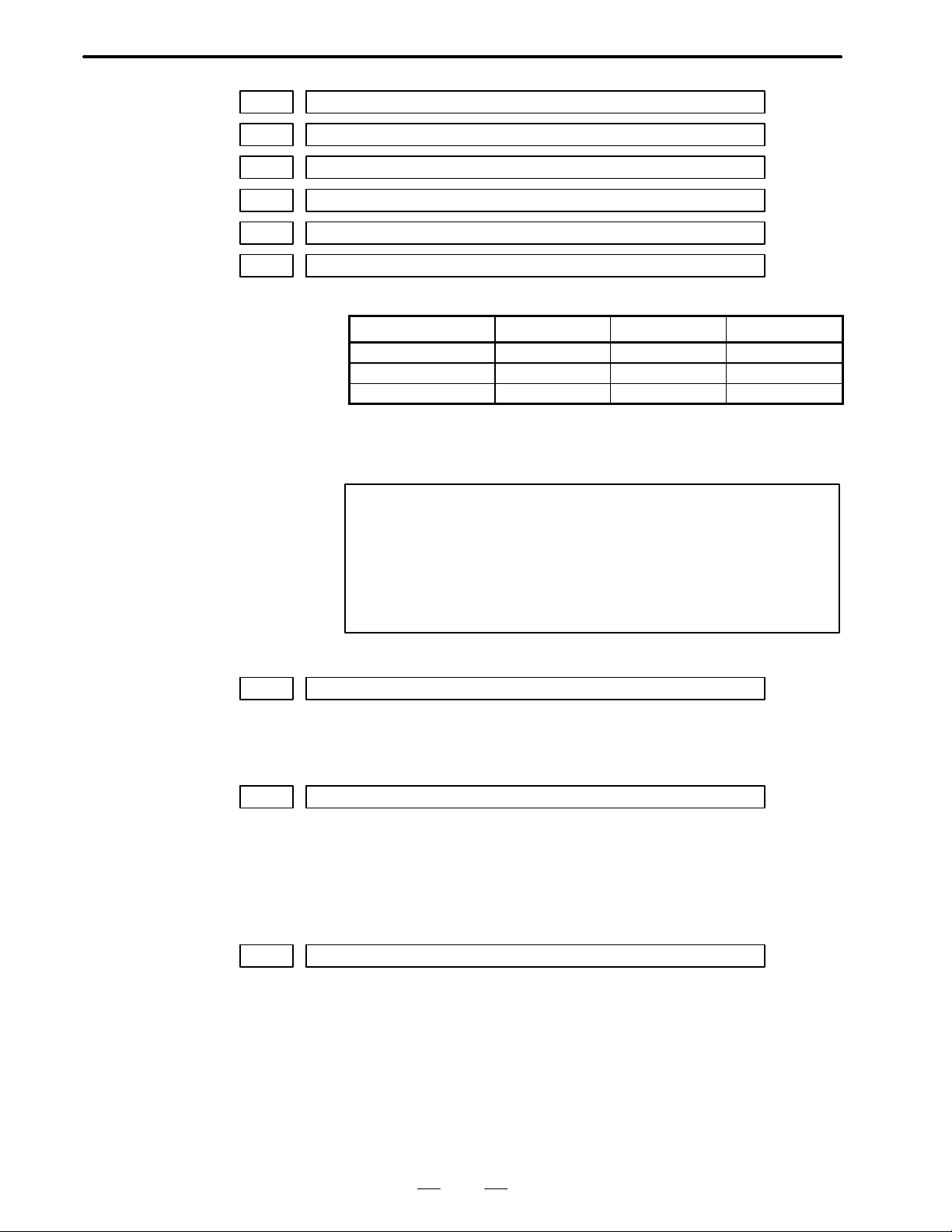
B–62550EN/01
4. DESCRIPTION OF P ARAMETERS
0770 Plus side of stored stroke limit–2 for X–axis
0771 Plus side of stored stroke limit–2 for Z–axis
0772 Plus side of stored stroke limit–2 for 3rd–axis
0774 Minus side of stored stroke limit–2 for X–axis
0775 Minus side of stored stroke limit–2 for Z–axis
0776 Minus side of stored stroke limit–2 for 3rd–axis
[Data type] 2 words
[Data unit]
Setting unit IS–A IS–B IS–C
Millimeter machine [mm] 0.01 0.001 0.0001
Inch machine [inch] 0.001 0.0001 0.00001
Rotation axis [deg] 0.01 0.001 0.0001
[Data range] 0 to "99999999
Plus side and minus side of stored stroke limit–2 for X, Z and 3rd axis are
set.
NOTE
1 When signal G129#6 (EXLM1) is on, these parameters are
refered as sotred stroke limit instead of parameter 700 to
707.
2 These parameters are valid only when parameter 020#4
LM2 is set to “1”.
0779 PARTAL
PARTAL No. of machined parts in total
[Setting value] 0 to 99999999
0788 Movement of rotary axis per one revolution
[Data type] 2 words
[Data unit] input increment
[Data range] 1000 to 10000000
Movement of rotary axis per one revolution is set for roll–over function.
0797 Lock for displaying part program No.9000 to 9999
[Data type] 2 words
[Data range] 0 to 99999999
A number is set to prohibit displaying part programs which program
number is from 9000 to 9999. This parameter is effective only when
010#4 (PRG9) is set to “1”. Parameter PRG9 can not be turned to “0”
unless parameter 798 is coincident with the parameter.
Setting value “0” means no lock is available.
The actual setting value is not displayed.
79
Page 83

4. DESCRIPTION OF P ARAMETERS
0798 Key for displaying part program No.9000 to 9999
[Data type] 2 words
[Data range] 0 to 99999999
0815 Auto–preset coordinate value of X–axis after reference point return
0816 Auto–preset coordinate value of Z–axis after reference point return
0817 Auto–preset coordinate value of 3rd–axis after reference point return
[Data type] 2 words
B–62550EN/01
Parameter PRG9 can be turned to “0” if the same number as parameter 797
is set in this parameter.
The actual setting value is not displayed too.
[Data unit]
Setting unit IS–A IS–B IS–C
Millimeter machine [mm] 0.01 0.001 0.0001
Inch machine [inch] 0.001 0.0001 0.00001
Rotation axis [deg] 0.01 0.001 0.0001
[Data range] 0 to "99999999
Auto–preset corrdinate values of X, Z and 3rd–axis after reference point
return are set respectively.
NOTE
These parameters are valid only when parameter 063#1
PRSTIN is set to “1” with inch input.
0876 Tolerance of circle radius between start point and end point
[Data type] 2 words
[Data unit] input increment
[Data range] 0 to 99999999
The tolerance of circle radius between start point and end point is set.
When the difference of radius between start point and end point exceeds
the specified value, alarm 20 will appear.
0940 External work zero offset of X–axis
0941 External work zero offset of Z–axis
0942 External work zero offset of 3rd–axis
[Data type] 2 words
[Data unit]
Setting unit IS–A IS–B IS–C
Millimeter machine [mm] 0.01 0.001 0.0001
Inch machine [inch] 0.001 0.0001 0.00001
Rotation axis [deg] 0.01 0.001 0.0001
80
Page 84
B–62550EN/01
4. DESCRIPTION OF P ARAMETERS
[Data range] 0 to "7999
External work zero offset values of X, Z and 3rd axis are set in order.
0944 1st work zero offset value of X–axis (G54)
0945 1st work zero offset value of Z–axis (G54)
0946 1st work zero offset value of 3rd–axis (G54)
[Data type] 2 words
[Data unit]
Setting unit IS–A IS–B IS–C
Millimeter machine [mm] 0.01 0.001 0.0001
Inch machine [inch] 0.001 0.0001 0.00001
Rotation axis [deg] 0.01 0.001 0.0001
[Data range] 0 to "99999999
1st work zero offset values of X, Z and 3rd axis are set in order.
0948 2nd work zero offset value of X–axis (G55)
0949 2nd work zero offset value of Z–axis (G55)
0950 2nd work zero offset value of 3rd–axis (G55)
[Data type] 2 words
[Data unit]
Setting unit IS–A IS–B IS–C
Millimeter machine [mm] 0.01 0.001 0.0001
Inch machine [inch] 0.001 0.0001 0.00001
Rotation axis [deg] 0.01 0.001 0.0001
[Data range] 0 to "99999999
2nd work zero offset values of X, Z and 3rd axis are set in order.
0952 3rd work zero offset value of X–axis (G56)
0953 3rd work zero offset value of Z–axis (G56)
0954 3rd work zero offset value of 3rd–axis (G56)
[Data type] 2 words
[Data unit]
Setting unit IS–A IS–B IS–C
Millimeter machine [mm] 0.01 0.001 0.0001
Inch machine [inch] 0.001 0.0001 0.00001
Rotation axis [deg] 0.01 0.001 0.0001
[Data range] 0 to "99999999
3rd work zero offset values of X, Z, 3rd and 4th axis are set in order.
81
Page 85
4. DESCRIPTION OF P ARAMETERS
0956 4th work zero offset value of X–axis (G57)
0957 4th work zero offset value of Z–axis (G57)
0958 4th work zero offset value of 3rd–axis (G57)
[Data type] 2 words
B–62550EN/01
[Data unit]
Setting unit IS–A IS–B IS–C
Millimeter machine [mm] 0.01 0.001 0.0001
Inch machine [inch] 0.001 0.0001 0.00001
Rotation axis [deg] 0.01 0.001 0.0001
[Data range] 0 to "99999999
4th work zero offset values of X, Z and 3rd axis are set in order.
0960 5th work zero offset value of X–axis (G58)
0961 5th work zero offset value of Z–axis (G58)
0962 5th work zero offset value of 3rd–axis (G58)
[Data type] 2 words
[Data unit]
Setting unit IS–A IS–B IS–C
Millimeter machine [mm] 0.01 0.001 0.0001
Inch machine [inch] 0.001 0.0001 0.00001
Rotation axis [deg] 0.01 0.001 0.0001
[Data range] 0 to "99999999
5th work zero offset values of X, Z and 3rd axis are set in order.
0964 6th work zero offset value of X–axis (G59)
0965 6th work zero offset value of Z–axis (G59)
0966 6th work zero offset value of 3rd–axis (G59)
[Data type] 2 words
[Data unit]
Setting unit IS–A IS–B IS–C
Millimeter machine [mm] 0.01 0.001 0.0001
Inch machine [inch] 0.001 0.0001 0.00001
Rotation axis [deg] 0.01 0.001 0.0001
[Data range] 0 to "99999999
6th work zero offset values of X, Z and 3rd axis are set in order.
82
Page 86

B–62550EN/01
4. DESCRIPTION OF P ARAMETERS
Setting pitch error compensation
Setting the pitch error
compensation interval
Pitch error compensation points are located at equal intervals, specified
for each axis. Pitch error compensation is performed at the midpoint of
each compensation interval. (See the following figure.)
Compensation
value
+3
+2
+1
34 35 36 3733323130
Reference
position
–1
–2
Compensation point number
Compensation
interval
30 31 32 33 34 35 36 37
Compensation
point number
Set compensation value –2 +3 –1 –1 +1 +2 –1 –3
If the compensation interval is set to 0, pitch error compensation is not
performed for that axis. The minimum interval between pitch error
compensation points is limited to the following value:
Minimum pitch error compensation interval = Maximum rapid traverse rate/1875
Example:
When the maximum rapid traverse rate is 15000 mm/min, the
minimum interval between pitch error compensation points is 8 mm.
0756 Compensation interval for X–axis pitch error compensation
0757 Compensation interval for Z–axis pitch error compensation
0758 Compensation interval for 3rd–axis pitch error compensation
[Data unit] Output units
[Data range] 8000 to 99999999 (metric output)
4000 to 99999999 (inch output)
[Description] These parameters are used to set the interval between pitch error
compensation points for each axis.
83
Page 87
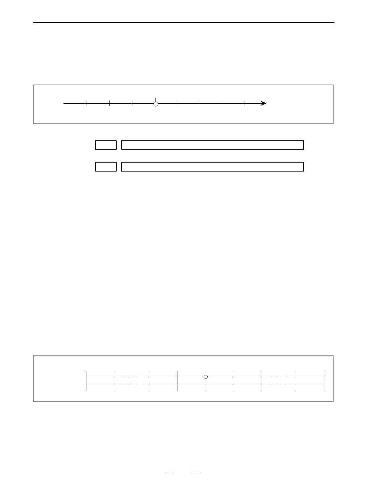
4. DESCRIPTION OF P ARAMETERS
B–62550EN/01
Setting the pitch error
compensation origin
1000 Pitch error compensation origin for the X–axis
to
3000 Pitch error compensation origin for the 3rd axis
[Data range] 0 to 128
[Description] These parameters are used to set the number of the pitch error
Up to 128 pitch error compensation points can be set. Among them,
specify the pitch error compensation point that corresponds to the
reference position, as the pitch error compensation origin. In the
following example, the pitch error compensation number corresponding
to the reference position is set to 33:
34 35 36 3733323130
Reference position
Compensation point
compensation origin for each axis.
Setting the pitch error
compensation
Machine
coordinate (mm)
Compensation
point number
–400 –350 –100 –50 0 50 100 750 800
33 39 40 41 42 56
Set the pitch error compensation for each compensation interval. The
pitch error compensation can be set within a range of 0 to "7. The actual
compensation values are obtained by multiplying the set values by a
magnification specified with a parameter.
Example:
Machine stroke : –400 mm to +800 mm
Pitch error compensation origin : 40
Pitch error compensation interval : 50 mm
Farthest compensation number in the positive direction =
(compensation origin number) +
(positive stroke/compensation interval) = 40 + 800/50= 56
Farthest compensation number in the negative direction =
(compensation origin number) –
(negative stroke/compensation interval) + 1 = 40 – 400/50 + 1 = 33
84
Page 88
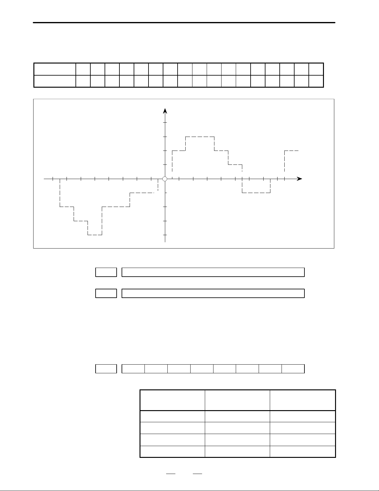
B–62550EN/01
4. DESCRIPTION OF P ARAMETERS
The compensation corresponding to each compensation point number is
output at the midpoint of the corresponding interval. The following is an
example:
Number 33 34 35 36 37 38 39 40 41 42 43 44 45 46 47 48 49
Compensation +2 +1 +1 –2 0 –1 0 –1 +2 +1 0 –1 –1 –2 0 +1 +2
Pitch error compensation (absolute value)
+4
+3
+2
–400 –300 –200 –100
001 Pitch error compensation value of No.0 of –th axis
to
128 Pitch error compensation value of No.127 of –th axis
[Data unit] No.0035#7 ACMR=0 Output unit Command multiplication (CMR)
[Data range] 0 to "7 (Detection unit Compensation magnification)
[Description] Set the pitch error compensation value of No.0 to 127 of –th axis
+1
4039383736353433 4847
0
–1
–2
–3
–4
100 200 300 400 (mm)
No.0035#7 ACMR=1 Detection unit
464544434241 49
Compensation
point number
Machine
coordinate
POWER OFF
0011
#7
#6 #5 #4 #3 #2 #1
PML2#0PML1
PML1, PML2 Set the magnification of pitch error compensation as below table.
#1
PML2
0 0 1
0 1 2
1 0 4
1 1 8
85
#0
PML1
Magnification
Page 89

4. DESCRIPTION OF P ARAMETERS
B–62550EN/01
Setting pitch error
compensation for a
rotation axis
Machine coordinate
Compensation point number
For a rotation axis, pitch error compensation of rotation axis type is
performed, such that any compensation points in the negative direction
are ignored. The result obtained by adding one to the result of dividing
the angle corresponding to a single revolution (360000) by the pitch error
compensation interval is set as the number of compensation points for a
rotation axis.
Reference position
0° 360°
012
n: Result obtained by dividing the angle corresponding to a single
revolution (360000) by the pitch error compensation interval
n–1 n
(+)(–)
Set 0 as the pitch error compensation origin. Set an identical value for the
pitch error compensation for both compensation points 0 and n.
Example:
When the pitch error compensation interval is set to 6°.
Parameter Set value
Pitch error compensation origin 0
Pitch error compensation interval 6000
In this case, set compensation values as follows:
( indicates the axis number.)
Parameter
(pitch error
compensation value)
001 Compensation value between –6° and 0°
(Compensation value between 354° and 360°)
002 Compensation value between 0° and 6°
003 Compensation value between 6° and 12°
L L
060 Compensation value between 348° and 354°
061 Compensation value between 354° and 360°
(Compensation value between –6° and 0°)
Set value of parameter
NOTE
1 Set a compensation interval such that 360000 can be
divided exactly by that value, without a remainder.
Otherwise, compensation will not be performed normally.
2 The sum of the compensation values for a single revolution
must be 0.
86
Page 90

B–62550EN/01
4. DESCRIPTION OF P ARAMETERS
1000 Zero point of pitch error compensation of X axis
2000 Zero point of pitch error compensation of Z axis
3000 Zero point of pitch error compensation of third axis
[Data unit] Number
[Data range] 0 to 127
[Description] Set number of zero point of pitch error compensation for each axis.
1001 Pitch error compensation value of No.0 of X axis
to
1128 Pitch error compensation value of No.127 of X axis
2001 Pitch error compensation value of No.0 of Z axis
to
2128 Pitch error compensation value of No.127 of Z axis
3001 Pitch error compensation value of No.0 of 3rd axis
to
3128 Pitch error compensation value of No.127 of 3rd axis
[Data unit] No.0035#7 ACMR=0 Output unit Command multiplication (CMR)
No.0035#7 ACMR=1 Detection unit
[Data range] 0 to "7
[Description] Set the pitch error compensation value of No.0 to 127 for each axis.
87
Page 91

4. DESCRIPTION OF P ARAMETERS
Parameters related to serial interface spindle
Sub–spindle parameters when the spindle switching function is provided
B–62550EN/01
The following parameters are not described in detail. The standard
settings listed in the tables need be modified for some machine systems.
First
spindle
6140
6141
6142
6143
6144
6145
6146
6147
6148
6149
6150
6151
6152
6153
6154
6155
6156
6157
6158
6159
6160
6161
6162
6163
6164
6165
6166
6167
6168
6169
Second
spindle
6320
6321
6322
6323
6324
6325
6326
6327
6328
6329
6330
6331
6332
6333
6334
6335
6336
6337
6338
6339
6340
6341
6342
6343
6344
6345
6346
6347
6348
6349
Description Standard setting
Bit parameter
Bit parameter
Bit parameter
Bit parameter
Bit parameter
Bit parameter
Bit parameter
Bit parameter
Bit parameter
Bit parameter
Bit parameter
Bit parameter
Bit parameter
Bit parameter
Bit parameter
Bit parameter
Bit parameter
Bit parameter
Bit parameter
Bit parameter
Maximum motor speed
Speed arrival detection level
Speed detection level
Speed zero detection level
Torque limit value
Load detection level 1
Output limit pattern
Output limit value
Position coder method orientation stop position
00000000
00000001
00000000
00000000
00000000
00000000
00000000
00000000
00000000
00000000
00000000
Model–dependent
Model–dependent
Model–dependent
00000000
00000000
00000000
00000000
00000000
00000000
Model–dependent
150
30
75
50
83
0
100
0
0
6170
6171
6172
6173
6174
6175
6176
6177
6178
6179
6350
6351
6352
6353
6354
6355
6356
6357
6358
6359
Normal velocity loop proportional gain (HIGH)
Normal velocity loop proportional gain (LOW)
Velocity loop proportional gain during orientation (HIGH)
Velocity loop proportional gain during orientation (LOW)
Velocity loop proportional gain in servo mode (HIGH)
Velocity loop proportional gain in servo mode (LOW)
Normal velocity loop integral gain
Velocity loop integral gain during orientation
Velocity loop integral gain in servo mode
88
10
10
10
10
10
10
10
10
10
0
Page 92

B–62550EN/01
4. DESCRIPTION OF P ARAMETERS
Sub–spindle parameters when the spindle switching function is provided
First
spindle
6180
6181
6182
6183
6184
6185
6186
6187
6188
6189
6190
6191
6192
6193
6194
6195
6196
6197
6198
6199
6200
6201
6202
6203
6204
6205
6206
6207
6208
6209
spindle
6360
6361
6362
6363
6364
6365
6366
6367
6368
6369
6370
6371
6372
6373
6374
6375
6376
6377
6378
6379
6380
6381
6382
6383
6384
6385
6386
6387
6388
6389
Gear ratio (HIGH)
Gear ratio (LOW)
Position gain during orientation (HIGH)
Position gain during orientation (LOW)
Position gain change ratio when orientation is completed
Position gain in servo mode (HIGH)
Position gain in servo mode (LOW)
Grid shift amount in servo mode
Orientation completion signal detection level
Motor velocity limit value during orientation
Orientation stop position shift amount
MS signal constant
MS signal gain adjustment
Regenerative power limit
Delay time prior motor power shut–off
Acceleration/deceleration time setting
Motor voltage during normal rotation
Motor voltage during orientation
Motor voltage in servo mode
Position gain change ratio when returning to the origin in the servo mode
Feed forward factor
Velocity loop feed forward factor
Standard settingDescriptionSecond
100
100
1000
1000
100
1000
1000
0
0
0
10
33
0
–
0
Model–dependent
20
10
0
0
Model–dependent
Model–dependent
Model–dependent
100
0
0
0
0
0
0
6210
6211
6212
6213
6214
6215
6216
6217
6218
6219
6220
6221
6222
6223
6224
6225
6226
6227
6228
6229
6390
6391
6392
6393
6394
6395
6396
6397
6398
6399
6400
6401
6402
6403
6404
6405
6406
6407
6408
6409
Base velocity of the motor output specification
Limit value for the motor output specification
Base speed
Magnetic flux weakening start velocity
Current loop proportional gain during normal operation
Current loop integral gain during normal operation
Zero point of current loop integral gain
Current loop proportional gain velocity factor
Current conversion constant
Secondary current factor for exciting current
0
0
0
0
0
0
0
0
0
0
Model–dependent
Model–dependent
Model–dependent
Model–dependent
Model–dependent
Model–dependent
Model–dependent
Model–dependent
Model–dependent
Model–dependent
89
Page 93

4. DESCRIPTION OF P ARAMETERS
Sub–spindle parameters when the spindle switching function is provided
B–62550EN/01
First
spindle
6230
6231
6232
6233
6234
6235
6236
6237
6238
6239
6240
6241
6242
6243
6244
6245
6246
6247
spindle
6410
6411
6412
6413
6414
6415
6416
6417
6418
6419
6420
6421
6422
6423
6424
6425
6426
6427
Current expectation constant
Slip constant
High–speed rotation slip compensation constant
Compensation constant of voltage applied to motor in the dead zone
Electromotive force compensation constant
Electromotive force phase compensation constant
Electromotive force compensation velocity factor
Time constant for changing the torque
Load meter displayed value for maximum output
Maximum output zero point
Secondary current factor during rigid tapping
Constant for compensating for the phase of the electromotive force at
deceleration
Time constant of the speed detection filter
Time constant of voltage filter for electromotive force compensation
Standard settingDescriptionSecond
Model–dependent
Model–dependent
Model–dependent
Model–dependent
Model–dependent
Model–dependent
Model–dependent
5
Model–dependent
Model–dependent
Model–dependent
Model–dependent
0
0
0
0
0
0
90
Page 94

B–62550EN/01
4. DESCRIPTION OF P ARAMETERS
Sub–spindle parameters for low–speed operation when the spindle switching function is provided
and the output switching function is provided for the sub–spindle
First
spindle
6248
6249
6250
6251
6252
6253
6254
6255
6256
6257
6258
6259
6260
6261
6262
6263
6264
6265
6266
6267
6268
6269
Second
spindle
6428
6429
6430
6431
6432
6433
6434
6435
6436
6437
6438
6439
6440
6441
6442
6443
6444
6445
6446
6447
6448
6449
Description Standard setting
Motor voltage during normal rotation
Motor voltage in the servo mode
Base speed of the motor output specifications
Limit value for the motor output specifications
Base speed
Magnetic flux weakening start velocity
Current loop proportional gain during normal operation
Current loop integral gain during normal operation
Zero point of the current loop integral gain
Velocity factor of the current loop proportional gain
Current conversion constant
Secondary current factor for activating current
Current expectation constant
Slip constant
High–speed rotation slip compensation constant
Compensation constant for voltage applied to motor in the dead zone
Electromotive force compensation constant
Electromotive force phase compensation constant
Velocity factor of the electromotive force compensation
Time constant for changing the torque
Maximum output zero point
Secondary current factor during rigid tapping
Model–dependent
Model–dependent
Model–dependent
Model–dependent
Model–dependent
Model–dependent
Model–dependent
Model–dependent
Model–dependent
Model–dependent
Model–dependent
Model–dependent
Model–dependent
Model–dependent
Model–dependent
Model–dependent
Model–dependent
Model–dependent
Model–dependent
Model–dependent
Model–dependent
Model–dependent
6270
6271
6272
6273
6274
6275
6276
6277
6278
6279
6280
6281
6282
6283
6284
6285
6286
6287
6288
6289
6290
6291
6292
6293
6294
6295
6296
6297
6298
6299
6450
6451
6452
6453
6454
6455
6456
6457
6458
6459
6460
6461
6462
6463
6464
6465
6466
6467
6468
6469
6470
6471
6472
6473
6474
6475
6476
6477
6478
6479
Voltage compensation factor during deceleration
Regenerative power limit
Time constant of voltage filter for electromotive force compensation
Motor model code
Model–dependent
Model–dependent
0
Model–dependent
0
0
0
0
0
0
0
0
0
0
0
0
0
0
0
0
0
0
0
0
0
0
0
0
0
0
91
Page 95

4. DESCRIPTION OF P ARAMETERS
B–62550EN/01
Sub–spindle parameters for low–speed operation when the spindle switching function is provided
and the output switching function is provided for the sub–spindle
First
spindle
6300
6301
6302
6303
6304
6305
6306
6307
6308
6309
6310
6311
6312
6313
6314
6315
spindle
6480
6481
6482
6483
6484
6485
6486
6487
6488
6489
6490
6491
6492
6493
6494
6495
Overload current alarm detection level (for low speed characteristic)
Overload current alarm detection time constant
Overload current alarm detection level (for high speed characteristic)
Compensation for current detection offset
Standard settingDescriptionSecond
0
0
0
0
0
0
0
0
0
0
0
0
Model–dependent
Model–dependent
Model–dependent
0
92
Page 96

B–62550EN/01
4. DESCRIPTION OF P ARAMETERS
Parameters for standard motors (parameters for high–speed operation
when the output switching function is provided)
First
spindle
6500
6501
6502
6503
6504
6505
6506
6507
6508
6509
6510
651 1
6512
6513
6514
6515
6516
6517
6518
6519
6520
6521
6522
6523
6524
6525
6526
6527
6528
6529
Second
spindle
6640
6641
6642
6643
6644
6645
6646
6647
6648
6649
6650
6651
6652
6653
6654
6655
6656
6657
6658
6659
6660
6661
6662
6663
6664
6665
6666
6667
6668
6669
Description Standard setting
Bit parameter
Bit parameter
Bit parameter
Bit parameter
Bit parameter
Bit parameter
Bit parameter
Bit parameter
Bit parameter
Bit parameter
Bit parameter
Bit parameter
Bit parameter
Bit parameter
Bit parameter
Bit parameter
Bit parameter
Bit parameter
Bit parameter
Bit parameter
Maximum motor speed
Maximum speed when the Cs axis is controlled
Speed arrival detection level
Speed detection level
Speed zero detection level
Torque limit value
Load detection level 1
Load detection level 2
Output limit pattern
Output limit value
00000000
00000001
00000000
00000000
00000000
00000000
00000000
00000000
00000000
00000000
00000000
Model–dependent
Model–dependent
Model–dependent
00000000
00000000
00000000
00000000
00000000
00000000
Model–dependent
100
150
30
75
50
83
95
0
100
6530
6531
6532
6533
6534
6535
6536
6537
6538
6539
6540
6541
6542
6543
6544
6545
6546
6547
6548
6549
6670
6671
6672
6673
6674
6675
6676
6677
6678
6679
6680
6681
6682
6683
6684
6685
6686
6687
6688
6689
Soft start/stop time
Position coder method orientation stop position
Acc./dec. time constant when the spindle synchronization is controlled
Arrival level for the spindle synchronization speed
Shift amount when the spindle phase synchronization is controlled
Spindle phase synchronization compensation data
Feed forward factor
Velocity loop feed forward factor
Normal velocity loop proportional gain (HIGH)
Normal velocity loop proportional gain (LOW)
Velocity loop proportional gain during orientation (HIGH)
Velocity loop proportional gain during orientation (LOW)
Velocity loop proportional gain in servo mode (HIGH)
Velocity loop proportional gain in servo mode (LOW)
Velocity loop proportional gain when the Cs axis is controlled (HIGH)
Velocity loop proportional gain when the Cs axis is controlled (LOW)
Normal velocity loop integral gain (HIGH)
Normal velocity loop integral gain (LOW)
93
0
0
0
100
0
10
0
0
0
0
10
10
10
10
10
10
30
30
10
10
Page 97

4. DESCRIPTION OF P ARAMETERS
Parameters for standard motors (parameters for high–speed operation
when the output switching function is provided)
B–62550EN/01
First
spindle
6550
6551
6552
6553
6554
6555
6556
6557
6558
6559
6560
6561
6562
6563
6564
6565
6566
6567
6568
6569
6570
6571
6572
6573
6574
6575
6576
6577
6578
6579
spindle
6690
6691
6692
6693
6694
6695
6696
6697
6698
6699
6700
6701
6702
6703
6704
6705
6706
6707
6708
6709
6710
6711
6712
6713
6714
6715
6716
6717
6718
6719
Velocity loop integral gain during orientation (HIGH)
Velocity loop integral gain during orientation (LOW)
Velocity loop integral gain in servo mode (HIGH)
Velocity loop integral gain in servo mode (LOW)
Velocity loop integral gain when the Cs axis is controlled (HIGH)
Velocity loop integral gain when the Cs axis is controlled (LOW)
Gear ratio (HIGH)
Gear ratio (MEDIUM HIGH)
Gear ratio (MEDIUM LOW)
Gear ratio (LOW)
Position gain during orientation (HIGH)
Position gain during orientation (MEDIUM HIGH)
Position gain during orientation (MEDIUM LOW)
Position gain during orientation (LOW)
Position gain change ratio when orientation is completed
Position gain in servo mode (HIGH)
Position gain in servo mode (MEDIUM HIGH)
Position gain in servo mode (MEDIUM LOW)
Position gain in servo mode (LOW)
Position gain when the Cs axis is controlled (HIGH)
Position gain when the Cs axis is controlled (MEDIUM HIGH)
Position gain when the Cs axis is controlled (MEDIUM LOW)
Position gain when the Cs axis is controlled (LOW)
Grid shift amount in servo mode
Reference position return speed in Cs contouring control mode or servo
mode
Orientation completion signal detection level
Motor velocity limit value during orientation
Orientation stop position shift amount
MS signal constant
MS signal gain adjustment
Standard settingDescriptionSecond
10
10
10
10
50
50
100
100
100
100
1000
1000
1000
1000
100
1000
1000
1000
1000
3000
3000
3000
3000
0
0
10
33
0
–
0
6580
6581
6582
6583
6584
6585
6586
6587
6588
6589
6590
6591
6592
6593
6594
6595
6596
6597
6598
6599
6720
6721
6722
6723
6724
6725
6726
6727
6728
6729
6730
6731
6732
6733
6734
6735
6736
6737
6738
6739
Regenerative power limit
Delay time prior motor power shut–off
Acceleration/deceleration time setting
Motor voltage during normal rotation
Motor voltage during orientation
Motor voltage in servo mode/synchronous control
Motor voltage when the Cs axis is controlled
Over–speed detection level
Excessive velocity deviation detection level when the motor is constrained
Excessive velocity deviation detection level when the motor is rotated
Overload detection level
Position gain change ratio when returning to the origin in the servo mode
Position gain change ratio when returning to the origin in Cs axis control
Acceleration presumed constant
Disturbance torque compensation constant
Speed meter output voltage adjustment value
Load meter output voltage adjustment value
Spindle velocity feedback gain
Maximum speed at which position coder signal can be detected
Delay time for energizing the motor
94
Model–dependent
20
10
Model–dependent
Model–dependent
Model–dependent
Model–dependent
115
75
200
90
100
100
0
0
0
0
0
0
0
Page 98

B–62550EN/01
4. DESCRIPTION OF P ARAMETERS
Parameters for standard motors (parameters for high–speed operation
when the output switching function is provided)
First
spindle
6600
6601
6602
6603
6604
6605
6606
6607
6608
6609
6610
6611
6612
6613
6614
6615
6616
6617
6618
6619
6620
6621
6622
6623
6624
6625
6626
6627
6628
6629
spindle
6740
6741
6742
6743
6744
6745
6746
6747
6748
6749
6750
6751
6752
6753
6754
6755
6756
6757
6758
6759
6760
6761
6762
6763
6764
6765
6766
6767
6768
6769
Base velocity of the motor output specification
Limit value for the motor output specification
Base speed
Magnetic flux weakening start velocity
Current loop proportional gain during normal operation
Current loop proportional gain at the Cs contour control
Current loop integral gain during normal operation
Current loop integral gain at the Cs contour control
Zero point of current loop integral gain
Current loop proportional gain velocity factor
Current conversion constant
Secondary current factor for exciting current
Current expectation constant
Slip constant
High–speed rotation slip compensation constant
Compensation constant of voltage applied to motor in the dead zone
Electromotive force compensation constant
Electromotive force phase compensation constant
Electromotive force compensation velocity factor
Time constant of voltage filter for electromotive force compensation
Dead zone compensation data
Time constant for changing the torque
Velocity filter
Overload detection time setting
Timer during automatic running
Velocity command during automatic running
Load meter displayed value for maximum output
Maximum output zero point
Secondary current factor during rigid tapping
Standard settingDescriptionSecond
Model–dependent
Model–dependent
Model–dependent
Model–dependent
Model–dependent
Model–dependent
Model–dependent
Model–dependent
Model–dependent
Model–dependent
Model–dependent
Model–dependent
Model–dependent
Model–dependent
Model–dependent
Model–dependent
Model–dependent
Model–dependent
Model–dependent
0
Model–dependent
5
0
30
0
100
1000
Model–dependent
Model–dependent
Model–dependent
6630
6631
6632
6633
6634
6635
6770
6771
6772
6773
6774
6775
Constant for compensating for the phase of the electromotive force at
deceleration
Time constant of the speed detection filter at the Cs contour control
Conversion constant of the phase–V current
Motor model code
Grid shift amount when the C axis is controlled
Model–dependent
0
0
Model–dependent
0
0
95
Page 99

4. DESCRIPTION OF P ARAMETERS
Parameters for low–speed operation when the output switching function is provided
B–62550EN/01
First
spindle
6900
6901
6902
6903
6904
6905
6906
6907
6908
6909
6910
6911
6912
6913
6914
6915
6916
6917
6918
6919
6920
6921
6922
6923
6924
6925
6926
6927
6928
6929
Second
spindle
6940
6941
6942
6943
6944
6945
6946
6947
6948
6949
6950
6951
6952
6953
6954
6955
6956
6957
6958
6959
6960
6961
6962
6963
6964
6965
6966
6967
6968
6969
Description Standard setting
Motor voltage during normal rotation
Motor voltage in the servo mode
Base speed of the motor output specifications
Limit value for the motor output specifications
Base speed
Magnetic flux weakening start velocity
Current loop proportional gain during normal operation
Current loop integral gain during normal operation
Zero point of current loop integral gain
Velocity factor of current loop proportional gain
Current conversion constant
Secondary current factor for excitation current
Current expectation constant
Slip constant
Compensation constant for high–speed rotation slip
Compensation constant for voltage applied to motor in the dead zone
Electromotive force compensation constant
Phase compensation constant for electromotive force
Compensation velocity factor for electromotive force
Time constant for changing the torque
Maximum output zero point
Secondary current factor in rigid tapping
Hysteresis of the speed detection signal (SDT) output
Constant for compensating for the phase of the electromotive force at
deceleration
Velocity loop integral gain when the Cs axis is controlled (HIGH)
Velocity loop integral gain when the Cs axis is controlled (LOW)
Conversion constant of the phase–V current
Time constant of voltage filter for eletromotive force compensation
Model–dependent
Model–dependent
Model–dependent
Model–dependent
Model–dependent
Model–dependent
Model–dependent
Model–dependent
Model–dependent
Model–dependent
Model–dependent
Model–dependent
Model–dependent
Model–dependent
Model–dependent
Model–dependent
Model–dependent
Model–dependent
Model–dependent
0
0
Model–dependent
Model–dependent
Model–dependent
0
Model–dependent
0
0
0
0
6930
6931
6932
6933
6934
6935
6936
6937
6938
6939
6970
6971
6972
6973
6974
6975
6976
6977
6978
6979
Regenerative power limit
Overload current alarm detection level (for low speed characteristic)
Overload current alarm detection time constant
Overload current alarm detection level (for high speed characteristic)
Delay timer at ON of electromagnetic contactor in unit
Model–dependent
0
Model–dependent
Model–dependent
Model–dependent
–
0
0
0
0
96
Page 100

B–62550EN/01
No
4. DESCRIPTION OF P ARAMETERS
Parameters related to servo
The following parameters are not explained in this manual:
N
.
.
800 POWER OFF DGPRM HRPLC
801 POWER OFF AMR7 AMR6 AMR5 AMR4 AMR3 AMR2 AMR1 AMR0
802 POWER OFF 0 1
803 POWER OFF VOFST OVSCMP BLENBL IPSPRS PIENBL OBENBL TGALRM 1
804 POWER OFF DLY1 DLY0 TRW1 TRW0 TIB0 TIA0
805 POWER OFF BRKCTL FEEDFD
806 DCBEMF
807
808
809 BLSTP BLCUT ADBLSH
810 BLTEN SPBIT
811 BLSTP PGEXPD
812 VCMD2 VCMD1 MSFEN
813
814
#7 #6 #5 #4 #3 #2 #1 #1
Contents
MODEL
ACCFB
PKVER FCBLCM
815
816
817
818
819
820 POWER OFF Motor type
821 Load inertia ratio (LDINT)
822 POWER OFF Direction of motor rotation (DIRCTL)
823 POWER OFF Number of velocity detection feedback pulses (PULCO)
824 POWER OFF Number of position detection feedback pulses (PPLS)
825
826
827
828
829
830
831
97
 Loading...