


QS4 Fire Alarm Control Panel
Technical Reference Manual
P/N 3100186 • Rev 2.0 • 12JUL01
Technical Manuals Online! - http://www.tech-man.com

Compliance Statement
The QS4, hereinafter referred to as the FACP or control panel, when
properly installed, operates as a Local Protected Premises Fire Alarm
System in accordance with the following standards:
• NFPA Standard 72, 1999 Edition
• Underwriters Laboratories Standard 864, 7th Edition
• Underwriters Laboratories of Canada Standard ULC S527
In addition, Auxiliary Fire Alarm System operation requires a Reverse
Polarity Module (RPM). Central Station Fire Alarm System operation
requires a Dialer card (DLD).
Installation in accordance with this manual, applicable codes, and the
instructions of the authority having jurisdiction is mandatory.
Limitation of Liability
Fire Alarm System
Limitations
FCC Compliance Statement
Edwards Systems Technology (EST) shall not under any circumstances
be liable for any incidental or consequential damages arising from loss
of property or other damages or losses owing to the failure of EST
products beyond the cost of repair or replacement of any defective
products. EST reserves the right to make product improvements and
changes to product specifications at any time.
While every precaution was taken during the preparation of this
document to ensure its accuracy, EST assumes no responsibility for
errors or omissions.
Automatic fire alarm systems can not guarantee against property
damage, loss of property, or loss of life. An automatic fire alarm system's
ability to provide early warning of a developing fire may be limited for a
variety of reasons, but mainly due to improper installation or
maintenance.
The best way to minimize system failures is to perform regularly
scheduled preventive maintenance in accordance with national and local
fire codes. All system components and wiring should be tested and
maintained by trained fire alarm system professionals.
This equipment can generate and radiate radio frequency energy. If this
equipment is not installed in accordance with this manual, it may cause
interference to radio communications. This equipment has been tested
and found to comply within the limits for Class A computing devices
pursuant to Subpart B of Part 15 of the FCC Rules. These rules are
designed to provide reasonable protection against such interference
when this equipment is operated in a commercial environment.
Operation of this equipment is likely to cause interference, in which case
the user at his own expense, will be required to take whatever measures
may be required to correct the interference.
Copyright © 2001. All rights reserved.
Technical Manuals Online! - http://www.tech-man.com

About this manual • iii
Related documentation • iv
Document history • vi
Chapter 1 Product description • 1.1
System overview • 1.2
Component descriptions • 1.3
Circuit descriptions • 1.5
Controls and indicators • 1.9
Controls and indicators behind the flip-down cover • 1.10
Controls and indicators on the zone annunciator card • 1.11
Interpretation of screen displays • 1.12
Chapter 2 Installation • 2.1
Installation do's and don'ts • 2.2
Installation checklist • 2.3
Two ways to install the cabinet: Surface or semi-flush mount • 2.4
How to assemble the panel • 2.6
Wiring mains ac and earth ground • 2.7
System jumper settings • 2.8
System addressing • 2.10
Terminal definitions • 2.14
Connecting a PT–1S printer • 2.22
Installing standby batteries • 2.23
Content
Chapter 3 Operating instructions • 3.1
Instructions for the Level 1 operator (public mode access) • 3.2
Instructions for the Level 2 operator (emergency mode access) • 3.5
Instructions for the Level 3 operator (maintenance mode access) • 3.7
Instructions for the Level 4 operator (service mode access) • 3.10
QuickReference list • 3.11
Chapter 4 Programming instructions • 4.1
Overview • 4.2
QuickStart setup instructions • 4.4
Customizing the system configuration • 4.13
Setting up an Output Group • 4.21
Setting up a Zone • 4.26
Chapter 5 Standard applications • 5.1
Notification appliance circuits • 5.2
Initiating device circuits • 5.5
Coded alarm signaling • 5.8
Remote station protective signaling system • 5.10
Auxiliary protective signaling • 5.12
Chapter 6 Maintenance instructions • 6.1
Pseudo point definitions • 6.2
Maintenance tasks • 6.6
QS4 Technical Reference Manual i
Technical Manuals Online! - http://www.tech-man.com

Content
Appendix A System calculations • A.1
Notification appliance circuit maximum wire length calculation • A.2
Signature loop maximum wire length calculations • A.3
Battery calculation worksheet • A.8
Appendix B Barcode library • B.1
Appendix C SIGA-REL programming • C.1
Application block diagram • C.2
Programming instructions • C.3
ii QS4 Technical Reference Manual
Technical Manuals Online! - http://www.tech-man.com

Content
About this manual
Organization
This manual provides information on how to properly install, wire, and
maintain the FACP and related components, and is organized as
follows:
Chapter 1 provides a detailed description of the fire alarm control panel
and its operation.
Chapter 2 provides instructions for installing the fire alarm control
panel.
Chapter 3 provides instructions for operating the control panel.
Chapter 4 provides instructions for programming the fire alarm system
from the front panel.
Chapter 5 provides simplified wiring schematics for standard
applications.
Chapter 6 provides instructions for maintaining the system.
Appendix A provides worksheets for calculating maximum wire lengths
for notification and Signature circuits, and for sizing standby batteries.
Appendix B provides a set of bar codes that you can use to enter text
for location messages.
Appendix C provides information on how to program the SIGA–REL
using the QS–CU (QuickStart Configuration Utility).
Safety information
Important safety admonishments are used throughout this manual to
warn of possible hazards to persons or equipment.
WARNING: Warnings are used to indicate the presence of a hazard
which will or may cause personal injury or death, or loss of service if
safety instructions are not followed or if the hazard is not avoided.
Caution: Cautions are used to indicate the presence of a hazard which
will or may cause damage to the equipment if safety instructions are not
followed or if the hazard is not avoided.
QS4 Technical Reference Manual iii
Technical Manuals Online! - http://www.tech-man.com

Content
Related documentation
National Fire Protection Association
1 Batterymarch Park
P.O. Box 9101
Quincy, MA 02269-9101
Underwriters Laboratories, Inc.
333 Pfingsten Road
Northbrook, IL 60062-2096
NFPA 70 National Electric Code
NFPA 72 National Fire Alarm Code
NFPA 11 Low-Expansion Foam Systems
NFPA 11A Medium- and High-Expansion Foam Systems
NFPA 12 Carbon Dioxide Extinguishing Systems
NFPA 13 Sprinkler Systems
NFPA 15 Water Spray Fixed Systems for Fire Protection
NFPA 16 Deluge Foam-Water Sprinkler and Foam-Water Spray
Systems
NFPA 17Dry Chemical Extinguishing Systems
UL 38 Manually Actuated Signaling Boxes
UL 217 Smoke Detectors, Single & Multiple Station
UL 228 Door Closers/Holders for Fire Protective Signaling
Systems
UL 268 Smoke Detectors for Fire Protective Signaling Systems
UL 268A Smoke Detectors for Duct Applications
UL 346 Waterflow Indicators for Fire Protective Signaling
Systems
Underwriters Laboratories of
Canada
7 Crouse Road
Scarborough, ON
Canada M1R 3A9
UL 464 Audible Signaling Appliances
UL 521 Heat Detectors for Fire Protective Signaling Systems
UL 864 Standard for Control Units for Fire Protective Signaling
Systems
UL 1481 Power Supplies for Fire Protective Signaling Systems
UL 1638 Visual Signaling Appliances
UL 1971 Visual Signaling Appliances
Canadian Electrical Code Part 1
ULC S527 Standard for Control Units for Fire Alarm Systems
ULC S524 Standard for the Installation of Fire Alarm Systems
ULC S536 Standard for the Inspection and Testing of Fire
Alarm Systems
ULC S537 Standard for the Verification of Fire Alarm Systems
ULC ORD–C693–1994 Central Station Fire Protective Signaling
System and Services
iv QS4 Technical Reference Manual
Technical Manuals Online! - http://www.tech-man.com

Content
Edwards Systems Technology
6411 Parkland Drive
Sarasota, FL 34243
2–CTM City Tie Module Installation Sheet (P/N 270496)
CDR–3 Bell Coder Installation Sheet (P/N 3100023)
DLD Dual Inline Dialer Installation Sheet (P/N 3100187)
PS6 Power Supply Card Installation Sheet (P/N 3100201)
QSA–1(X), QSA–2(X) Remote Annunciator Cabinet Installation
Sheet (P/N 3100295)
QS–CPU(X) CPU/Display Unit Installation Sheet (P/N 3100276)
SL30, SL30–1 LED/Switch Card Installation Sheet (P/N
3100193)
SLIC Signature Intelligent Controller Card Installation Sheet
(P/N 3100192)
RS485 (NT–A) Card and QS–232 UART Module Installation
Sheet (P/N 3100191)
ZA8–2 Class A Zone Card Installation Sheet (P/N 3100189)
ZB16–4 Class B Zone Card Installation Sheet (P/N 3100188)
ZR8 Relay Card Installation Sheet (P/N 3100190)
SIGA–APS Auxiliary Power Supply Installation Sheet (P/N
387342)
Signature Series Intelligent Smoke and Heat Detectors
Applications Bulletin (P/N 270145)
Signature Series Component Installation Manual (P/N 270497)
EST Strobe Applications Guide (P/N 85000-0049)
QuickStart Online Help Utility (P/N 7350047)
QuickStart ULI and ULC Compatibility Lists (P/N 3100335)
Network Hardware Technical Reference (P/N 250100)
QS4 Technical Reference Manual v
Technical Manuals Online! - http://www.tech-man.com

Content
Document history
Date Revision Description of changes
24JUN01 1.0 Original release.
12JUL01 2.0 Corrections and additions on pp 2.12, 2.24, 3.9, 4.4, 4.8, 4.10, 4.19,
A.3.
vi QS4 Technical Reference Manual
Technical Manuals Online! - http://www.tech-man.com

Chapter 1
Product description
Summary
This chapter provides a detailed description of the fire alarm control
panel and its operation.
Content
System overview • 1.2
Component descriptions • 1.3
Circuit descriptions • 1.5
Controls and indicators • 1.9
Controls and indicators behind the flip-down cover • 1.10
Controls and indicators on the zone annunciator card • 1.11
Interpretation of screen displays • 1.12
QS4 Technical Reference Manual 1.1
Technical Manuals Online! - http://www.tech-man.com

Product description
System overview
System hardware capabilities
Hardware capabilities vary depending on cabinet
size and option card configuration, but generally:
• Up to four Class A or Class B Signature
signaling line circuits that support up to 250
single-address Signature devices each
• Up to 40 Class A or 48 Class B initiating device
circuits (IDC). Combination systems can not
exceed 40 IDC circuits total
• Up to 16 Class A or 20 Class B notification
appliance
• Up to two 30-zone displays
• Up to 96 dry-contact relay
• 4.5 amps of 24 Vdc power for external
notification appliances
• Battery charger capable of charging batteries
rated up to 40 Ah. Maximum battery size for
ULC applications is 30 Ah
• Up to eight, fully-supervised, mirrored or
customized remote annunciators
Minimum system requirements
A Local Protected Premises Fire Alarm System
requires only the FACP (CPU, PS6, and
enclosure) with at least one SLIC, ZB16–4, or
ZA8–2 card programmed with at least one audible
output circuit and one alarm input circuit.
In addition to the hardware requirements of a
Local system:
• Add a 2–CTM City Tie Module for an Auxiliary
Fire Alarm System
• Add a DLD Dual Line Dialer Card or RPM
Reverse Polarity Module for a Remote
Supervising Station Fire Alarm System
• Add a DLD Dual Line Dialer Card or RPM
Reverse Polarity Module for a Central Station
Fire Alarm System
• Add a SIGA–REL for Releasing Device Service
monitor events. In normal mode, the control panel
monitors the system for any events.
Off-normal operating mode description
The panel operates in off-normal mode any time
there is an event introduced into the system.
When this happens, the CPU:
• Changes the contact positions on the
appropriate common relays
• Activates all common alarm outputs (alarm
events only)
• Turns on the panel buzzer
• Executes the appropriate programmed output
response for the input that signaled the event
• Sends a record of the event to the appropriate
display queue and out the serial port
If there is no operator in attendance, the panel
displays the content of the highest priority display
queue containing a record.
If there is an operator in attendance, the panel
displays the content of the current display queue
regardless of any new events introduced into the
system.
Failsafe operating mode description
The panel operates in failsafe mode when the
CPU loses the ability to communicate with the PS6
and JP1 on the PS6 is in the ON position. When
this happens, the power supply:
• Closes the common trouble relay contacts
• Instructs the dialer to send the default trouble
message
• Monitors the system for any alarm events
If an alarm event occurs, the power supply:
• Changes the contact positions on the common
alarm relay
• Turns on all conventional common alarm
outputs. Signature common alarm outputs are
not affected.
Normal operating mode description
The panel operates in normal mode in the
absence of any alarm, supervisory, trouble, and
1.2 QS4 Technical Reference Manual
Technical Manuals Online! - http://www.tech-man.com
• Instructs the dialer to send the default alarm
message
Component descriptions
Product description
1 2 3
J5
6A
JP1 CONFIGURATION
PIN 1 & 2 = MODEM PWR
PIN 2 & 3 = RTS
5
6B
J6
J7
J8
JP1
J2
13
7 84
9
10
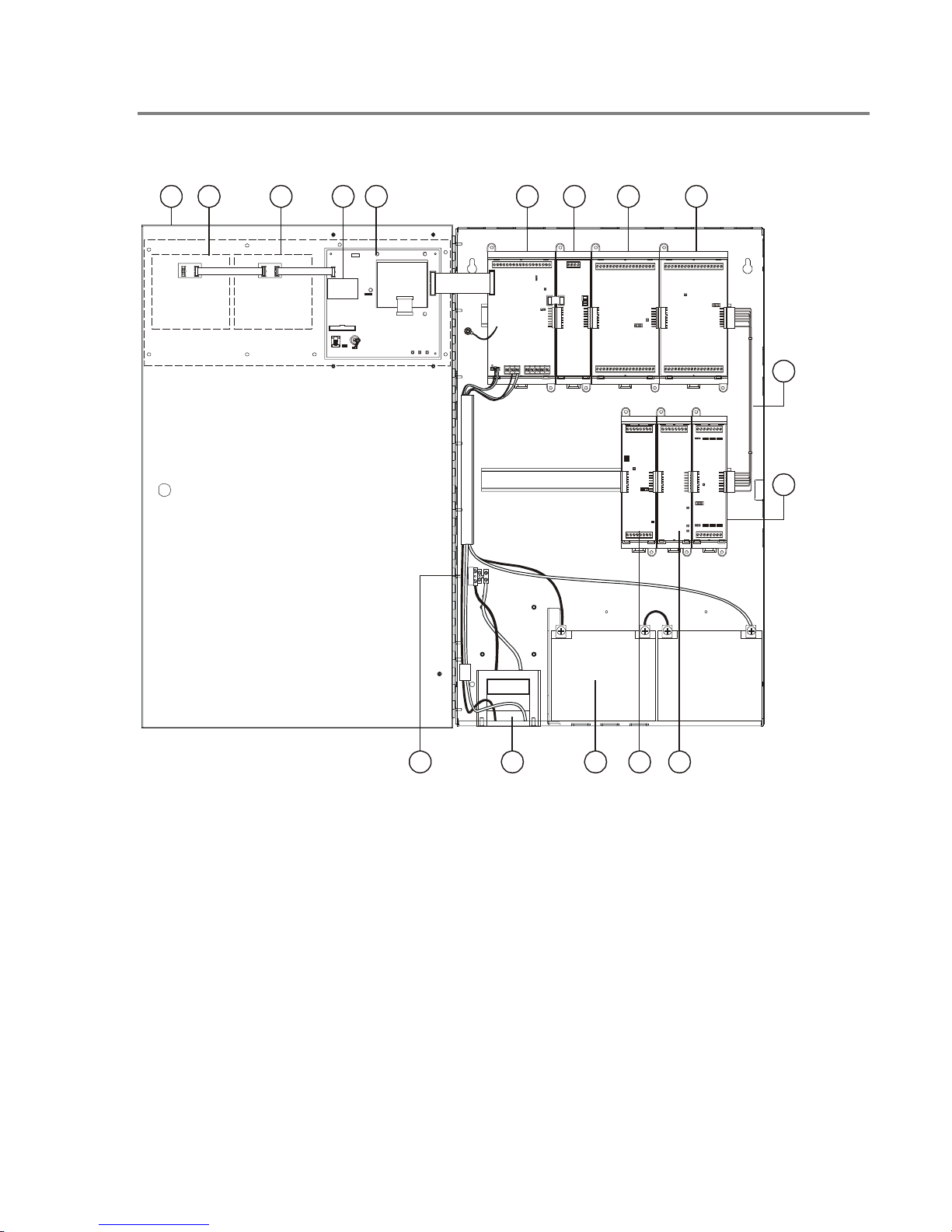
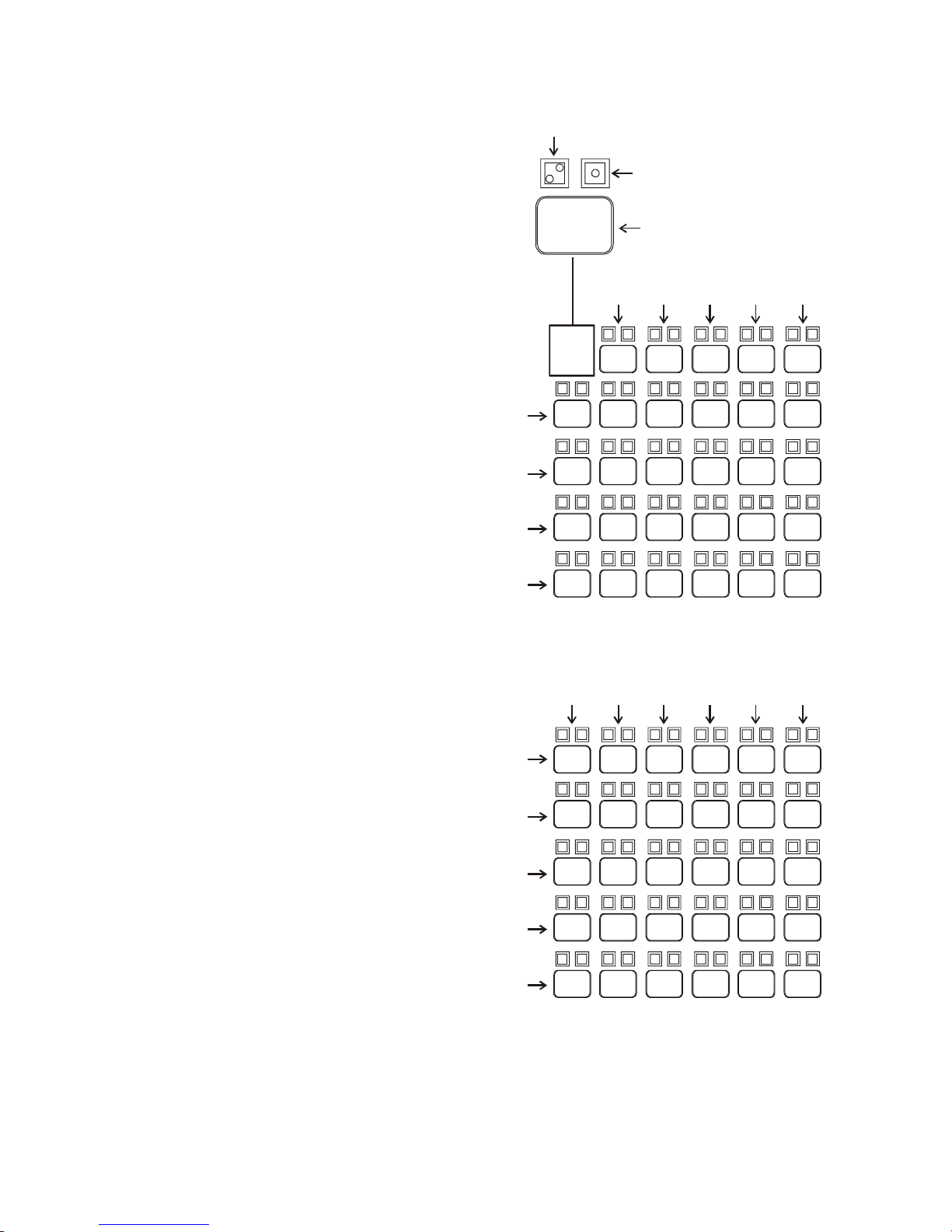
1. Cabinet enclosure: Houses the panel
electronics and standby batteries.
2. SL30–1 LED/Switch Card: Provides thirty
circuits for point or zone annunciation. Each
circuit has two LEDs for annunciating alarm,
supervisory, and trouble signals, and a button
numbered from 31 to 60.
3. SL30 LED/Switch Card: Same as SL30–1
except the buttons are numbered 1–30.
QS4 Technical Reference Manual 1.3
Technical Manuals Online! - http://www.tech-man.com
14 13 111215
4. CPU/Display: Provides operator access to
system messages, status information, and
programming menus, and executes system
responses based on the panel programming.
5. PS6 Power Supply Card: Provides primary dc
power to the panel electronics and external
circuits. The PS6 also provides common alarm,
supervisory and trouble relays for remote station
supervision.

Product description
6. RS485 (NT–A) Class A Card: The NT–A
comprises the RS485 card and QS–232 UART
module. Together these provide an additional
RS–232 channel to allow Class A communication
between the control panel and other remote
annunciator panels. Control panels require
installation of both cards while remote
annunciator panels only require installation of a
QS–232 card and only then if you want to
connect a printer or service computer.
7. ZA8–2 Class A Conventional Zone Card:
Provides six dedicated Class A initiating device
circuits (IDCs) for connecting two-wire smoke
detectors and dry-contact initiating devices. The
ZA8–2 also provides two circuits that you can
configure as IDCs or as 24 Vdc notification
appliance circuits (NACs).
8. ZB16–4 Class B Conventional Zone Card:
Provides twelve dedicated Class B initiating
device circuits (IDCs) for connecting two-wire
smoke detectors and dry-contact initiating
devices. The ZB16–4 also provides four circuits
that you can configure as IDCs or as Class B 24
Vdc notification appliance circuits (NACs).
10. ZR8 Relay Card: Provides eight dry-contact
relays. You can configure each relay for
normally-open or normally-closed operation.
11. DLD Dual Line Dialer Card: Provides two
telephone line connections for sending system
messages to a compatible Digital Alarm
Communicator Receiver.
12. SLIC Signature Loop Intelligent Controller
Card: Provides one Class A or Class B signaling
line circuit (loop) for connecting Signature series
detectors and modules. The SLIC also provides
two Class A or Class B notification appliance
circuits (NACs) for connecting polarized 24 Vdc
notification appliances (horns, strobes).
13. Standby batteries: Provides dc power to the
panel electronics in the absence of ac power.
14. Transformer: Changes the mains ac supply
voltage for the power supply card.
15. AC wiring block and fuse holder: Provides
connections for mains ac (primary power) and 5A
fuse.
9. QS–Cable12 Expansion Cable: Extends the
CPU data and power bus to circuit cards installed
on the lower DIN rail in the 12-option cabinet.
1.4 QS4 Technical Reference Manual
Technical Manuals Online! - http://www.tech-man.com

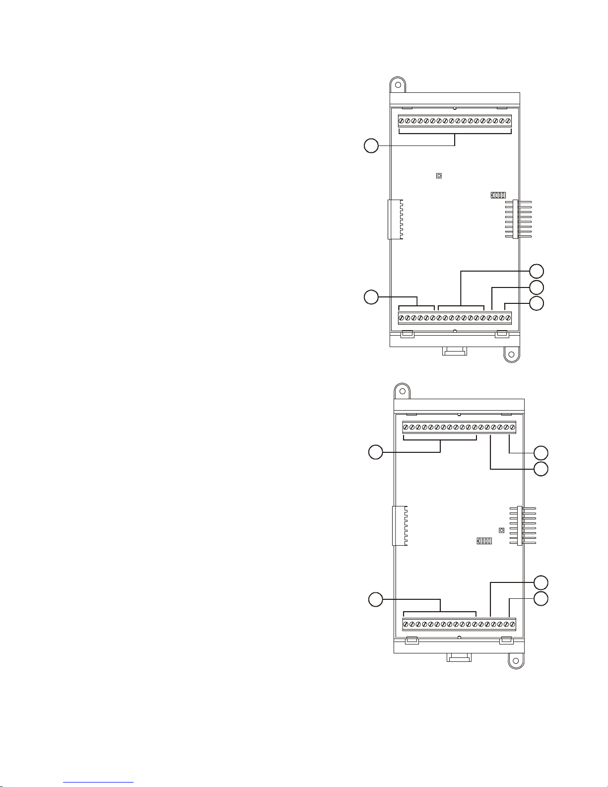
Circuit descriptions
PS6 Power Supply Card
1. Relay 1 (Common Alarm)
Style: Form C
Contact rating: 1 A @ 20.4 – 26.4 Vdc (0.6 PF)
Wire size: 18 to 12 AWG (0.75 to 2.5 mm²)
Nonsupervised and power-limited only when
connected to a power-limited source
2. Relay 2 (Common Supervisory)
Style: Normally-open
Contact rating: 1 A @ 20.4 – 26.4 Vdc (0.6 PF)
Wire size: 18 to 12 AWG (0.75 to 2.5 mm²)
Nonsupervised and power-limited only when
connected to a power-limited source
3. Relay 3 (Common Trouble)
Style: Normally-open, held closed
Contact rating: 1 A @ 20.4 – 26.4 Vdc (0.6 PF)
Wire size: 18 to 12 AWG (0.75 to 2.5 mm²)
Nonsupervised and power-limited only when
connected to a power-limited source
Product description
2
534
6
71
4. Relay 4 (Programmable)
Style: Normally-open
Contact rating: 1 A @ 20.4 – 26.4 Vdc (0.6 PF)
Wire size: 18 to 12 AWG (0.75 to 2.5 mm²)
Nonsupervised and power-limited only when
connected to a power-limited source
5. Smoke/Accessory Power
Output: Continuous or interruptible via jumper
selection
Voltage: 24 Vdc, regulated
Current: 250 mA
Wire size: 18 to 12 AWG (0.75 to 2.5 mm²)
Supervised and power-limited
6. RS485
Wire size: 18 to 12 AWG (0.75 to 2.5 mm²)
Wire type: Twisted pair, six twists per foot
minimum
Circuit capacitance: 0.4 µF
Circuit resistance: 100 Ω
Supervised and power-limited
7. RS232
Wire size: 18 to 12 AWG (0.75 to 2.5 mm²)
Nonsupervised and power-limited
Wire length: 20 ft maximimum
9
8. AUX Power #1, #2, and #3
Voltage: 17.5 – 26.4 Vdc FWR (full wave
rectified)
Current: 1.5 A each
Wire size: 18 to 12 AWG (0.75 to 2.5 mm²)
Power-limited and supervised for short circuit
conditions only
9. Battery Circuit
Charge current: 2 A
Charge capacity: 40 Ah (UL), 30 Ah (ULC)
Supervised and nonpower-limited
8
QS4 Technical Reference Manual 1.5
Technical Manuals Online! - http://www.tech-man.com

Product description
SLIC Signature Loop Intelligent Controller Card circuits
1. NAC #1
Configuration: Class B or Class A
Output voltage: 24 Vdc, nominal
Output current: 2.0 A @ 24 Vdc
Wire size: 18 to 12 AWG (0.75 to 2.5 mm
End of line resistor: 10 kΩ, 1/2W
Supervised and power-limited
2. NAC #2
Configuration: Class B or Class A
Output voltage: 24 Vdc, nominal
Output current: 1.0 A @ 24 Vdc
Wire size: 18 to 12 AWG (0.75 to 2.5 mm
End of line resistor: 10 kΩ, 1/2W
Supervised and power-limited
3. Signature Loop
Configuration: Class B (Style 4) or Class A (Style 6)
Capacity: 125 Signature detectors, 125 Signature single-address
modules
Wire size: 18 to 12 AWG (0.75 to 2.5 mm
Circuit resistance: 65 Ω
Circuit capacitance: 0.3 µF
Supervised and power-limited
4. NAC Riser In/Out
Voltage: 24 Vdc, nominal
Wire size: 18 to 12 AWG (0.75 to 2.5 mm
2
)
2
)
2
)
2
)
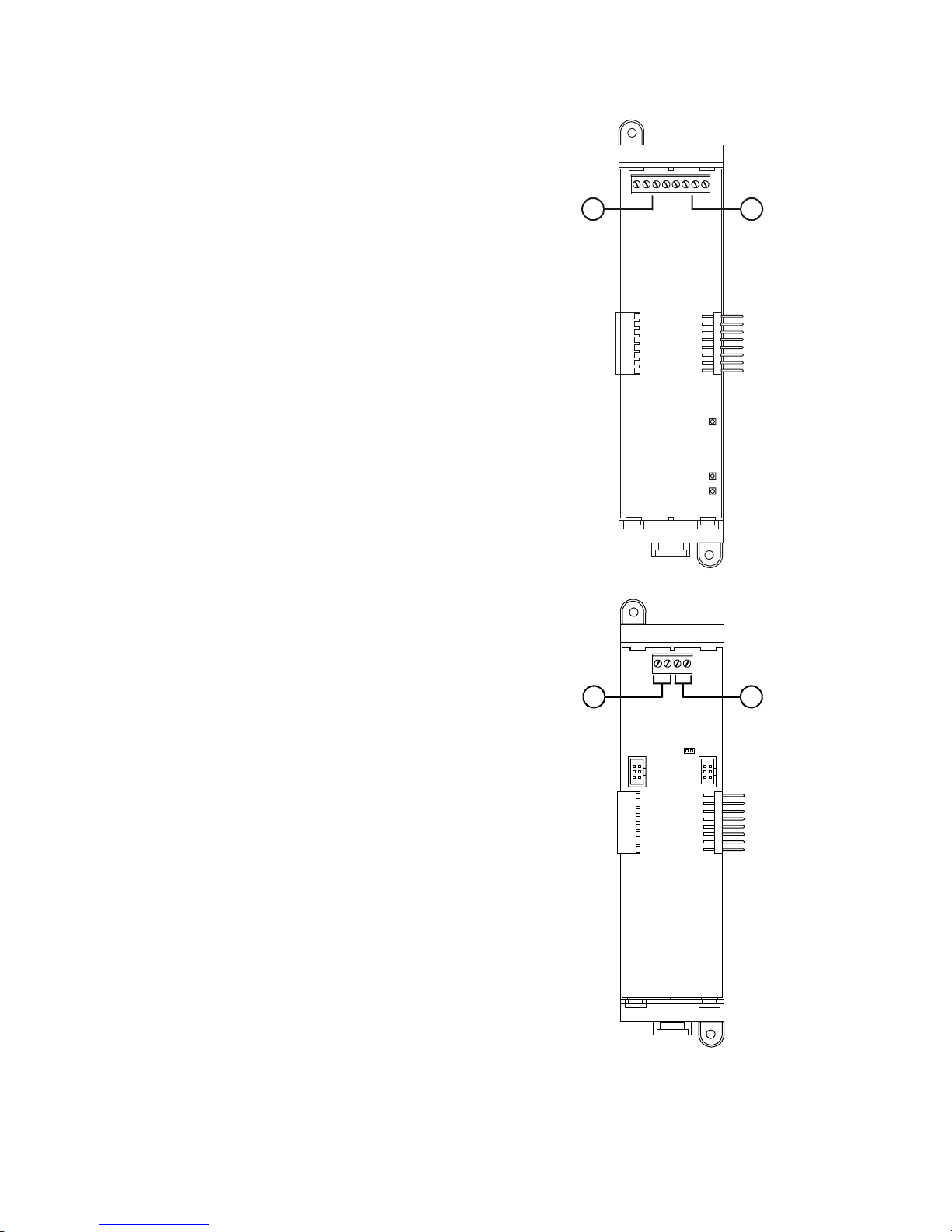
12
43
ZR8 Relay Card circuits
1. Dry-contact relays R1 – R4
Outputs: Normally-open or normally-closed contacts via jumper
selection
Contact rating: 24 Vdc @ 1.0 A
Wire size: 18 to 12 AWG (0.75 to 2.5 mm
Nonsupervised, and power-limited only when connected to a
power-limited source
2. Dry-contact relays R5 – R8
Outputs: Normally-open or normally-closed contacts via jumper
selection
Contact rating: 24 Vdc @ 1.0 A
Wire size: 18 to 12 AWG (0.75 to 2.5 mm
Nonsupervised, and power-limited only when connected to a
power-limited source
2
)
2
)
1
2
1.6 QS4 Technical Reference Manual
Technical Manuals Online! - http://www.tech-man.com
ZB16–4 Class B Conventional Zone Card circuits
1. IDC Circuits Z1 – Z12
Wiring configuration: Class B
Detector voltage: 20.33 – 24.76 Vdc, max ripple 2000 mV
Short circuit current: 75.9 mA, max.
Resistance: 50 Ω, max.
Capacitance: 100 µF, max
Wire size: 18 to 12 AWG (0.75 to 2.5 mm
End of line resistor: 4.7 kΩ, 1/2W
Supervised and power-limited
2. NAC Circuits Z13 – Z16
Wiring configuration: Class B
Output voltage: 24 Vdc, nominal
Output current: 2.0 A @ 24 Vdc
Wire size: 18 to 12 AWG (0.75 to 2.5 mm
End of line resistor: 10 kΩ, 1/2W
Supervised and power-limited
IDC specifications apply when programmed as IDC circuit
3. R1
Voltage: 24 Vdc, nominal
Wire size: 18 to 12 AWG (0.75 to 2.5 mm
4. R2
Voltage: 24 Vdc, nominal
Wire size: 18 to 12 AWG (0.75 to 2.5 mm
2
)
2
)
2
)
2
)
Product description
1
2
1
3
4
ZA8–2 Class A Conventional Zone Card circuits
1. IDC Circuits Zone 1 – Zone 3, Zone 5 – Zone 7
Wiring configuration: Class A
Detector voltage: 19.90 – 22.46 Vdc, max ripple 2000 mV
Short circuit current: 75.9 mA, max.
Resistance: 50 Ω, max.
Capacitance: 100 µF, max
Wire size: 18 to 12 AWG (0.75 to 2.5 mm2)
End of line resistor: 4.7 kΩ, 1/2W
Supervised and power-limited
2. NAC Circuits Zone 4, Zone 8
Wiring configuration: Class A
Output voltage: 24 Vdc, nominal
Output current: 2.0 A, 24 Vdc
Wire size: 18 to 12 AWG (0.75 to 2.5 mm
End of line resistor: 10 kΩ, 1/2W
Supervised and power-limited
IDC specifications apply when programmed as IDC circuit
3. NAC PWR IN (Zone 4)
Voltage: 24 Vdc, nominal
Wire size: 18 to 12 AWG (0.75 to 2.5 mm
4. NAC PWR IN (Zone 8)
Voltage: 24 Vdc, nominal
Wire size: 18 to 12 AWG (0.75 to 2.5 mm
2
)
2
)
2
)
1
3
2
2
1
4
QS4 Technical Reference Manual 1.7
Technical Manuals Online! - http://www.tech-man.com
Product description
DLD Dual Line Dialer Card circuits
1. Line #1
Supervised and nonpower-limited
2. Line #2
Supervised and nonpower-limited
12
RS485 (NT–A) Class A Card circuits
1. Secondary RS485 channel
Wire size: 18 to 12 AWG (0.75 to 2.5 mm
Supervised and power-limited
2. Primary RS485 channel
Wire size: 18 to 12 AWG (0.75 to 2.5 mm2)
Supervised and power-limited
Note: JP1 installed for ground fault detection on RS485 circuits.
2
)
12
1.8 QS4 Technical Reference Manual
Technical Manuals Online! - http://www.tech-man.com

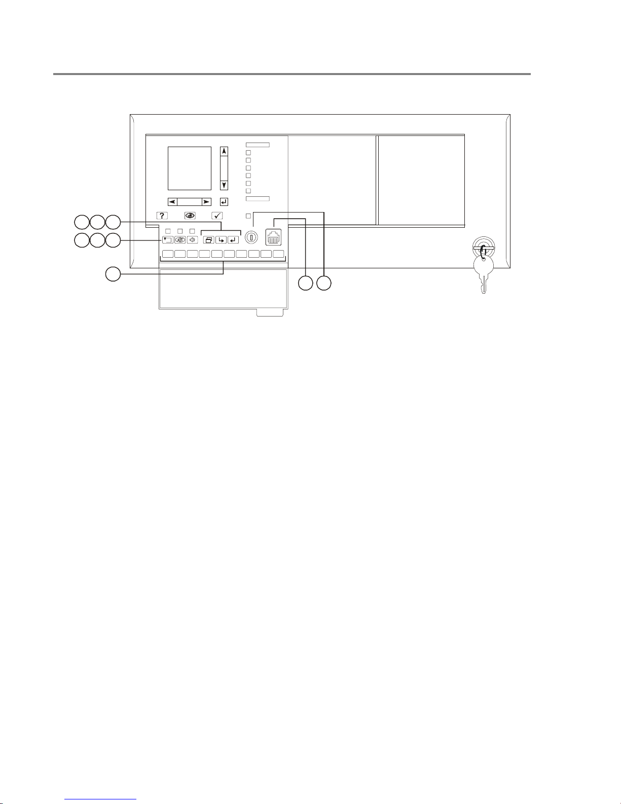
Controls and indicators
345 61 78
2
6
11
16
21
26
2
7
12
17
22
27
Product description
9
1
6
11
16
21
26
2
7
12
17
22
27
3
4
5
1234167890
12
11 10
5
1. Text display and controls: Displays system
messages, status information, programming
menus.
Moves the cursor up one line at a time or
to the previous record in the display
queue
Moves the cursor down one line at a time
or to the next record in the display queue
Moves the cursor right one character at a
time or to the next display queue
Moves the cursor left one character at a
time or to the previous display queue
Enters operator input and selects menu
items
2. Alarm LED: Indicates the panel posted an
alarm event record into the corresponding display
queue.
3. Supervisory LED: Indicates the panel posted
a supervisory event record into the corresponding
display queue.
4. Disable/Test LED: Indicates part of the
system is disabled or is currently under test.
Disabled components also signal a system
trouble.
3
8
13
18
23
28
9
14
19
24
29
10
15
20
25
30
8
13
18
23
28
4
9
14
19
24
29
5
10
15
20
25
30
5. Monitor LED: Indicates the panel posted a
monitor event record into the corresponding
display queue.
6. Trouble LED: Indicates the panel posted a
trouble event record into the corresponding
display queue.
7. Ground Fault LED: Indicates a ground fault in
the system wiring. Ground faults also signal a
system trouble.
8. CPU Fail LED: Indicates an unexpected
reboot or failure with the microprocessor. CPU
failures also signal a system trouble.
9. Power LED: Indicates the panel has ac power.
10. Panel Silence/Acknowledge button/LED:
Turns off the panel buzzer and acknowledges all
events. The Panel Silenced LED indicates that all
off normal events have been acknowledged and
the internal buzzer is off.
11. Status button: Displays the Status menu
from which you can identify active or disabled
points in the system.
12. Help button: Provides additional information
for the event record selected on the display.
QS4 Technical Reference Manual 1.9
Technical Manuals Online! - http://www.tech-man.com
Product description
Controls and indicators behind the flip-down cover
7
9
6
584
1234167890
5
3
1. Enable Controls key switch: Gives priority
access to control functions reserved for operators
with Level 2 access.
2. Barcode scanner jack: Input point for optional
barcode scanner.
3. Numeric keypad: Numbered buttons for
entering data and selecting menu options.
11
6
27
22
17
12
7
2
28
23
18
13
8
3
29
24
19
14
9
4
30
25
20
15
10
5
1
2
11
6
1
12
7
2
13
8
3
14
9
4
15
10
5
26
21
16
26
21
16
27
22
17
28
23
18
29
24
19
30
25
20
6. Drill button: Turns notification appliances on
according to the panel programming but does not
place the panel in alarm. The LED indicates
when the panel is in Drill mode.
7. Menu button: Displays the operator menus.
8. Delete button: Returns to the previous menu
or back spaces the cursor.
4. Reset button: Restores devices or zones in
alarm or trouble to their standby condition. The
LED indicates when the panel is resetting.
5. Alarm Silence button: Turns active
notification appliances off according to the panel
programming. Pressing Alarm Silence a second
time turns them back on. The LED indicates
when the panel is in alarm and operating with
notification appliances turned off.
9. Enter button: Press the Enter button to accept
information from the operator or continue to the
next item.
1.10 QS4 Technical Reference Manual
Technical Manuals Online! - http://www.tech-man.com

Controls and indicators on the zone annunciator card
21 3
1
6
11
16
21
26
2
7
12
17
22
27
3
8
13
18
23
28
4
9
14
19
24
29
5
10
15
20
25
30
Product description
1. Zone display button: Displays an event
record for each device in the corresponding zone
that signaled an alarm.
2. Zone active LED: Indicates a device in the
corresponding zone signaled an alarm condition.
3. Zone trouble LED: Indicates a device or
wiring fault in the corresponding Zone.
Note: ULC requires that every fire panel have the
capability to visually display system status by
means of specific indicators for each zone. All
status changes must clearly indicate that the
information is an Alarm (ALM), Supervisory
(SUP), Trouble (TBL), or Monitor (MON).
QS4 Technical Reference Manual 1.11
Technical Manuals Online! - http://www.tech-man.com

Product description
Interpretation of screen displays
HH:MM:SS MM/DD
System
Normal
Project Name
Alarm History:
nnnn
HH:MM:SS
Axxx Dxxx
nnn event name
Custom message 1
Custom message 2
This is what the panel display looks like when there are no event
records posted in a display queue.
HH:MM:SS is the current time in hours, minutes, and seconds
MM/DD is the current month and date
nnnn is the number times the panel went into alarm since being
placed into service
This is what the panel display looks like when there are event
records posted in a display queue.
HH:MM:SS is the current time in hours, minutes, and seconds
Axxx is the current number of active points
Dxxx is the current number of disabled points
nnn event name
Custom message 1
Custom message 2
ALM SUP TRBL MON
aaa sss ttt mmm
These items comprise the event record:
nnn is the posting sequence number (001 = first, 002 = second, and
so on)
event name is the event produced when the device changed states.
Refer to Table 1-1.
P:pp C:cc D:ddd is the address of the device that signaled the
event (P = panel number, C = card number, D = device number)
The event record may also include a custom message that typically
indicates the location of the device, depending on the panel
programming.
These items indicate the content of the display queues:
aaa is the number of alarm event records (highest priority)
sss is the number of supervisory event records
ttt is the number of trouble event records
mmm is the number of monitor event records (lowest priority)
1.12 QS4 Technical Reference Manual
Technical Manuals Online! - http://www.tech-man.com

Product description
Table 1-1: Event descriptions
Event name Event type Description
ALARM ACTIVE Alarm Smoke detector active
ALARM VERIFY Monitor Alarm active. Performing auto reset.
AND GROUP Alarm And group active
BAD PRSONATY Trouble SIGA personality mismatch
BAD TYPE Trouble SIGA type mismatch
COMM FAULT Trouble Communication failure
DEV COMPATIB Trouble SIGA compatibility fault
DIRTY HEAD Trouble Dirty smoke detector. No compensation remaining
DISAB SOUND Trouble Sounder is disabled (EN–54 only)
DISABLED Trouble Device is disabled
GROUND FAULT Trouble Ground fault
HEAT ALARM Alarm Heat detector active
INTERNAL TBL Trouble Internal system trouble
LCL MONITOR Monitor Common monitor
LCL TROUBLE Trouble Generic trouble.
MAINT ALERT Monitor Dirty smoke detector. Some compensation remaining
MATRIX GROUP Alarm Matrix group active
MONITOR Monitor Active non-latching input circuit.
OBJECT RUN Monitor Service group is enabled and governing all defined objects
PREALARM Monitor Possible fire condition exists.
PULL STATION Alarm Manual fire alarm box active
SERVICE GROUP Trouble Service group active
SUPERVISORY Supervisory A device used to monitor a component of the fire suppression system is active
SWITCH Monitor Operator presses switch on LED/Switch card
TAMPER Supervisory Sprinkler tamper active
TEST Trouble A member of a Service group under test is activated
TIME CONTROL Monitor Time control active
TROUBLE Trouble Common trouble
TROUBLE OPEN Trouble Open detected on a supervised output device's field wiring
TROUBLE SHORT Trouble Short detected on a supervised output device's field wiring
UNEXPECT DEV Trouble Signature device not defined in database
WATERFLOW Alarm Water flowing through the sprinkler system
ZONE ALARM Alarm Alarm zone active
ZONE MONITOR Monitor Monitor zone active
ZONE SUPER Supervisory Supervisory zone active
QS4 Technical Reference Manual 1.13
Technical Manuals Online! - http://www.tech-man.com

Product description
1.14 QS4 Technical Reference Manual
Technical Manuals Online! - http://www.tech-man.com

Chapter 2
Installation
Summary
This chapter provides instructions for installing the fire alarm control
panel.
Content
Installation do's and don'ts • 2.2
Installation checklist • 2.3
Two ways to install the cabinet: Surface or semi-flush mount • 2.4
How to assemble the panel • 2.6
Wiring mains ac and earth ground • 2.7
System jumper settings • 2.8
System addressing • 2.10
Terminal definitions • 2.14
Connecting a PT–1S printer • 2.22
Installing standby batteries • 2.23
Connecting a service computer • 2.24
QS4 Technical Reference Manual 2.1
Technical Manuals Online! - http://www.tech-man.com

Installation
Installation do's and don'ts
When installing cabinets... DO use fasteners that can support the full weight of the
cabinet and standby batteries. Tighten firmly to avoid
vibrations.
DO NOT drill inside the cabinet with circuit cards installed.
Remove all metal filings before installing the circuit cards.
DO NOT recess the cabinet into the wall deeper than 2–11/16
inches (68.2 mm) from the finished wall surface to allow room
for the trim kit.
When installing circuit boards... DO ground yourself with an approved static-protective wrist
strap when handling circuit boards.
DO keep circuit boards in their protective antistatic packaging.
Remove only for inspection or installation.
DO NOT touch component leads and connector pins when
handling circuit boards.
DO disconnect ac power and batteries before installing or
removing circuit boards. Installing or removing circuit boards
while the control panel is energized may damage the
equipment.
When installing circuit wiring...
When installing Signature loops... DO NOT install more than fifteen SIGA–UMs or MABs
When installing standby batteries... DO NOT install standby batteries until after you completely
DO use appropriately sized wire for the application.
Incorrectly-sized wires degrade circuit performance.
DO make sure there are no wire-to-ground shorts or wire-towire shorts before connecting field wires to the panel.
DO NOT over tighten screw terminals. Over tightening may
strip screw terminal threads and cause loose connections.
configured for two-wire smoke detectors on a loop.
DO NOT install more than seven SIGA–UMs or MABs
configured for two-wire smoke detectors on loops with isolator
devices.
DO NOT install more than ten SIGA–RELs on a loop. You
must use the QuickStart configuration utility to program a
SIGA–REL. Refer to the technical manual supplied with the
SIGA–REL and appendix C of this manual for programming
information.
install and test the system.
2.2 QS4 Technical Reference Manual
Technical Manuals Online! - http://www.tech-man.com

Installation checklist
Installation
¨ Prepare the site
¨ Unpack the equipment
¨ Install the cabinet
¨ Assemble the panel
¨ Wire mains ac and earth ground
Make sure the installation location is free from construction
dust and debris, and immune to extreme temperature ranges
and humidity.
Allow enough floor and wall space so the panel can be
installed and serviced without obstructions.
Pull and tag all field wiring. See Appendix A for wire length
calculations.
Open the shipping container and carefully unpack the
equipment. Check for any visible signs of damage. If there is
any damage, return the equipment to the place of purchase.
Keep the container and packing material until after completely
installing and testing the equipment. Use the shipping
container to return the equipment to the manufacturer.
Verify the shipping container contains the correct parts. If any
parts are missing or damaged, return the equipment to the
manufacturer.
See Figure 2-1 for cabinet dimensions.
Bring the primary power conductors into the left side
(nonpower-limited area) of the cabinet and wire to the ac
terminal block.
¨ Connect the field wiring
¨ Use the AutoLearn and
AutoLoop utilities to configure
the system
¨ Customize the system
configuration
¨ Install the standby batteries
WARNING: Make sure that the circuit breaker providing ac
power is switched off before connecting wires to the terminal
block.
Bring the field wiring into the power-limited area of the cabinet.
Verify there are no open or shorts then connect the wires to
their respective terminals.
Refer to chapter 4.
Refer to chapter 4.
Do not connect standby batteries to the panel until after
completely testing the panel.
QS4 Technical Reference Manual 2.3
Technical Manuals Online! - http://www.tech-man.com

Installation
Two ways to install the cabinet: Surface or semi-flush mount
Surface mount instructions
1. Position the cabinet on the
finished wall surface.
2. Fasten the cabinet to the
wall surface where
indicated. Tighten firmly.
Semi-flush mount
instructions
1. Frame the interior wall as
required to support the full
weight of the cabinet and
standby batteries.
4-7/8 in
(123.8 mm)
2-11/16 in
(68.2 mm)
2-3/16 in
(55.6 mm)
2. Fasten the cabinet to the
framing studs where
indicated. Tighten firmly.
2.4 QS4 Technical Reference Manual
Technical Manuals Online! - http://www.tech-man.com
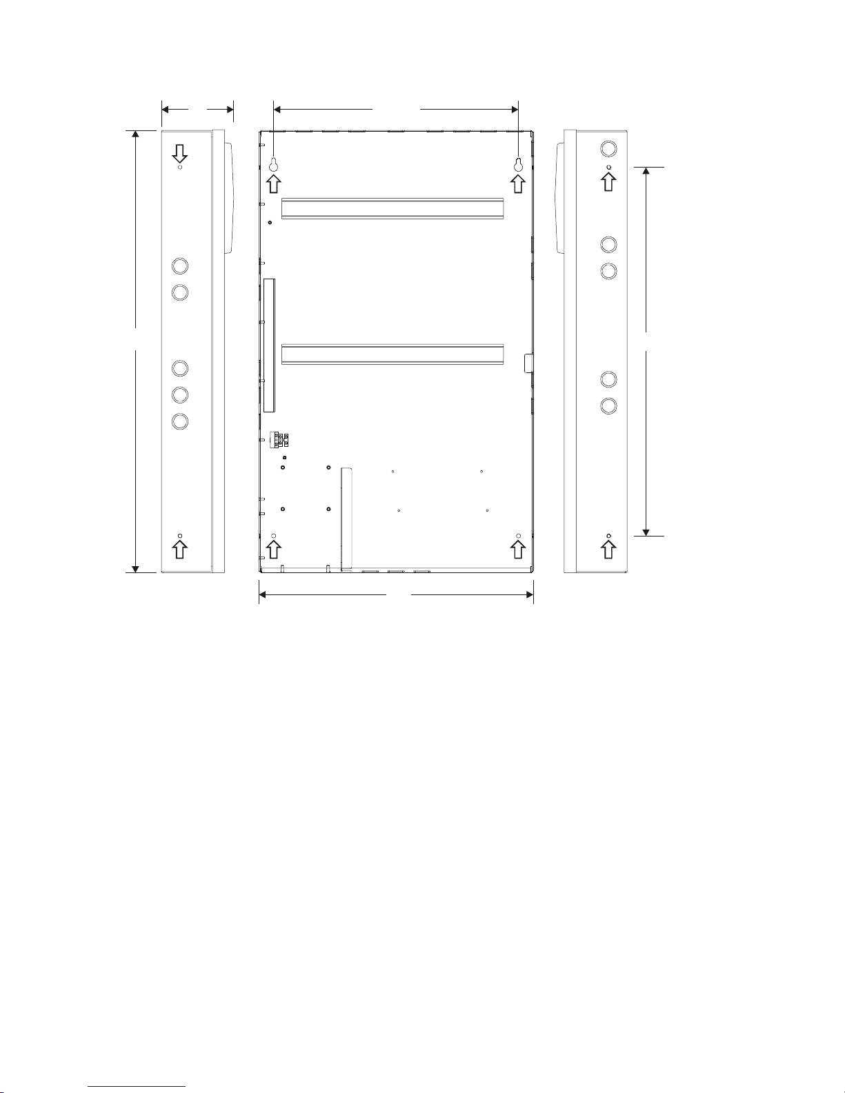
D3 D4
Installation
D1
5-option
cabinet
D5
D2
Dimensions
D1 D2 D3 D4 D5
18 in
(45.72 cm)
18-5/8 in
(47.31 cm)
4-7/8 in
(12.38 cm)
16-5/8 in
(42.23 cm)
13 in
(33.00 cm)
12-option
cabinet
30 in
(76.2 cm)
18-5/8 in
(47.31 cm)
Note: Add 1-1/2 in (3.81 cm) to D1 and D2 dimensions for trim kit.
Figure 2-1: Dimensions for 5-option and 12-option cabinets (arrows show mounting hole locations)
QS4 Technical Reference Manual 2.5
Technical Manuals Online! - http://www.tech-man.com
4-7/8 in
(12.38 cm)
16-5/8 in
(42.23 cm)
25 in
(63.50 cm)

Installation
How to assemble the panel
Circuit card instructions
1. Lock the PS6 onto the DIN rail and configure
jumpers.
2. Attach the ground wire to the cabinet. Tighten
the lock nut firmly to ensure a good
mechanical and electrical connection.
3. Plug the transformer into the PS6.
4. Install remaining option cards according to
their respective installation sheets.
Use a QS–Cable12 to connect option cards on
the top and bottom DIN rails in a 12-option
cabinet.
Door mounting instructions
1. Bolt the door to the cabinet back box.
2. Attach one end of the ground strap to the door
and the other to the back box.
3. Screw the CPU/Display unit to the cabinet
door.
4. Plug one end of the ribbon cable into the
CPU/Display and the other end into the PS6.
5. Screw the key switch ground wire and the
CPU cover to the cabinet door.
*Actual cabinet door not shown
2.6 QS4 Technical Reference Manual
Technical Manuals Online! - http://www.tech-man.com

Wiring mains ac and earth ground
Installation
H
(L1)
G
(E)
N
(L2)
CAUTION: The middle connection on the ac
terminal block makes a mechanical connection
to chassis (earth) ground. Do not allow the ac
hot and neutral conductors to make contact with
the middle connector on the ac terminal block.
Wiring instructions
1. Bring the mains ac conductors into the
cabinet through the 3/4–1/2 inch combination
knock-outs on the left side or upper left
corner of the cabinet.
2. Wire the hot (H, L1), neutral (N, L2), and
ground (G, E) conductors to the ac terminal
block as shown.
Notes
Keep power-limited wires in the shaded area
and nonpower-limited wires in the nonshaded
area.
Maintain a 1/4-inch separation between the
mains ac and battery wires (power-limited) and
and all other nonpower-limited wiring at all
times.
3. Insert tabbed end of terminal block cover
(deadfront) into the slot provided on the side
of the cabinet.
QS4 Technical Reference Manual 2.7
Technical Manuals Online! - http://www.tech-man.com

Installation
System jumper settings
PS6 Power Supply Card jumpers
JP2 configures the Smoke/Accessory power
output for constant or resettable 24 Vdc.
• Set JP2 to ACC PWR to provide constant
24 Vdc for external equipment.
• Set JP2 to SMK PWR to provide resettable
24 Vdc for four-wire smoke detectors
JP1 configures the panel for failsafe operation.
Failsafe allows the system to generate output
responses even when the CPU loses
communication with the power supply card.
• Set JP1 to ON to turn failsafe mode on
JP2
ACC PWR
SMK PWR
JP1
• Set JP1 to OFF to turn failsafe mode off
SLIC Signature Loop Intelligent Controller
Card jumpers
JP1 and JP2 selects the signal that the SLIC
uses for the notification appliances connected to
NAC1.
Note: NAC 2 always uses the external signal
connected to TB2–3 and TB2–4.
• Set JP1 and JP2 to INT to use the 24 Vdc
that comes from the PS6 over the bus
connection.
• Set JP1 and JP2 to EXT to use the 24 Vdc
that comes from an external source
connected to TB2–3 and TB2–4.
ON OFF
JP1 JP2
EXT
INT
CAUTION: Do not set JP1 and JP2 to EXT if
strobes are connected to NAC 1 and a coded
signal is connected to TB2–3 and TB2–4.
2.8 QS4 Technical Reference Manual
Technical Manuals Online! - http://www.tech-man.com

ZR8 Relay Card jumpers
JP1 – JP8 configure which relay contacts are
present on the terminal connections for R1 – R8,
respectively.
The normal operating state of the relay (on or off
when the panel is normal) determines whether
the terminal connections are normally-open or
normally-closed.
The figure to the right shows the relay contact
positions when the relay is turned off.
Installation
R4+ R4–
JP4
RS485 (NT–A) Class A Card jumpers
JP1 configures ground fault supervision for
Class A remote annunciators.
• Set a shorting plug across JP1–1 and JP1–2
when the PS6 powers the remote
annunciator and provides ground fault
supervision
• Set a shorting plug across JP1–2 and JP1–3
when an external supply powers the remote
annunciator and provides ground fault
supervision
123
JP1
QS4 Technical Reference Manual 2.9
Technical Manuals Online! - http://www.tech-man.com
Installation
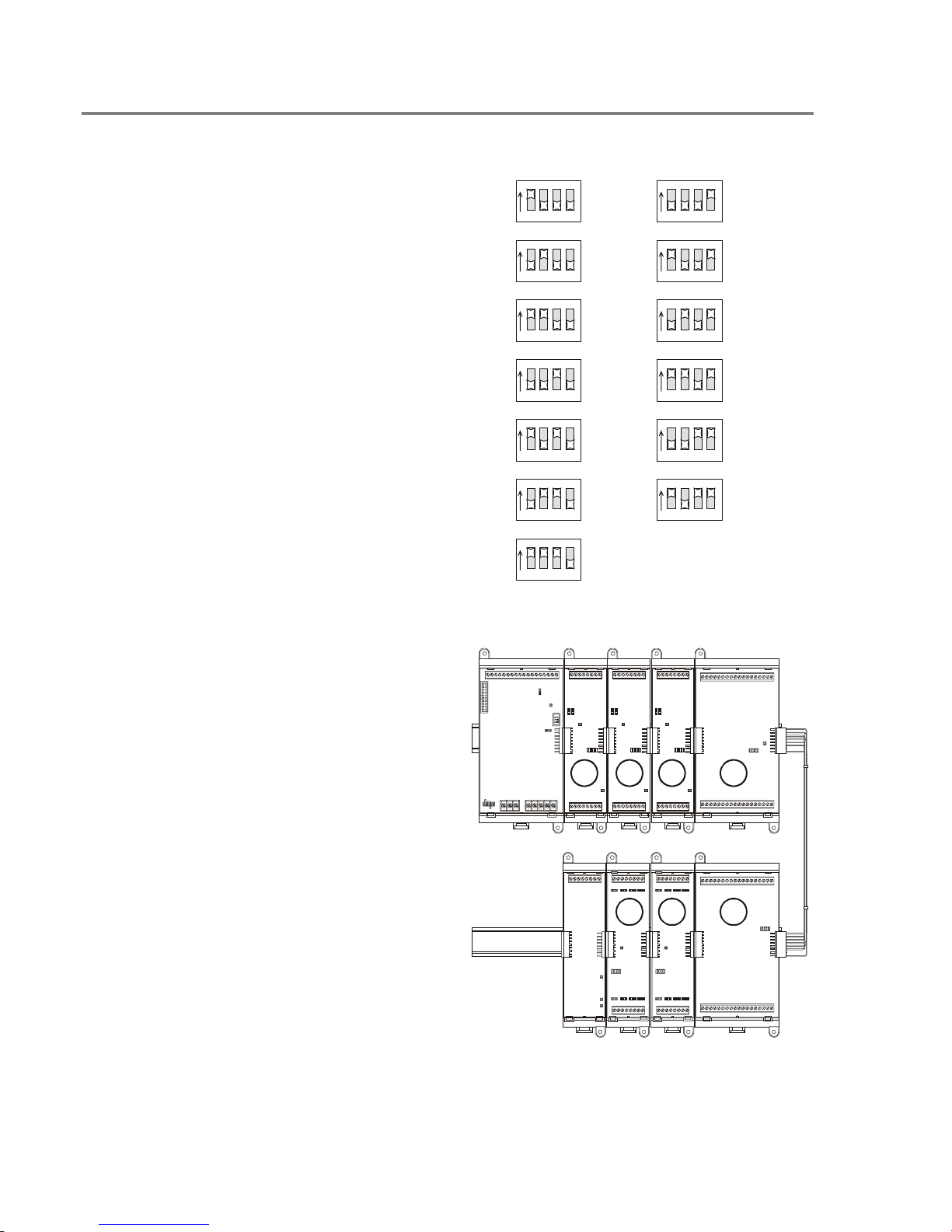
System addressing
Card addresses
Each option card installed in the panel is
assigned a unique card address. Only the SLIC,
ZB16–8, ZA8–2, and ZR–8 have card addresses
that you can set. The CPU, DLD and PS6 card
addresses are fixed.
00: Reserved for the CPU
01–07: Used for the SLIC, ZB16–8, ZA8–2, and
ZR–8
08–13: Used for the ZB16–8, ZA8–2, and ZR–8
14: Reserved for the DLD
15: Reserved for the PS6
ON
1234
ON
1234
ON
1234
ON
1234
ON
1234
ON
1234
ON
1234
= 01
= 02
= 03
= 04
= 05
= 06
= 07
ON
= 08
123 4
ON
= 09
123 4
ON
= 10
123 4
ON
= 11
123 4
ON
= 12
123 4
ON
= 13
123 4
Tip: When you install the option cards, set the
card addresses in consecutive order as you
move away from the power supply starting at
address 01.
01 02 03 04
07 06 05
2.10 QS4 Technical Reference Manual
Technical Manuals Online! - http://www.tech-man.com
Installation
SLIC Signature Loop Intelligent Controller
Card device addresses
The device address format is PPCCDDD,
where:
PP is the panel number (01)
CC is the card number (any number between 1
and 7 depending on the setting of SW1)
DDD is the device or circuit number, where:
• 001–125 are Signature automatic detectors
and SIGA–IM isolator modules
• 126–250 are Signature modules
• 270 is the NAC 1 output circuit
• 271 is the NAC 2 output circuit
Note: Some Signature modules use two or more
device addresses.
PPCC270
PPCC271
PPCC001
to
PPCC125
PPCC126
to
PPCC250
ZR8 Relay Card device addresses
The device address format is PPCCDDD,
where:
PP is the panel number (01)
CC is the card number (any number between 1
and 13 depending on the setting of SW1)
DDD is the device number, where 001 – 008 are
relays 1 – 8, respectively
PPCC002
PPCC001
PPCC006
PPCC005
PPCC003
PPCC004
PPCC007
PPCC008
QS4 Technical Reference Manual 2.11
Technical Manuals Online! - http://www.tech-man.com
Installation
ZB16–4 Class B Conventional Zone Card
device addresses
The device address format is PPCCDDD,
where:
PP is the panel number (01)
CC is the card number (any number between
1 and 13 depending on the setting of SW1)
DDD is the circuit number, where:
• 001 – 012 are IDC circuits Z1 – Z12,
respectively
• 013 – 016 are NAC circuits Z13 – Z16,
respectively
Note: NAC circuits Z13 – Z16 can also be
programmed as IDC circuits.
PPCC005
PPCC004
PPCC003
PPCC002
PPCC001
PPCC012
PPCC011
PPCC010
PPCC006
PPCC007
PPCC008
PPCC009
PPCC013
PPCC014
PPCC015
PPCC016
ZA8–2 Class A Conventional Zone Card
device addresses
The device address format is PPCCDDD,
where:
PP is the panel number (01)
CC is the card number (any number between
1 and 13 depending on the setting of SW1)
DDD is the circuit number, where:
• 001 – 003 and 005 – 007 are IDC circuits
Zone 1 – Zone 3 and Zone 5 – Zone 7,
respectively
• 004 and 008 are NAC circuits Zone 4 and
Zone 8, respectively
Note: NAC circuits Zone 4 and Zone 8 can
also be programmed as IDC circuits.
PPCC002
PPCC001
PPCC006
PPCC005
PPCC003
PPCC004
PPCC007
PPCC008
2.12 QS4 Technical Reference Manual
Technical Manuals Online! - http://www.tech-man.com
Installation
SL30 (–1) LED/Switch Card device
addresses
The device address format is GGSS for
switches and GGSSL for LEDs, where:
GG is the group number (01 for SL30, 02 for
SL30–1)
SS is the switch number
L is the LED number, where:
• 1 is the red Alarm LED
• 2 is the yellow Active LED
• 3 is the yellow Trouble LED
GG011, GG012
GG02
GG03
GG04
GG013
1
06-10 11-15 16-20 21-25 26-30
3 8 13 18 23 28
GG01
611162126
7121722272
9141924294
GG05
GG01
GG02
GG03
GG04
GG05
10 15 20 25 305
SL30
06-10 11-15 16-20 21-25 26-30
01-05
3631
32
33 38 43 48 53 58
37 42 47 52 57
39 44 49 54 5934
40 45 50 55 6035
41 46 51 56
QS4 Technical Reference Manual 2.13
Technical Manuals Online! - http://www.tech-man.com
SL30–1

Installation
Terminal definitions
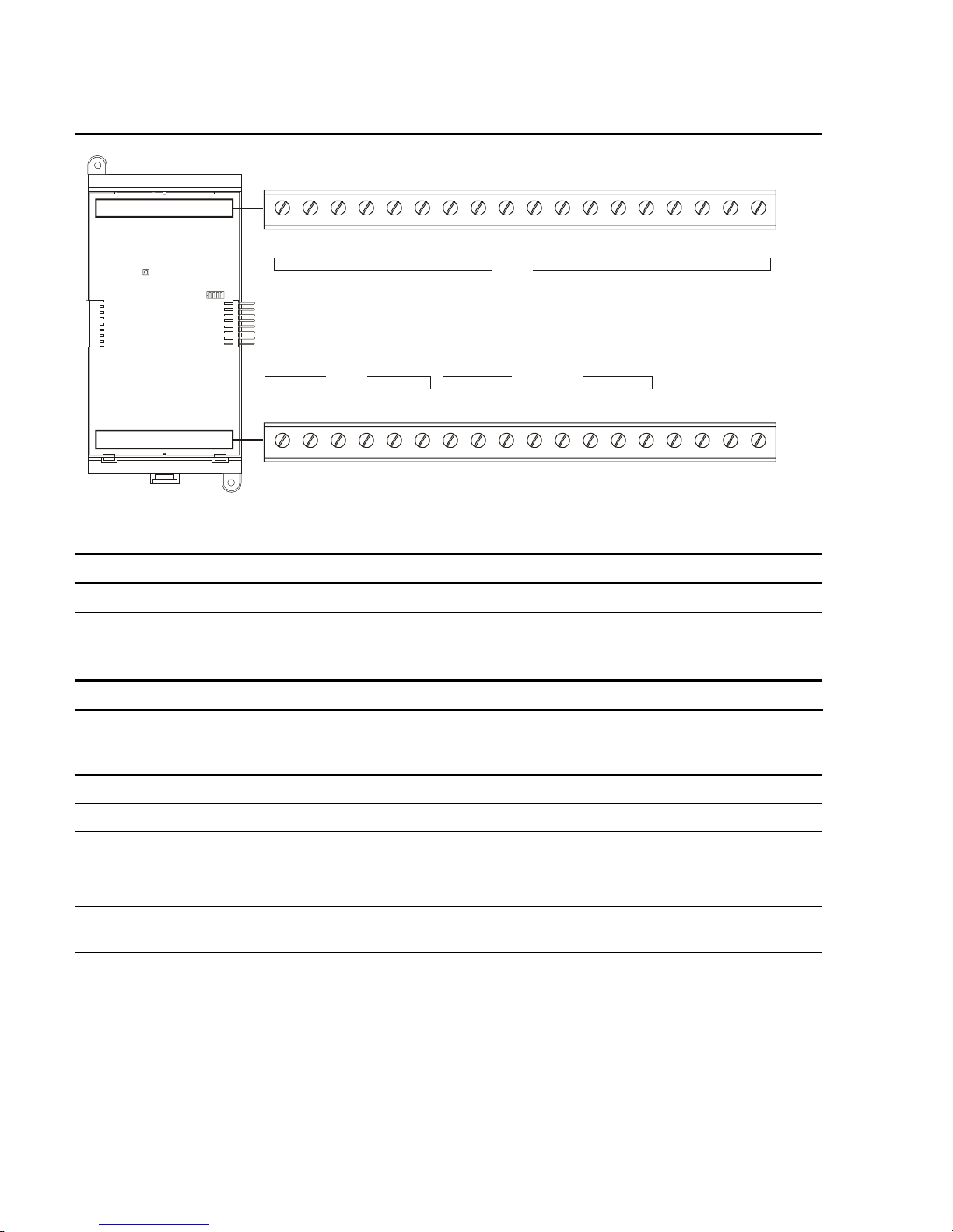
Table 2-1: PS6 Power Supply card terminal definitions
NO C NC C NO C NO C NO N.C. RTS TX RX COM
1 18171615141312111098765432
SMOKE
ACC PWRRELAY 1 RELAY 2 RELAY 3 RELAY 4 RS485 RS232
–
+
–
+
TB1
BATT PWR
AUX1 AUX2 COM AUX3 COM
+
1
15432
–
NC
3
2
AUX POWER
TB2
TB3
Terminal No. Name Description
TB1–1, –2 Relay 1 NO, C Normally-open relay contacts that close automatically when
the panel processes an alarm event. The contacts remain
closed until all active alarm points restore and the panel
resets.
TB1–2, –3 Relay 1 C, NC Normally-closed relay contacts that open automatically when
the panel processes an alarm event. The contacts remain
open until all active alarm points restore and the panel
resets.
TB1–4, –5 Relay 2 C, NO
Normally-open relay contacts that close automatically when
the panel processes a supervisory event. The contacts
remain closed until the active supervisory point restores.
TB1–6, –7 Relay 3 C, NO Normally-open relay contacts that close automatically when
the panel energizes. The contacts open when the panel
processes a trouble event or when the panel loses power
and remain open until the trouble condition restores.
TB1–8, –9 Relay 4 C, NO Normally-open relay contacts that close depending on how
the user programs the panel.
TB1–10 N.C. Not used
TB1–11, –12 SMK/ACC PWR +, –
Provides regulated 24 Vdc for four-wire smoke detectors or
accessory devices depending on jumper setting.
TB1–13, –14 RS485 +, – Connects to the Channel 1 input on a remote annunciator
2.14 QS4 Technical Reference Manual
Technical Manuals Online! - http://www.tech-man.com

Terminal No. Name Description
TB1–15 RS232 RTS Not used
Installation
TB1–16 RS232 RX
TB1–17 RS232 TX
TB1–18 RS232 COM Connects to the common ground (COM) terminal on a
TB2–1 BATT PWR + Connects to the positive terminal on the standby battery.
TB2–2 BATT PWR – Connects to the negative terminal on the standby battery.
TB2–3 NC Not used.
TB3–1 AUX1 Provides 24 Vdc, FWR power to auxiliary devices.
TB3–2 AUX2 Provides 24 Vdc, FWR power to auxiliary devices.
TB3–3 COM Negative reference for AUX1 and AUX2 outputs.
TB3–4 AUX3 Provides 24 Vdc, FWR power to auxiliary devices.
TB3–5 COM Negative reference for AUX3 output.
Connects to the data transmit (TX) terminal on a peripheral
device.
Connects to the receive data (RX) terminal on a peripheral
device.
peripheral device.
Note: AUX1, AUX2, and AUX3 can not be used to power
remote annunciators
QS4 Technical Reference Manual 2.15
Technical Manuals Online! - http://www.tech-man.com

Installation
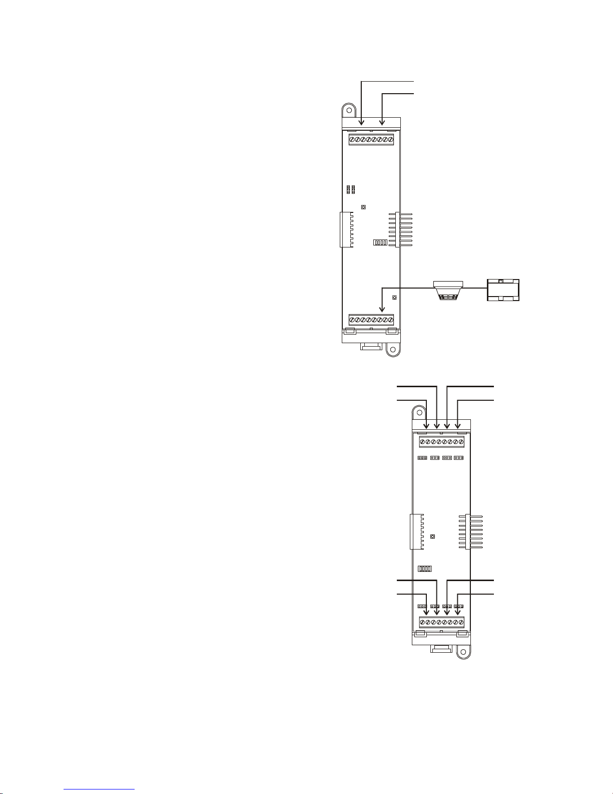
Table 2-2: SLIC Signature Loop Intelligent Controller card
NAC 1 NAC 2
B+ B– A+ A– B+ B– A+ A–
18765432
TB1
OUT LOOPIN
+
–
18765432
+
A+ A– B+ B–
–
TB2
Terminal No. Name Description
TB–1, –2 NAC 1 B+, B– Connects to the IN +/– terminals of the first device on the
NAC circuit. Polarity markings (+/–) indicate output signal
polarity with the circuit turned off. Polarity reverses with the
circuit turned on.
TB–3, –4 NAC 1 A+, A– Connects to the OUT +/– terminals of the last device on the
NAC circuit. Class A configuration only.
TB–5, –6 NAC 2 B+, B– Connects to the IN +/– terminals of the first device on the
NAC circuit. Polarity markings (+/–) indicate output signal
polarity with the circuit turned off. Polarity reverses with the
circuit turned on.
TB–7, –8 NAC 2 A+, A–
Connects to the OUT +/– terminals of the last device on the
NAC circuit. Class A configuration only.
TB2–1, –2 OUT+, OUT–
Connects to the next device on the same 24VDC riser used
to provide 24 Vdc to NAC 1 and NAC 2.
TB2–3, –4 IN+, IN–
Connects to the signal source used to provide 24 Vdc to
NAC 1 and NAC 2.
TB2–5, –6 LOOP A+, A– Connects to the DATA OUT +/– terminals of last device on
the Signature signaling line circuit. Class A configuration
only.
TB2–7, –8 LOOP B+, B– Connects to the DATA IN +/– terminals of the first device on
the Signature signaling line circuit.
2.16 QS4 Technical Reference Manual
Technical Manuals Online! - http://www.tech-man.com

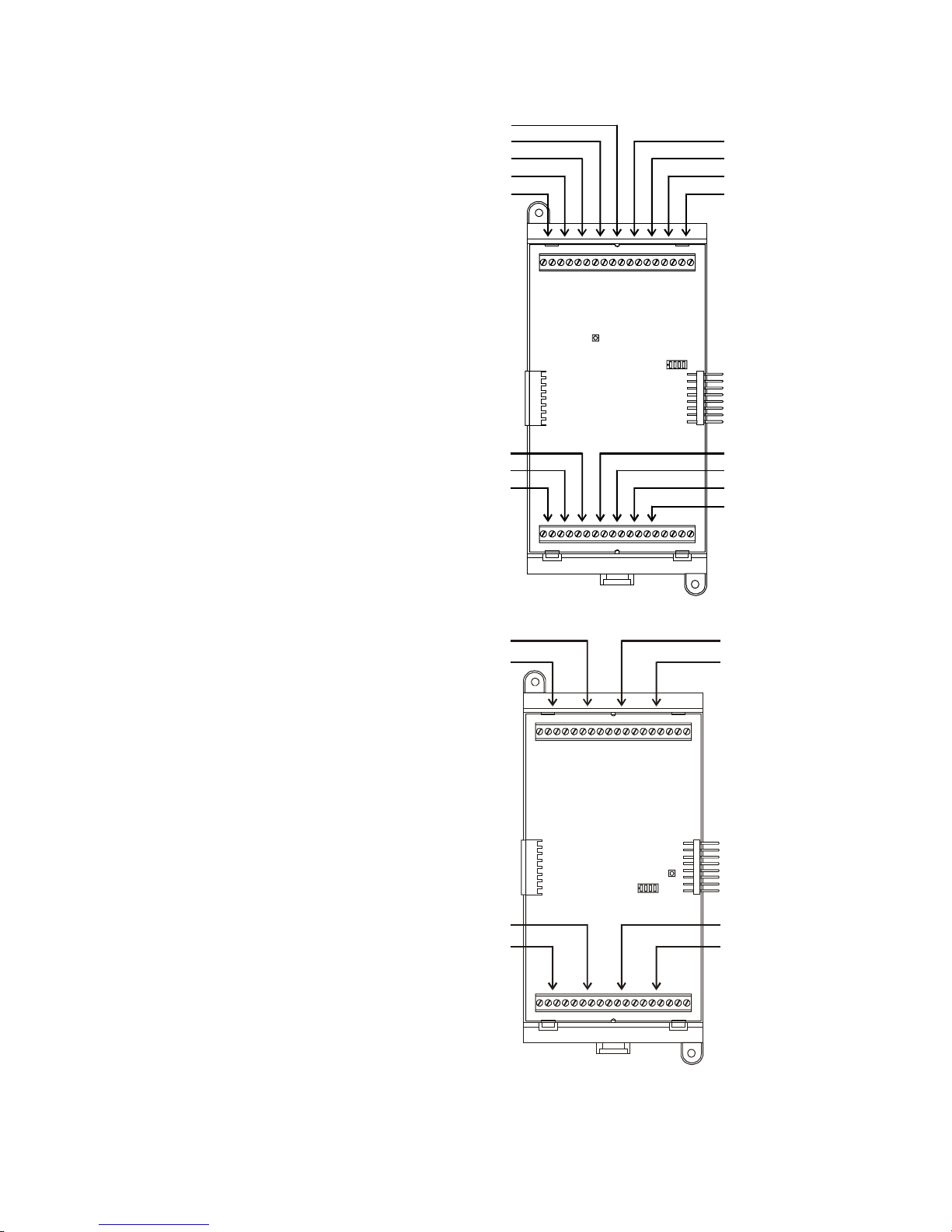
Table 2-3: ZA8–2 terminal definitions
Installation
ZONE 1
B+ B– A+ A–
1 18171615141312111098765432
ZONE 5
B+ B– A+ A–
1 18171615141312111098765432
ZONE 2
B+ B– A+ A–
IDC
IDC
ZONE 6
B+ B– A+ A–
ZONE 3
B+ B– A+ A–
ZONE 7
B+ B– A+ A–
ZONE 4
B+ B– A+ A–
IDC/NAC
IDC/NAC
ZONE 8
B+ B– A+ A–
NAC PWR
IN+ IN–
NAC PWR
IN+ IN–
IDC circuit connections
Terminal No. Name Description
TB1–1, –2 ZONE 1 B+, B– Connects to the IN +/– terminals of the first device on the IDC.
TB1
TB2
TB1–3, –4 ZONE 1 A+, A–
Connects to the OUT +/– terminals of the last device on the
IDC.
Note: ZONE 2, 3, 5, 6, and 7 connect the same as described for ZONE 1.
IDC/NAC circuit connections
Terminal No. Name Description
TB1–13, –14 ZONE 4 B+, B–
Connects to the IN +/– terminals of the first device on the NAC.
Polarity markings (+/–) indicate output signal polarity with the
circuit turned off. Polarity reverses with the circuit turned on.
TB1–15, –16 ZONE 4 A+, A– Connects to the OUT +/– terminals of the last device on the
NAC.
TB1–17, –18 NAC PWR IN+, IN–
Connects to the signal source used to provide 24VDC to ZONE
4.
TB2–13, –14 ZONE 8 B+, B– Connects to the IN +/– terminals of the first device on the NAC.
Polarity markings (+/–) indicate output signal polarity with the
circuit turned off. Polarity reverses with the circuit turned on.
TB2–15, –16 ZONE 8 A+, A– Connects to the OUT +/– terminals of the last device on the
NAC.
TB2–17, –18 NAC PWR IN+, IN–
Connects to the signal source used to provide 24VDC to ZONE
8.
Note: ZONE 4 and ZONE 8 may be programmed as IDC circuits.
QS4 Technical Reference Manual 2.17
Technical Manuals Online! - http://www.tech-man.com
Installation
Table 2-4: ZB16–4 Class B Zone card terminal definitions
+ Z1 – + Z2 – + Z3 – + Z4 – + Z5 – + Z6 – + Z7 – + Z8 – + Z9 –
1 18171615141312111098765432
IDC IDC/NAC
TB1
IDC
+ Z10 –
1 18171615141312111098765432
+ Z11 – + Z12 – + Z13 – + Z14 – + Z15 – + Z16 – + R1 – + R2 –
IDC circuit connections
Terminal No. Name Description
TB1–1, –2 Z1+, Z1– Connects to the IN +/– terminals of the first device on the IDC.
Note: Z2–Z16 connect the same as described for Z1.
IDC/NAC circuit connections
Terminal No. Name Description
TB2–7, –8 Z13+, Z13–
Connects to the IN +/– terminals of the first device on the NAC.
Polarity markings (+/–) indicate output signal polarity with the
circuit turned off. Polarity reverses with the circuit turned on.
TB2–9, –10 Z14+, Z14– same as above
TB2–11, –12 Z15+, Z15– same as above
TB2–13, –14 Z16+, Z16– same as above
TB2
TB1–15, –16 R1+, R1– Connects to the signal source used to provide 24VDC to Z13 and
Z14.
TB1–17, –18 R2+, R2– Connects to the signal source used to provide 24VDC to Z15 and
Z16.
Note: Z13, Z14, Z15, and Z16 may be programmed as IDC circuits.
2.18 QS4 Technical Reference Manual
Technical Manuals Online! - http://www.tech-man.com
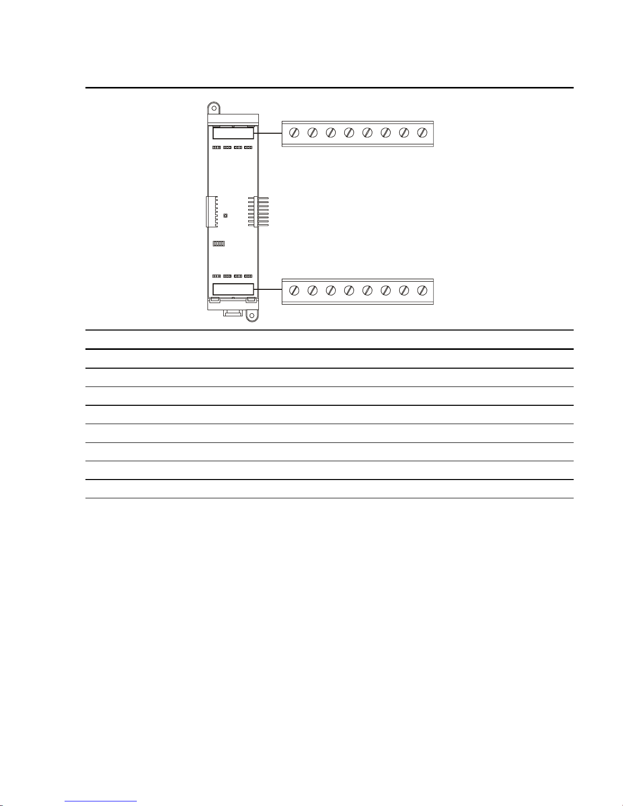
Table 2-5: ZR8 Relay card terminal definitions
Installation
+ R1 –
18765432
+ R5 – + R6 – + R7 – + R8 –
18765432
+ R2 – + R3 – + R4 –
Terminal No. Name Description
TB1–1, –2 R1+, R1– Terminal connections for relay 1.
TB1–3, –4 R2+, R2– Terminal connections for relay 2.
TB1–5, –6 R3+, R3– Terminal connections for relay 3.
TB1
TB2
TB1–7, –8 R4+, R4– Terminal connections for relay 4.
TB2–1, –2 R5+, R5– Terminal connections for relay 5.
TB2–3, –4 R6+, R6– Terminal connections for relay 6.
TB2–5, –6 R7+, R7– Terminal connections for relay 7.
TB2–7, –8 R8+, R8– Terminal connections for relay 8.
QS4 Technical Reference Manual 2.19
Technical Manuals Online! - http://www.tech-man.com

Installation
Table 2-6: RS485 (NT–A) Class A card terminal definitions
RS485
+ CH2 –
1432
+ CH1 –
TB1
Terminal No. Name Description
TB1–1, –2 CH2+, CH2– Connects to CH2+/– on the first remote annunciator on the Class
A RS485 riser.
TB1–3, –4 CH1+, CH1– Connects to CH1+/– on the first remote annunciator on the Class
A RS485 riser.
2.20 QS4 Technical Reference Manual
Technical Manuals Online! - http://www.tech-man.com

Table 2-7: DLD Dual Line Dialer card terminal definitions
LINE 1 LINE 2
IN OUT IN OUT
TIP RING TIP RING TIP RING TIP RING
Installation
TB1
1432
5876
Terminal No. Name Description
TB1–1 LINE 1 TIP IN Connects to the Tip In connector on the telco side of an RJ31X
block via an RJ–12 modular cable.
TB1–2 LINE 1 RING IN Connects to the Ring In connector on the telco side of an
RJ31X block via an RJ–12 modular cable.
TB1–3 LINE 1 TIP OUT Connects to the Tip Out connector on the protected premises
side of an RJ31X block via an RJ–12 modular cable.
TB1–4 LINE 1 RING OUT Connects to the Ring Out connector on the protected premises
of an RJ31X block via an RJ–12 modular cable.
TB1–5 LINE 2 TIP IN
Connects to the Tip In connector on the telco side of an RJ31X
block via an RJ–12 modular cable.
TB1–6 LINE 2 RING IN
Connects to the Ring In connector on the telco side of an
RJ31X block via an RJ–12 modular cable.
TB1–7 LINE 2 TIP OUT
Connects to the Tip Out connector on the protected premises
side of an RJ31X block via an RJ–12 modular cable.
TB1–8 LINE 2 RING OUT Connects to the Ring Out connector on the protected premises
of an RJ31X block via an RJ–12 modular cable.
QS4 Technical Reference Manual 2.21
Technical Manuals Online! - http://www.tech-man.com

Installation
Connecting a PT–1S printer
For control panels with only a printer
1. Locate the printer in the same room as and
within 20 ft of the panel (printer wiring is
nonsupervised and power-limited).
2. Wire the printer cable to the RS232
connections on the power supply card then
plug the cable into the printer.
3. Set the printer switches for 9600 bps, 8 bits,
no parity. Refer to the documentation
included with the printer for more details.
For control panels with a printer and a CDR–
3 Bell Coder module
1. Install the IOP3A in the same enclosure as
the CDR–3. Refer to appendix B.
2. Wire the IOP3A to the CDR–3.
3. Wire the printer cable to the RS232
connections on the IOP3A then plug the
cable into the printer.
4. Configure the IOP3A as follows:
PS6 TB1–18
PS6 TB1–17
PS6 TB1–16
CDR–3 TB2–4
CDR–3 TB2–5
CDR–3 TB2–6
CDR–3 TB2–7
PS6 TB1–17
COM–COM
TX–RX
RX–TX
7
3
2
DB–25P
REAR VIEW
TB1
S
W
1
TO
PT–1S
1
2
3
4
5
6
U
1
P
J
B
1
3
2
JP1 = 2–3
JP2 = ON
JP3 = ON
JP4 = ON
SW1 = UP
5. Set the printer switches for 9600 bps, 8 bits,
no parity. Refer to the documentation
included with the printer for more details.
DB–25P
REAR VIEW
TO
PT–1S
732
COM–COM
RxD–TxD
TxD–RxD
TB3
IOP3A
J
J
B
B
2
3
1
2
3
4
TB2
J
B
4
2.22 QS4 Technical Reference Manual
Technical Manuals Online! - http://www.tech-man.com

Installing standby batteries
–
–+–
–
For batteries rated at 10 Ah
or less
1. Place the batteries in the
bottom of the control panel.
2. Wire the batteries to the
PS6.
Notes
Do not run wires through the
bottom knock-outs when
batteries are installed in the
control panel.
Battery wiring is supervised
and nonpower-limited.
Maintain a 1/4-inch
separation between powerlimited and nonpower-limited
wiring at all times.
Installation
+
For batteries rated greater
than 10 Ah
1. Place the batteries in a
BC-1 Battery Cabinet. The
cabinet must be mounted
within 3 ft of the control
panel, in the same room,
and connected with conduit.
2. Wire the batteries to the
PS6.
Note: Install, maintain, and test
standby batteries in
accordance with NFPA 72.
BC-1
+
+
QS4 Technical Reference Manual 2.23
Technical Manuals Online! - http://www.tech-man.com

Installation
Connecting a service computer
Connection of a service computer to the
control panel requires programming
cable P/N 260097, ordered separately.
Connection of a service computer to a
remote annunciator requires
programming cable P/N 360136 and a
RJ–11 to DB9 adapter P/N 240507,
both ordered separately.
PS6
RTS
RX
TX
COM
NOT USED
DB-9F
REAR VIEW
1
9
P/N 260097
2.24 QS4 Technical Reference Manual
Technical Manuals Online! - http://www.tech-man.com

Chapter 3
Operating instructions
Summary
This chapter provides instructions for operating the control panel.
Content
Instructions for the Level 1 operator (public mode access) • 3.2
Instructions for the Level 2 operator (emergency mode access) • 3.5
Instructions for the Level 3 operator (maintenance mode access) • 3.7
Instructions for the Level 4 operator (service mode access) • 3.10
QuickReference list • 3.11
QS4 Technical Reference Manual 3.1
Technical Manuals Online! - http://www.tech-man.com

Operating instructions
Instructions for the Level 1 operator (public mode access)
Tasks that do not require you to log in
What is it you want to do This is how you do it
Silence the panel trouble buzzer
Get a list of all the active points on a
panel
Identify points that are in trouble
Press Panel Silence.
1. Press Status.
2. Choose All Active to get a list of all the active points.
Choose Alarm to get a list of only the active alarm points.
Choose Supervisory to get a list of only the active
supervisory points.
Choose Monitor to get a list of only the active monitor
points.
3. Press DEL to backspace the cursor then enter the panel
number.
4. Choose Display to view the list on the CPU/Display unit.
— or —
Choose Printer to print the list.
1. Press Status.
2. Choose Trouble
3. Press DEL to backspace the cursor then enter the panel
number.
4. Choose Display to view the list on the CPU/Display unit.
— or —
Choose Printer to print the list.
Identify active points in a Service
Group that is being tested
3.2 QS4 Technical Reference Manual
1. Press Status.
2. Choose Test.
3. Press DEL to backspace the cursor then enter the panel
number.
4. Choose Display to view the list on the CPU/Display unit.
— or —
Choose Printer to print the list.
Technical Manuals Online! - http://www.tech-man.com

Tasks that do not require you to log in
What is it you want to do This is how you do it
Operating instructions
Identify points that are disabled
Identify output devices that are
turned on
Verify power supply voltage levels
1. Press Status.
2. Choose Disabled Pts.
3. Press DEL to backspace the cursor then enter the panel
number.
4. Choose Display to view the list on the CPU/Display unit.
— or —
Choose Printer to print the list.
1. Press Status.
2. Choose Outputs
3. Press DEL to backspace the cursor then enter the panel
number.
4. Choose Display to view the list on the CPU/Display unit.
— or —
Choose Printer to print the list.
1. Press Status.
2. Choose Internal
Get a list of smoke detectors that
require servicing (DIRTY attribute
greater than 80%)
3. Press Enter.
4. Choose Display to view the list on the CPU/Display unit.
— or —
Choose Printer to print the list.
1. Press Menu.
2. Choose Reports > Maintenance > Dirty>80%.
3 Enter the panel number.
4. Choose Display to view the list on the CPU/Display unit.
— or —
Choose Printer to print the list.
QS4 Technical Reference Manual 3.3
Technical Manuals Online! - http://www.tech-man.com

Operating instructions
Tasks that do not require you to log in
What is it you want to do This is how you do it
Get a list of smoke detectors that
may require servicing (DIRTY
attribute greater than 20%)
Get the attributes for a single smoke
detector
Get the attributes for every smoke
detector on a single SLIC
1. Press Menu.
2. Choose Reports > Maintenance > Dirty>20%.
3 Enter the panel number.
4. Choose Display to view the list on the CPU/Display unit.
— or —
Choose Printer to print the list.
1. Press Menu.
2. Choose Reports > Maintenance > Single Device.
3. Enter the panel number.
4. Choose Display to view the list on the CPU/Display unit.
— or —
Choose Printer to print the list.
1. Press Menu.
2. Choose Reports > Maintenance > Card Devices.
3 Enter the panel number.
Perform a lamp test
4. Choose Display to view the list on the CPU/Display unit.
— or —
Choose Printer to print the list.
1. Press Menu.
2. Choose Test > Lamp Test.
3.4 QS4 Technical Reference Manual
Technical Manuals Online! - http://www.tech-man.com

Operating instructions
Instructions for the Level 2 operator (emergency mode access)
Tasks that require you to log on as a Level 2 operator
What is it you want to do This is how you do it
Log onto the panel as a Level 2
operator
Reset the panel
Turn off alarm signaling circuits
when the panel is in alarm (Alarm
Silence)
Turn on alarm signaling circuits
when the panel is not in alarm (Drill)
Get a list of all events processed on
a panel
Turn the Enable Controls key 1/4 of a turn clockwise.
— or —
1. Press Menu.
2. Choose Login then enter the password required for Level 2
access.
Press System Reset.
Press Alarm Silence.
Press Drill then Enter.
1. Press Menu.
2. Choose Reports > History.
3. Enter the panel number.
Change the password required for
Level 1 access
Switch automatic detectors to their
alternate sensitivity settings
Switch automatic detectors to their
primary sensitivity settings
4. Choose Display to view the list on the CPU/Display unit.
— or —
Choose Printer to print the list.
1. Press Menu.
2. Choose Program > Edit Password > Level 1.
3. Enter the new password.
1. Press Menu.
2. Choose Activate > Alt Sens.
1. Press Menu.
2. Choose Restore > Prm Sens.
QS4 Technical Reference Manual 3.5
Technical Manuals Online! - http://www.tech-man.com

Operating instructions
Tasks that require you to log on as a Level 2 operator
What is it you want to do This is how you do it
Distribute event records according
to their alternate message routing
Distribute event records according
to their primary message routing
Disable a Zone
Enable a Zone
Disable a device
1. Press Menu.
2. Choose Activate > Alt Msg Route.
1. Press Menu.
2. Choose Restore > Prm Msg Route.
1. Press Menu.
2. Choose Disable > Zone.
3. Select a Zone from the pick list then press Enter.
1. Press Menu.
2. Choose Enable > Zone.
3. Select a Zone from the pick list then press Enter.
1. Press Menu.
2. Choose Disable > Device.
3. Enter the device address, where:
Enable a device
PP is the panel number (01)
CC is the card number
DDD is the circuit or device number
1. Press Menu.
2. Choose Enable > Device.
3. Enter the device address, where:
PP is the panel number (01)
CC is the card number
DDD is the circuit or device number
3.6 QS4 Technical Reference Manual
Technical Manuals Online! - http://www.tech-man.com

Operating instructions
Instructions for the Level 3 operator (maintenance mode access)
Tasks that require you to log on as a Level 3 operator
What is it you want to do This is how you do it
Log onto the panel as a Level 3
operator
Change the password required for
Level 2 access
Get a list of all the hardware and
software components installed on a
panel and their revision levels
Set the system time and date
1. Press Menu.
2. Choose Login then enter the password required for Level 3
access.
1. From the Main Menu, select Program.
2. Select Edit Password.
3. Select Level 2 then enter the new password.
1. Press Menu.
2. Choose Reports > Revision.
3. Enter the panel number.
4. Choose Display to view the list on the CPU/Display unit.
— or —
Choose Printer to print the list.
1. Press Menu.
2. Choose Program > Time/Date.
3. Choose Enter Time, then press DEL until the display shows
HHMMSS.
Enter the time in 24–hour format where HH is the hour, MM
is the minutes, and SS is the seconds.
Example: To set the time for 1:00 p.m., enter 130000.
4. Select Enter Date.
Enter the date where MM is the number of the month, DD is
the date, and YYYY is the year.
Example: To set the date for January 1, 2001, enter
01012001.
QS4 Technical Reference Manual 3.7
Technical Manuals Online! - http://www.tech-man.com

Operating instructions
Tasks that require you to log on as a Level 3 operator
What is it you want to do This is how you do it
Turn on an output circuit
Note: A typical system may assign
manual override functions a high
priority level, alert responses a low
priority, and alarm responses a
medium priority.
Turn off an output circuit
1. Press Menu.
2. Choose Activate > Output.
3. Enter the output circuit's address, where PP is the panel
number, CC is the card number, and DDD is the circuit
number.
4. Choose Steady to change the circuit's output to always on
Choose 20 BPM to change the circuit's output to a 20 beat
per minute signal rate (On = 2–1/2 s; Off = 2–1/2 s).
Choose 120 BPM to change the circuit's output to a 120
beat per minute signal rate (On = 1/4 s; Off = 1/4 s).
Choose Temporal to change the circuit's output to a 3–3–3
pattern.
5. Choose High Priority.
1. Press Menu.
2. Choose Restore > Output.
3. Enter the output circuit's address, where PP is the panel
number, CC is the card number, and DDD is the circuit
number.
Turn an LED on
Turn an LED off
4. Choose Off.
1. Press Menu.
2. Choose Activate > LED.
3. Choose one of the following:
Steady to turn the LED on
Fast Blink to have the LED flash at a fast rate
Slow Blink to have the LED flash at a slow rate
4. Enter the LED's address where GG is the group number,
SS is the switch number, and L is the LED number.
1. Press Menu.
2. Choose Restore > LED.
3. Choose Off
4. Enter the LED's address where GG is the group number,
SS is the switch number, and L is the LED number.
3.8 QS4 Technical Reference Manual
Technical Manuals Online! - http://www.tech-man.com

Tasks that require you to log on as a Level 3 operator
What is it you want to do This is how you do it
Operating instructions
Disable or enable an And Group,
Matrix Group, or Time Control
Disable or enable a switch on a zone
display
Disable or enable the mapping
function on an SLIC
1. Press Menu.
2. Choose Disable or Enable.
3. Choose And if an And group, Matrix if a Matrix group, or
Time Control if a time control.
4. Pick a group from the appropriate list and press Enter.
1. Press Menu.
2. Choose Disable > Switch.
— or —
Enable > Switch.
3. Enter the switch address, where GG is the group number,
and SS is the switch number.
1. Press Menu.
2. Choose Disable > Loop Mapping.
— or —
Enable > Loop Mapping.
3. Enter the card address for the SLIC.
Start a Service Group test
Cancel a Service Group test
Note: The panel automatically resets
after you cancel a test.
1. Press Menu.
2. Choose Test > Start Test.
3. Select a Service group from the pick list and press Enter.
1. Press Menu.
2. Choose Test > Cancel Test.
2. Select a Service group from the pick list and press Enter.
QS4 Technical Reference Manual 3.9
Technical Manuals Online! - http://www.tech-man.com

Operating instructions
Instructions for the Level 4 operator (service mode access)
What is it you want to do This is how you do it
Log onto the panel as a Level 4
operator
Change the password required for
Level 3 access
Change the password required for
Level 4 access
Restart a panel
Reset the alarm history counter
1. Press Menu.
2. Choose Login then enter the password required for Level 4
access.
1. Press Menu.
2. Choose Program > Edit Password > Edit Password
3. Choose Level 3 then enter the new password.
1. Press Menu.
2. Choose Program > Edit Password > Edit Password
3. Choose Level 4 then enter the new password.
1. Press Menu.
2. Choose Program > Restart > Panel
3. Enter the panel's address.
1. From the Main Menu, select Program.
2. Select Reset.
3. Enter the panel's address.
3.10 QS4 Technical Reference Manual
Technical Manuals Online! - http://www.tech-man.com

Operating instructions
QuickReference list
Required access level
What is it you want to do L1 L2 L3 L4
Change smoke detector sensitivity settings to their alternate values
Change smoke detector sensitivity settings to their primary values
Change the current state of an LED (manual override)
Change the current state of an output circuit (manual override)
Change the password required for Level 1 access
Change the password required for Level 2 access
Change the password required for Level 3 access
Change the password required for Level 4 access
Disable or enable a device
Disable or enable a switch on a zone display
Disable or enable a zone
Disable or enable all the devices on a single card
Disable or enable an And Group, Matrix Group, or Time Control
Disable or enable the mapping function on an SLIC
Get a list of all the active points on a panel
Get a list of all the hardware and software components installed on a
panel and their revision levels
üüü
üüü
üü
üü
üüü
üü
ü
ü
üüü
üü
üüü
ü
üü
üü
üüüü
üü
Get a list of smoke detectors that may require servicing (DIRTY attribute
greater than 20%)
Get a list of smoke detectors that require servicing (DIRTY attribute
greater than 80%)
Get the attributes for a single smoke detector
Get the attributes for all the smoke detectors on a single SLIC
Identify output devices that are turned on
Identify active points in a Service Group that is being tested
Identify points that are disabled
Identify points that are in their active state
Identify points that are in trouble
Log onto the panel as a Level 2 operator
Log onto the panel as a Level 3 operator
Log onto the panel as a Level 4 operator
Perform a lamp test
üüüü
üüüü
üüüü
üüüü
üüüü
üüüü
üüüü
üüüü
üüüü
üüü
üü
ü
üüüü
QS4 Technical Reference Manual 3.11
Technical Manuals Online! - http://www.tech-man.com

Operating instructions
Required access level
What is it you want to do L1 L2 L3 L4
Reset the alarm history counter
Reset the panel
Restart the panel
Restore an LED to its previous state
Restore an output circuit to its previous state
Route off-normal signals to the alternate set of panels used to post
messages
Route off-normal signals to the primary set of panels used to post
messages
Set the system time and date
Silence the panel trouble buzzer
Start a Service Group test
Cancel a Service Group test
Turn off alarm signaling circuits when the panel is in alarm (Alarm
Silence)
Turn on alarm signaling circuits when the panel is not in alarm (Drill)
Verify power supply voltage levels
ü
üüü
ü
üü
üü
üüü
üüü
üü
üüüü
üü
üü
üüü
üüü
üüüü
3.12 QS4 Technical Reference Manual
Technical Manuals Online! - http://www.tech-man.com

Chapter 4
Programming instructions
Summary
This chapter provides instructions for programming the fire alarm system
from the front panel. Worksheets are provided at the end of the chapter
to use as programming aids and to document the system programming.
Content
Overview • 4.2
QuickStart setup instructions • 4.4
Customizing the system configuration • 4.13
Setting up an Output Group • 4.21
Setting up a Zone • 4.24
QS4 Technical Reference Manual 4.1
Technical Manuals Online! - http://www.tech-man.com

Programming instructions
Overview
What is a Zone?
What is an Output Group?
A Zone is a function in the system software that initiates an
active response based on a single alarm event. Firewall
designations, planned evacuation criteria, architectural design,
and other factors all contribute to how the system designer
divides the protected premises into zones.
FACP
ZONE 2
ZONE 1
ZONE 3
J
An Output Group is a function in the system software that
establishes the correlation between input circuits and
responses. When an input changes states, the condition of the
input determines which response the panel runs. For example,
a smoke detector initiates the Active response when it signals
an alarm condition but initiates the Trouble response when
removed from its base.
ZONE 1
Output 1
Active
Trouble
Output 2
Active
Trouble
4.2 QS4 Technical Reference Manual
Technical Manuals Online! - http://www.tech-man.com

Table 4-1: Programmable features
Programming instructions
Front Panel Programming
Feature
And Groups No Yes
Output Groups Yes Yes
Matrix Groups No Yes
Service Groups Limited Yes
Time Controls No Yes
Zones Yes Yes
LED Configure Limited Yes
Switch Configure Limited Yes
SIGA - Prealarm Yes Yes
SIGA - Sensitivity levels Yes Yes
Alarm Verification Yes Yes
Coded Operation Yes Yes
Custom Messages Yes (requires bar code wand) Yes
Message Routing No Yes
SIGA - Diagnostics No Yes
AC Delay No Yes
Two-stage Operation No Yes
General Alarm Inhibit No Yes
Market Place No Yes
Card Configuration Yes Yes
Language No Yes
Zone Resound Inhibit No Yes
Drill Programming No Yes
Alarm Silence Programming No Yes
Waterflow Silence No Yes
Supervisory Duct No Yes
Enable Trouble Reminder No Yes
Auto Alarm Signal Silence No Yes
Alarm Signal Silence/Reset Inhibit Yes Yes
Panel Silence Resound Time No Yes
SIGA–REL No Yes
(FPP)
Configuration Utility
(CU)
QS4 Technical Reference Manual 4.3
Technical Manuals Online! - http://www.tech-man.com

Programming instructions
QuickStart setup instructions
Step 1:
Read this before proceeding
Note: If at any time you get an
Exception Event while programming
the system, note the error code, and
then contact EST Technical Services
at 6411 Parkland Drive, Sarasota, FL
34243 or at 1-800-655-4497.
To clear the Exception Event, press
Alarm Silence while the event is
displayed. You may have to reset the
panel to display the event again.
This procedure uses the AutoLearn and AutoLoop utilities to
automatically configure the system. The AutoLearn utility
configures the option cards. The AutoLoop utility configures
the circuits on the Signature loop.
Caution: Running the AutoLearn utility deletes the existing
panel programming. If you have already programmed the
system, running AutoLearn requires you to re-enter everything
again from the beginning.
If you have a dialer installed, the AutoLearn utility requires you
to program the DLD before exiting. Be sure to have the
following:
• Subscriber account numbers, telephone numbers, and
transmission formats obtained from the CMS (Central
Monitoring Station). Appendic C provides a list of Contact ID
event codes.
• A completed copy of the DLD Programming Worksheet
(Figure 4-1).
After you have finished using the AutoLearn and AutoLoop
utilities to configure the system, you can either:
• Customize the system programming
Step 2:
Apply power to the system
• Go to step 11 and Save and Sync.
1. Verify that each circuit card installed in the control panel
has a unique card address.
2. Apply power to the control panel and to all the remote
annunciators.
After applying power, the panel CPU performs a diagnostic
check in the background. You can not begin programming
until this finishes and the AutoLearn option becomes
available.
4.4 QS4 Technical Reference Manual
Technical Manuals Online! - http://www.tech-man.com

Programming instructions
Step 3:
Assign Panel ID numbers to
the remote annunciator panels
Step 4:
AutoLearn the control panel.
Note: Before running the AutoLearn
utility, make sure you have not
installed more cards than the system
allows.
On each remote annunciator panel:
1. Press Menu.
2. Choose Login then enter the password required for Level 4
access (default is 4444).
3. Choose Program > Configure > AutoLearn.
4. Press Del twice then enter an unused Panel ID from 02 to
09 (01 is reserved for the control panel).
5. Enter the number of panels that are connected to the
RS485 riser, including the control panel. This is your
maximum number of panel addresses.
6. Select the wiring configuration of the RS485 riser (Class A
or Class B) then press Enter.
Note: The wiring configuration must be the same for all
panels.
On the control panel:
1. Press Menu.
2. Choose Login then enter the password required for Level 4
access (default is 4444).
3. Choose Reports > Revision > Enter > Display. Verify all the
cards installed in the cabinet appear in the list.
4. Press Menu then choose Program > Configure >
AutoLearn.
5. Enter 01 for the Panel ID.
6. Enter the number of panels that are connected to the
RS485 riser, including the control panel. This is your
maximum number of panel addresses.
7. Select the wiring configuration of the RS485 riser (Class A
or Class B) then press Enter.
If you do not have a DLD card installed, the system will
automatically reboot after the AutoLearn utility configures the
system. Go to step 10.
If you do have a DLD card installed, go to step 5.
QS4 Technical Reference Manual 4.5
Technical Manuals Online! - http://www.tech-man.com

Programming instructions
Step 5:
Set up the receiver call-in
numbers and retry attempts
Step 6:
Set up the subscriber
accounts
1. Choose #'s of CMS then choose the number of CMS
receivers that the DLD may dial into over the public
switched telephone network.
2. Choose CMS Phone # then enter the telephone numbers
of the CMS receivers:
§ Choose Rcvr 1 Prim # then enter the first number to try
for the first CMS receiver.
§ Choose Rcvr 1 Sec # then enter the second number to
try for the first CMS receiver.
§ Choose Rcvr 2 Prim # then enter the first number to try
for the second CMS receiver.
§ Choose Rcvr 2 Sec # then enter the second number to
try for the second CMS receiver.
§ Choose Exit.
3. Choose Retry Count then enter the number of times you
want the dialer to attempt to contact the CMS receiver.
1. Choose Accounts then <New> to set up a new account
— or —
Select an account number then press Enter.
2. Choose Account # then enter the number of the subscriber
account.
3. Choose Formats then choose the required transmission
format.
4. Choose Test–Normal then enter the character string to
send when the control panel is normal.
5. Choose Test–Abnormal then enter the character string to
send when the control panel is off-normal.
6. Choose Test Time then enter when you want the dialer to
transmit the test string in 24-hour format.
7. Choose CMS then choose which CMS receiver to dial.
This is the receiver that holds the account.
8. Choose Exit.
4.6 QS4 Technical Reference Manual
Technical Manuals Online! - http://www.tech-man.com

Programming instructions
Step 7:
Edit the default alarm
messages
Note: The dialer automatically sends
the default alarm message for active
alarm inputs that are not programmed
to initiate a dialer response.
Step 8:
Edit the default trouble
messages
Note: The dialer automatically sends
the default trouble message for inputs
that signal a trouble but are not
programmed to initiate a dialer
response.
1. Choose Default Msgs > Alarm.
2. Choose Account then select the subscriber account you
want to receive the message.
3. Choose Active Msg then enter the message you want sent
for alarm activation events.
For example, for Contact ID enter 111000000
4. Choose Restore Msg then enter the message you want
sent for alarm restoration event.
For example, for Contact ID enter 311000000
5. Choose Exit.
1. Choose Default Msgs > Trouble.
2. Choose Account then select the subscriber account you
want to receive the message.
3. Choose Active Msg then enter the message you want sent
for trouble activation events.
For example, for Contact ID enter 130000000
4. Choose Restore Msg then enter the message you want
sent for trouble restoration event.
Step 9:
Edit the default supervisory
messages
Note: The dialer automatically sends
the default supervisory message for
active supervisory inputs that are not
programmed to initiate a dialer
response.
For example, for Contact ID enter 330000000
5. Choose Exit.
1. Choose Default Msgs > Supervisory.
2. Choose Account then select the subscriber account you
want to receive the message.
3. Choose Active Msg then enter the message you want sent
for supervisory activation events.
For example, for Contact ID enter 120000000
4. Choose Restore Msg then enter the message you want
sent for a supervisory restoration event.
For example, for Contact ID enter 220000000
5. Choose Exit.
QS4 Technical Reference Manual 4.7
Technical Manuals Online! - http://www.tech-man.com

Programming instructions
Step 10:
AutoLoop the loop controller
cards
Run the AutoLoop utility on each loop controller installed in
the control panel.
Caution: When the system reboots, the loop controller
reinitializes the loop. If you attempt to run the AutoLoop utility
during this time, you could corrupt the project database.
1. On the control panel, press Menu.
2. Choose Login then enter the password required for Level 4
access.
3. Choose Program > Configure.
If the loop is still initializing, do not proceed until loop
initialization has finished.
4. Choose Cards > Edit, then enter the card number for the
loop controller.
5. On the Edit Cards menu, choose AutoLoop.
6. If the number of detector and module addresses on the
display match the number installed on the loop, press
Enter to accept, then wait while the database is updated.
If not, press Del to cancel. You must correct the problem
before continuing with this loop.
Step 11:
Saving the project database
Tip: Only Save and Sync after you
have finished programming the control
panel and you want to update the
project databases in the remote
annunciators.
7. On the SLIC menu, choose Exit.
8. For each additional loop controller, repeat steps 4–7.
9. Choose Exit.
At this point, you have configured the project database for a
general alarm system. Refer to Table 4-2, Table 4-3 and
Table 4-4 for initial system settings.
If you want to accept the general alarm system configuration,
choose Save and Sync.
If you want to make changes to the system configuration,
choose Save, and then make your changes. See Customizing
the system configuration. After making all of your changes:
1. Press Menu.
2. Choose Login then enter the password required for Level 4
access.
3. Choose Program > Configure > Exit.
4. Choose Save and Sync.
Note: If the local AHJ requires a hard copy of your site
programming, use the QuickStart Configuration Utility to
retrieve the database from the panel and print the required
information.
4.8 QS4 Technical Reference Manual
Technical Manuals Online! - http://www.tech-man.com

Programming instructions
Table 4-2: AutoLearn initial project settings
Option Value Description Edit?
Alarm Silence Audible only Turns off Audible and Common Alarm Output circuits
when someone presses Alarm Silence.
Drill Audible only Turns off Audible and Common Alarm Output circuits
when someone presses Drill.
Drill Activation Type Steady The Drill signal is a constant signal. CU
Alarm Signal
Silence/Reset Inhibit
Buzzer Reminder Time Indefinitely
AC Power Trouble
Delay
Two-stage Timer
Zone Resound Inhibit No Turn silenced NAC circuits back on if an active alarm
Primary Routing All Cabinets Distribute event records to all panels in the system
Alternate Routing All Cabinets
Language English (U.S.) U.S. English displayed on CPU/Display. No
Relay 1 Type Alarm Alarm events cause the contact positions of Relay 1 on
Relay 2 Type Supervisory
Relay 3 Type Trouble Trouble events cause the contact positions of Relay 3
Relay 4 Type Monitor
None Alarm Silence or Reset functions are not inhibited. You
can turn off (silence) notification circuits or reset the
panel any time after notification circuits are activated.
The panel trouble buzzer remains silenced until the
control panel processes a new off-normal signal.
6 h The panel will operate on battery power for 6 hours
before signaling a trouble condition.
0 s (UL)
300 s (ULC)
The panel will turn on notification circuits immediately
after processing an alarm signal (UL) or after 5 minutes
(ULC).
input circuit remains in the active condition after
resetting the panel.
when primary routing is activated.
Distribute event records to all panels in the system
when alternate routing is activated.
the PS6 to change positions.
Supervisory events cause the contact positions of Relay
2 on the PS6 to change positions.
on the PS6 to change positions.
Monitor events cause the contact positions of Relay 4
on the PS6 to change positions.
CU
CU
FPP/CU
No
FPP/CU
CU
No
CU
CU
No
No
No
CU
QS4 Technical Reference Manual 4.9
Technical Manuals Online! - http://www.tech-man.com
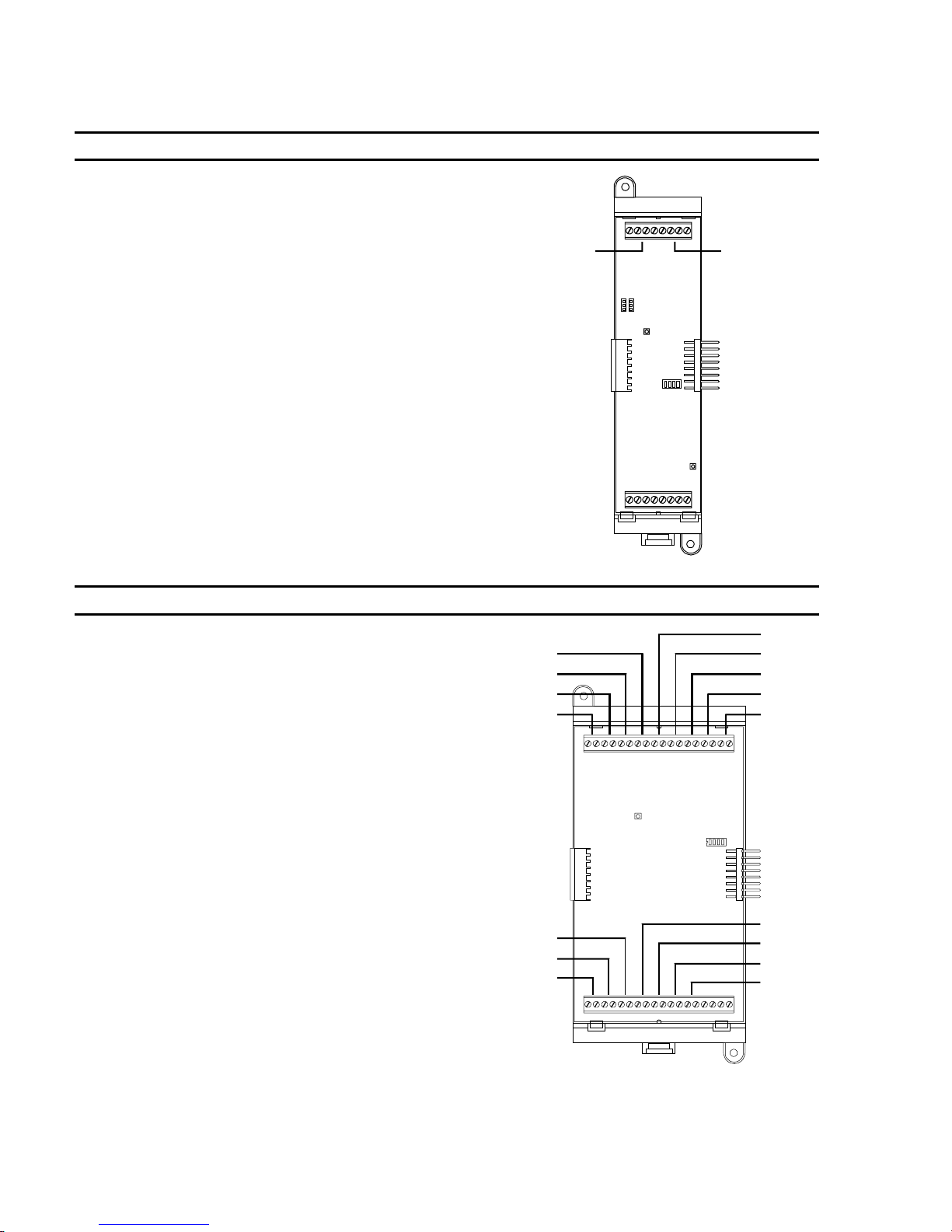
Programming instructions
Table 4-3: AutoLearn initial card configuration settings
Card Circuit Address Device type Edit? Diagram
SLIC NAC 1 270 Visible FPP/CU
NAC 2 271 Common Alarm
Output
FPP/CU
NAC 1 NAC 2
Card Circuit Address Device type Edit? Diagram
ZB16–4 Z1 001 Alarm FPP/CU
Z2 002 Alarm FPP/CU
Z3 003 Alarm FPP/CU
Z4 004 Alarm FPP/CU
Z4
Z3
Z2
Z1
Z5 005 Alarm FPP/CU
Z6 006 Alarm FPP/CU
Z7 007 Alarm FPP/CU
Z8 008 Alarm FPP/CU
Z9 009 Alarm FPP/CU
Z10 010 Alarm FPP/CU
Z11 011 Alarm FPP/CU
Z12 012 Alarm FPP/CU
Z13 013 Common Alarm
Output
Z14 014 Common Alarm
FPP/CU
FPP/CU
Z12
Z11
Z10
Output
Z15 015 Visible FPP/CU
Z16 016 Visible FPP/CU
Z5
Z6
Z7
Z8
Z9
Z13
Z14
Z15
Z16
4.10 QS4 Technical Reference Manual
Technical Manuals Online! - http://www.tech-man.com
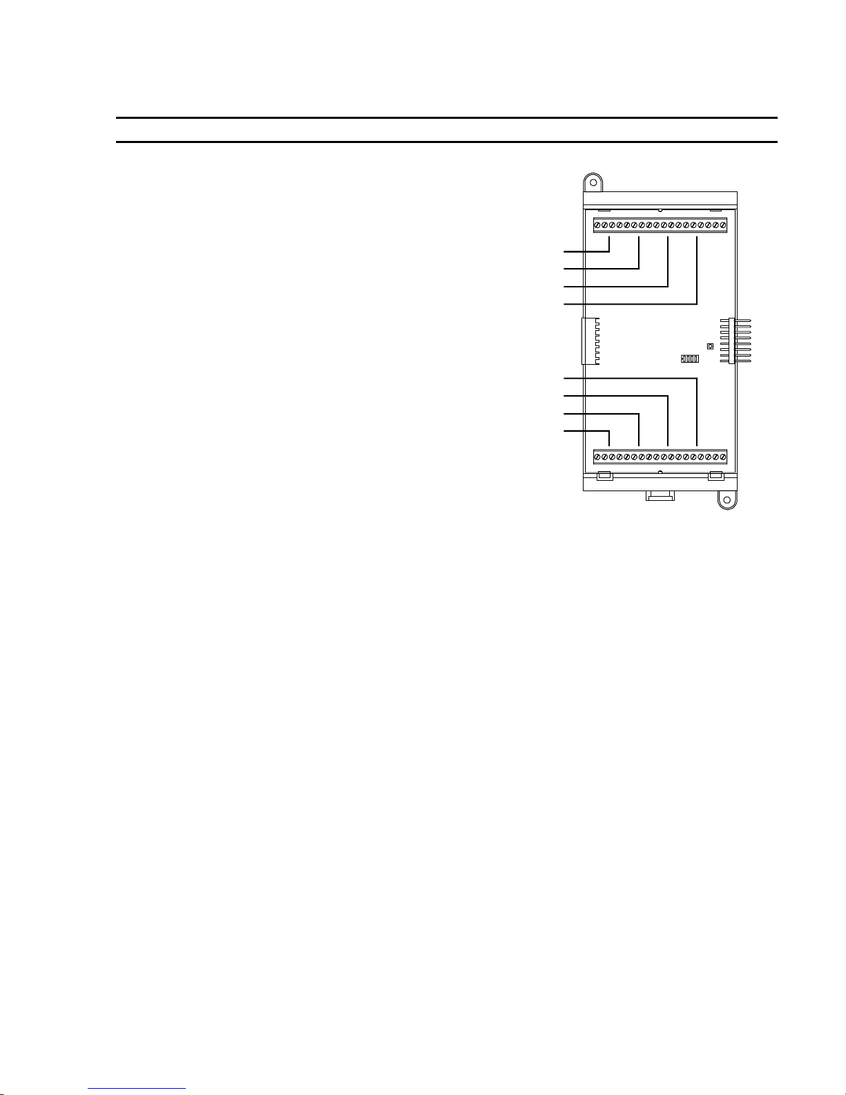
Programming instructions
Table 4-3: AutoLearn initial card configuration settings (cont.)
Card Circuit Address Setting Edit? Diagram
ZA8–2 Zone 1 001 Alarm FPP/CU
Zone 2 002 Alarm FPP/CU
Zone 3 003 Alarm FPP/CU
Zone 4 004
Zone 5 005 Alarm FPP/CU
Zone 6 006 Alarm FPP/CU
Zone 7 007 Alarm FPP/CU
Zone 8 008 Visible FPP/CU
Common Alarm
Output
FPP/CU
Zone 1
Zone 2
Zone 3
Zone 4
Zone 8
Zone 7
Zone 6
Zone 5
QS4 Technical Reference Manual 4.11
Technical Manuals Online! - http://www.tech-man.com

Programming instructions
Table 4-4: AutoLoop initial settings for SIGA devices
SIGA Device Personality Description Device Type Edit?
SIGA–IPHS, –PHS,
–PS, –IS
SIGA–HFS, HRS,
–IM
Single-stage pull
stations
Dual-stage pull
stations
SIGA–APS 03 Class B Active Non-Latching Monitor FPP/CU
SIGA–(M)CC1(S) 05 Riser selector Common Alarm
SIGA–(M)CC2 07 Dual riser selector Common Alarm
SIGA–(M)CR(R) 08 Dry contact Nonsupervised
SIGA–(M)CT1 01 Class B Alarm Latching Alarm FPP/CU
SIGA–(M)CT2 01 Class B Alarm Latching Alarm FPP/CU
SIGA–DTS 01 Class B Alarm Latching Alarm FPP/CU
SIGA–IO 31 Monitor Input/Output N.O. Monitor FPP/CU
SIGA–MAB 00 Class A Signal Output Monitor FPP/CU
SIGA–UM 00 Class A Signal Output Monitor FPP/CU
SIGA–MM1 03 Class B Active Non-Latching Monitor FPP/CU
SIGA–WTM 02 Class B Active Latching - Delayed Alarm FPP/CU
SIGA–(M)RM1 23 Riser monitor - 24 Vdc Monitor FPP/CU
none Smoke detector settings as follows:
Sensitivity: Least
Verification: None
Prealarm: None
none Heat detector settings not programmable Alarm FPP/CU
01 Class B Alarm Latching Pull FPP/CU
01 Class B Alarm Latching Monitor FPP/CU
01 Class B Alarm Latching Pull FPP/CU
03 Class B Active Non-Latching Monitor FPP/CU
01 Class B Alarm Latching Alarm FPP/CU
00 not used
00 not used
04 Class B Active Latching. Supervisory FPP/CU
Alarm FPP/CU
FPP/CU
Output
FPP/CU
Output
FPP/CU
Output
Note: If you use Signature devices from another system, the AutoLoop utility uses the attributes programmed from
the previous system as the initial settings for a general alarm system.
4.12 QS4 Technical Reference Manual
Technical Manuals Online! - http://www.tech-man.com

Customizing the system configuration
Programming instructions
You can customize the system configuration, if
your requirements exceed that of the general
alarm system created using the AutoLearn and
AutoLoop utilities.
Before you can make any changes to the system
programming, you must log onto the system to
start an editing session.
The control panel has a watchdog timer that kicks
you out of an editing session after a period of
inactivity. If this happens, you will have to log in
again to continue.
After you finish customizing the system
configuration, save your changes, and then test
the system. After everything checks out then Save
and Sync to copy the database to the remote
annunciators.
What is it you want to do This is how you do it
Make information about the installer available
on the CPU/Display
AutoLearn default: No text
WARNING: Entering Edit mode (choosing
Configure on the Program menu) disables the
control panel and leaves the premises unprotected
until you exit Edit mode.
To start an editing session:
1. Press Menu.
2. Choose Login then enter the password required
for Level 4 access.
3. Choose Program > Configure.
1. On the Configure menu, choose System > User
Labels.
2. Choose Facility Name, scan in the name of the
project, and then press Enter.
Set how long notification circuits must stay on
before pressing Alarm Silence can turn them
off or pressing Reset can reset the panel
AutoLearn default: None (no delay)
Set how long the panel must wait before
signaling an ac power failure
AutoLearn default: 0 (no delay)
3. Choose Inst Company, scan in the name of the
installing company, and then press Enter.
4. Choose Phone Number, scan in the telephone
number to call for service-related issues, and
then press Enter.
5. Choose Programmer, scan in the name of the
person that programmed the system, and then
press Enter.
6. Choose Exit.
1. On the Configure menu, choose System >
ALM/RST Inhib.
2. Select a time delay from the pick list then press
Enter.
1. On the Configure menu, choose System > AC
Power Dly.
2. Select a time delay from the pick list then press
Enter.
QS4 Technical Reference Manual 4.13
Technical Manuals Online! - http://www.tech-man.com

Programming instructions
What is it you want to do This is how you do it
Enter location message text for a circuit on a
ZB16–4 or ZA8–2 card
Change the device type of a circuit on a ZB16–
4 or ZA8–2 card
Change the device type of the NAC circuits on
the SLIC
AutoLearn defaults: NAC1 device type is Visible;
NAC 2 device type is Common Alarm Output
Common Alarm Output circuits turn on
automatically when an input signals an alarm
event. Visible and Audible output circuits must be
placed in an Output Group in order to turn them
on. The AutoLearn utility automatically places
Visible circuits in an Output Group
1. On the Configure menu, choose Card, and then
enter the card address number.
2. Choose Text Message, scan in the text, and
then press Enter.
3. Choose Exit.
WARNING: Changing the device type of an input
circuit to a device type for an output circuit
removes the circuit from all input logic groups.
Changing the device type of an output circuit to a
device type for an input circuit removes the output
circuit from all output groups.
1. On the Configure menu, choose Card, and then
enter the card address number.
2. Choose Device Type, select the device type
from the pick list, and then press Enter.
3. Choose Exit.
WARNING: Changing an output circuit from a
Common Alarm Output device type to an Audible
device type does not automatically place the
Audible circuit in an Output Group. You must add
the Audible Circuit to the Output Group manually
or the Audible circuit will not turn on.
1. On the Configure menu, choose Cards > Edit
then enter the card address number.
2. Choose Config Card.
4.14 QS4 Technical Reference Manual
Technical Manuals Online! - http://www.tech-man.com
3. Choose NAC 1 then choose the device type for
NAC 1.
4. Choose NAC 2 then choose the device type for
NAC 2.
5. Choose Exit > Save Edits, then wait while the
database is updated.

What is it you want to do This is how you do it
Programming instructions
Change the performance class of the Signature
loop wiring
AutoLearn default: Wiring is Class B.
Enter location message text for an automatic
detector
Change the Alarm Sensitivity setting of a
smoke detector
1. On the Configure menu, choose Cards > Edit
then enter the card address number.
2. Choose Config Card.
3. Choose Wiring Class then choose how the loop
is wired to the SLIC.
4. Choose Exit > Save Edits, then wait while the
database is updated.
1. On the Configure menu, choose Cards > Edit
and then enter the card address number of the
loop controller.
2. Choose Config Detect > Edit > Enter Serial #
and then scan or enter the detector's serial
number.
3. Choose Message then scan in the text that you
want sent when the detector signals an event.
4. Choose Exit > Save Edits.
WARNING: Selection of the appropriate detector
technology and sensitivity settings should result
from a careful analysis of the hazard,
environmental conditions, and expected results.
1. On the Configure menu, choose Cards > Edit
and then enter the card address number of the
loop controller.
2. Choose Config Detect > Edit > Enter Serial #
and then scan or enter the detector's serial
number.
3. Choose Sensitivity then choose the alarm
sensitivity setting you want the detector to use.
Refer to Table 4-5 and Table 4-6.
4. Choose Exit > Save Edits.
QS4 Technical Reference Manual 4.15
Technical Manuals Online! - http://www.tech-man.com

Programming instructions
What is it you want to do This is how you do it
Change the Alarm Verification setting of a
smoke detector
Change the Prealarm setting of a smoke
detector
1. On the Configure menu, choose Cards > Edit
and then enter the card address number of the
loop controller.
2. Choose Config Detect > Edit > Enter Serial #
and then scan or enter the detector's serial
number.
3. Choose Verification then choose the length of
the alarm verification period.
4. Choose Exit > Save Edits.
WARNING: Prealarm obscuration levels below
80% should not be used without full knowledge of
the possible consequences.
1. On the Configure menu, choose Cards > Edit
and then enter the card address number of the
loop controller.
2. Choose Config Detect > Edit > Enter Serial #
and then scan or enter the serial number of the
detector.
3. Choose Pre-Alarm then choose the warning
threshold setting you want the detector to use.
Refer to Table 4-5 and Table 4-6.
4. Choose Exit > Save Edits.
4.16 QS4 Technical Reference Manual
Technical Manuals Online! - http://www.tech-man.com
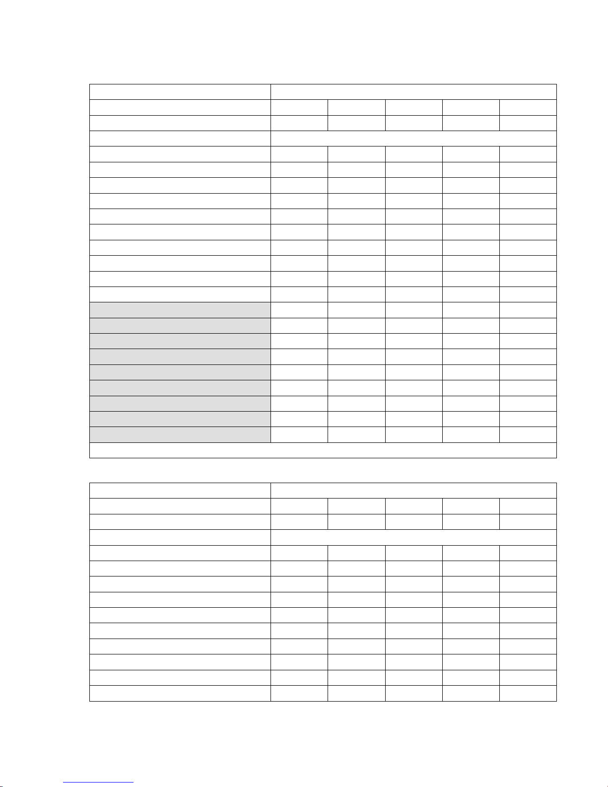
Table 4-5: %Obscuration levels for SIGA–IPHS, SIGA–PS, and SIGA–PHS
Alarm Obscuration Levels
Sensitivity Settings
%Obscuration
Prealarm Settings Prealarm Obscuration Levels
95% 0.95% 1.90% 2.38% 2.85% 3.33%
90% 0.90% 1.80% 2.25% 2.70% 3.15%
85% 0.85% 1.70% 2.13% 2.55% 2.98%
80% 0.80% 1.60% 2.00% 2.40% 2.80%
75% 0.75% 1.50% 1.88% 2.25% 2.63%
70% 0.70% 1.40% 1.75% 2.10% 2.45%
65% 0.65% 1.30% 1.63% 1.95% 2.28%
60% 0.60% 1.20% 1.50% 1.80% 2.10%
55% 0.55% 1.10% 1.38% 1.65% 1.93%
50% 0.50% 1.00% 1.25% 1.50% 1.75%
45% 0.45% 0.90% 1.13% 1.35% 1.58%
40% 0.40% 0.80% 1.00% 1.20% 1.40%
35% 0.35% 0.70% 0.88% 1.05% 1.23%
30% 0.30% 0.60% 0.75% 0.90% 1.05%
25% 0.25% 0.50% 0.13% 0.31% 0.88%
20% 0.20% 0.40% 0.50% 0.60% 0.70%
15% 0.15% 0.30% 0.38% 0.45% 0.53%
10% 0.10 0.20% 0.25% 0.30% 0.35%
5% 0.05 0.10% 0.13% 0.15% 0.18%
Note: Shaded prealarm settings not available for SIGA–IPHS
Most More Normal Less Least
1.00% 2.00% 2.50% 3.00% 3.50%
Programming instructions
Table 4-6: %Obscuration levels for SIGA–IS
Alarm Obscuration Levels
Sensitivity Settings
%Obscuration
Prealarm Settings Prealarm Obscuration Levels
95% 0.67% 0.95% 1.14% 1.33% 1.52%
90% 0.63% 0.90% 1.08% 1.26% 1.44%
85% 0.60% 0.85% 1.02% 1.19% 1.36%
80% 0.56% 0.80% 0.96% 1.12% 1.28%
75% 0.53% 0.75% 0.90% 1.05% 1.20%
70% 0.49% 0.70% 0.84% 0.98% 1.12%
65% 0.46% 0.65% 0.78% 0.91% 1.04%
60% 0.42% 0.60% 0.72% 0.84% 0.96%
55% 0.39% 0.55% 0.66% 0.77% 0.88%
50% 0.35% 0.50% 0.60% 0.70% 0.80%
Most More Normal Less Least
0.7% 1.00% 1.20% 1.40% 1.6%
QS4 Technical Reference Manual 4.17
Technical Manuals Online! - http://www.tech-man.com

Programming instructions
What is it you want to do This is how you do it
Enter location message text for a circuit on a
SIGA module
Change the device type for a circuit on a SIGA
module
Note: The device types shown in the pick lists vary
depending on the SIGA module. The device types
shown in the pick lists for the second address of a
dual-address module also vary depending on the
device type chosen for the first address.
1. On the Configure menu, choose Cards > Edit
and then enter the card address number of the
loop controller.
2. Choose Config Module > Edit > Enter Serial #
and then scan or enter the serial number of the
module.
3. For a single-address module or the first
address of a dual-address module, choose
Device 1.
— or —
For the second address of a dual-address
module, choose Device 2.
4. Choose Message, scan in the text, and then
press Enter.
5. Choose Exit.
1. On the Configure menu, choose Cards > Edit
and then enter the card address number of the
loop controller.
2. Choose Config Module > Edit > Enter Serial #
and then scan or enter the serial number of the
module.
3. For a single-address module or the first
address of a dual-address module, choose
Device 1.
— or —
For the second address of a dual-address
module, choose Device 2.
4. Choose Type, select a device type from the
pick list, and then press Enter.
5. Choose Exit.
4.18 QS4 Technical Reference Manual
Technical Manuals Online! - http://www.tech-man.com

What is it you want to do This is how you do it
Programming instructions
Change the personality code for a circuit on a
SIGA module
Note: The personality codes shown in the pick lists
vary depending on the SIGA module and the
chosen device type.
Enable the loop controller mapping function
AutoLearn default: Mapping disabled
1. On the Configure menu, choose Cards > Edit
and then enter the card address number of the
loop controller.
2. Choose Config Module > Edit > Enter Serial #
and then scan or enter the serial number of the
module.
3. For a single-address module or the first
address of a dual-address module, choose
Device 1.
— or —
For the second address of a dual-address
module, choose Device 2.
4. Choose Personality, select a personality code
from the pick list, and then press Enter.
5. Choose Exit.
1. Press Menu.
2. Log onto the panel as a Level 4 operator.
3. Choose Enable > Loop Mapping.
4. Enter the card number of the SLIC that
connects to the device you want to replace.
Wait until mapping finishes before continuing.
5. Choose Cards > Edit.
6. Enter the card number of the SLIC that
connects to the device you want to replace.
7. Choose Accept Map.
If actual and expected data for detectors and
modules are the same, press Enter.
8. Choose Exit > Exit > Save.
QS4 Technical Reference Manual 4.19
Technical Manuals Online! - http://www.tech-man.com

Programming instructions
Table 4-7: Device type descriptions
Alarm Device type assigned to IDC circuits that connect to automatic or a combination of automatic
and manual alarm-signal initiating devices. Alarm circuits signal Alarm Active events.
Alarm Output Device type assigned to IDC/NAC circuits that connect to notification appliances that you want
turned on automatically when the panel processes an alarm signal. Alarm Output circuits turn
off when you press Alarm Silence and turn on when you press Drill.
Audible
Heat Device type assigned to IDC circuits that connect to automatic alarm-signal initiating devices
Monitor Device type assigned to IDC circuits that connect to monitor-signal initiating devices that
Output Device type assigned to IDC/NAC circuits that supervise their output wiring for opens and
Pull Device type assigned to IDC circuits that connect to manually operated alarm-signal initiating
Supervisory
Tamper Device type assigned to IDC circuits that connect to supervisory-signal initiating devices that
Verified Smoke Device type assigned to IDC circuits that connect to automatic alarm-signal initiating devices
Visible
Water Flow
Device type assigned to IDC/NAC circuits that connect to audible notification appliances
(horns). Audible circuits turn off when you press Alarm Silence and turn on when you press
Drill.
that detect a rise in the surrounding temperature. Heat circuits signal Heat Alarm events.
monitor the operation of ancillary system functions. Monitor circuits signal Monitor events.
shorts. Output circuits do not turn off when you press Alarm Silence or turn on when you press
Drill.
devices. Pull circuits signal Pull Station events.
Device type assigned to IDC circuits that connect to supervisory-signal initiating devices that
detect abnormal conditions that could make the sprinkler system inoperative or ineffective.
Supervisory circuits signal Supervisory events.
detect when someone tampers with a component of the sprinkler system. Tamper circuits signal
Tamper events.
that use alarm verification. Verified Smoke circuits signal Alarm Verify events when the fire
condition is first detected then Alarm Active events after verifying the fire condition exists.
Device type assigned to IDC/NAC circuits that connect to visual notification appliances
(strobes). Visible circuits do not turn off when you press Alarm Silence or turn on when you
press Drill unless programmed to do so.
Device type assigned to IDC circuits that connect to alarm-signal initiating devices that detect
water flowing through the sprinkler system. Water Flow circuits signal Waterflow events.
4.20 QS4 Technical Reference Manual
Technical Manuals Online! - http://www.tech-man.com

Setting up an Output Group
Programming instructions
Before you begin
Adding a response that activates an
output circuit
Before you begin, you should complete an Output Group
Programming Worksheet (Figure 4-8) for each Output group.
Keep a copy for your records.
To set up an Output Group:
1. On the control panel, press Menu.
2. Choose Login then enter the password required for Level 4
access.
3. Choose Program > Configure > Output.
4. To program a new Output group, choose Add.
— or —
To edit an existing Output group, choose Edit, select the
group from the pick list, and then press Enter.
5. Add the responses.
6. After you finish entering the responses, you should review
them to make sure they are correct.
1. Choose Responses.
2. Choose Active or Trouble
Adding a response that activates a
delay
3. Choose Add > Relay, then enter the circuit address where
CC is the card number and DDD is the circuit number.
4. Choose the activation setting.
5. Choose Exit > Save Edits.
1. Choose Responses.
2. Choose Active or Trouble.
3. Choose Add > Delay.
4. Choose Delay Type, then choose when to initiate the delay
response.
5. Choose Delay Time, press Del four times, and then enter
how many seconds you want the delay to last.
6. Choose Exit > Save Edits.
QS4 Technical Reference Manual 4.21
Technical Manuals Online! - http://www.tech-man.com

Programming instructions
Adding a response that sends a
dialer string
Reviewing your responses
1. Choose Responses.
2. Choose Active or Trouble.
3. Choose Add > Dialer.
4. Select an account number from the pick list, and then press
Enter.
5. Choose Send On, select when to send the dialer string from
the pick list, and then press Enter.
6. Choose Priority, select the priority classification from the
pick list, and then press Enter.
7. Choose String, then enter the message you want sent.
8. Choose Exit > Save Edits.
1. Choose Review.
2. Choose Active to review the active responses.
— or —
Choose Trouble to review the trouble responses.
4.22 QS4 Technical Reference Manual
Technical Manuals Online! - http://www.tech-man.com

Programming instructions
Table 4-8: Response code definitions
Response Description
PppCccDddd 1234 This is what the panel display looks like when you review a response for an output
circuit.
P:pp C:cc D:ddd is the address of the of the output circuit (P = panel number, C =
card number, D = device number)
1 is the command direction (B = Both activation and restoration, A = Activation only,
R = Restoration only)
2 is the command (N = no operation, A = Activate, E = Enable, R = Restore, I =
Disable, D = Delay)
3 is the priority attribute (S = Set, A = Latch, L = Low, M = Medium, H = High)
4 is the command attribute (S = Set, R = Reset, W = 20 bpm, F = 120 bpm, T =
Temporal)
PppCccDddd 1234 This is what the panel display looks like when you review a response for an LED.
P:pp C:cc D:ddd is the address of the of the output circuit (P = panel number, C =
card number, D = device number)
1 is the command direction (B = Both activation and restoration, A = Activation only,
R = Restoration only)
2 is the command (N = no operation, A = Activate, E = Enable, R = Restore, I =
Disable, D = Delay)
3 is the priority attribute (S = Set, A = Latch, L = Low, M = Medium, H = High)
4 is the command attribute (S = Steady, R = Restore, W = Slow Blink, F = Fast
Blink)
Delay: ssss 1 This is what the panel display looks like when you review a response for delay.
ssss is the amount of delay in seconds
1 is the command direction (B = Both activation and restoration, A = Activation only,
R = Restoration only)
ACCT12QEEEGGPPP
— or —
ACCT12PP
This is what the panel display looks like when you review a response for dialer
string.
ACCT is the 4-digit subscriber account number (0000–9999)
1 is the priority attribute (L = Life Safety, P = Property, S = System Integrity)
2 s the command direction (B = Both activation and restoration, A = Activation only,
R = Restoration only)
For Contact ID dialer strings:
Q is the event qualifier (1 = activation event, 3 = restoration event)
EEE is the event code. See Table 4-9.
GGPPP is the point being reported
For 4/2 dialer strings:
PP is the point being reported (00–99)
QS4 Technical Reference Manual 4.23
Technical Manuals Online! - http://www.tech-man.com

Programming instructions
Table 4-9: Contact ID Event Codes
100 – Medical alarm
101 – Pendant transmitter
102 – Fail to report in
110– Fire Alarm
111 – Smoke
112 – Combustion
113 – Water Flow
114 – Heat
115 – Pull Station
116 – Duct
117 – Flame
118 – Near alarm
120 – Panic Alarm
121 – Duress
122 – Silent
123 – Audible
130 – Burglar Alarm
131 – Perimeter
132 – Interior
133 – 24 Hour
134 – Entry/Exit
135 – Day/Night
136 – Outdoor
137 – Tamper
138 – Near alarm
140 – General Alarm
141 – Polling loop open
142 – Polling loop short
143 – Expansion module failure
144 – Sensor tamper
145 – Expansion module failure
150 and 160 – 24-hour NonBurglary
151 – Gas detection
152 – Refrigeration
153 – Loss of heat
154 – Water leakage
155 – Foil break
156 – Day trouble
157 – Low bottled gas level
158 – High temperature
159 – Low temperature
161 – Loss of air flow
200 and 210 – Fire Supervisory
201 – Low water pressure
202 – Low CO
203 – Gate valve sensor
204 – Low water level
205 – Pump activated
206 – Pump failure
300 and 310 – System Troubles
301 – AC loss
302 – Low system battery
303 – RAM checksum bad
304 – ROM checksum bad
305 – System reset
306 – Panel program changed
307 – Self–test failure
308 – System shutdown
309 – Battery test failure
310 – Ground fault
320 – Sounder/Relay Trouble
321 – Bell 1
322 – Bell 2
323 – Alarm relay
324 – Trouble relay
325 – Reversing
330 and 340 – System Peripheral
Trouble
331 – Polling loop open
332 – Polling loop short
333 – Expansion module failure
334 – Repeater failure
335 – Local printer paper out
336 – Local printer failure
2
350 and 360 – Communication
Trouble
351 – Telco 1 fault
352 – Telco 2 fault
353 – Long range radio
354 – Fail to communicate
355 – Loss of radio supervision
356 – Loss of central polling
370 – Protection LoopTrouble
371 – Protection loop open
372 – Protection loop short
373 – Fire trouble
380 – Sensor Trouble
381 – Loss of supervisory (RF)
382 – Loss of supervisory (RPM)
383 – Sensor tamper
384 – RF transmitter low battery
400 – Open/Close
401 – Open/Close by user
402 – Group open/close
403 – Automatic open/close
404 – Late to open/close
405 – Deferred open/close
406 – Cancel
407 – Remote arm/disarm
408 – Quick arm
409 – Keyswitch open/close
410 – Remote Access
411 – Call request made
412 – Success – Download access
413 – Unsuccessful access
414 – System shutdown
415 – Dialer shutdown
4.24 QS4 Technical Reference Manual
Technical Manuals Online! - http://www.tech-man.com

Table 4-9: Contact ID Event Codes (cont.)
420 – Access Control
421 – Access denied
422 – Access report by user
441 – Stay arming
451 – Early opening/closing
452 – Late opening/closing
453 – Late to open
454 – Late to close
455 – Auto–arm failure
500 and 510 – System Disable
520 – Sounder/Relay Disable
521 – Bell 1 disable
522 – Bell 2 disable
523 – Alarm relay disable
524 – Trouble relay disable
525 – Reversing relay disable
530 and 540 – System Peripheral
Disable
550 and 560 – Communication
Disable
551 – Dialer disable
552 – Radio transmitter
570 – Disable Bypasses
570 – Zone bypass
571 – Fire zone bypass
572 – 24 Hour zone bypass
573 – Burglary zone bypass
574 – Group bypass
600 – Test/Misc.
601 – Manual trigger test
602 – Periodic test report
603 – Periodic RF transmission
604 – Fire test
605 – Status report to follow
606 – Listen–in follow
607 – Walk Test mode
621 – Event Log reset
622 – Event Log 50% full
623 – Event Log 90% full
624 – Event log overflow
625 – Time/Date reset
626 – Time/Date inaccurate
627 – Program mode entry
628 – Program mode exit
631 – Exception schedule change
Programming instructions
QS4 Technical Reference Manual 4.25
Technical Manuals Online! - http://www.tech-man.com

Programming instructions
Setting up a Zone
Before you begin
Configure the Zone
Before you begin, you should complete a Zone Programming
Worksheet (Figure 4-9) for each Zone. Keep a copy for your
records. You will also need to refer to the Output Group
programming worksheets.
To set up a Zone:
1. On the control panel, press Menu.
2. Choose Login then enter the password required for Level 4
access.
3. Choose Program > Configure > Zone.
4. To program a new Zone, choose Add, and then choose a
zone type (Alarm, Supervisory, or Monitor).
— or —
Choose Edit, select an existing zone from the pick list, and
then press Enter.
1. Choose Message, scan in the message text, and then
press Enter.
2. Choose Members, then for each device that comprises the
Zone:
Choose Device Address, then enter the member's device
number from the worksheet
— or —
Choose Enter Serial#, scan in or enter the member's serial
number.
3. Choose Review to verify which devices you added to the
Zone. If you added any devices in error, delete them.
4. Choose Output Group > Add, then select the Output group
from the pick list that contains the responses you want
activated, and then press Enter.
Repeat for each Output group you want to add.
5. Choose Review to verify which Output groups you added to
the Zone. If you added any Output groups in error, remove
them.
6 For coded systems, choose Coding, and then enter the
Zone Code.
4.26 QS4 Technical Reference Manual
Technical Manuals Online! - http://www.tech-man.com

Programming instructions
Job Name: Page
of
Panel: Card: 14
# of CMS receivers: ¨ 1 ¨ 2
CMS phone numbers: Receiver 1: #1) Receiver 1: #2)
Receiver 2: #1) Receiver 2: #2)
Retry Count: ¨ 5 ¨ 6 ¨ 7 ¨ 8 ¨ 9 ¨ 10
Account Number:
Test strings: Panel normal: Panel off-normal:
Time: CMS receiver to dial: ¨ 1 ¨ 2
Account Number: Format: ¨ 4/2 ¨ Contact ID
Test strings: Panel normal: Panel off-normal:
Time: CMS receiver to dial: ¨ 1 ¨ 2
Account Number: Format: ¨ 4/2 ¨ Contact ID
Test strings: Panel normal: Panel off-normal:
Time: CMS receiver to dial: ¨ 1 ¨ 2
Format: ¨ 4/2 ¨ Contact ID
Account Number: Format: ¨ 4/2 ¨ Contact ID
Test strings: Panel normal: Panel off-normal:
Time: CMS receiver to dial: ¨ 1 ¨ 2
Account Number: Format: ¨ 4/2 ¨ Contact ID
Test strings: Panel normal: Panel off-normal:
Time: CMS receiver to dial: ¨ 1 ¨ 2
Account Number: Format: ¨ 4/2 ¨ Contact ID
Test strings: Panel normal: Panel off-normal:
Time: CMS receiver to dial: ¨ 1 ¨ 2
Account Number: Format: ¨ 4/2 ¨ Contact ID
Test strings: Panel normal: Panel off-normal:
Time: CMS receiver to dial: ¨ 1 ¨ 2
Account Number: Format: ¨ 4/2 ¨ Contact ID
Test strings: Panel normal: Panel off-normal:
Time: CMS receiver to dial: ¨ 1 ¨ 2
Figure 4-1: DLD Programming Worksheet (sheet 1 of 2)
QS4 Technical Reference Manual 4.27
Technical Manuals Online! - http://www.tech-man.com

Programming instructions
Job Name: Page
Panel: Card: 14
Default Alarm Message: Account Number:
Active Message:
Restore Message:
Default Trouble Message: Account Number:
Active Message:
Restore Message:
Default Supervisory Message: Account Number:
Active Message:
Restore Message:
Figure 4-1 DLD Programming Worksheet (sheet 1 of 2)
of
4.28 QS4 Technical Reference Manual
Technical Manuals Online! - http://www.tech-man.com

Programming instructions
Job Name: Page
Panel: Card:
001 Device Type:
Text Message: 1)
2)
002 Device Type:
Text Message: 1)
2)
003 Device Type:
Text Message: 1)
2)
004 Device Type:
Text Message: 1)
2)
005 Device Type:
Text Message: 1)
2)
006 Device Type:
Text Message: 1)
2)
IDC 001
IDC 002
IDC 003
IDC/NAC 004
IDC/NAC 008
IDC 007
IDC 006
IDC 005
Defaults: Alarm for IDC 001 – 003 and IDC 005 – 007,
Common Alarm Output for IDC/NAC 004, Visual for
IDC/NAC 008
of
007 Device Type:
Text Message: 1)
2)
008 Device Type:
Text Message: 1)
2)
Figure 4-2: ZA8–2 Programming Worksheet
QS4 Technical Reference Manual 4.29
Technical Manuals Online! - http://www.tech-man.com

Programming instructions
Job Name: Page
Panel: Card:
001 Device Type:
Text Message: 1)
2)
002 Device Type:
Text Message: 1)
2)
003 Device Type:
Text Message: 1)
2)
004 Device Type:
Text Message: 1)
2)
005 Device Type:
Text Message: 1)
2)
006 Device Type:
Text Message: 1)
2)
007 Device Type:
Text Message: 1)
2)
008 Device Type:
Text Message: 1)
2)
009 Device Type:
Text Message: 1)
2)
010 Device Type:
Text Message: 1)
2)
011 Device Type:
Text Message: 1)
2)
IDC 001
IDC 002
IDC 003
IDC 004
IDC 012
IDC 011
IDC 010
Defaults: Alarm for IDC 001–012, Common Alarm
Output for IDC/NAC 013–014, Visual for IDC/NAC 015–
016
012 Device Type:
Text Message: 1)
2)
013 Device Type:
Text Message: 1)
2)
014 Device Type:
Text Message: 1)
2)
015 Device Type:
Text Message: 1)
2)
016 Device Type:
Text Message: 1)
2)
IDC 005
IDC 006
IDC 007
IDC 008
IDC 009
IDC/NAC 013
IDC/NAC 014
IDC/NAC 015
IDC/NAC 016
of
Figure 4-3: ZB16–4 Programming Worksheet
4.30 QS4 Technical Reference Manual
Technical Manuals Online! - http://www.tech-man.com
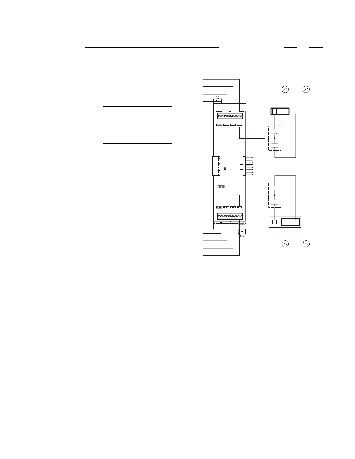
Programming instructions
Job Name: Page
Panel: Card:
001 ¨ NC (normally-closed)
¨ NO (normally-open)
Device type:
004
003
002
001
004+ 004–
JP4
002 ¨ NC (normally-closed)
¨ NO (normally-open)
Device type:
NC
NO
003 ¨ NC (normally-closed)
¨ NO (normally-open)
Device type:
NC
004 ¨ NC (normally-closed)
¨ NO (normally-open)
NO
of
Device type:
005 ¨ NC (normally-closed)
¨ NO (normally-open)
Device type:
006 ¨ NC (normally-closed)
¨ NO (normally-open)
Device type:
007 ¨ NC (normally-closed)
¨ NO (normally-open)
Device type:
008 ¨ NC (normally-closed)
¨ NO (normally-open)
Device type:
005
006
007
008
JP8
008+ 008–
Figure 4-4: ZA8–2 Programming Worksheet
QS4 Technical Reference Manual 4.31
Technical Manuals Online! - http://www.tech-man.com

Programming instructions
Job Name: Page
Panel:
Card:
NAC 1 device type: ¨ Audible ¨ Visible NAC 2 device type: ¨ Audible ¨ Visible
Wiring class: ¨ Class A ¨ Class B
Number of detector addresses used on loop:
Number of module addresses used on loop:
Card:
NAC 1 device type: ¨ Audible ¨ Visible NAC 2 device type: ¨ Audible ¨ Visible
Wiring class: ¨ Class A ¨ Class B
Number of detector addresses used on loop:
Number of module addresses used on loop:
Card:
NAC 1 device type: ¨ Audible ¨ Visible NAC 2 device type: ¨ Audible ¨ Visible
of
Wiring class: ¨ Class A ¨ Class B
Number of detector addresses used on loop:
Number of module addresses used on loop:
Card:
NAC 1 device type: ¨ Audible ¨ Visible NAC 2 device type: ¨ Audible ¨ Visible
Wiring class: ¨ Class A ¨ Class B
Number of detector addresses used on loop:
Number of module addresses used on loop:
Figure 4-5: SLIC Programming Worksheet
4.32 QS4 Technical Reference Manual
Technical Manuals Online! - http://www.tech-man.com

Programming instructions
Job Name: Page
Panel: Card:
Model: S/N Device:
Sensitivity: ¨ Most ¨ More ¨ Normal ¨ Less ¨ Least
Verification: ¨ None ¨ 12 s ¨ 24 s ¨ 36 s ¨ 60 s
Pre-Alarm: ¨ None ¨ 20% ¨ 40% ¨ 60% ¨ 80%
Base type: ¨ Standard ¨ Relay ¨ Isolator
Message: 1) 2)
Model: S/N Device:
Sensitivity: ¨ Most ¨ More ¨ Normal ¨ Less ¨ Least
Verification: ¨ None ¨ 12 s ¨ 24 s ¨ 36 s ¨ 60 s
Pre-Alarm: ¨ None ¨ 20% ¨ 40% ¨ 60% ¨ 80%
Base type: ¨ Standard ¨ Relay ¨ Isolator
of
Message: 1) 2)
Model: S/N Device:
Sensitivity: ¨ Most ¨ More ¨ Normal ¨ Less ¨ Least
Verification: ¨ None ¨ 12 s ¨ 24 s ¨ 36 s ¨ 60 s
Pre-Alarm: ¨ None ¨ 20% ¨ 40% ¨ 60% ¨ 80%
Base type: ¨ Standard ¨ Relay ¨ Isolator
Message: 1) 2)
Model: S/N Device:
Sensitivity: ¨ Most ¨ More ¨ Normal ¨ Less ¨ Least
Verification: ¨ None ¨ 12 s ¨ 24 s ¨ 36 s ¨ 60 s
Pre-Alarm: ¨ None ¨ 20% ¨ 40% ¨ 60% ¨ 80%
Base type: ¨ Standard ¨ Relay ¨ Isolator
Message: 1) 2)
Figure 4-6: Signature Detector Programming Worksheet
QS4 Technical Reference Manual 4.33
Technical Manuals Online! - http://www.tech-man.com

Programming instructions
Job Name: Page
of
Panel: Card:
Model: S/N Device: 1st) 2nd)
Device #1 Device #2
Device Type: Device Type:
Personality: Personality:
Message: 1) Message: 1)
2) 2)
Model: S/N Device: 1st) 2nd)
Device #1 Device #2
Device Type: Device Type:
Personality: Personality:
Message: 1) Message: 1)
2) 2)
Model: S/N Device: 1st) 2nd)
Device #1 Device #2
Device Type: Device Type:
Personality: Personality:
Message: 1) Message: 1)
2) 2)
Model: S/N Device: 1st) 2nd)
Device #1 Device #2
Device Type: Device Type:
Personality: Personality:
Message: 1) Message: 1)
2) 2)
Figure 4-7: Signature Module Programming Worksheet
4.34 QS4 Technical Reference Manual
Technical Manuals Online! - http://www.tech-man.com

Programming instructions
Job Name: Page
Panel: Output Group:
Response: __ __ __ Type: ¨ Active ¨ Trouble
¨ Relay Device: __ __ __ __ __ ¨ On ¨ 20 bpm ¨ 120 bpm ¨ Temporal
¨ Delay Delay Type: ¨ Act and Restoration ¨ Activation ¨ Restoration Time: __ __ __ __s
¨ Dialer Account No.: __ __ __ __ Send On: ¨ Activation ¨ Restoration
Priority: ¨ Life Safety ¨ Property ¨ System Integrity
String: (CID) __ __ __ __ __ __ __ __ __ (4/2) __ __
Response: __ __ __ Type: ¨ Active ¨ Trouble
¨ Relay Device: __ __ __ __ __ ¨ On ¨ 20 bpm ¨ 120 bpm ¨ Temporal
¨ Delay Delay Type: ¨ Act and Restoration ¨ Activation ¨ Restoration Time: __ __ __ __s
¨ Dialer Account No.: __ __ __ __ Send On: ¨ Activation ¨ Restoration
Priority: ¨ Life Safety ¨ Property ¨ System Integrity
of
String: (CID) __ __ __ __ __ __ __ __ __ (4/2) __ __
Response: __ __ __ Type: ¨ Active ¨ Trouble
¨ Relay Device: __ __ __ __ __ ¨ On ¨ 20 bpm ¨ 120 bpm ¨ Temporal
¨ Delay Delay Type: ¨ Act and Restoration ¨ Activation ¨ Restoration Time: __ __ __ __s
¨ Dialer Account No.: __ __ __ __ Send On: ¨ Activation ¨ Restoration
Priority: ¨ Life Safety ¨ Property ¨ System Integrity
String: (CID) __ __ __ __ __ __ __ __ __ (4/2) __ __
Figure 4-8: Output Group Programming Worksheet
QS4 Technical Reference Manual 4.35
Technical Manuals Online! - http://www.tech-man.com

Programming instructions
Job Name: Page
Panel: Zone:
Zone Type: ¨ Alarm ¨ Supervisory ¨ Monitor
Zone Code:
Message: 1)
Zone Members (32 max):
2)
of
Output groups (6 max):
Figure 4-9: Zone Programming Worksheet
4.36 QS4 Technical Reference Manual
Technical Manuals Online! - http://www.tech-man.com

Chapter 5
Standard applications
Summary
This chapter provides simplified wiring schematics for standard
applications.
Content
Notification appliance circuits • 5.2
Initiating device circuits • 5.5
Coded alarm signaling • 5.8
Remote station protective signaling system • 5.10
Auxiliary protective signaling • 5.12
QS4 Technical Reference Manual 5.1
Technical Manuals Online! - http://www.tech-man.com
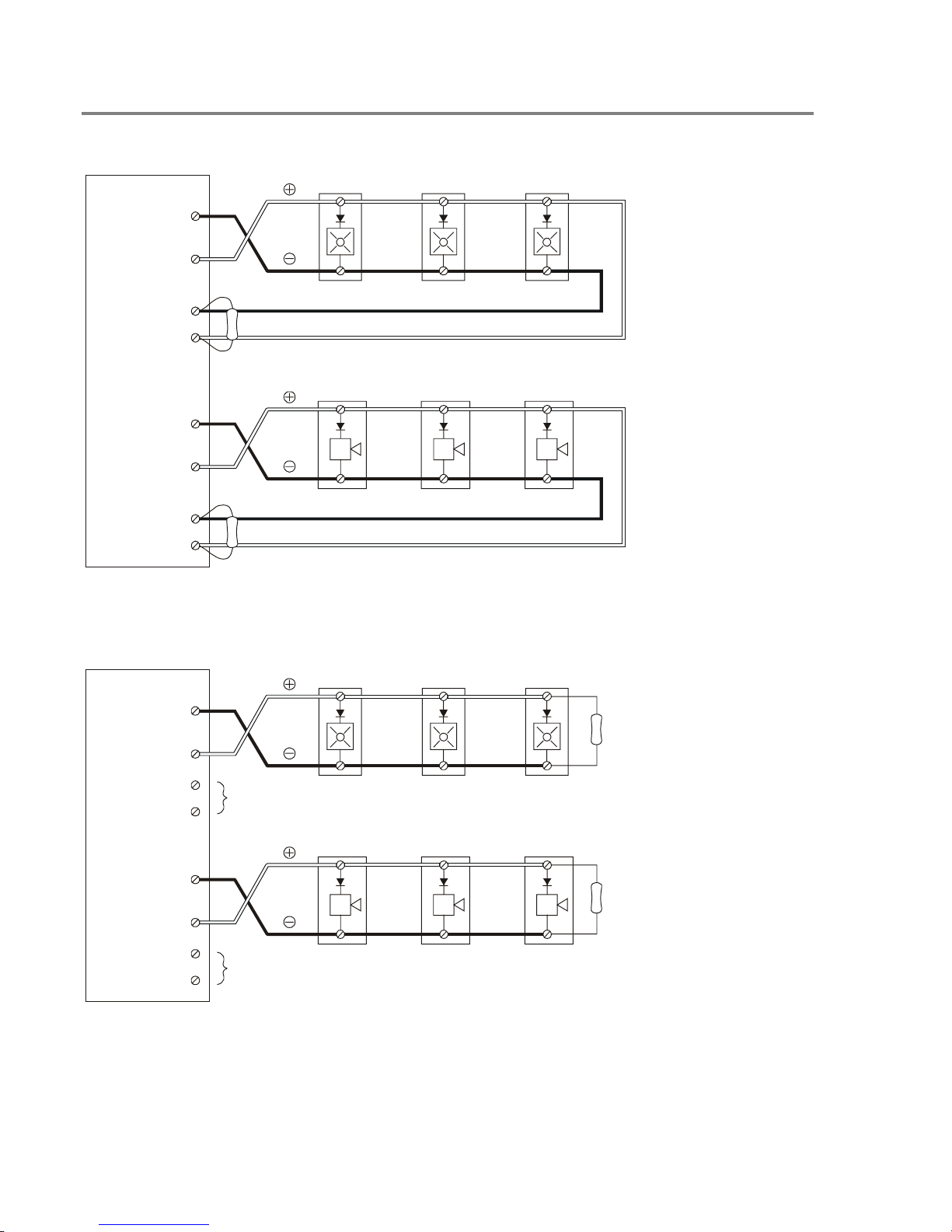
Standard applications
R
Notification appliance circuits
SLIC
NAC1 B+
NAC1 B–
NAC1 A+
NAC1 A–
UL/ULC LISTED
10 K EOLR
NAC2 B+
NAC2 B–
NAC2 A+
NAC2 A–
UL/ULC LISTED
10 K EOL
Typical Class A NAC circuits
Note: The plus and
minus symbols
indicate signal
polarity when the
NAC circuit is turned
on.
Ω
Ω
SLIC
NAC1 B+
NAC1 B–
NAC1 A+
NAC1 A–
NAC2 B+
NAC2 B–
NAC2 A+
NAC2 A–
NOT USED
NOT USED
Typical Class B NAC circuits
UL/ULC LISTED
Ω
10 K EOLR
UL/ULC LISTED
10 K EOLR
Ω
Note: The plus and
minus symbols
indicate signal
polarity when the
NAC circuit is turned
on.
5.2 QS4 Technical Reference Manual
Technical Manuals Online! - http://www.tech-man.com

10 9
SIGA–CC1
Standard applications
UL/ULC LISTED
Ω
47 K EOLR
SIGA–RM1
PS6
SLIC
LOOP B+
LOOP B–
LOOP A+
LOOP A–
12435687
AUX(n)
COM
TO DATA IN TERMINALS
ON NEXT DEVICE
TO DATA OUT TERMINALS
ON LAST DEVICE (CLASS A ONLY)
12435687
Note: The plus and minus symbols indicate signal polarity when the NAC circuit is turned on.
Typical NAC riser wiring
QS4 Technical Reference Manual 5.3
Technical Manuals Online! - http://www.tech-man.com
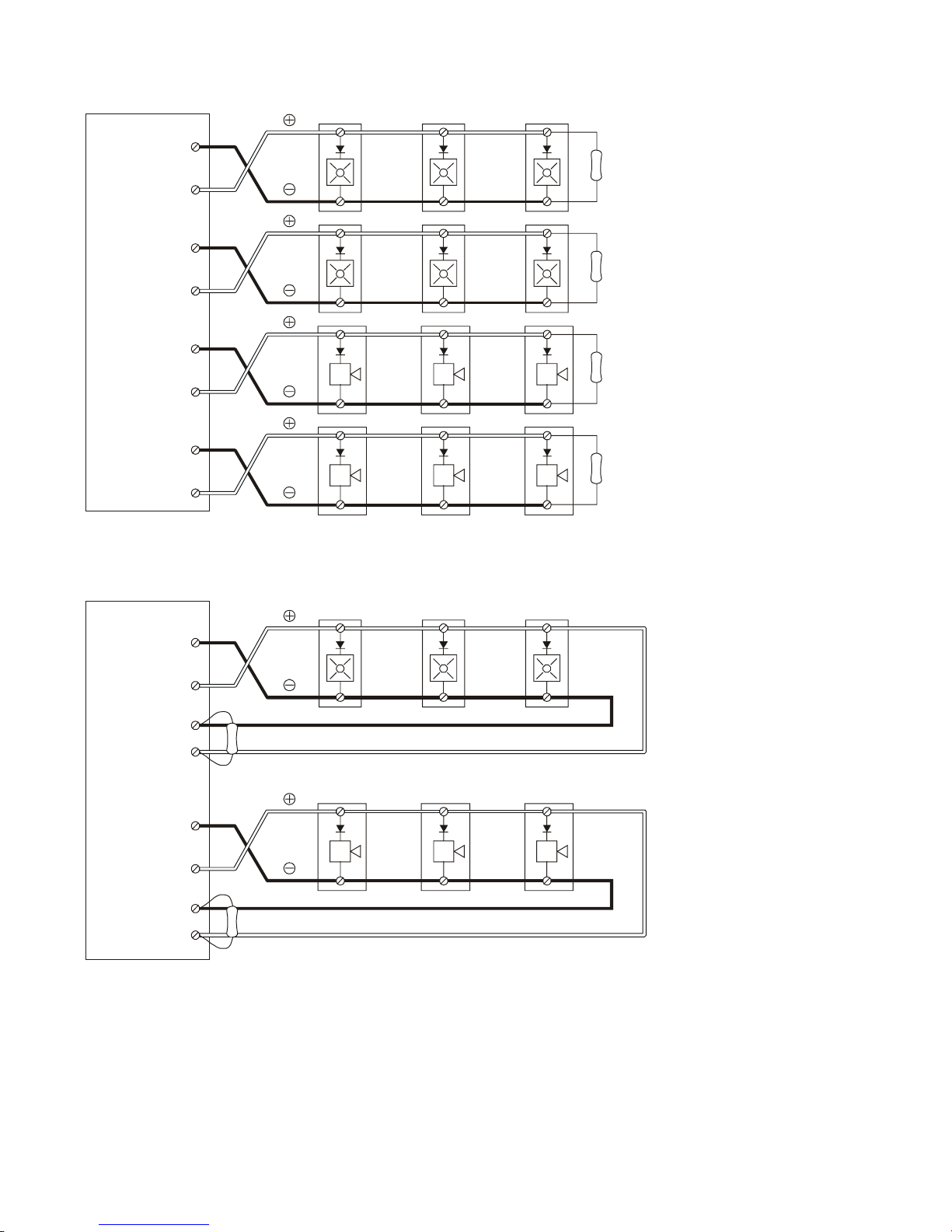
Standard applications
R
ZB16–4
Z13+
Z13–
UL/ULC LISTED
10 K EOLR
Ω
Z14+
Z14–
Z15+
Z15–
Z16+
Z16–
Typical Class B NAC circuits
ZA8–2
ZONE 4 B+
ZONE 4 B–
UL/ULC LISTED
10 K EOLR
Ω
UL/ULC LISTED
10 K EOLR
Ω
UL/ULC LISTED
10 K EOLR
Ω
ZONE 4 A+
ZONE 4 A–
NAC1 B+
NAC1 B–
NAC1 A+
NAC1 A–
UL/ULC LISTED
10 K EOLR
Ω
UL/ULC LISTED
10 K EOL
Ω
Typical Class A NAC circuit
5.4 QS4 Technical Reference Manual
Technical Manuals Online! - http://www.tech-man.com
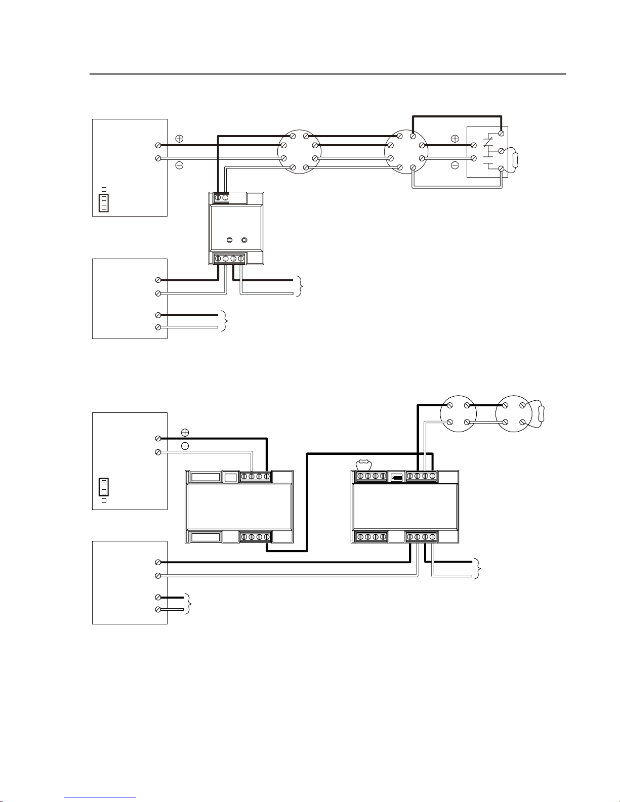
Initiating device circuits
PS6
24VDC+
24VDC–
JP2
ACC PWR
SMK PWR
SLIC
LOOP B+
LOOP B–
87
SIGA–CT1
4321
TO DATA IN TERMINALS
ON NEXT DEVICE
Standard applications
UL/ULC LISTED
EOL RELAY
UL/ULC LISTED
47 K EOLR
Ω
LOOP A+
LOOP A–
TO DATA OUT TERMINALS
ON LAST DEVICE (CLASS A ONLY)
Typical four-wire smoke detector circuit
PS6
24VDC+
24VDC–
JP2
ACC PWR
SLIC
SMK PWR
LOOP B+
LOOP B–
LOOP A+
LOOP A–
TO DATA OUT TERMINALS
ON LAST DEVICE (CLASS A ONLY)
2–SMK
UL/ULC LISTED
Ω
22 K EOLR
3-2-1
SIGA–UM
UL/ULC LISTED
Ω
15 K EOLR
91011121314
12345678
DATA IN TERMINALS
TO
ON NEXT DEVICE
Typical Class B two-wire smoke detector circuit
QS4 Technical Reference Manual 5.5
Technical Manuals Online! - http://www.tech-man.com
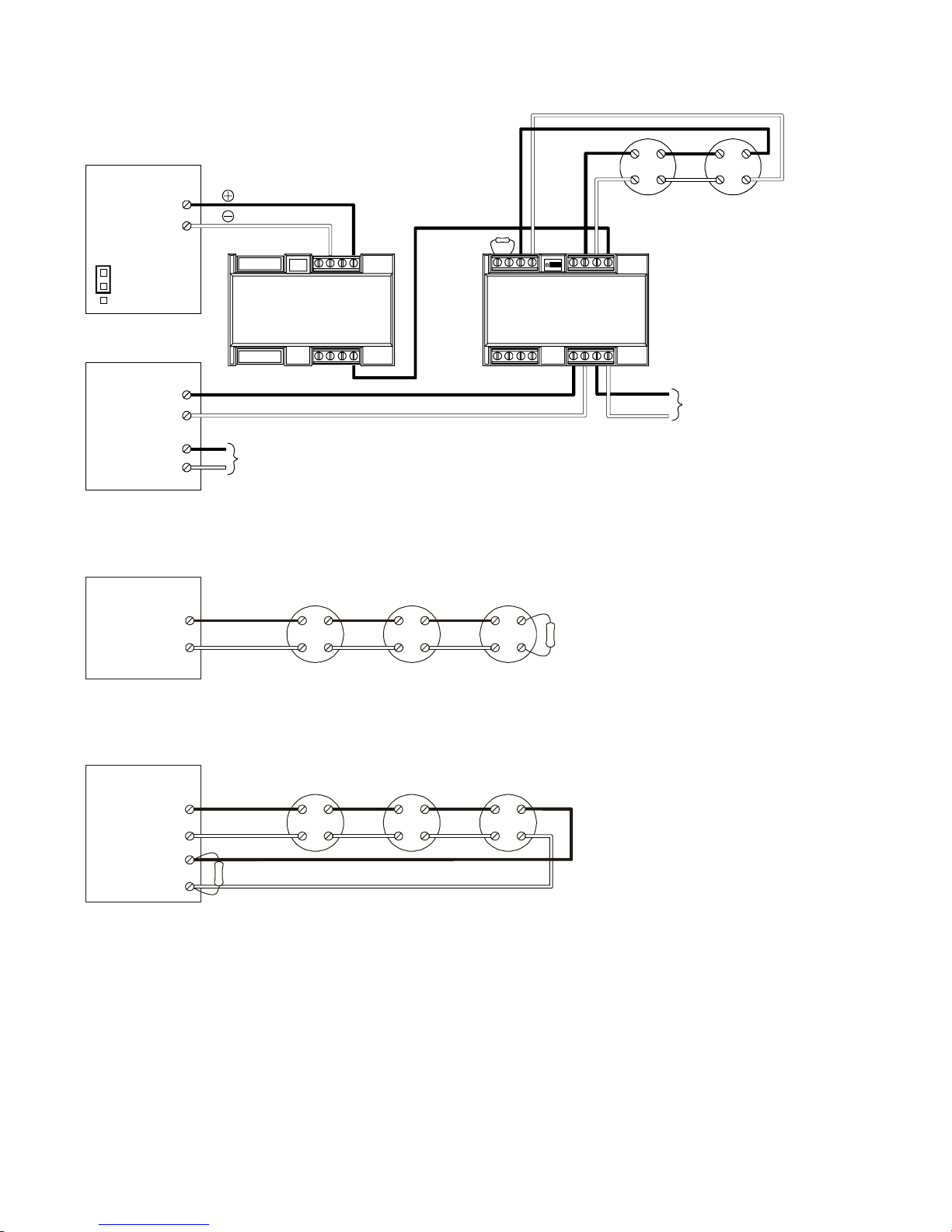
Standard applications
R
PS6
24VDC+
24VDC–
JP2
ACC PWR
SMK PWR
2–SMK
UL/ULC LISTED
Ω
22 K EOLR
3-2-1
SIGA–UM
91011121314
12345678
SLIC
LOOP B+
LOOP B–
LOOP A+
LOOP A–
TO DATA OUT TERMINALS
ON LAST DEVICE (CLASS A ONLY)
Typical Class A two-wire smoke detector circuit
ZB16–4
Z(n)+
Z(n)–
Typical Conventional Class B IDC circuit
ZA8–2
ZONE (n) B+
ZONE (n) B–
ZONE (n) B+
ZONE (n) B–
UL/ULC LISTED
Ω
4.7 K EOL
UL/ULC LISTED
4.7 K EOLR
Ω
DATA IN TERMINALS
TO
ON NEXT DEVICE
Typical Conventional Class A IDC circuit
5.6 QS4 Technical Reference Manual
Technical Manuals Online! - http://www.tech-man.com
 Loading...