

Page 1
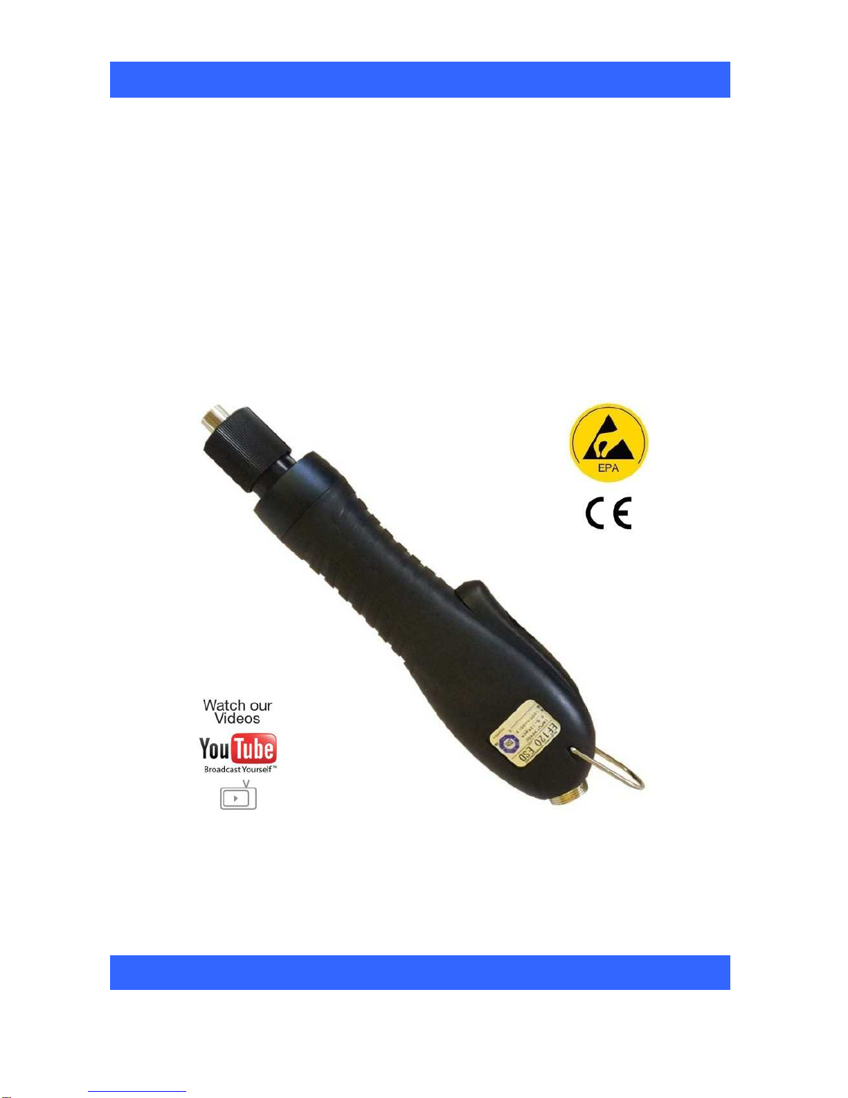
Electric Torque
Screwdriver
EF 120
Operators Manual
EF 120
Instruction part Number P32230 Issue 4
Page 2

Screwdriver/Controller Setup:
1. Attach power lead to the Screwdriver. Make sure notch in plug lines up with the notch on the socket.
Tighten knurled ground ring. Attach power lead to the STC 30+ Controller. Make sure notch in plug lines
up with the notch on the socket. Tighten knurled ring.
2. To insert a driver bit, retract the driver bit chuck. Insert the driver bit and release the retracted chuck
collar. To avoid damaging fasteners, make sure the correct driver bit is suitable for the head of the
fastener.
3. The Torque setting is determined by the tension of the coil spring housed in the torque adjustment
sleeve. See charts below to determine the appropriate torque adjustment setting.
4. Rotate the torque adjustment collar to set the required Torque. Turn clockwise to increase torque and
counter clockwise to decrease torque.
Note:
The scale adjacent to the Torque Adjustment Collar is a reference guide. The torque output from the
driver can change depending on various fastening factors like friction, type of joint, and the type material
being used like a washer.
5. Attach the power lead to the STC 30+ Controller. Plug in and check the power indicator illuminates. If it
does not, check fuse in the Controller.
The STC 30+ Controller - Features a HIGH & LOW speed button. Select the appropriate speed for your
application.
6. Operate driver and check for proper rotation. FOR-clockwise, REV-counterclockwise.
7. To apply torque, rotate the adjustment collar to the required setting on the adjustment scale. Squeeze
the lever. The driver will automatically stop when the preset torque has been reached.
8. To remove the screw, operate the Forward/Reverse switch to the reverse position.
How To Replace The Carbon Brushes:
WARNING: When replacing the carbon brushes, detach the power lead from the driver body or unplug
the transformer from the power supply.
1. The carbon brush piece is 1/3" long when new. Change the pair when they are worn to about half the
original length.
2. Insert a flat bladed screwdriver into the slot of the carbon brush cap and unscrew the cap.
3. Replace the worn brushes with a new pair. The contact surface of the brush is concave. Insert the brush
so that the concave end properly aligns with rounded surface of motor comutator.
Page 3
Care:
1. The EF 120 screwdriver is a precision torque control instrument and should be handled with care at all
times.
2. Only use the STC 30+ Controller listed with your EF 120 driver.
(If you have any questions regarding the appropriate controller set-up, contact the Torqueleader
Customer Service Department on 01483 894476).
3. Operate under safe conditions. Do not place in operation where such objects as hair, strings, clothing,
etc. can become tangled in the rotating driver bit.
4. Keep away from moisture. Never use in high humidity, or damp environments.
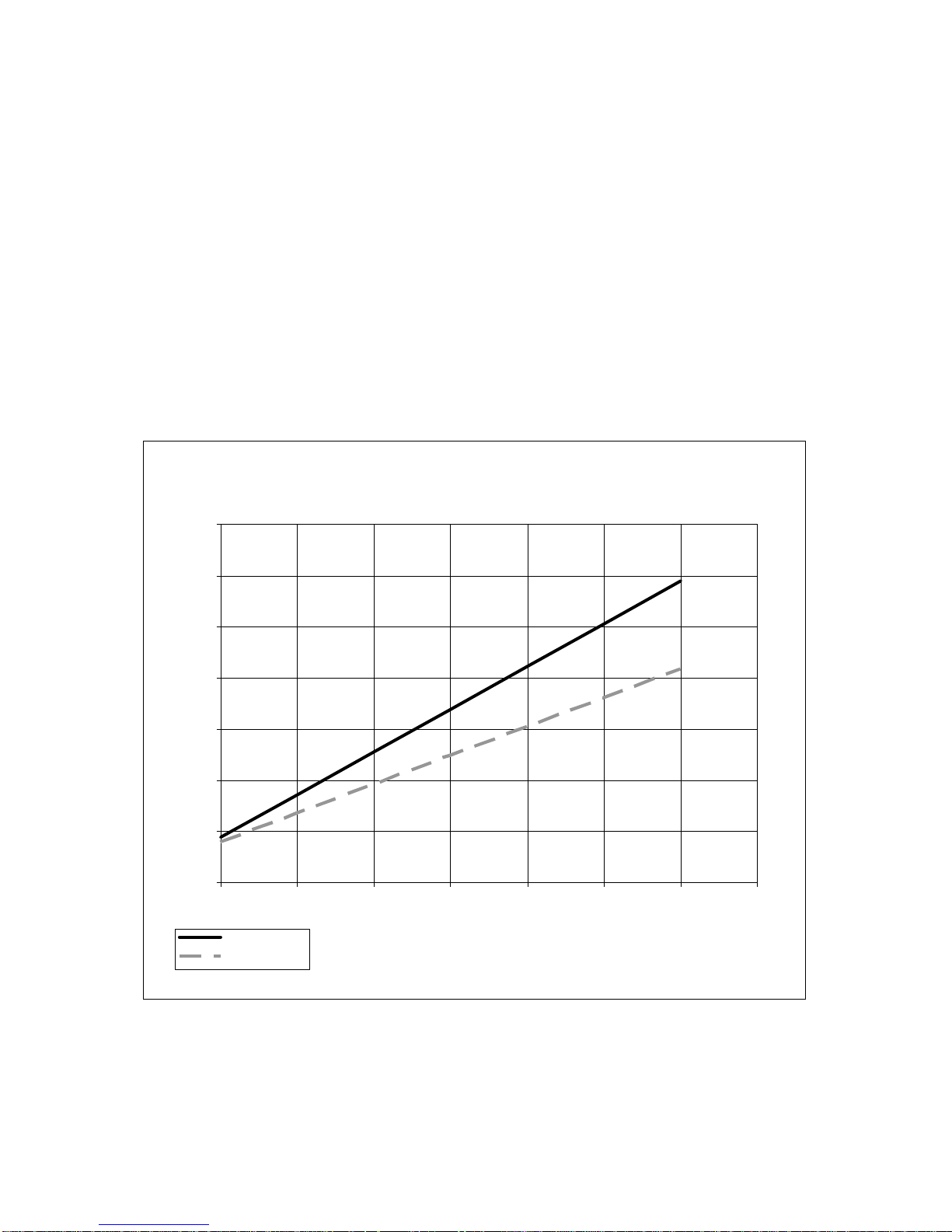
Torque Reference Graph:
This graph should be used as a guide for setting the Torque Driver. The Driver has a torque scale on the
Torque Adjustment Collar showing reference numbers. These numbers determine the approximate torque
setting for the spring type being used.
Two springs are supplied with the EF 120 – Black and Silver
EF 120 Screwdriver
140
120
100
80
60
Torque cNm
40
20
0
0 1 2 3 4 5 6 7
BLACK (dia. 2.0)
SILVER (dia. 1.8)
Scale
NOTE:. It may be necessary to change the spring in order to achieve the desired torque setting.
The springs can be changed by rotating the adjustment collar in the anti-clockwise direction until the collar
can be removed. Access to the spring is then gained by removal of the locating ring. Care must be taken
when refitting the locating ring by ensuring the rings pegs are correctly aligned with the grooves in the driver
spindle.
Page 4

Part Description
Inspection Period
Replacement
Accessory:
The torque cover protects the EF-Series from incidental or operator tampering of the torque setting.
Torque Cover EF 120
Protects the EF 120 from accidental adjustment or operator tampering of torque setting.
Order Code: 090210
Testing Power Tools:
1. Application Method: Use a Torque Analyser in “Peak Mode” with a Rotary Transducer between the
power tool and the application. This is the best way to test since you are using the actual joint as the test
station. You will see the actual torque applied to the fastener. Caution: Variances in tool performance
may occur due to the addition of the rotary transducer.
Caution: Variances in tool performance may occur do to the addition of the rotary transducer.
2. Simulated Method: Always use a quality joint rate simulator (run down adapter) with a torque analyzer
when testing power tools in a simulated application. Use Joint rate and Breakaway methods to obtain
most accurate torque readings in a simulated rundown.
Maintenance Intervals:
The number of cycles shown below should be used as a guideline for effective maintenance in order to
reduce unexpected tool down time. Maintenance intervals may be determined by several approaches:
number of cycles in use, number of hours in use, type of joints, torque and calendar time. All these factors
should be considered for the best preventative maintenance. The following inspection and replacement
intervals will vary depending on tightening load and cycle-on time.
1 Carbon Brush 200,000 cycle 500,000 cycles
2 Motor 1,000,000 cycle 2,000,000 cycles
3 F/R Switch 1,000,000 cycle 2,000,000 cycles
4 Gear Case 1,000,000 cycle 3,000,000 cycles
5 Clutch 1,000,000 cycle 3,000,000 cycles
6 Cable (5P) 400,000 cycles 1,000,000 cycles
7 Micro Switch (Lever Start) 400,000 cycles 1,000,000 cycles
 Loading...