

Page 1
User Manual
GFK-3067
May 2019
RXi – Web Panel
Page 2

User Manual Contents
GFK-3067 Rev. A May 2019
Contents i
Page 3

User Manual Contents
GFK-3067 Rev. A May 2019
Contents ii
Contents
Section 1: Getting Started ......................................................... 3
1.1 Features .............................................................................................................. 3
1.2 Specifications ...................................................................................................... 4
1.3 Technical Drawings & Dimensions ....................................................................... 6
1.4 Brief Description of RXi – Web Panel .................................................................. 12
Section 2: Hardware ............................................................... 18
2.1 Key Features ...................................................................................................... 18
2.2 Motherboard Specifications ............................................................................... 19
2.3 Jumpers and Connectors Locations .................................................................... 20
2.3.1 Setting Jumper Functions ........................................................................ 20
2.3.2 Socket Description .................................................................................. 20
2.3.2.1 Connecting Input Power (24V DC-in) ............................................... 20
2.4 LED Indicators ................................................................................................... 24
2.4.1 Operation Status LEDs (Screen) ............................................................... 24
2.4.2 Ethernet Port Operation LEDs .................................................................. 24
Section 3: Software Installation ............................................... 25
3.1 Installation Pictures ........................................................................................... 25
Section 4: Mounting Information ............................................ 27
4.1 Panel Mount ...................................................................................................... 27
4.1.1 Panel Mount Installation Steps ................................................................ 28
4.2 Mounting to Modular Display ............................................................................ 29
4.3 VESA Mount ...................................................................................................... 32
Page 4

User Manual Section 1
GFK-3067 Rev. A May 2019
Getting Started 3
Section 1: Getting Started
1.1 Features
Primary technical features:
•
Industrial Web Panel
•
Flat front panel touch screen
•
IP66 compliant front panel
•
Fanless design
•
24V DC power input
•
System Power LED light
•
Auto Dimming Function
Page 5
User Manual Section 1
GFK-3067 Rev. A May 2019
Getting Started 4
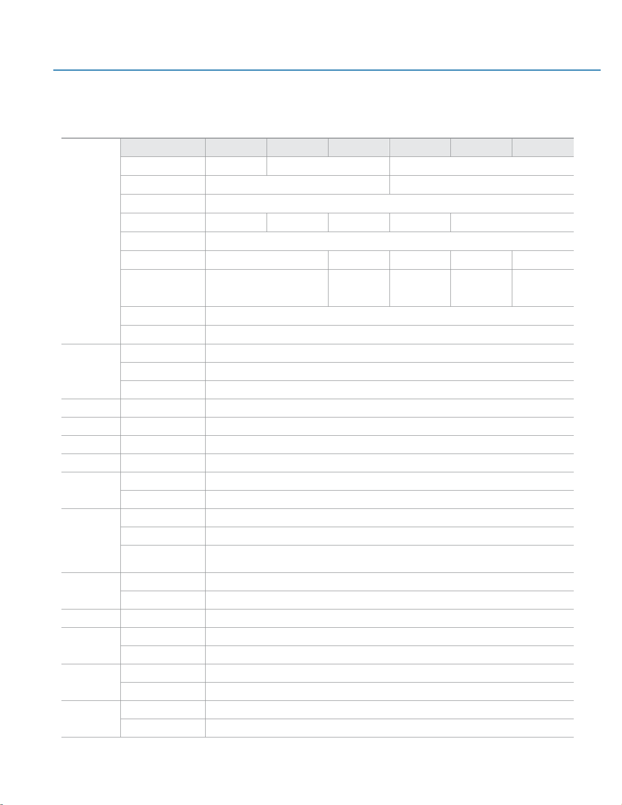
1.2 Specifications
Display
Display Size
7"
10"
12"
15"
19"
24"
Resolution
1024 x 600 WSVGA
1280 x 800 WXGA
1920 x 1080 Full HD
Format
Widescreen (16:10)
Widescreen (16:9)
Orientation
Landscape
Reading Angle (°)
150 (H) / 145 (V)
170 (H) / 170 (V)
176 (H) / 176 (V)
170 (H) / 170 (V)
178 (H) / 178 (V)
Display Off-Color
Black
Contrast
800:1
1000:1
800:1
1000:1
5000:1
Brightness (cd/m2)
500
(1000 with Outdoor SLR Screen)
400
(1000 with Outdoor
SLR Screen)
450
(1000 with Outdoor
SLR Screen)
350 300
MTBF Backlighting
50 000 h (at 25°C)
Backlight
LED, Dimmable via Software
Processor
i.MX 6DualLite
Processor
Freescale i.MX 6DualLite
# of cores/TDP
2 core/2.5W
CPU frequency
1.0Ghz
Memory
Capacity
2GB DDR3L
Storage
Internal
4GB eMMC NAND Flash Memory
Watchdog Timer
Setup
Setup by software
Operating Control
Method
Touch
Touchscreen
Technology
Projected Capacitive Touch (PCT/PCAP)
Touch Sensor
Multi-touch (Ten-Point)
Interfaces
Port 1
1 x 10/100/1000 Base T Ethernet RJ45
Port 2
1 x RS-232/422/485 COM Port (DB-9 connector)
Port 3
1 x USB 2.0 (Type-A)
1 x USB OTG (micro USB)
Status Indicators
Front Bezel Tri-color LED
Amber/Green/Red
On-board Buzzer
Yes (85dB sound level with 80mA mean current)
Power-Supply
Voltage [V]
+24VDC ±20% (19.2 V to 28.8 V, 3-Pin Connector)
Protection-Class
Front-Side
IP66 (When Installed to a Wall/Panel)
Back-Side
IP20
Operating System
OS
Linux kernel 4.1.15:Yocto
Framework
Qt 5.6.2
Software Tools
Tool 1
Qt WebKit / Web Browser
Tool 2
HTML5 Capability
Page 6
User Manual Section 1
GFK-3067 Rev. A May 2019
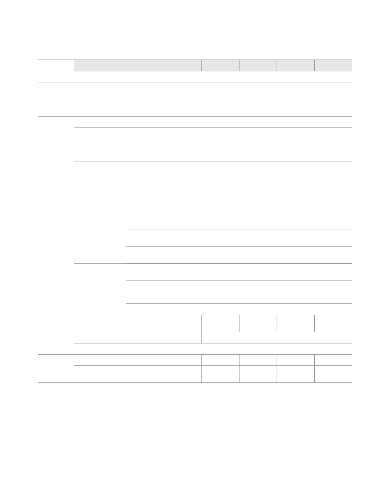
Getting Started 5
Secure &
Trusted Boot
Display Size
7"
10"
12"
15"
19"
24"
Item 1
CAAM
Design
Housing
Aluminum Die Casting (Front)
Construction Type
Modular (Detachable Modules; Computer, Monitor, Touch Display, DIO)
Cooling
Natural Convection (Fanless Passive Cooling)
Environment
Operating Temperature
-20°C to +65°C
Storage Temperature
-30°C to +70°C
Operating Humidity
85% RH (non- condensing) @ 30°C
Operating Altitude
10000 f t. (3.000 m)
Vibration
1Grms / 5 ~ 500Hz (Random) / Operation IEC 60068-2-64
10G peak acceleration (11 msec. duration)/operation IEC 60068-2-27
Compliance
Certifications
UL and cUL 62368, UL and cUL 61010, IECEE CB Scheme
UL TYPE 4 & 4X, IP66 (ANSI/IEC 60529)
CE (EN 62368, EN 61000-6-4, 61000-6-2)
FCC Part15 Class A
RoHS
Certifications
Coming Q4 2019
UL Listed US/CAN Hazardous Locations:
Class 1 Division 2, Class 2 Division 2, Class 3 Division 1
ATEX Zone 2/22 & IECEX
BIS
Marine; DNV, ABS, BV, LR
Mounting
Panel Cutout Dimensions
(W x H)
183.5 x 128.5 mm
255.5 x 174 mm
317 x 214.5 mm
398 x 245.5 mm
482 x 297 mm
581 x 360 mm
VESA Mounting
75 x 75
100 x 100
Hardware Included
Mounting Clamps and Allen Screws
Physical
Specifi cation
Net Weight (kg)
2.0
2.6
3.8
5.1
6.9
9.0
Dimensions (W x H x D)
192 x 137 x
65 mm
267 x 186.2 x
65 mm
329.1 x 226.8 x
66 mm
410.2 x 257.6 x
65 mm
500 x 315 x
70 mm
600 x 382 x
71 mm
Page 7
User Manual Section 1
GFK-3067 Rev. A May 2019
Getting Started 6
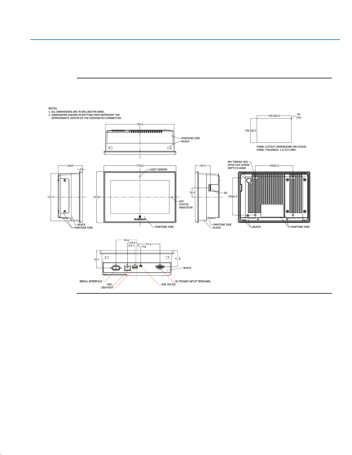
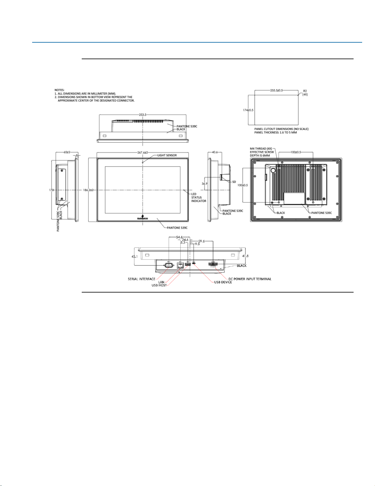
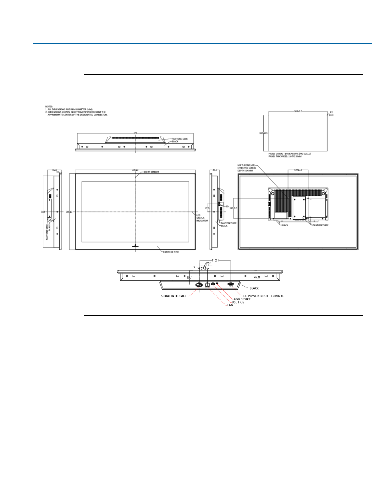
1.3 Technical Drawings & Dimensions
Figure 1.1 Dimensions of 7”
Page 8
User Manual Section 1
GFK-3067 Rev. A May 2019
Getting Started 7
Figure 1.2 Dimensions of 10”
Page 9
User Manual Section 1
GFK-3067 Rev. A May 2019
Getting Started 8
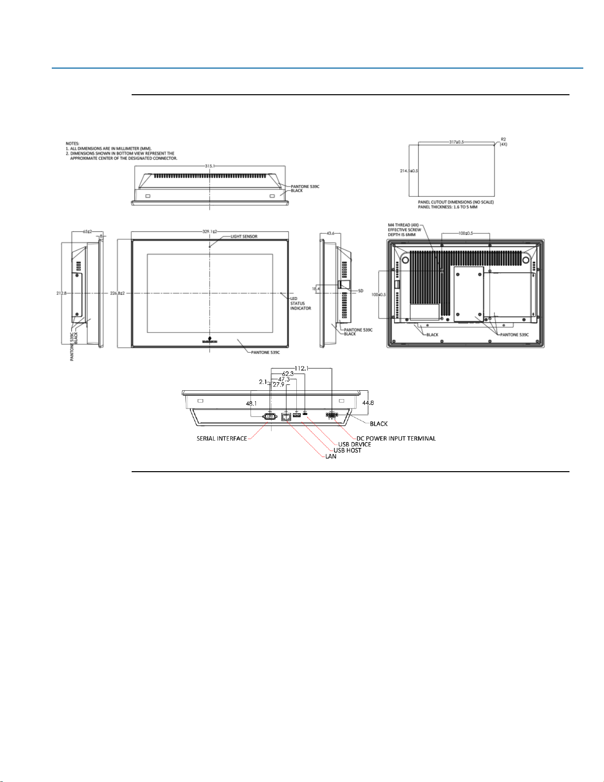
Figure 1.3 Dimensions of 12”
Page 10
User Manual Section 1
GFK-3067 Rev. A May 2019
Getting Started 9
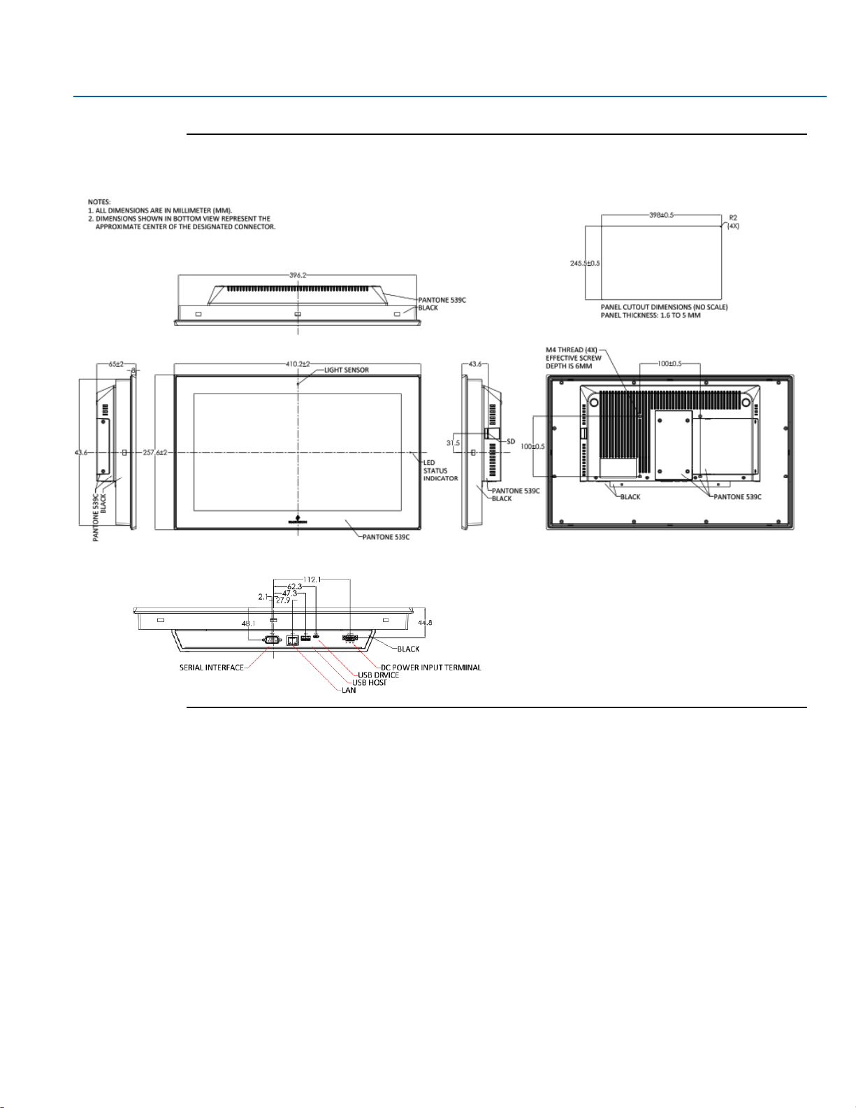
Figure 1.4 Dimensions of 15”
Page 11
User Manual Section 1
GFK-3067 Rev. A May 2019
Getting Started 10
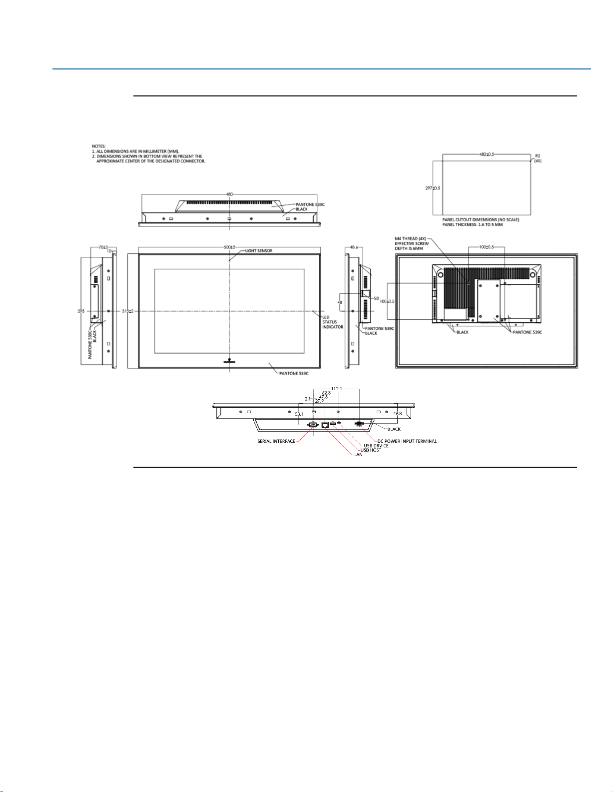
Figure 1.5 Dimensions of 19”
Page 12
User Manual Section 1
GFK-3067 Rev. A May 2019
Getting Started 11
Figure 1.6 Dimensions of 24”
Page 13
User Manual Section 1
GFK-3067 Rev. A May 2019
Getting Started 12
1.4 Brief Description of RXi – Web Panel
The RXi - Web Panel is powered by a Freescale i.MX 6 DualLite 1.0Ghz SoC which is coupled with 2GB of
onboard DDR3L memory. The Web Panel series comes in 7”, 10”, 12”, 15”, 19”, and 24” sizes, and
feature a high-resolution TFT LCD, 1 x USB 2.0 type A, 1 x USB OTG (micro USB), 1 x RS-232/422/485
COM Port (DB-9 connector)(Default RS-232), 1 x 10/100/1000 Base T Ethernet RJ45 and 1 x 3-pin DC
Power input terminal. The models come with a projected capacitive touch screen, and support +24VDC
±20% (19.2 V to 28.8 V, 3-Pin Connector), non-isolated power input.
Figure 1.7 Front View of 7”
Page 14

User Manual Section 1
GFK-3067 Rev. A May 2019
Getting Started 13
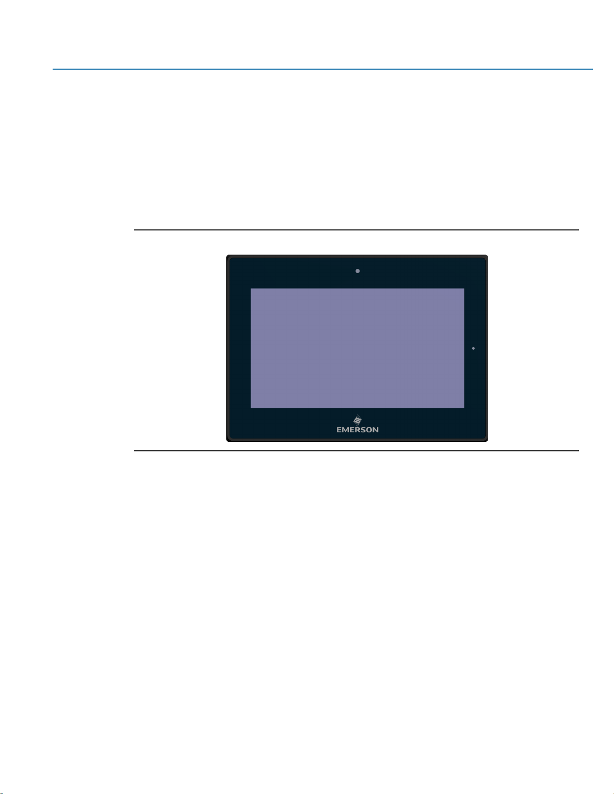
Figure 1.8 Front View of 10”
Figure 1.9 Front View of 12”
Page 15

User Manual Section 1
GFK-3067 Rev. A May 2019
Getting Started 14
Figure 1.10 Front View of 15”
Figure 1.11 Front View of 19”
Page 16
User Manual Section 1
GFK-3067 Rev. A May 2019
Getting Started 15
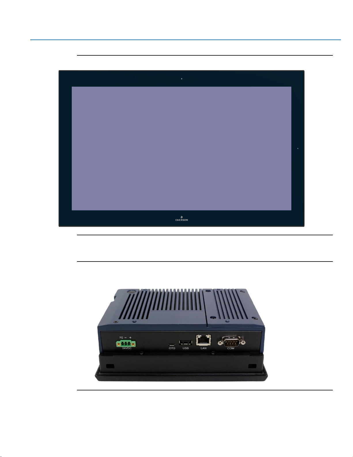
Figure 1.12 Front View of 24”
Figure 1.13 Rear View of 7”
Page 17

User Manual Section 1
GFK-3067 Rev. A May 2019
Getting Started 16
Figure 1.14 Rear View of 10”
Figure 1.15 Rear View of 12”
Page 18

User Manual Section 1
GFK-3067 Rev. A May 2019
Getting Started 17
Figure 1.16 Rear View of 15”
Figure 1.17 Rear View of 19”/24”
Page 19

User Manual Section 2
GFK-3067 Rev. A May 2019
Hardware 18
Section 2: Hardware
2.1 Key Features
Key features include:
•
Freescale ARM Cortex A9 i.MX6 Dual Lite 1.0GHz SoC
•
Onboard 2GB DDR3L SDRAM
•
Onboard 4GB eMMC Flash
•
1 x 10/100/1000M Ethernet
•
1 x RS232/422/485
•
1 x USB 2.0 Type A
•
1 x USB OTG, Micro USB
Page 20

User Manual Section 2
GFK-3067 Rev. A May 2019
Hardware 19
2.2 Motherboard Specifications
Board Size
170mm x 113mm, 10 Layers, 1.6mm
CPU Support
Freescale ARM Cortex A9 i.MX6 Dual Lite 1.0GHz
Memory Support
Onboard 2GB DDR3L SDRAM
Storage
Onboard 4GB eMMC Flash
Onboard Micro SD Card slot
Ethernet
1 x 10/100/1000MHz, RJ45 connector
Outside I/O
1 x USB 2.0, Type A connector
1 x RS-232/422/485, DB9 connector
1 x USB OTG, Micro USB connector
Internal I/O
1 x Debug port
Battery
CR2032 Coin Cell
Watchdog Timer
System Reset, Programmable via Software from 1 to 255 Seconds/Minutes
Temperature
Operating: -20 to 65°C
Storage: -40 to 70°C
Humidity
Storage: 10 to 90% @40°C
OS Support
Linux Kernel 4.9.11 + Chromium Browser 54.0.2810.2 (Chromium 54 Over)
Page 21

User Manual Section 2
GFK-3067 Rev. A May 2019
Hardware 20
2.3 Jumpers and Connectors Locations
2.3.1 Setting Jumper Functions
Before installing the Web Panel, please set the necessary functions following the chart below.
Note: To determine Pin 1 of the jumper and port, please observe the marking beside the plug. it will be
marked as “1”, a bolded line or a “△”; see the welding plate at back side, the square welding plate is Pin
1.
(1) Setting Jumper Functions (SW1)
SW1: 2bit switching ON/OFF, used to set the recording and the starting mode of the Motherboard.
SW1
ON
OFF
1.BOOT_MODE1_S
DOWNLOAD MODE
NORMAL MODE
2.BOOT_DEV
SD
DEFAULT
Figure 2.4 Jumper Function (SW1)
2.3.2 Socket Description
2.3.2.1 Connecting Input Power (24V DC-in)
To connect to power, follow these steps:
1. Verify that the power cable is not energized.
2. Loosen the screw clamps on the mating power connector.
3. Strip the insulation from the power cables.
4. Secure the power cable to the mating connector, noting polarity, and tighten the screw clamps.
The torque for the attaching screws is 0.3 Nm (2.26 in-lb).
Page 22
User Manual Section 2
GFK-3067 Rev. A May 2019
Hardware 21
5. Apply dc power to the unit. During normal startup and operation, the LED status indicator displays
as follows:
•
Solid amber while the RXi - Industrial Display unit is starting up
•
Solid green during normal operation
6. Once power is applied, the unit begins initializing. The first thing to display is the splash screen.
Be sure to connect a DC power cord to this 3-pin power connector. Using a voltage out of the range
may fail to boot the system or cause damage to the system board.
Before connecting the Web Panel to other devices, please read this manual carefully first to prevent
damage to the Motherboard.
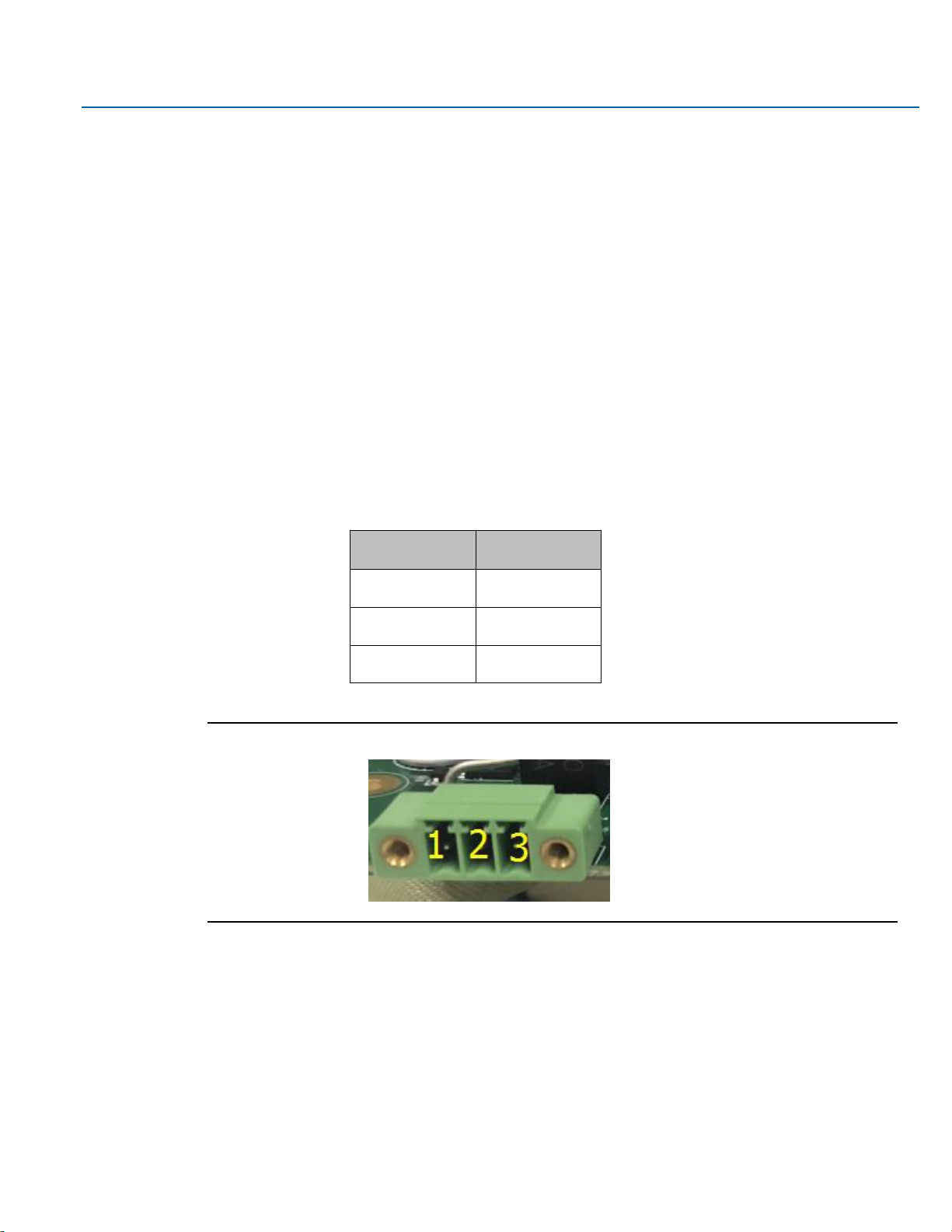
(1) Power Socket (DC_IN1)
DC_IN1: (Conn. Header Socket, 3.5mm, 1 x 3PIN), used to provide 24V voltage for the system.
DC_IN1 Pin#
Signal
Pin1
FG
Pin2
DC_IN-
Pin3
DC_IN+
Figure 2.5 Power Socket (DC_IN1)
(2) USB Socket (USB_OTG1/USB1)
USB_OTG1: Conn. Mini-USB, B-Type Female, SMD-5P With DIP 4pin, used to load system firmware
Page 23

User Manual Section 2
GFK-3067 Rev. A May 2019
Hardware 22
Figure 2.6 USB, LAN, and COM Ports
USB_OTG1 Pin#
Signal Name
1
5V_USB_OTG
2
USB_OTG_DN
3
USB_OTG_DP
4
USB0_ID
5
GND
USB1: Type A connector, supports USB devices.
USB_OTG1 Pin#
Signal Name
1
5V_USB_HOST1
2
USBDN_DM1
3
USBDN_DP1
4
GND
5
GND
6
GND
(3) LAN Socket (LAN1)
LAN 1: Conn. I/O Port, RJ45, 1000M, provide a solid RJ45 Ethernet Dock, GREEN denotes data transfer,
YELLOW verifies a connection to Internet.
Page 24

User Manual Section 2
GFK-3067 Rev. A May 2019
Hardware 23
(4) Connecting Socket (COM1)
COM1: Conn. I/O Port, RS232, DB9, Male. Standard DB9 port, provide 1 route for RS232/422/485.
COM1 Pin#
Signal Name
1
DCD1-_422TX-_485-
2
RXD1_422TX+_485+
3
TXD1_422RX+
4
DTR1-_422RX-
5
GND
6
NC
7
NC
8
NC
9
NC
(5) Debug Socket (DEBUG1)
DEBUG1: Conn. 1.25mm, (DF14 with pointing) SMD-4P, use for debugging information.
DEBUG Pin#
Signal Name
1
3P3V_S0_IO
2
UART1_TXD_DEBUG
3
UART1_RXD_DEBUG
4
GND
(6) SD-Card Socket (SD1)
SD1: Socket, mini SD/TF Card, 9 pin, SMD, supports SD/TF Card devices.
(7) BAT1 Socket (BAT1)
BAT1: BAT Socket, BS-10-A1B0J001, 20mm SMT, supports non-chargeable batteries. CR-2032
(8) Backlight Board Socket (BTB_MAIN_TB572B_1)
BTB_MAIN_TB-572B_1: Conn. Female, WCON, 2243-225M3CUT, 2 x 25P, 2.00mm, 180°, H=4.35,
10u”, SMD-50P, TB-572B Backlight Board Socket.
Page 25

User Manual Section 2
GFK-3067 Rev. A May 2019
Hardware 24
2.4 LED Indicators
2.4.1 Operation Status LEDs (Screen)
All RXi Industrial Displays have a tri-color LED built into the screen that provides visual indication of the
operation status.
LED State
System State
Amber, Solid
Operating system starting
Green, Solid
Normal operating state
Green, Blinking
Backlight off
Red, Blinking
Backlight failure
Off
Power not applied to unit
2.4.2 Ethernet Port Operation LEDs
LED
LED State
Operating State
Speed
Yellow, ON
10/100/1000
Link
Activity
Green, ON
Link Status
Page 26

User Manual Section 3
GFK-3067 Rev. A May 2019
Software Installation 25
Section 3: Software Installation
3.1 Installation Pictures
The following images show typical screens during software installation.
The operating system for the RXi – Web Panel is Linux.
Figure 3.1 Linux
The web browsers Chromium, and Firefox are both compatible with the RXi – Web Panel.
Figure 3.2 Chromium Browser
Page 27

User Manual Section 3
GFK-3067 Rev. A May 2019
Software Installation 26
Figure 3.3 Firefox Browser
Page 28

User Manual Section 4
GFK-3067 Rev. A May 2019
Mounting Information 27
Section 4: Mounting Information
4.1 Panel Mount
Figure 4.1 Panel Cutout Dimension Definitions
Width
Height
Display Size (in)
Width (mm)
Height (mm)
7
183.5
128.5
10
255.5
174
12
317
214.5
15
398
245.5
19
482
297
24
581
360
Page 29

User Manual Section 4
GFK-3067 Rev. A May 2019
Mounting Information 28
4.1.1 Panel Mount Installation Steps
1. Verify that the gasket is present and properly seated in the bezel channel located on the sides of
the unit
2. Insert the Web Panel into the mounting panel cutout
Figure 4.2 Panel Install View
3. Insert the hook of the mounting bracket into the mounting hole as displayed in the following
figure.
Figure 4.3 Mounting Bracket Insertion
Page 30

User Manual Section 4
GFK-3067 Rev. A May 2019
Mounting Information 29
4. Tighten the screws on the mounting bracket in a clock-wise direction.
Figure 4.4 Tighten Mounting Bracket
4.2 Mounting to Modular Display
Figure 4.5 7” Mount
Page 31

User Manual Section 4
GFK-3067 Rev. A May 2019
Mounting Information 30
Figure 4.6 10” Mount
Figure 4.7 12” Mount
Page 32

User Manual Section 4
GFK-3067 Rev. A May 2019
Mounting Information 31
Figure 4.8 15” Mount
Figure 4.9 19”/24” Mount
Page 33
User Manual Section 4
GFK-3067 Rev. A May 2019
Mounting Information 32
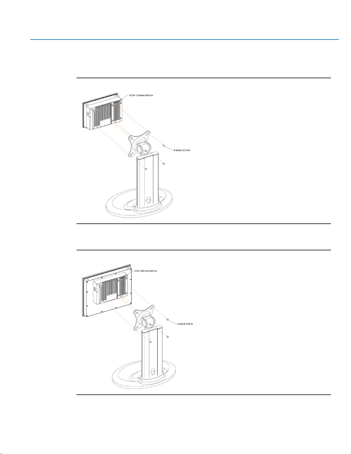
4.3 VESA Mount
Figure 4.10 7” VESA Mount
Figure 4.11 10” VESA Mount
Page 34

User Manual Section 4
GFK-3067 Rev. A May 2019
Mounting Information 33
Figure 4.12 12”/15” VESA Mount
Figure 4.13 19”/24” VESA Mount
Page 35

Contact Information:
North & South America
18703 GH Circle
PO Box 508
Waller, Texas 77484
USA
T +1 281 727 5300
2500 Park Avenue West
Mansfield, Ohio 44906
USA
T +1 419 529 4311
9009 King Palm Drive
Tampa , Florida 33619
USA
T +1 813 630 2255
4112-91A Street
Edmonton, Alberta T6E5V2
Canada
T +1 780 450 3600
Av. Hollingsworth,325
Iporanga
Sorocaba, SP 18087-105
Brazil
T +55 15 3238 3788
Europe
Asveldweg 11
7556 BT Hengelo(O)
The Netherlands
T +31 74 256 1010
Siemensring 112
D-47877 Willich
Germany
T +49 2154 499 660
30/36 Allee du Plateau
93250 Villemomble
France
T +331 48 122610
6 Bracken Hill
South West Industrial Estate
Peterlee, Co Durham
SR82LS, United Kingdom
T +44 191 518 0020
3 Furze Court
114 Wickham Road
Fareham, Hampshire
PO167SH ,United Kingdom
T +44 132 984 8900
Via Montello 71/73
20038 Seregno
Italy
T +39 0362 2285207
Selska cesta 93
10000 Zagreb
Croatia
T +385 913654292
ul. Konstruktorska str 11A
02-673 Warsaw
Poland
T +48 22 4589237
Hungári körút 166-168
H-1146 Budapest
Hungary
T +36 14624034
Hajkova 2747/22
130 00 Praha 3
Czech Republic
T +42 2 81002666
Zelezniciarska 13
811 04 Bratislava
Slovakia
T +42 1252442071
Blegistrasse 21,
P.O. Box 1046
CH 6341 Baar
Switzerland
T +41 (41) 7686215
2-4, Gara Herastrau St.
District 2, Nova Building,
5th floor 020334 Bucharest
Romania
T +40 212062506
Icerenkoy MAh. Topcu Ibrahim
Sk.
No:13 K:4 Icerenkoy
Istanbul, Turkey
T +90 2165739848408
Middle East & Africa
2 Monteer Road, Isando
Kempton Park, 1600
South Africa
T +27 11 974 3336
PO Box 17033
Jebel Ali Free Zone
Dubai,
United Arab Emirates
T +971 4883 5235
Asia Pacific
19, Kian Teck Crescent,
Singapore 628885
T +65 6501 4600
471 Mountain Highway
Bayswater, Victoria 3153
Australia
T +61 3 9721 0200
9/F Gateway Building
No.10 Ya Bao Road
Chaoyang District
Beijing, P.R. China
T +86 10 5821 1188
No 15 Xing Wang Road
Wuqing Development Area
Tianjin 301700
P.R. China
T +86 22 8212 3300
Lot 13112, Mukim Labu,
Kawasan Perindustrian Nilai
71807 Nilai, Negeri Sembilan
Malaysia
T +60 6 799 2323
Delphi B Wing, 601 & 602
6th Floor, Central Avenue
Powai, Mumbai 400076
India
T +91 22 6662 0566
NOF Shinagawa Konan Building
1-2-5, Higashi-shinagawa
Shinagawa-Ku, Tokyo
140-0002 Japan
T +81 3 5769 6873
Please visit our website for up to date product data.
www.Emerson.com
All Rights Reserved.
We reserve the right to modify or improve the designs or specifications of the products mentioned in this manual at any time without notice. Emerson
does not assume responsibility for the selection, use or maintenance of any product. Responsibility for proper selection, use and maintenance of any
Emerson product remains solely with the purchaser.
©2017 Emerson Electric Co.
 Loading...