

Page 1
User Manual
GFK-3066
May 2019
RXi – Panel PC
Page 2

User Manual Contents
GFK-3066 Rev. A May 2019
Contents i
Page 3

User Manual Contents
GFK-3066 Rev. A May 2019
Contents ii
Contents
Section 1: Getting Started ................................................................ 7
1.1 Features .......................................................................................................................... 7
1.2 Specifications .................................................................................................................. 7
1.3 Technical Drawings & Dimensions ................................................................................ 10
1.4 Brief Description of RXi - Panel PC ................................................................................ 16
Section 2: Hardware ....................................................................... 23
2.1 Key Features ................................................................................................................. 23
2.2 Motherboard Specifications ......................................................................................... 24
2.2.1 Specifications ..................................................................................................... 24
2.3 I/O and Connectors ....................................................................................................... 25
2.3.1 Outside I/O ........................................................................................................ 25
2.3.2 Connecting Input Power (24V DC-in) ................................................................. 25
2.3.3 Graphics Interface ............................................................................................. 26
2.3.3.1 DP++ Port ................................................................................................. 26
2.3.3.2 BIOS Setting .............................................................................................. 26
2.3.4 RJ45 LAN Ports ................................................................................................... 26
2.3.4.1 Features .................................................................................................... 26
2.3.4.2 BIOS Setting .............................................................................................. 26
2.3.5 USB Ports ........................................................................................................... 27
2.3.5.1 BIOS Setting .............................................................................................. 27
2.3.5.2 Wake-On-USB Keyboard/Mouse ............................................................. 27
2.3.6 Serial Ports (UART) ............................................................................................ 27
2.3.7 Audio ................................................................................................................. 27
2.3.7.1 Rear Audio ................................................................................................ 27
2.3.7.2 BIOS Setting .............................................................................................. 28
2.3.8 I/O Connectors .................................................................................................. 28
2.3.8.1 Serial ATA (SATA) Connector ................................................................... 28
2.3.8.1.1 Features .............................................................................................. 28
2.3.8.1.2 BIOS Setting......................................................................................... 28
2.3.9 Expansion Slots .................................................................................................. 28
2.3.9.1.1 Micro SD Socket .................................................................................. 28
2.3.10 LVDS LCD Panel Connector ................................................................................ 28
Page 4

User Manual Contents
GFK-3066 Rev. A May 2019
Contents iii
2.3.10.1.1 BIOS Setting......................................................................................... 28
2.3.11 AIO/DIO Connector............................................................................................ 29
2.3.12 Battery ............................................................................................................... 29
2.4 LED Indicators ............................................................................................................... 29
2.4.1 Operation Status LEDs (Screen) ......................................................................... 29
2.4.2 Ethernet Port Operation LEDs ........................................................................... 30
Section 3: BIOS Setup ..................................................................... 31
3.1 BIOS Setup .................................................................................................................... 31
3.1.1 Submenu ........................................................................................................... 31
3.2 AMI BIOS Setup Utility .................................................................................................. 32
3.2.1 Accessing the BIOS ............................................................................................ 32
3.2.2 Main Menu ........................................................................................................ 32
3.2.3 System Language ............................................................................................... 32
3.2.4 System Date ....................................................................................................... 32
3.2.5 System Language ............................................................................................... 33
3.2.6 Advanced ........................................................................................................... 33
3.2.7 ACPI Settings...................................................................................................... 33
3.2.7.1 Enable ACPI Auto Configuration ............................................................... 34
3.2.7.2 Enable Hibernation ................................................................................... 34
3.2.7.3 ACPI Sleep State ........................................................................................ 34
3.2.8 Trusted Computing ............................................................................................ 34
3.2.8.1 Security Device Support............................................................................ 34
3.2.8.2 Pending Operation .................................................................................... 35
3.2.9 Wakeup Configuration ...................................................................................... 35
3.2.9.1 Resume by PME ........................................................................................ 35
3.2.9.2 Resume by USB ......................................................................................... 35
3.2.10 CPU Configuration ............................................................................................. 36
3.2.10.1 SVM Mode ................................................................................................ 36
3.2.10.2 Core Leveling Mode .................................................................................. 36
3.2.10.3 Node 0 Information .................................................................................. 37
3.2.11 IDE Configuration .............................................................................................. 38
3.2.12 USB Configuration ............................................................................................. 38
3.2.13 Legacy USB Support ........................................................................................... 39
3.2.13.1.1 Enabled ............................................................................................... 39
Page 5

User Manual Contents
GFK-3066 Rev. A May 2019
Contents iv
3.2.13.1.2 Disabled .............................................................................................. 39
3.2.13.1.3 Auto..................................................................................................... 39
3.2.14 USB Mass Storage Driver Support ..................................................................... 39
3.2.15 NCT61120 Super IO Configuration .................................................................... 40
3.2.15.1 Serial Port ................................................................................................. 41
3.2.15.2 RS485 Auto Flow Support ......................................................................... 41
3.2.16 NCT 6112D HW Monitor .................................................................................... 41
3.2.17 NCT 6112D Super IO Features ........................................................................... 41
3.2.17.1 WatchDog Count Mode ............................................................................ 42
3.2.17.2 WatchDog Timeout Value ......................................................................... 42
3.2.18 Network Stack Configuration ............................................................................ 42
3.2.18.1 Network Stack........................................................................................... 43
3.2.18.2 Ipv4 PXE Support ...................................................................................... 43
3.2.18.3 Ipv6 PXE Support ...................................................................................... 43
3.2.18.4 PXE boot wait time ................................................................................... 43
3.2.18.5 Media detect time .................................................................................... 43
3.3 Chipset .......................................................................................................................... 44
3.3.1 OnChip SATA Channel ........................................................................................ 45
3.3.2 OnChip SATA Type ............................................................................................. 45
3.3.3 SD Mode ............................................................................................................ 45
3.3.4 SD Host Controller Version ................................................................................ 46
3.3.5 SD Host Controller Version ................................................................................ 46
3.3.5.1 Auto .......................................................................................................... 46
3.3.5.2 Disabled .................................................................................................... 46
3.3.5.3 Enabled ..................................................................................................... 47
3.3.6 Restore on AC power loss .................................................................................. 47
3.3.6.1 Power On .................................................................................................. 47
3.3.6.2 Power Off .................................................................................................. 47
3.3.6.3 Last State .................................................................................................. 47
3.3.7 GPP2 Hotplug Mode Control ............................................................................. 47
3.3.8 GPP3 Hotplug Mode Control ............................................................................. 48
3.3.9 DP0 Output Mode ............................................................................................. 49
3.3.10 DP1 Output Mode ............................................................................................. 49
3.3.11 Auto Backlight Dimming .................................................................................... 49
3.3.12 Minimum Dimming Level .................................................................................. 49
Page 6

User Manual Contents
GFK-3066 Rev. A May 2019
Contents v
3.3.13 Boot ................................................................................................................... 49
3.3.13.1 Setup Prompt Timeout ............................................................................. 49
3.3.13.2 Bootup NumLock State ............................................................................. 50
3.3.13.3 Quiet Boot ................................................................................................ 50
3.3.13.4 Boot Option #1/#2 .................................................................................... 50
3.3.14 Hard Drive BBS Priorities ................................................................................... 50
3.3.14.1 Launch CSM .............................................................................................. 51
3.3.14.2 Boot option filter ...................................................................................... 51
3.3.14.3 Launch PXE OpROM policy ....................................................................... 51
3.3.14.4 Launch Storage OpROM policy ................................................................. 51
3.3.14.5 Launch Video OpROM policy .................................................................... 51
3.4 Security ......................................................................................................................... 52
3.4.1 Administrator Password .................................................................................... 52
3.4.2 User Password ................................................................................................... 52
3.4.3 Secure Boot Menu ............................................................................................. 52
3.4.3.1 Secure Boot .............................................................................................. 53
3.4.3.2 Secure Boot Mode .................................................................................... 53
3.4.4 Key Management .............................................................................................. 53
3.4.4.1 Default Key Provision ................................................................................ 53
3.4.4.2 Enroll All Factory Default Keys .................................................................. 53
3.4.4.3 Set new PK ................................................................................................ 54
3.4.4.4 Set new KEK .............................................................................................. 54
3.4.4.5 Append KEK .............................................................................................. 54
3.4.4.6 Set new DB................................................................................................ 54
3.4.4.7 Append DB ................................................................................................ 54
3.4.4.8 Set new DBX ............................................................................................. 54
3.4.4.9 Append DBX .............................................................................................. 54
3.4.4.10 Set new DBT .............................................................................................. 54
3.4.4.11 Append DBT .............................................................................................. 54
3.5 Save & Exit .................................................................................................................... 55
3.5.1 Menu Options .................................................................................................... 55
3.5.1.1 Save Changes and Reset ........................................................................... 55
3.5.1.2 Discard Changes........................................................................................ 55
3.5.1.3 Restore Defaults ....................................................................................... 55
3.5.2 Updating the BIOS ............................................................................................. 55
Page 7

User Manual Contents
GFK-3066 Rev. A May 2019
Contents vi
Section 4: Installation of Drivers .................................................... 56
4.1 Drivers Installation Instruction ..................................................................................... 56
Section 5: Mounting Information ................................................... 60
5.1 Panel Mount ................................................................................................................. 60
5.1.1 Panel Cutout Dimensions .................................................................................. 60
5.1.2 Installation Steps ............................................................................................... 61
5.2 Mounting to Modular Display ....................................................................................... 62
5.3 VESA Mount .................................................................................................................. 65
5.3.1 VESA Mount Dimensions ................................................................................... 65
Page 8
User Manual Section 1
GFK-3066 Rev. A May 2019
Getting Started 7
Section 1: Getting Started
1.1 Features
Primary technical features:
•
7”/ 10”/ 12”/ 15”/ 19”/ 24” Industrial Widescreens
•
7”/ 10”/ 12”/ 15” Industrial Widescreen Outdoor Sunlight Readable Screens
•
Modular Design
•
AMD Embedded G-Series SOC Processor
•
Onboard DDR3L, up to 8GB (Soldered with ECC)
•
1 x SSD Slot
•
Flat Front Panel Projected Capacitive Touch Screens
•
Fanless Design
•
24VDC Wide Range Power Input
1.2 Specifications
Display
Display Size
7"
10"
12"
15"
19"
24"
Reso lution
1024 x 600
WSVGA
1280 x 800 WXGA
1920 x 1080 Full HD
Form at
Widescre en (16:10)
Widescreen (16:9)
Orie ntation
Land-Scap e
Reading Ang le (°)
150 (H) / 145 (V)
170 (H) / 170 (V)
176 (H) / 176 (V)
170 (H) / 170 (V)
178 (H) / 178 (V)
Display Off- Color
Black
Con trast
800 :1
1000:1
800:1
1000:1
5000:1
Brightne ss (cd/m2)
500
(1000 with Outdoor SLR Screen)
400
(1000 with
Outdoor SLR
Screen)
450
(1000 with
Outdoor SLR
Screen)
350
300
Colors
16.2 M illion
MTBF Ba cklighting
50,000 h (at 25° C)
Back light
LED, Dimmable via
Softw are
Page 9

User Manual Section 1
GFK-3066 Rev. A May 2019
Getting Started 8
Processor
Display Size
7"
10"
12"
15"
19"
24"
Chip set
AMD Emb edded
G-Series SOC
Processor
GX-210HL
GX-412GC
# of core s/TDP
2/7W
4/15W
CPU fre quency/L2 C ache
1.0G hz/1MB
1.2Ghz/2MB
GPU fre quency
267Mhz
300Mhz
Memory
Capaci ty
4GB or 8GB DDR3L
(Soldered with ECC, -40° C ~ 85°C)
Storage
Inter nal
32 / 64 / 128GB MLC SSD
(SATA Slim, -40°C ~ 85°C)
64 / 128GB MLC SSD
(SATA Slim, -40°C ~ 85°C)
Exter nal Slot
1 x Exter nal Micro SD/ SDHC Card Slot (up to 32GB)
Watchdog
Timer
Timer Levels
255 timer l evels, set up by softwa re
Operating Control
Method
Touch
Touchscreen
Technolo gy
Projected Capacitive Touch
(PCT/PCAP)
Touch Se nsor
Multi-touch
(Ten-Point )
Interfaces
Port 1
2 x 10/100/1000
Base T Eth ernet RJ45
4 x 10/100/1000
Base T Ethernet RJ45
Port 2
1 x RS-232 COM Port (5-Pin Connector, Isolated)
1 x RS-485 COM Port (5-Pin Connector, Isolated)
Port 3
2 x USB 3.0 (Typ e-A)
2 x USB 3.0 (Type-A)
2 x USB 2.0 (Type-A)
Port 4
1 x DisplayPor t
Port 5
1 x Mic In (M ono) (3.5mm Ja ck)
Port 6
1 x Line Out (Stereo) (3.5mm Jack)
Status Indicators
Front B ezel
Tri-color LED
Amber / G reen / R ed
On-board Buzzer
Yes (85dB sou nd level with 80m A mean current)
Power-Supply
Voltage [V]
+24VDC ±20%
(19.2 V to 28.8 V, 3-Pin Connecto r, Isolated)
Power
Consummption
Maximum Wattage [W]
20 W
23 W
33 W
39 W
35 W
52 W
Page 10

User Manual Section 1
GFK-3066 Rev. A May 2019
Getting Started 9
Protection-Class
Display Size
7"
10"
12"
15"
19"
24"
Fron t-Side
IP66 (When Installed to a Wall/P anel)
Back -Side
IP20
Operating System
Install ed Standard
Windows 10 IOT Enterpri se LTSB
Software Tools
Tool 1
Secure & Trusted Boot Capability
Tool 2
DHCP-Client , Web Browser (IE or FireFox ), Java JRE Ca pability
Secure & Trusted
Boot
Item 1
On-Board TPM2.0
Design
Hous ing
Aluminum Die Casting ( Front)
Constru ction Type
Modular
(Detachable Module s; Computer, Monit or, Touch Display, DIO)
Cooling
Natural Convect ion (Fanless P assive Cooling)
Opera ting Tempe rature
-20°C to +6 5°C
Storage Tempera ture
-30°C to +70° C
Opera ting Hum idity
85% RH (non- condensing) @ 30°C
Opera ting Altitude
10000 f t. (3.000 m)
Vibrat ion
1Grms / 5 ~ 500Hz (Random) / Operation IEC 60068-2-64
10G peak acceleration (11 msec. duration)/operation IEC 60068-2-27
Compliance
Certi fications
UL and cU L 62368, UL and cU L 61010, IECEE CB Scheme
UL TY PE 4 & 4X, IP6 6 (ANSI/IEC 6 0529)
CE (EN 62368, EN 61000- 6-4, 61000-6 -2)
FCC Par t15 Class A
RoHS
Certi fications
Coming Q4 2019
UL Liste d US/CAN Haz ardous Locatio ns:
Class 1 Di vision 2, Clas s 2 Division 2, Class 3 Divisio n 1
ATEX Zone 2/22 & IECEX
BIS & Marine; DNV, ABS, BV
Mounting
Panel Cutout
Dimensi ons (mm)
1 83 .5 (W )
12 8. 5( H)
25 5. 5( W)
17 4( H)
31 7( W)
21 4. 5( H)
39 8( W)
245.5( H)
4 82(W)
297(H)
581( W)
360(H)
VESA Mo unting
75 x 7 5
10 0 x 10 0
Hardwa re Incl uded
Mounting Cla mps and Allen Screws
Physical
Specification
Net W eight ( kg)
2.0
2.6
3.8
5.1
6.9
9.0
Dime nsions ( mm)
192(W)
137(H)
65(D)
267(W)
186.2(H)
65(D)
329.1(W)
226.8 (H)
66(D)
410.2(W)
257.6(H)
65(D)
500(W)
315(H)
70(D)
600(W)
382(H)
71(D)
Page 11
User Manual Section 1
GFK-3066 Rev. A May 2019
Getting Started 10
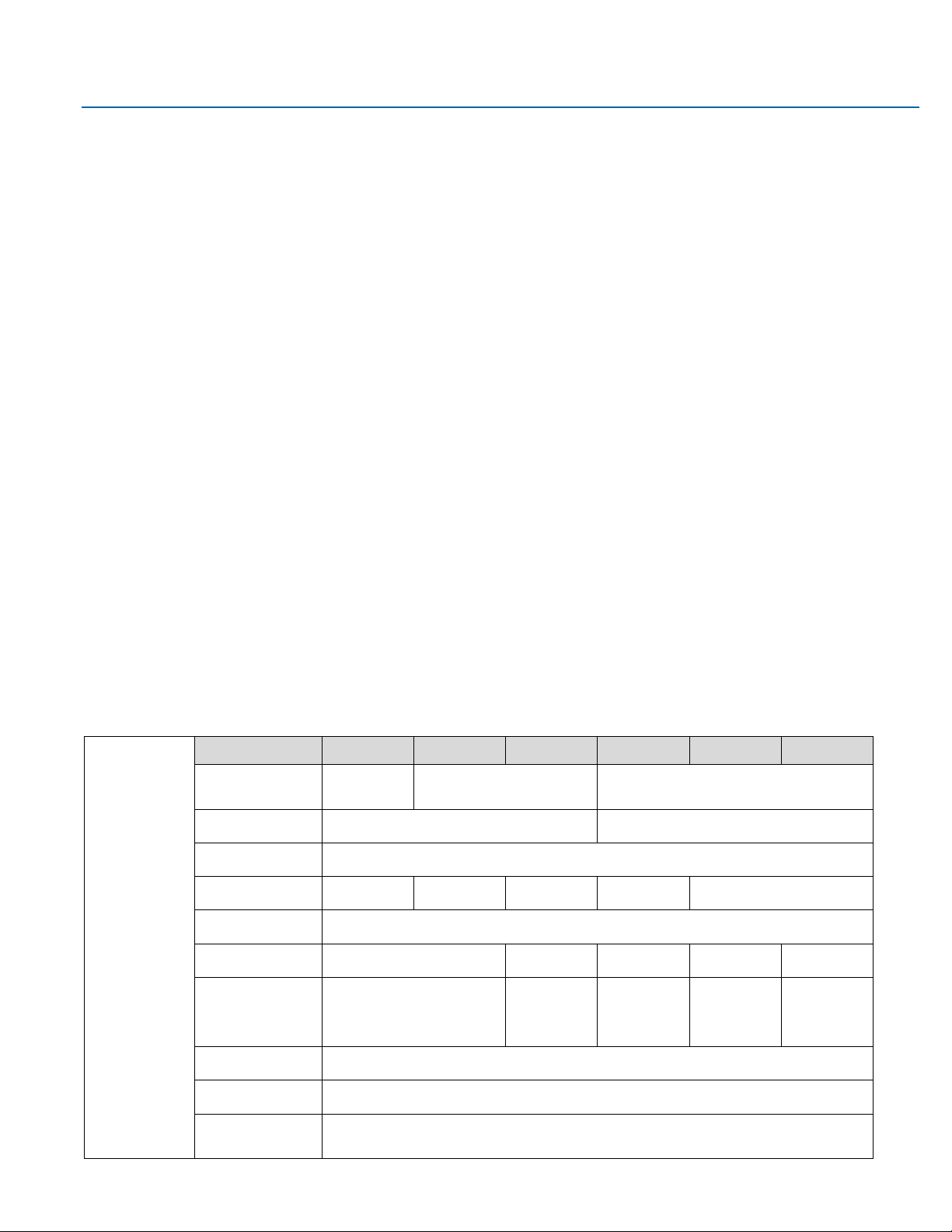
1.3 Technical Drawings & Dimensions
Figure 1.1 Dimensions of 7”
Page 12
User Manual Section 1
GFK-3066 Rev. A May 2019
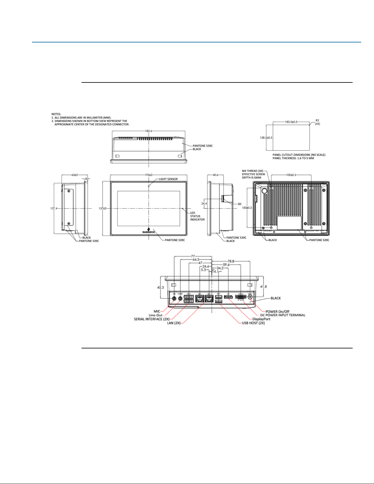
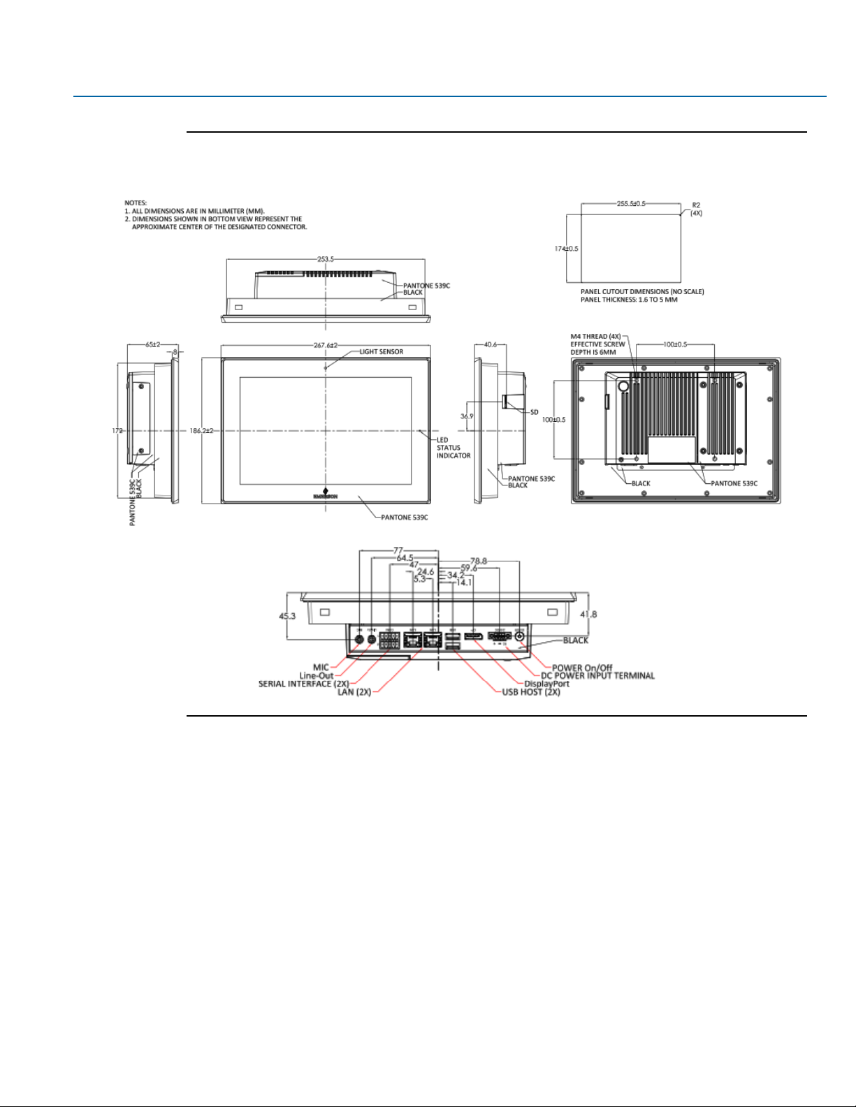
Getting Started 11
Figure 1.2 Dimensions of 10”
Page 13
User Manual Section 1
GFK-3066 Rev. A May 2019
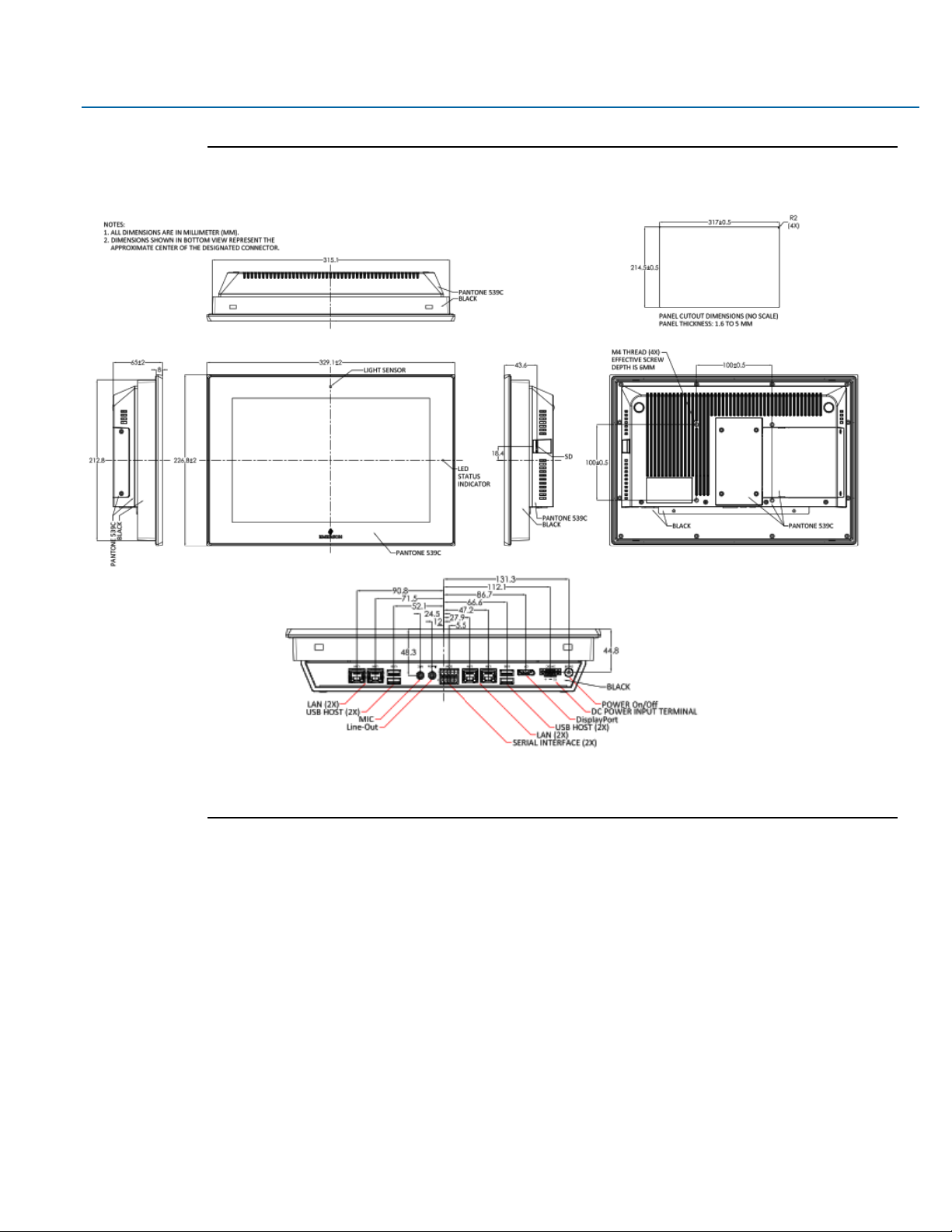
Getting Started 12
Figure 1.3 Dimensions of 12”
Page 14
User Manual Section 1
GFK-3066 Rev. A May 2019
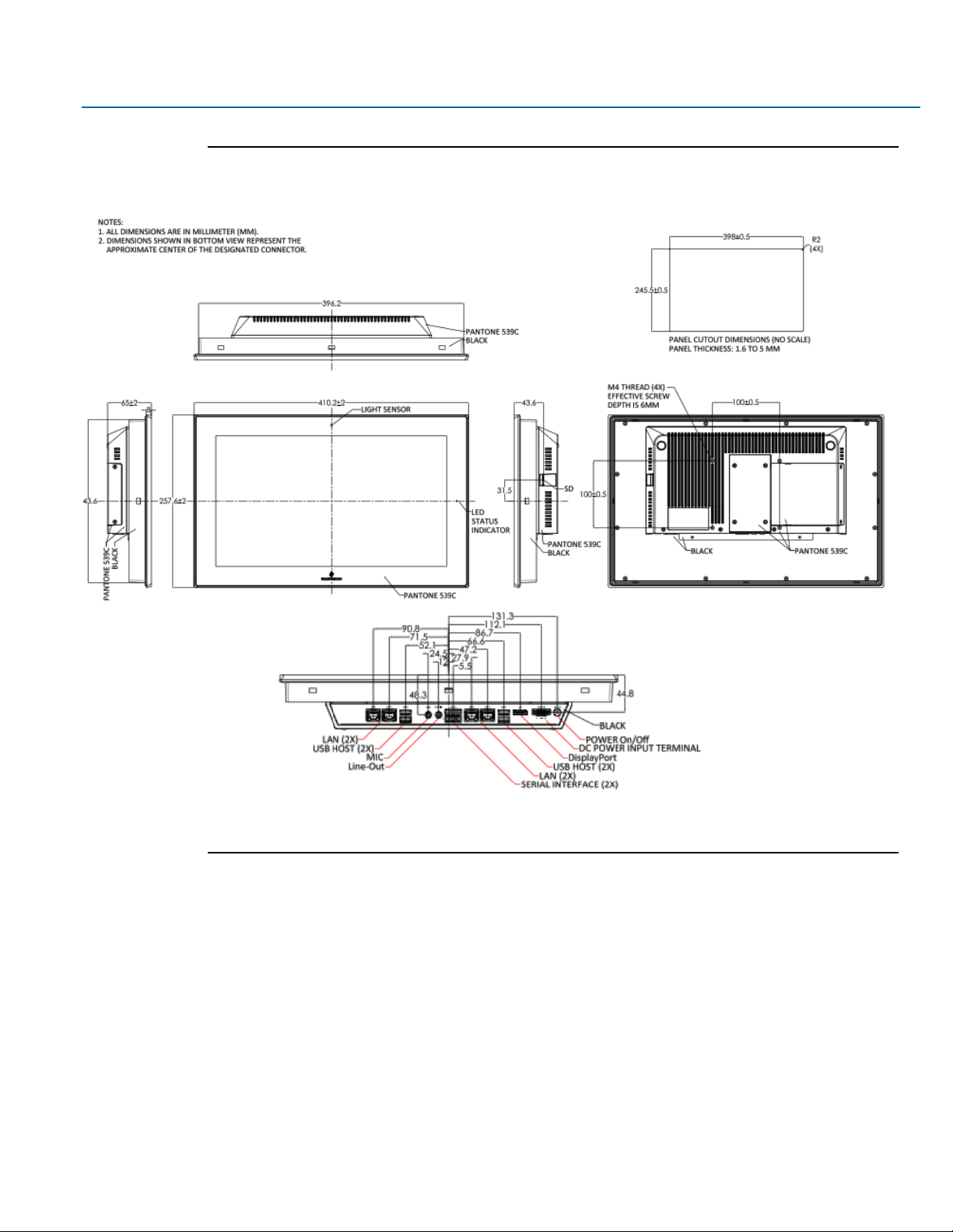
Getting Started 13
Figure 1.4 Dimensions of 15”
Page 15
User Manual Section 1
GFK-3066 Rev. A May 2019
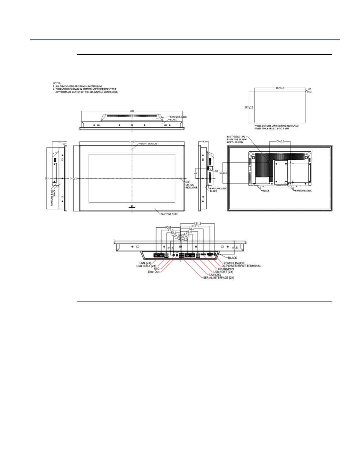
Getting Started 14
Figure 1.5 Dimensions of 19”
Page 16
User Manual Section 1
GFK-3066 Rev. A May 2019
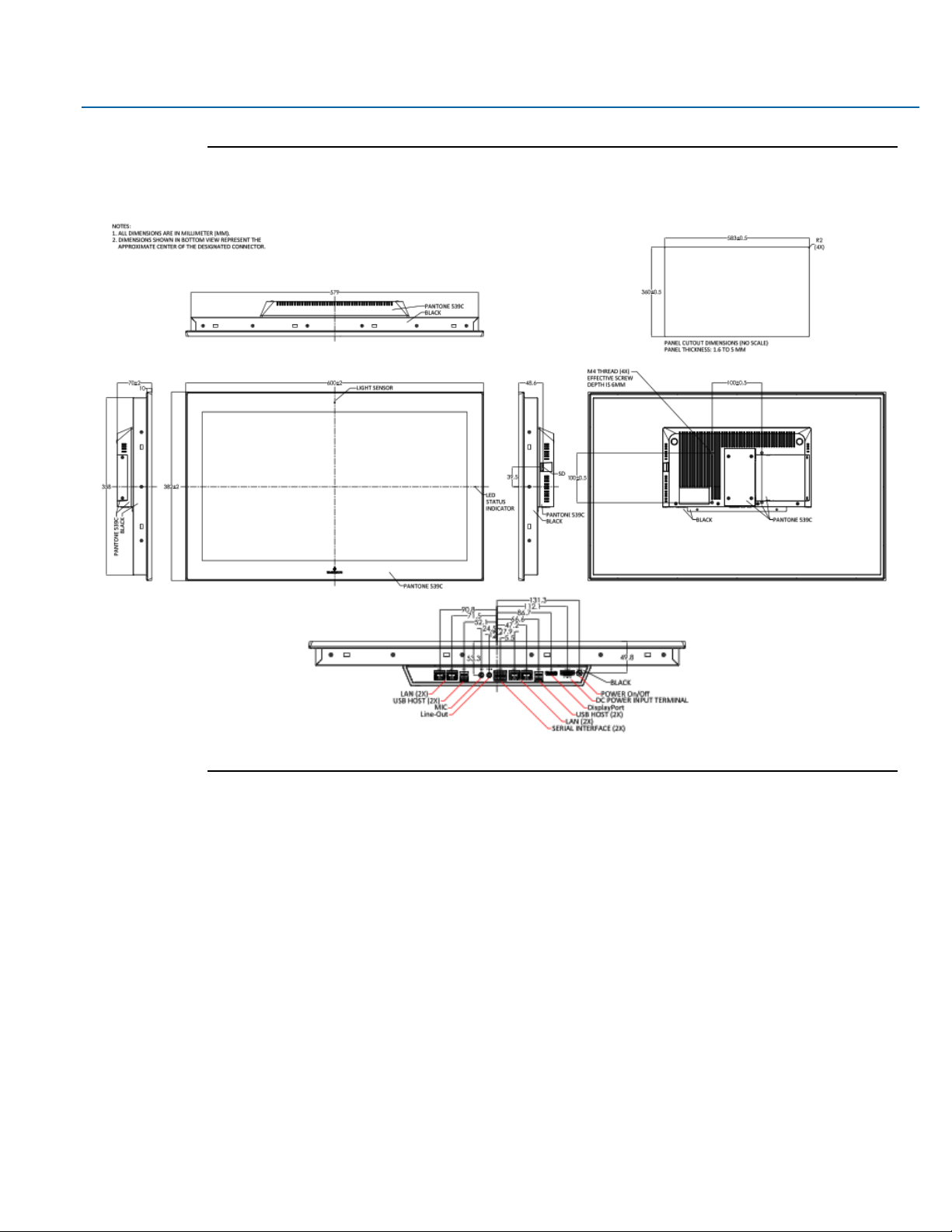
Getting Started 15
Figure 1.6 Dimensions of 24”
Page 17

User Manual Section 1
GFK-3066 Rev. A May 2019
Getting Started 16
1.4 Brief Description of RXi - Panel PC
The RXi - Panel PC modular display portfolio offers multiple options of separable screens and computing
units that maximize flexibility, performance, and durability. The portfolio ranges from 7" to 24" screens in a
widescreen format, with 7” to 15” models also available with outdoor sunlight readable screens. The
modular nature of the unit allows users to easily swap an indoor screen for an outdoor screen, change
screen sizes, or simply replace a damaged screen, while utilizing the same computing unit.
The RXi – Panel PC comes with either a Dual Core 1.0 GHz processor or a Quad Core 1.2GHz Processor with
4GB or 8GB of available DDR3 RAM with Windows 10 IOT Enterprise LTSB OS installed standard. The high
resolution, multitouch, projective capacitive screens can be used with personal protective equipment and
feature quick response times.
The outdoor rated sunlight readable screens are optically bonded and feature UV protection reducing
reflections and glare. All indoor and outdoor rated configurations carry the same certifications and
capabilities.
The entire RXi – Panel PC portfolio features IP66 rated screens that protect against dust, moisture, and even
direct water jets. The effective operating temperatures range as high as 65°C and as low as -20°C. With
Marine, ATEX/IECEX, and HazLoc certifications, the RXi - Panel PC provides you with a solution that is
designed to go where you need it to.
Figure 1.7 Front View of 7”
Page 18
User Manual Section 1
GFK-3066 Rev. A May 2019
Getting Started 17
Figure 1.8 Front View of 10”
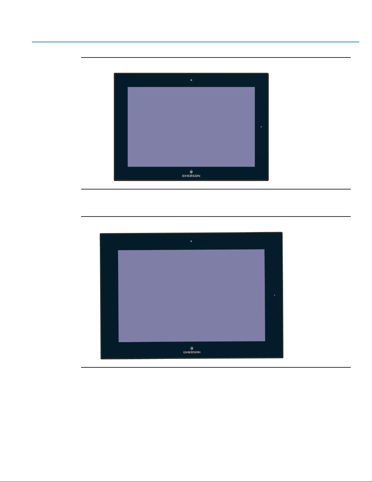
Figure 1.9 Front View of 12”
Page 19
User Manual Section 1
GFK-3066 Rev. A May 2019
Getting Started 18
Figure 1.10 Front View of 15”
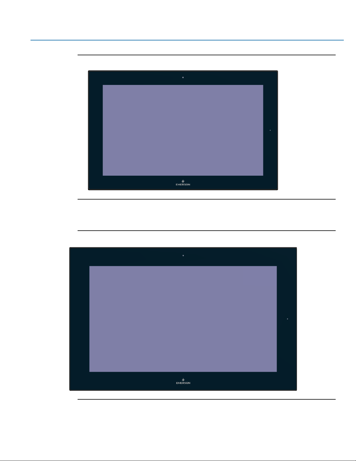
Figure 1.11 Front View of 19”
Page 20
User Manual Section 1
GFK-3066 Rev. A May 2019
Getting Started 19
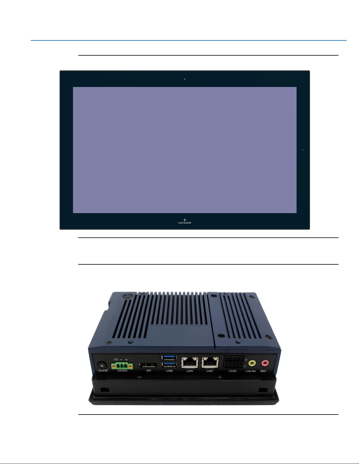
Figure 1.12 Front View of 24”
Figure 1.13 Rear View of 7”
Page 21
User Manual Section 1
GFK-3066 Rev. A May 2019
Getting Started 20
Figure 1.14 Rear View of 10”
Figure 1.15 Rear View of 12”
Page 22

User Manual Section 1
GFK-3066 Rev. A May 2019
Getting Started 21
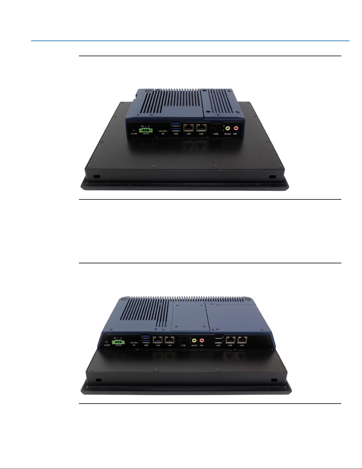
Figure 1.16 Rear View of 15”
Figure 1.17 Rear View of 19”
Page 23

User Manual Section 1
GFK-3066 Rev. A May 2019
Getting Started 22
Figure 1.18 Rear View of 24”
Page 24

User Manual Section 1
GFK-3066 Rev. A May 2019
BIOS Setup 23
Section 2: Hardware
2.1 Key Features
•
Watchdog Timer
•
DDR3
•
Graphics
•
Serial ATA
•
Gigabit LAN
•
Power Failure Recovery
•
USB
•
Wake-On-LAN
•
Wake-On-USB
•
ACPI-STR
•
RTC Timer
Page 25

User Manual Section 1
GFK-3066 Rev. A May 2019
BIOS Setup 24
2.2 Motherboard Specifications
2.2.1 Specifications
Board Size
170mm x 113mm
CPU Support
AMD® Embedded G-Series
AMD® GX-210HL, Dual Core, 1M Cache, 1.0GHz, 7W
AMD® GX-412GC, Quad Core, 2M Cache, 1.2GHz, 15W
Memory Support
On board 4GB/8GB DDR3L Memory with ECC
Supports Single Channel DDR3 1066/1333MHz
Graphics
AMD RadeonTM R3E GPU
DirectX® 11.2, OpenGL 4.3, OpenCLTM 1.2 graphics support
1 x DP++
1 x LVDS
DP++: resolution up to 4096x2160 @ 30Hz
LVDS: dual channel 24-bit, resolution up to 1920x1200 @ 60Hz
BIOS
AMI SPI 64Mbit
Storage
1 x Micro SD
1 x SATA 3.0 (7+15pin)
Ethernet
2 x Intel® I210IT, -40 to 105°C PCIe (10/100/1000Mbps)
Outside I/O
2 x USB 3.0
1 x RS-232
1 x RS-485
1 x Line-out
1 x Mic-in
2 x GbE (RJ-45)
1 x DP++
1 x Power Button
Internal I/O
1 x LVDS LCD Panel Connector
1 x AIO/DIO 1x30pin Connector (JAE TX24-30R-10ST-H1E)
Battery
CR2032 Coin Cell
Audio
Codec:92HD73C
Expansion
1 x Mini PCIe (PCIe/USB 2.0)
1 x M.2 E key 2230 (PCIe/USB 2.0)
Security
TPM2.0
Watchdog Timer
System Reset
Programmable via Software from 1 to 255 Seconds/Minutes
Temperature
Operating: -30 to 85°C
Storage: -30 to 85°C
Humidity
Operating: 10 to 90% RH
Storage: 10 to 90% RH
OS Support
Windows 10 IoT Enterprise (64-bit)
Page 26

User Manual Section 1
GFK-3066 Rev. A May 2019
BIOS Setup 25
2.3 I/O and Connectors
2.3.1 Outside I/O
The rear panel I/O port arrangement consists of the following:
• 1 power button
• 1 24V DC-in 3-pin power connector
• 1 DP++
• 2 USB 3.0 ports
• 2 RJ45 LAN ports
• 1 UART terminal-block
• 1 Line-out jack
• 1 Mic-in jack
Figure 2.1 Rear Panel Arrangement
2.3.2 Connecting Input Power (24V DC-in)
To connect to power, follow these steps:
1. Verify that the power cable is not energized.
2. Loosen the screw clamps on the mating power connector.
3. Strip the insulation from the power cables.
4. Secure the power cable to the mating connector, noting polarity, and tighten the screw clamps. The
torque for the attaching screws is 0.3 Nm (2.26 in-lb).
5. Apply dc power to the unit. During normal startup and operation, the LED status indicator displays as
follows:
•
Solid amber while the RXi - Industrial Display unit is starting up
Page 27

User Manual Section 1
GFK-3066 Rev. A May 2019
BIOS Setup 26
•
Solid green during normal operation
6. Once power is applied, the unit begins initializing. The first thing to display is the splash screen.
Be sure to connect a DC power cord to this 3-pin power connector. Using a voltage out of the range may fail
to boot the system or cause damage to the system board.
2.3.3 Graphics Interface
The display port consists of the following:
• 1 DP++ port
2.3.3.1 DP++ Port
The DP++ is a digital display interface used to connect a display device such as a computer monitor. It is
used to transmit audio and video simultaneously. The interface, which is developed by VESA, delivers higher
performance features than any other digital interface.
2.3.3.2 BIOS Setting
Configure the display device in the Chipset menu (“DISPLAY control” submenu) of the BIOS. Refer to the
chapter 3 for more information.
2.3.4 RJ45 LAN Ports
2.3.4.1 Features
2 Intel® I210IT PCI Express Gigabit Ethernet controllers (4 on larger box module)
The LAN ports allow the system board to connect to a local area network by means of a network hub or
router.
2.3.4.2 BIOS Setting
Configure the onboard LAN in the Advanced menu (“Wakeup Configuration” submenu) of the BIOS. Refer to
chapter 3 for more information.
Page 28

User Manual Section 1
GFK-3066 Rev. A May 2019
BIOS Setup 27
2.3.5 USB Ports
The USB ports allow for data exchange between your computer and a wide range of simultaneously
accessible external Plug and Play peripherals. The RXi – Panel PC is equipped with 2 onboard USB 3.0 ports
(USB 0-1) in the small configuration with an additional 2 USB 2.0 ports (USB 4-5) in the large box
configuration.
2.3.5.1 BIOS Setting
Configure the onboard USB in the Advanced menu (“Wakeup Configuration” submenu) of the BIOS. Refer to
chapter 3 for more information.
2.3.5.2 Wake-On-USB Keyboard/Mouse
The Wake-On-USB Keyboard/Mouse function allows you to use a USB keyboard or USB mouse to wake up a
system from the S3 (STR - Suspend To RAM) state.
2.3.6 Serial Ports (UART)
Serial
Connection
Pin
Function
RS232
1
TXD 2 RXD 3 RTS 4 CTS 5 GND
RS485
6
TX+ 7 TX- 8 RX+
9
RX-
10
GND
2.3.7 Audio
2.3.7.1 Rear Audio
The system board is equipped with 2 audio jacks (Line-out and Mic-in). A jack is a one-hole connecting
interface for inserting a plug.
• Line-out Jack (Lime)
This jack is used to connect a headphone or external speakers.
Page 29

User Manual Section 1
GFK-3066 Rev. A May 2019
BIOS Setup 28
• Mic-in Jack (Pink)
This jack is used to connect an external microphone.
2.3.7.2 BIOS Setting
Configure the onboard Audio device in the Chipset menu (“SB HD Azalia Configuration” submenu) of the
BIOS. Refer to the chapter 3 for more information.
2.3.8 I/O Connectors
2.3.8.1 Serial ATA (SATA) Connector
2.3.8.1.1 Features
• 1 Serial ATA 3.0 port with data transfer rate up to 6Gb/s
• Integrated Advanced Host Controller Interface (AHCI) controller
The Serial ATA connector is used to connect the Serial ATA device. Connect one end of the Serial ATA data
connector to a SATA connector on the other end to your Serial ATA device.
2.3.8.1.2 BIOS Setting
Configure the Serial ATA drive in the Chipset menu (“SB SATA Configuration” submenu) of the BIOS. Refer to
chapter 3 for more information.
2.3.9 Expansion Slots
2.3.9.1.1 Micro SD Socket
The micro SD socket allows you to install a micro SD card for the expansion of available storage.
2.3.10 LVDS LCD Panel Connector
The system board allows you to connect a LCD Display Panel with the LVDS LCD panel connector. This
connector transmits video signals and power from the system board to the LCD Display Panel.
Refer to the right side for the pin functions of LVDS connector.
2.3.10.1.1 BIOS Setting
Configure the LCD panel in the Chipset menu (“DISPLAY control” submenu) of the BIOS. Refer to Chapter 3
for more information.
Page 30

User Manual Section 1
GFK-3066 Rev. A May 2019
BIOS Setup 29
2.3.11 AIO/DIO Connector
AIO/DIO connector provides functionality to external devices that are connected to the connector. (FOR
FUTURE USE)
2.3.12 Battery
The lithium ion battery powers the real-time clock and CMOS memory. It is an auxiliary source of power
when the main power is shut off or disconnected. It is a standard CR2032 battery and is accessible on the
bottom of the computing module when separated from the screen (as shown below)
Safety Measures
• Danger of explosion if battery incorrectly replaced.
• Replace only with the same or equivalent type recommend by the manufacturer.
• Dispose of used batteries according to local ordinances.
2.4 LED Indicators
2.4.1 Operation Status LEDs (Screen)
All RXi Industrial Displays have a tri-color LED built into the screen that provides visual indication of the
operation status.
LED State
System State
Amber, Solid
Operating system starting
Green, Solid
Normal operating state
Green, Blinking
Backlight off
Red, Blinking
Backlight failure
Off
Power not applied to unit
Page 31

User Manual Section 1
GFK-3066 Rev. A May 2019
BIOS Setup 30
2.4.2 Ethernet Port Operation LEDs
LED
LED State
Operating State
Speed
Yellow, ON
10/100/1000
Link Activity
Green, ON
Link Status
Page 32

User Manual Section 1
GFK-3066 Rev. A May 2019
BIOS Setup 31
Section 3: BIOS Setup
3.1 BIOS Setup
The BIOS is a program that handles of the basic levels of communication between the CPU and peripherals.
It contains codes for various advanced features found in this system board. The BIOS allows you to configure
the system and save the configuration in a battery-backed CMOS so that the data is retained even when the
power is off. In general, the information stored in the CMOS RAM of the EEPROM will stay unchanged unless
a configuration change has been made such as a hard drive replaced or a device added.
It is possible for the CMOS battery to fail over time, causing CMOS data loss. If this happens, you need to
install a new CMOS battery and reconfigure the BIOS settings.
Keys
Function
Right and Left arrows
Moves the highlight left or right to select a menu.
Up and Down arrows
Moves the highlight up or down between submenu or fields.
<Enter>
Press <Enter> to enter the highlighted submenu or item.
+ (plus key)
Scrolls forward through the values or options of the highlighted field.
- (minus key)
Scrolls backward through the values or options of the highlighted field.
<F1>
Displays general help
<F2>
Pervious values
<F3>
Load Optimized Defaults
<F4>
Saves and resets the setup program.
<Esc>
Exit to the BIOS Setup Utility.
3.1.1 Submenu
When “” appears on the left of a particular field, it indicates that a submenu which contains additional
options are available for that field. To display the submenu, move the highlight to that field and press
<Enter>.
Page 33

User Manual Section 1
GFK-3066 Rev. A May 2019
BIOS Setup 32
3.2 AMI BIOS Setup Utility
3.2.1 Accessing the BIOS
To access the BIOS, you must attach a USB keyboard to the computing unit and repeatedly press F2 during
the start up sequence until it brings you to the Main Menu
3.2.2 Main Menu
The Main menu is the first screen that you will see when you enter the BIOS Setup Utility.
3.2.3 System Language
Choose the system default language.
3.2.4 System Date
The date format is <day>, <month>, <date>, <year>. Day displays a day, from Sunday to Saturday. Month
displays the month, from 01 to 12. Date displays the date, from 01 to 31. Year displays the year, from 1980
to 2099.
Page 34

User Manual Section 1
GFK-3066 Rev. A May 2019
BIOS Setup 33
3.2.5 System Language
The time format is <hour>, <minute>, <second>. The time is based on the 24-hour military-time clock. For
example, 1 p.m. is 13:00:00. Hour displays hours from 00 to
23. Minute displays minutes from 00 to 59. Second displays seconds from 00 to 59.
3.2.6 Advanced
The Advanced menu allows you to configure your system for basic operation. Some entries are defaults
required by the system board, while others, if enabled, will improve the performance of your system or
allow the user to set some features according to their preference.
3.2.7 ACPI Settings
This section configures system ACPI parameters.
Page 35

User Manual Section 1
GFK-3066 Rev. A May 2019
BIOS Setup 34
3.2.7.1 Enable ACPI Auto Configuration
This field is used to enable or disable BIOS ACPI auto configuration.
3.2.7.2 Enable Hibernation
This field is used to enable or disable the system’s ability to hibernate (OS/S4 Sleep State). This option may
be not be functional with all operating systems.
3.2.7.3 ACPI Sleep State
This field is used to select ACPI sleep state the system will enter when the SUSPEND button is pressed.
3.2.8 Trusted Computing
This section is used to configure the Trusted Computing settings.
3.2.8.1 Security Device Support
Enable or disable BIOS support for security device. The Operating System will not show security device. TCG
EFI protocol and INT1A interface will not be available.
Page 36

User Manual Section 1
GFK-3066 Rev. A May 2019
BIOS Setup 35
3.2.8.2 Pending Operation
Schedule an operation for the security device. Your computer will reboot during restart in order to change
state of security device.
3.2.9 Wakeup Configuration
This section is used to configure the Wakeup ACPI Power Management.
3.2.9.1 Resume by PME
Enable or disable to resume by PME (PCI, PCIe, LAN, etc.)
3.2.9.2 Resume by USB
Enable or disable to resume by USB.
Page 37

User Manual Section 1
GFK-3066 Rev. A May 2019
BIOS Setup 36
3.2.10 CPU Configuration
This section is used to configure the CPU. It will also display the detected CPU information.
3.2.10.1 SVM Mode
Enable or disable CPU Virtualization.
3.2.10.2 Core Leveling Mode
Select the number of cores in the system: Automatic mode, Three cores per processor, Two cores per
processor or One core per processor.
Page 38

User Manual Section 1
GFK-3066 Rev. A May 2019
BIOS Setup 37
3.2.10.3 Node 0 Information
View Memory Information related to Node 0.
Page 39

User Manual Section 1
GFK-3066 Rev. A May 2019
BIOS Setup 38
3.2.11 IDE Configuration
This section is used to configure the IDE Devices. It will also display the detected information.
3.2.12 USB Configuration
This section is used to configure the parameters of USB Device.
Page 40

User Manual Section 1
GFK-3066 Rev. A May 2019
BIOS Setup 39
3.2.13 Legacy USB Support
3.2.13.1.1 Enabled
Enable Legacy USB
3.2.13.1.2 Disabled
Keep USB devices available only for EFI applications.
3.2.13.1.3 Auto
Disable support for legacy when no USB devices are connected.
3.2.14 USB Mass Storage Driver Support
Enable or disable the support of the USB Mass Storage Driver.
Page 41

User Manual Section 1
GFK-3066 Rev. A May 2019
BIOS Setup 40
3.2.15 NCT61120 Super IO Configuration
This section is used to configure the parameters of the system super IO chip.
Page 42

User Manual Section 1
GFK-3066 Rev. A May 2019
BIOS Setup 41
3.2.15.1 Serial Port
Enable or disable the serial COM port.
3.2.15.2 RS485 Auto Flow Support
Enable or disable the RS485 auto flow support.
3.2.16 NCT 6112D HW Monitor
This section is used to monitor the hardware status.
3.2.17 NCT 6112D Super IO Features
This section is used to configure some control functions of the system super IO chip.
Page 43

User Manual Section 1
GFK-3066 Rev. A May 2019
BIOS Setup 42
3.2.17.1 WatchDog Count Mode
A WatchDog timer (WDT) is a hardware timer that automatically generates a system reset if the main
program neglects to periodically service it. It is often used to automatically reset an embedded device that
hangs because of a software or hardware fault. Use this menu to select the WatchDog Timer Unit: second or
minute.
3.2.17.2 WatchDog Timeout Value
Enter the value to set the Super IO WatchDog timer. 0 means disabled.
3.2.18 Network Stack Configuration
This section is used to enable or disable network stack settings. The Network Stack Controls LAN1 & LAN2
(Also LAN 3 & LAN4 on large computing module).
Page 44

User Manual Section 1
GFK-3066 Rev. A May 2019
BIOS Setup 43
3.2.18.1 Network Stack
Enable or disable UEFI network stack. When Network Stack is set to enabled, the screen will be displayed as
below.
3.2.18.2 Ipv4 PXE Support
When enabled, Ipv4 PXE boot supports. When disabled, Ipv4 PXE boot option will not be available.
3.2.18.3 Ipv6 PXE Support
When enabled, Ipv6 PXE boot supports. When disabled, Ipv6 PXE boot option will not be available.
3.2.18.4 PXE boot wait time
Enter the wait time value to abort the PXE boot.
3.2.18.5 Media detect time
Enter the wait time in seconds to detect media.
Page 45

User Manual Section 1
GFK-3066 Rev. A May 2019
BIOS Setup 44
3.3 Chipset
This section configures relevant chipset functions.
Page 46

User Manual Section 1
GFK-3066 Rev. A May 2019
BIOS Setup 45
3.3.1 OnChip SATA Channel
Enable or disable Serial ATA.
3.3.2 OnChip SATA Type
Select OnChip SATA Type: Native IDE, AHCI, or Legacy IDE.
3.3.3 SD Mode
Enable or disable Secure Digital (SD) Mode configuration.
Page 47

User Manual Section 1
GFK-3066 Rev. A May 2019
BIOS Setup 46
3.3.4 SD Host Controller Version
Select Secure Digital (SD) host controller version: SD2.0 or SD3.0.
3.3.5 SD Host Controller Version
Control the detection of the Azalia device.
3.3.5.1 Auto
HD Audio will be enabled if present, disabled otherwise.
3.3.5.2 Disabled
HD Audio will be fully disabled.
Page 48

User Manual Section 1
GFK-3066 Rev. A May 2019
BIOS Setup 47
3.3.5.3 Enabled
HD Audio will be fully enabled.
3.3.6 Restore on AC power loss
3.3.6.1 Power On
When power returns after an AC power failure, the system will automatically power-on.
3.3.6.2 Power Off
When power returns after an AC power failure, the system will remain off. You must press the Power button
to power on the system.
3.3.6.3 Last State
When power returns after an AC power failure, the system will return to the state
where you left off before power failure occurs. If the system’s power is off when AC
power failure occurs, it will remain off when power returns. If the system’s power is on when AC power
failure occurs, the system will power-on when power returns.
3.3.7 GPP2 Hotplug Mode Control
Enable or disable GPP2 hotplug mode control.
Page 49

User Manual Section 1
GFK-3066 Rev. A May 2019
BIOS Setup 48
3.3.8 GPP3 Hotplug Mode Control
Enable or disable GPP3 hotplug mode control.
Page 50

User Manual Section 1
GFK-3066 Rev. A May 2019
BIOS Setup 49
3.3.9 DP0 Output Mode
Select NB PCIe connect type (display device):eDP or Disabled.
3.3.10 DP1 Output Mode
Select NB PCIe connect type (display device): DP or Disabled.
3.3.11 Auto Backlight Dimming
Enable or disable dimming backlight by TB573D.
3.3.12 Minimum Dimming Level
Set the minimum dimming level control. The range is 1~20%.
3.3.13 Boot
3.3.13.1 Setup Prompt Timeout
Select the number of seconds to wait for the setup activation key. 65535(0xFFFF) denotes indefinite waiting.
Page 51

User Manual Section 1
GFK-3066 Rev. A May 2019
BIOS Setup 50
3.3.13.2 Bootup NumLock State
This allows you to determine the default state of the numeric keypad. By default, the system boots up with
NumLock on wherein the function of the numeric keypad is the number keys. When set to Off, the function
of the numeric keypad is the arrow keys.
3.3.13.3 Quiet Boot
Enable or disable Quiet Boot option.
3.3.13.4 Boot Option #1/#2
Select the system boot order.
3.3.14 Hard Drive BBS Priorities
Set the order of the legacy devices in this group.
Page 52

User Manual Section 1
GFK-3066 Rev. A May 2019
BIOS Setup 51
3.3.14.1 Launch CSM
This field is used to enable or disable to launch CSM.
3.3.14.2 Boot option filter
This option controls what device(s) the system will boot to.
3.3.14.3 Launch PXE OpROM policy
This field controls the execution of UEFI and Legacy PXE OpROM.
3.3.14.4 Launch Storage OpROM policy
This field controls the execution of UEFI and Legacy Storage OpROM.
3.3.14.5 Launch Video OpROM policy
This field controls the execution of UEFI and Legacy Video OpROM.
Page 53

User Manual Section 1
GFK-3066 Rev. A May 2019
BIOS Setup 52
3.4 Security
3.4.1 Administrator Password
Set the administrator password.
3.4.2 User Password
Set the user password.
3.4.3 Secure Boot Menu
This section is used to configure customizable secure boot settings.
Page 54

User Manual Section 1
GFK-3066 Rev. A May 2019
BIOS Setup 53
3.4.3.1 Secure Boot
Enable or disable secure boot. Secure Boot can be enabled if: 1. System running in user mode with enrolled
platform key (PK); 2. CSM function is disabled.
3.4.3.2 Secure Boot Mode
Select secure boot mode: standard or custom. Custom mode enables users to change image execution
policy and manage secure boot keys.
3.4.4 Key Management
This section enables experienced users to modify secure boot variables.
3.4.4.1 Default Key Provision
Enable or disable to install factory default secure boot keys when system is in setup mode. When enabled, a
pop-up window will display. Select “Yes” and press <Enter> to install factory default keys.
3.4.4.2 Enroll All Factory Default Keys
Select “Yes” and press <Enter> to install ALL factory default keys, including PK, KEK, DB, DBX and DBT.
Change takes effect after reboot.
Page 55

User Manual Section 1
GFK-3066 Rev. A May 2019
BIOS Setup 54
3.4.4.3 Set new PK
Select “Yes” and press <Enter> to set a new PK or select “No” and press <Enter> to load it from a file on
external media.
3.4.4.4 Set new KEK
Select “Yes” and press <Enter> to set a new KEK or select “No” and press <Enter> to load it from a file on
external media.
3.4.4.5 Append KEK
Select “Yes” and press <Enter> to set a new KEK or select “No” and press <Enter> to load it from a file on
external media.
3.4.4.6 Set new DB
Select “Yes” and press <Enter> to set a new DB or select “No” and press <Enter> to load it from a file on
external media.
3.4.4.7 Append DB
Select “Yes” and press <Enter> to set a new DB or select “No” and press <Enter> to load it from a file on
external media.
3.4.4.8 Set new DBX
Select “Yes” and press <Enter> to set a new DBX or select “No” and press <Enter> to load it from a file on
external media.
3.4.4.9 Append DBX
Select “Yes” and press <Enter> to set a new DBX or select “No” and press <Enter> to load it from a file on
external media.
3.4.4.10 Set new DBT
Select “Yes” and press <Enter> to set a new DBT or select “No” and press <Enter> to load it from a file on
external media.
3.4.4.11 Append DBT
Select “Yes” and press <Enter> to set a new DBT or select “No” and press <Enter> to load it from a file on
external media.
Page 56

User Manual Section 1
GFK-3066 Rev. A May 2019
BIOS Setup 55
3.5 Save & Exit
3.5.1 Menu Options
3.5.1.1 Save Changes and Reset
To save the changes, select this field and then press <Enter>. A dialog box will appear. Select Yes to reset the
system after saving all changes made.
3.5.1.2 Discard Changes
To discard the changes, select this field and then press <Enter>. A dialog box will appear. Select Yes to reset
the system setup without saving any changes.
3.5.1.3 Restore Defaults
To restore and load the optimized default values, select this field and then press
<Enter>. A dialog box will appear. Select Yes to restore the default values of all the setup options.
3.5.2 Updating the BIOS
To update the BIOS, you will need the BIOS file and a flash utility. Please contact technical support or your
sales representative for the files.
Page 57

User Manual Section 4
GFK-3066 Rev. A May 2019
Installation of Drivers 56
Section 4: Installation of Drivers
4.1 Drivers Installation Instruction
1. Read the End User License Agreement and accept to start installation
2. Detecting hardware
Page 58

User Manual Section 4
GFK-3066 Rev. A May 2019
Installation of Drivers 57
3. Select Express Installation
4. Installing now
Page 59

User Manual Section 4
GFK-3066 Rev. A May 2019
Installation of Drivers 58
5. Radeon Software (17.7) has been installed and restarts the computer now
6. Select Custom Installation
7. Select your requirements of this installation
Page 60

User Manual Section 4
GFK-3066 Rev. A May 2019
Installation of Drivers 59
8. Complete the whole installation and restart the computer again
Page 61

User Manual Section 5
GFK-3066 Rev. A May 2019
Mounting Information 60
Section 5: Mounting Information
5.1 Panel Mount
5.1.1 Panel Cutout Dimensions
Panel Thickness: 1.6 to 5mm
All measurements within ±0.5mm
Figure 5.1 Panel Cutout Dimension Definitions
Width
Height
Display Size (in)
Width (mm)
Height (mm)
7
183.5
128.5
10
255.5
174
12
317
214.5
15
398
245.5
19
482
297
24
581
360
Page 62

User Manual Section 5
GFK-3066 Rev. A May 2019
Mounting Information 61
5.1.2 Installation Steps
1. Verify that the gasket is present and properly seated in the bezel channel located on the sides of the
unit
2. Insert the Panel PC into the mounting panel cutout
Figure 5.2 Panel Install View
3. Insert the hook of the mounting bracket into the mounting hole as displayed in the following figure.
Figure 5.3 Mounting Bracket Insertion
Page 63

User Manual Section 5
GFK-3066 Rev. A May 2019
Mounting Information 62
4. Tighten the screws on the mounting bracket in a clock-wise direction.
Figure 5.4 Tighten Mounting Bracket
5.2 Mounting to Modular Display
Figure 4.2 7” Mount
Page 64

User Manual Section 5
GFK-3066 Rev. A May 2019
Mounting Information 63
Figure 4.3 10” Mount
Figure 4.4 12” Mount
Page 65

User Manual Section 5
GFK-3066 Rev. A May 2019
Mounting Information 64
Figure 4.5 15” Mount
Figure 4.6 19”/24” Mount
Page 66

User Manual Section 5
GFK-3066 Rev. A May 2019
Mounting Information 65
5.3 VESA Mount
5.3.1 VESA Mount Dimensions
All 7 & 10”units include VESA Mount Dimensions of 75mm x 75mm. All 12” through 24” units include VESA
Mount Dimensions of 100mm x 100mm.
All units fastened with four M4x8 Screws
Figure 5.5 7” VESA Mount
Figure 5.6 10” VESA Mount
Page 67

User Manual Section 5
GFK-3066 Rev. A May 2019
Mounting Information 66
Figure 5.7 12” VESA Mount
Figure 5.8 15” VESA Mount
Page 68

User Manual Section 5
GFK-3066 Rev. A May 2019
Mounting Information 67
Figure 5.9 19”/24” VESA Mount
Page 69

Contact Us:
North & South America
18703 GH Circle
PO Box 508
Waller, Texas 77484
USA
T +1 281 727 5300
2500 Park Avenue West
Mansfield, Ohio 44906
USA
T +1 419 529 4311
9009 King Palm Drive
Tampa , Florida 33619
USA
T +1 813 630 2255
4112-91A Street
Edmonton, Alberta T6E5V2
Canada
T +1 780 450 3600
Av. Hollingsworth,325
Iporanga
Sorocaba, SP 18087-105
Brazil
T +55 15 3238 3788
Europe
Asveldweg 11
7556 BT Hengelo(O)
The Netherlands
T +31 74 256 1010
Siemensring 112
D-47877 Willich
Germany
T +49 2154 499 660
30/36 Allee du Plateau
93250 Villemomble
France
T +331 48 122610
6 Bracken Hill
South West Industrial Estate
Peterlee, Co Durham
SR82LS, United Kingdom
T +44 191 518 0020
3 Furze Court
114 Wickham Road
Fareham, Hampshire
PO167SH ,United Kingdom
T +44 132 984 8900
Via Montello 71/73
20038 Seregno
Italy
T +39 0362 2285207
Selska cesta 93
10000 Zagreb
Croatia
T +385 913654292
ul. Konstruktorska str 11A
02-673 Warsaw
Poland
T +48 22 4589237
Hungári körút 166-168
H-1146 Budapest
Hungary
T +36 14624034
Hajkova 2747/22
130 00 Praha 3
Czech Republic
T +42 2 81002666
Zelezniciarska 13
811 04 Bratislava
Slovakia
T +42 1252442071
Blegistrasse 21,
P.O. Box 1046
CH 6341 Baar
Switzerland
T +41 (41) 7686215
2-4, Gara Herastrau St.
District 2, Nova Building,
5th floor 020334 Bucharest
Romania
T +40 212062506
Icerenkoy MAh. Topcu Ibrahim Sk.
No:13 K:4 Icerenkoy
Istanbul, Turkey
T +90 2165739848408
Middle East & Africa
2 Monteer Road, Isando
Kempton Park, 1600
South Africa
T +27 11 974 3336
PO Box 17033
Jebel Ali Free Zone
Dubai,
United Arab Emirates
T +971 4883 5235
Asia Pacific
19, Kian Teck Crescent,
Singapore 628885
T +65 6501 4600
471 Mountain Highway
Bayswater, Victoria 3153
Australia
T +61 3 9721 0200
9/F Gateway Building
No.10 Ya Bao Road
Chaoyang District
Beijing, P.R. China
T +86 10 5821 1188
No 15 Xing Wang Road
Wuqing Development Area
Tianjin 301700
P.R. China
T +86 22 8212 3300
Lot 13112, Mukim Labu,
Kawasan Perindustrian Nilai
71807 Nilai, Negeri Sembilan
Malaysia
T +60 6 799 2323
Delphi B Wing, 601 & 602
6th Floor, Central Avenue
Powai, Mumbai 400076
India
T +91 22 6662 0566
NOF Shinagawa Konan Building
1-2-5, Higashi-shinagawa
Shinagawa-Ku, Tokyo
140-0002 Japan
T +81 3 5769 6873
Please visit our website for up to date product data.
www.Emerson.com
All Rights Reserved.
We reserve the right to modify or improve the designs or specifications of the products mentioned in this manual at any time without notice. Emerson does not
assume responsibility for the selection, use or maintenance of any product. Responsibility for proper selection, use and maintenance of any Emerson product
remains solely with the purchaser.
©2017 Emerson Electric Co.
 Loading...