

Page 1
User Manual
GFK-3065
May 2019
RXi – Industrial Monitor
Page 2

User Manual Contents
GFK-3065 Rev. A May 2019
Contents 2
Page 3

User Manual Contents
GFK-3065 Rev. A May 2019
Contents 3
Contents
Section 1: Getting Started ................................................................ 5
1.1 Features .......................................................................................................................... 5
1.2 Specifications .................................................................................................................. 6
1.3 Technical Drawings & Dimensions .................................................................................. 7
1.4 Brief Description of Industrial Display .......................................................................... 13
Section 2: Hardware ....................................................................... 19
2.1 Motherboard Specifications ......................................................................................... 19
2.2 Jumpers and Connectors Location ................................................................................ 21
2.2.1 Connecting Input Power (24V DC-in) ................................................................. 21
2.3 I/O and Connectors ....................................................................................................... 22
2.3.1 DC_IN1 ............................................................................................................... 22
2.3.2 HDMI (HDMI Input) ........................................................................................... 23
2.3.3 DP1 (Display Port Input) .................................................................................... 24
2.3.4 DP2 (Display Port Output) ................................................................................. 25
2.3.5 CN1 (Debug) - Reserved .................................................................................... 25
2.3.6 CN2 - Reserved .................................................................................................. 26
2.3.7 CN3 - Reserved .................................................................................................. 26
2.3.8 CN4 (OSD) .......................................................................................................... 26
2.3.9 CN5 (LVDS Output) ............................................................................................ 27
2.3.10 CN6 (USB 2.0) .................................................................................................... 28
2.3.11 CN7 (Line Out) ................................................................................................... 28
2.3.12 JP1 ..................................................................................................................... 29
2.3.13 JP2 ..................................................................................................................... 29
2.3.14 SW1 - Reserved ................................................................................................. 29
2.4 LED Indicators ............................................................................................................... 29
2.4.1 Operation Status LEDs (Screen) ......................................................................... 29
Section 3: OSD ............................................................................... 30
3.1 AD Board OSD Functions .............................................................................................. 30
3.1.1 Enter Burn-in Mode ........................................................................................... 30
3.1.2 Exit Burn-in Mode .............................................................................................. 31
3.1.2.1 If unable to exit Burn-in Mode ............................................................... 31
Page 4

User Manual Contents
GFK-3065 Rev. A May 2019
Contents 4
3.2 OSD Controls ................................................................................................................. 31
3.2.1 OSD Keypad ....................................................................................................... 31
3.2.2 Virtual OSD Keypad ........................................................................................... 32
3.3 Main Menu ................................................................................................................... 32
3.3.1 Picture ............................................................................................................... 32
3.3.2 Display ............................................................................................................... 33
3.3.3 Color .................................................................................................................. 34
3.3.4 Input .................................................................................................................. 35
3.3.5 Audio ................................................................................................................. 36
3.3.6 Other ................................................................................................................. 37
Section 4: Mounting Information ................................................... 38
4.1 Panel Mount ................................................................................................................. 38
4.1.1 Installation Steps ............................................................................................... 38
4.2 Mounting to Modular Display ....................................................................................... 39
4.3 VESA Mount .................................................................................................................. 41
Page 5

User Manual Section 1
GFK-3065 Rev. A May 2019
Getting Started 5
Section 1: Getting Started
1.1 Features
Primary technical features:
•
7”/ 10”/ 12”/ 15”/ 19”/ 24” Widescreen Display
•
TFT LCD Industrial Display
•
Aluminum chassis
•
HDMI, DP, DP-out(MST-daisy chain), Line-out, USB ports
•
OSD on the left side
•
DC 24V power input
Page 6

User Manual Section 1
GFK-3065 Rev. A May 2019
Getting Started 6
1.2 Specifications
Display
Size (inch)
7"
10"
12"
15"
19"
24"
Resolution
1024 x 600 WSVGA
1280 x 800 WXGA
1920 x 1080 Full HD
Format
Widescreen (16:0)
Widescreen (16:10)
Widescreen (16:9)
Orientation
Landscape
Reading Angle (°)
150 (H) / 145 (V)
170 (H) / 170 (V)
176 (H) / 176 (V)
170 (H) / 170 (V)
178 (H) / 178 (V)
Display Off-Color
Black
Contrast
800:1
1000:1
800:1
1000:1
5000:1
Brightness (cd/m2)
500
400
450
350
300
Brightness with Outdoor
SLR Screen (cd/m2)
1000
N/A
MTBF Backlighting
50 000 h (at 25°C)
Touchscreen
Technology
Projected Capacitive Touch (PCT/PCAP)
Touch Sensor
Multi-touch (Ten-Point)
Interfaces
Port 1
1 x HDMI-In
Port 2
1 x Display Port-In
Port 3
1 x Display Port-Out
Port 4
(MST - Daisy Chain)
Port 5
1 x USB Input (For Touch)
Status Indicators
Front Bezel Tri-color LED
Amber/Green/Red
Power-Supply
Voltage [V]
+24VDC ±20% (19.2 V to 28.8 V, 3-Pin Connector) Isolated
Protection-Class
Front-Side
IP66 (When Installed to a Wall/Panel)
Back-Side
IP20
Design
Housing
Aluminum Die Casting (Front)
Environment
Operating Temperature
-20°C to +65°C
Storage Temperature
-30°C to +70°C
Operating Humidity
85% RH (non- condensing) @ 30°C
Operating Altitude
10000 f t. (3.000 m)
Vibration
1Grms / 5 ~ 500Hz (Random) / Operation IEC 60068-2-64
10G peak acceleration (11 msec. duration)/operation IEC 60068-2-27
Compliance
Certifications
UL and cUL 62368, UL and cUL 61010, IECEE CB Scheme
UL TYPE 4 & 4X, IP66 (ANSI/IEC 60529)
CE (EN 62368, EN 61000-6-4, 61000-6-2)
FCC Part15 Class A
RoHS
Certifications Coming
Q4 2019
UL Listed US/CAN Hazardous Locations:
Class 1 Division 2, Class 2 Division 2, Class 3 Division 1
ATEX Zone 2/22 & IECEX
BIS
Mounting
Panel Cutout Dimensions
(W x H)
183.5 x 128.5 mm
255.5 x 174 mm
317 x 214.5 mm
398 x 245.5 mm
482 x 297 mm
581 x 360 mm
VESA Mounting
75 x 75
100 x 100
Hardware Included
Mounting Clamps and Allen Screws
Physical
Specif ication
Net Weight (kg)
2.0
2.6
3.8
5.1
6.9
9.0
Dimensions (W x H x D)
192 x 137 x
65 mm
267 x 186.2 x
65 mm
329.1 x 226.8 x
66 mm
410.2 x 257.6 x
65 mm
500 x 315 x
70 mm
600 x 382 x
71 mm
Page 7
User Manual Section 1
GFK-3065 Rev. A May 2019
Getting Started 7
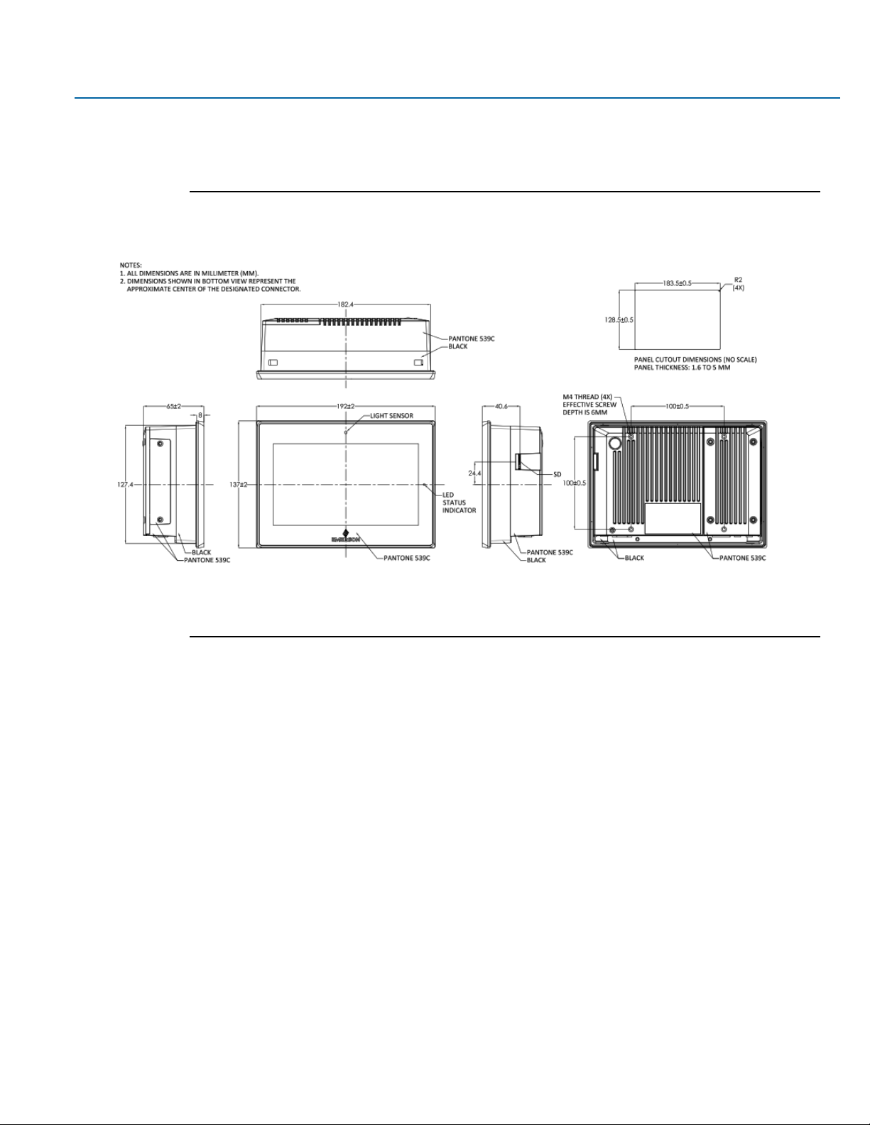
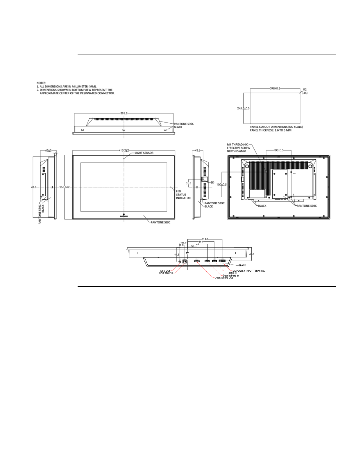
1.3 Technical Drawings & Dimensions
Figure 1.1 Dimensions of 7”
Page 8
User Manual Section 1
GFK-3065 Rev. A May 2019
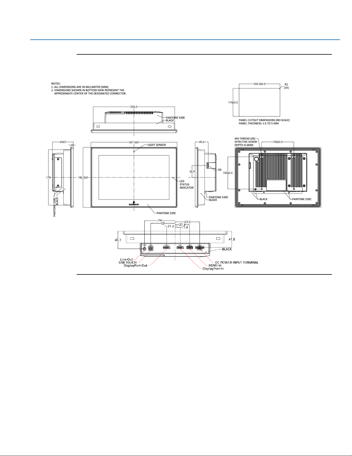
Getting Started 8
Figure 1.2 Dimensions of 10”
Page 9
User Manual Section 1
GFK-3065 Rev. A May 2019
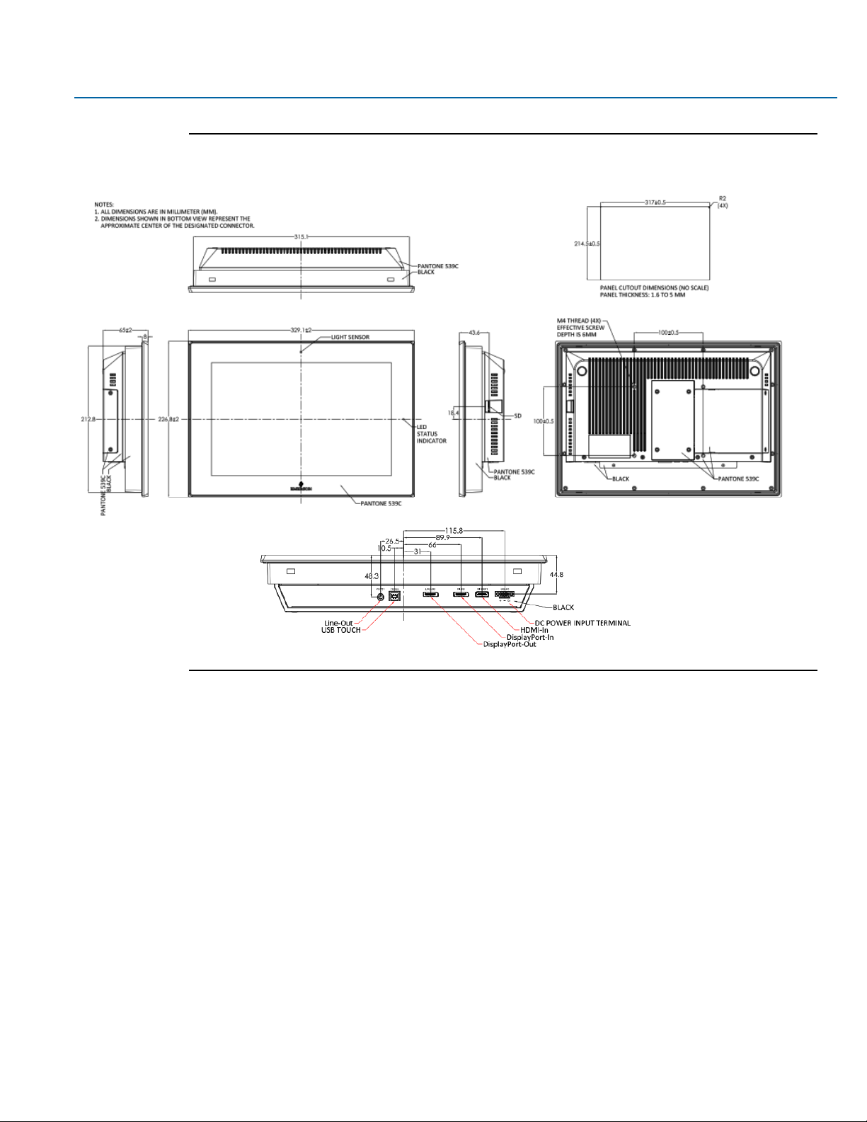
Getting Started 9
Figure 1.3 Dimensions of 12”
Page 10
User Manual Section 1
GFK-3065 Rev. A May 2019
Getting Started 10
Figure 1.4 Dimensions of 15”
Page 11
User Manual Section 1
GFK-3065 Rev. A May 2019
Getting Started 11
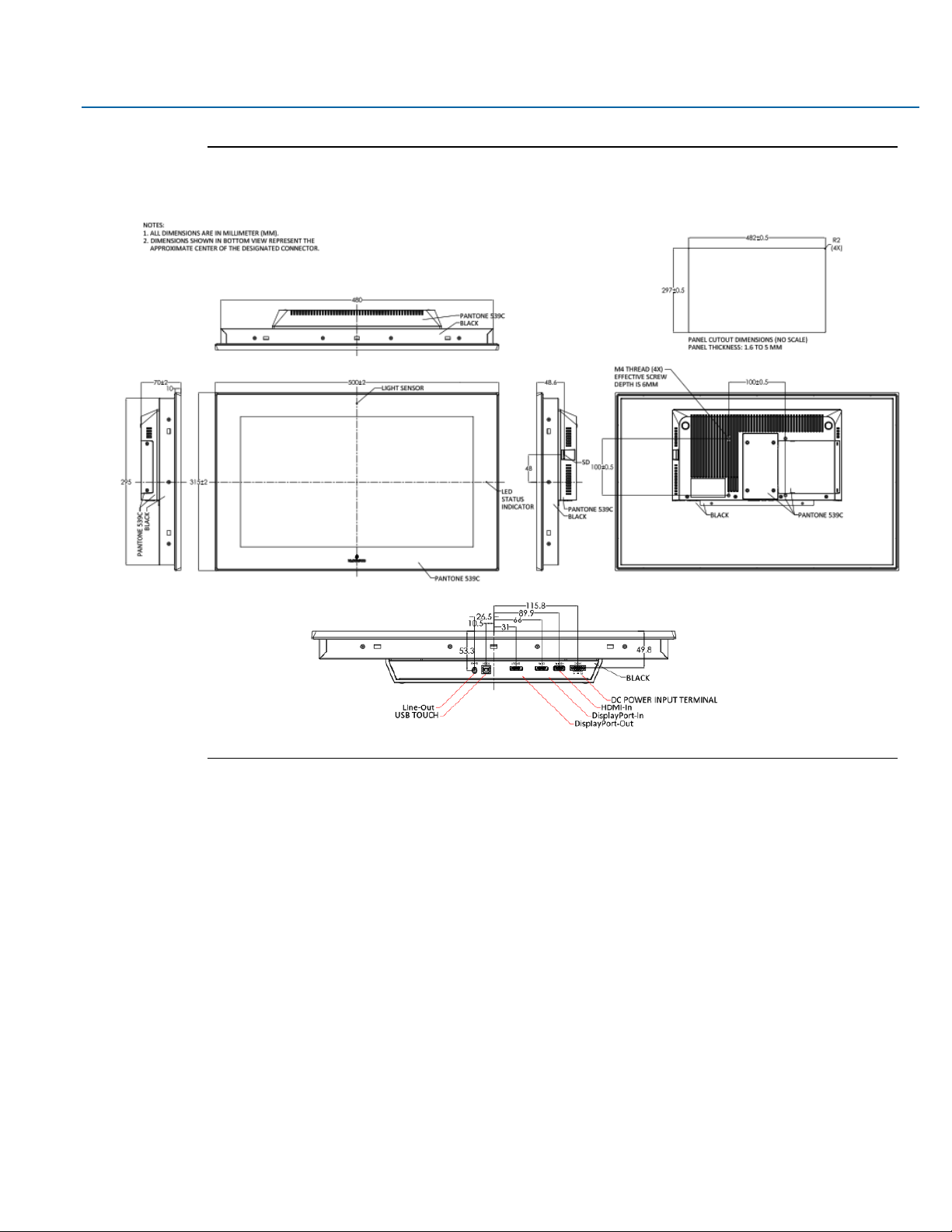
Figure 1.5 Dimensions of 19”
Page 12
User Manual Section 1
GFK-3065 Rev. A May 2019
Getting Started 12
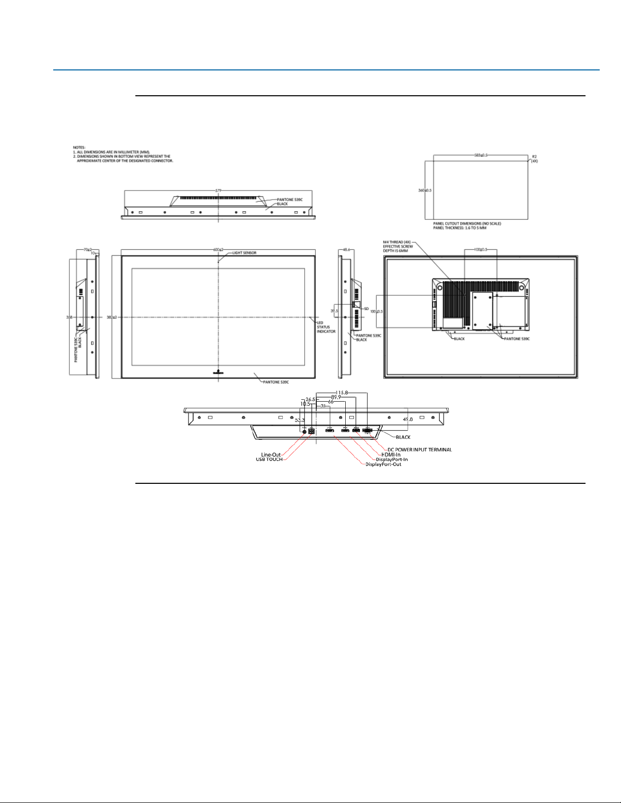
Figure 1.6 Dimensions of 24”
Page 13
User Manual Section 1
GFK-3065 Rev. A May 2019
Getting Started 13
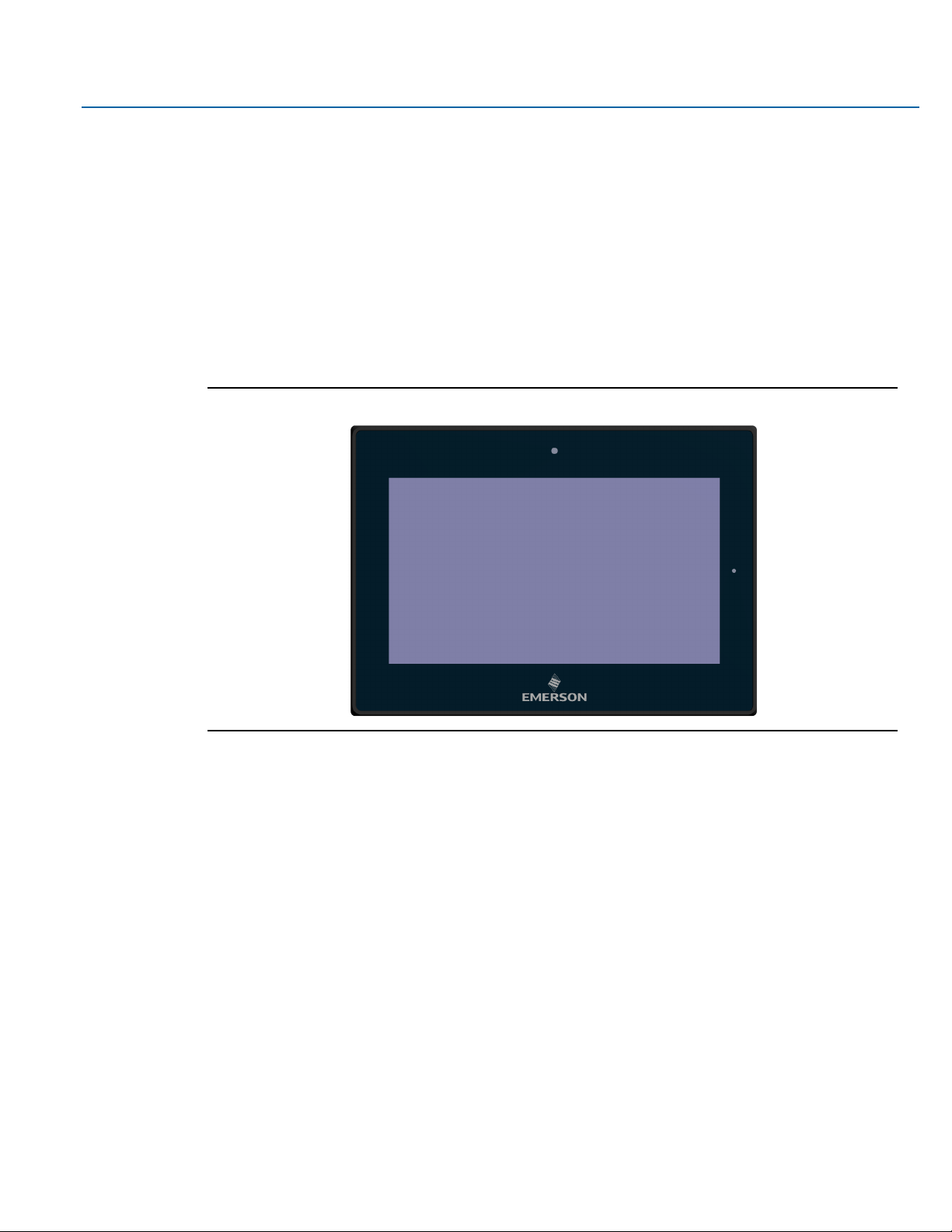
1.4 Brief Description of Industrial Display
The RXi – Industrial Display is an IP66 front bezel aluminum die-cast chassis display, with TFT LCD
widescreen displays sized from 7" to 24". The 1000 nit LCD options are ideal for sunlight readable semi-
outdoor applications and the auto-dimming function allows for dynamic auto-adjustment of the displays for
both day and nighttime use in outdoor applications. The Industrial Monitor series supports DP and HDMI
input, and it can be VESA 100 x 100 mounted. This Industrial display series has even more outstanding
features providing the best in monitoring and control applications.
Figure 1.7 Front View of 7”
Page 14

User Manual Section 1
GFK-3065 Rev. A May 2019
Getting Started 14
Figure 1.8 Front View of 10”
Figure 1.9 Front View of 12”
Page 15

User Manual Section 1
GFK-3065 Rev. A May 2019
Getting Started 15
Figure 1.10 Front View of 15”
Figure 1.11 Front View of 19”
Page 16

User Manual Section 1
GFK-3065 Rev. A May 2019
Getting Started 16
Figure 1.12 Front View of 24”
Figure 1.15 Rear View of 12”
Page 17

User Manual Section 1
GFK-3065 Rev. A May 2019
Getting Started 17
Figure 1.16 Rear View of 15”
Figure 1.17 Rear View of 19”
Page 18

User Manual Section 1
GFK-3065 Rev. A May 2019
Getting Started 18
Figure 1.18 Rear View of 24”
Page 19

User Manual Section 2
GFK-3065 Rev. A May 2019
Hardware 19
Section 2: Hardware
2.1 Motherboard Specifications
Board Size
170 x 113mm
Scalar IC
Realtek RTD2556T-CG
Input
1 x HDMI Input
1 x Display Port (DP) Input (DP1)
1 x USB 2.0 (Type B)
Output
1 x Support up to 24-bit LVDS FULL HD panel interface
1 x Display Port (DP) Output (DP2)
1 x Line-Out (Audio Jack)
Resolution
Up to 1920 x 1080@60Hz for LVDS
Up to 1920 x 1080@60Hz for Display Port
Power Input
DC24V±20%
Temperature
Operating:-20°C to 65°C
Storage:-30°C to 85°C
Humidity
10%-90%, non-condensing, operating
EMI/EMS
Meet CE/FCC class A
Page 20

User Manual Section 2
GFK-3065 Rev. A May 2019
Hardware 20
Figure 2.1 Board Dimensions (mm)
Page 21

User Manual Section 2
GFK-3065 Rev. A May 2019
Hardware 21
2.2 Jumpers and Connectors Location
Figure 2.2 Jumpers and Connectors Location
2.2.1 Connecting Input Power (24V DC-in)
To connect to power, follow these steps:
1. Verify that the power cable is not energized.
2. Loosen the screw clamps on the mating power connector.
3. Strip the insulation from the power cables.
4. Secure the power cable to the mating connector, noting polarity, and tighten the screw clamps. The
torque for the attaching screws is 0.3 Nm (2.26 in-lb).
5. Apply dc power to the unit. During normal startup and operation, the LED status indicator displays as
follows:
• Solid amber while the RXi Industrial Display unit is starting up
• Solid green during normal operation
6. Once power is applied, the unit begins initializing. The first thing to display is the splash screen.
Be sure to connect a DC power cord to this 3-pin power connector. Using a voltage out of the range may fail
to boot the system or cause damage to the system board.
Page 22

User Manual Section 2
GFK-3065 Rev. A May 2019
Hardware 22
2.3 I/O and Connectors
2.3.1 DC_IN1
(3.5mm Pitch 1x3 Pin Connector), DC24V power input connector
Pin #
Power Input
Pin1
DC+24V
Pin2
Ground
Pin3
FG
Page 23

User Manual Section 2
GFK-3065 Rev. A May 2019
Hardware 23
2.3.2 HDMI (HDMI Input)
(HDMI Connector), High Definition Multimedia Interface connector, provide high-quality video and audio
input.
Figure 2.3 HDMI Layout
Signal Name
Pin#
Pin#
Signal Name
DATA2+
1 2 DATA2 Shield
DATA2-
3 4 DATA1+
DATA1 Shield
5 6 DATA1-
DATA0+
7 8 DATA0 Shield
DATA0-
9
10
CLK+
HDMI CAB DET
11
12
CLK-
NC
13
14
NC
HDMI SCL
15
16
HDMI SDA
GND
17
18
HDMI 5V
HDMI HPD
19
Page 24

User Manual Section 2
GFK-3065 Rev. A May 2019
Hardware 24
2.3.3 DP1 (Display Port Input)
(Display Port Connector), Display Port Interface connector, provide high-quality video and audio input.
Signal Name
Pin#
Pin#
Signal Name
LANE3-
1 2 GND
LANE3+
3 4 LANE2-
GND
5 6 LANE2+
LANE1-
7 8 GND
LANE1+
9
10
LANE0-
GND
11
12
LANE0+
GND
13
14
GND
AUX_CHP
15
16
DP CAB DET
AUX_CHN
17
18
DP HPD
RETURN
19
20
DP 3.3V
Page 25

User Manual Section 2
GFK-3065 Rev. A May 2019
Hardware 25
2.3.4 DP2 (Display Port Output)
(Display Port Connector), Display Port Interface connector, provide high-quality video and audio output.
Signal Name
Pin#
Pin#
Signal Name
LANE0+
1 2 GND
LANE0-
3 4 LANE1+
GND
5 6 LANE1-
LANE2+
7 8 GND
LANE2-
9
10
LANE3+
GND
11
12
LANE3-
GND
13
14
GND
AUX_CHP
15
16
GND
AUX_CHN
17
18
DP HPD
RETURN
19
20
DP 3.3V
2.3.5 CN1 (Debug) - Reserved
(2.0mm 1x4 Pin Header), Reserved for debug only.
Pin #
Signal Name
1
3.3V
2
UART TX
3
UART RX
4
GND
Page 26

User Manual Section 2
GFK-3065 Rev. A May 2019
Hardware 26
2.3.6 CN2 - Reserved
(2.0mm 1x4 Pin Header)
Pin #
Signal Name
1
HOST_I2C_SCL
2
HOST_I2C_SDA
3
HOST_IRQ_OUT
4
GND
2.3.7 CN3 - Reserved
(2.0mm 1x4 Pin wafer connector), Reserved for IR receiver
Pin #
Signal Name
1
GND
2
IR
3
3.3V
4
NC
2.3.8 CN4 (OSD)
(2.0mm 1x9 Pin wafer connector), On-Screen Display menu Control connector.
Pin #
Signal Name
1
Power Key
2
R_LED
3
G_LED
4
GND
5
MENU Key
6
DOWN Key
7
UP Key
8
SELECT Key
9
NC
Page 27

User Manual Section 2
GFK-3065 Rev. A May 2019
Hardware 27
2.3.9 CN5 (LVDS Output)
(2.0mm 2x25 Female Pin Header), Connect to TB-572B, providing LVDS, USB, SM BUS and LED signals.
Signal Name
Pin#
Pin#
Signal Name
+12V 1 2
+12V
BackLight Enable
3
4
BackLight CTRL
GND 5 6
GND
Panel 3.3V
7
8
Panel 3.3V
Panel 5V
9
10
Panel 5V
GND
11
12
GND
LVDS Odd0-
13
14
LVDS Odd0+
LVDS Odd1-
15
16
LVDS Odd1+
LVDS Odd2-
17
18
LVDS Odd2+
LVDS Odd CLK-
19
20
LVDS Odd CLK+
LVDS Odd3-
21
22
LVDS Odd3+
LVDS Even0-
23
24
LVDS Even0+
LVDS Even1-
25
26
LVDS Even1+
LVDS Even2-
27
28
LVDS Even2+
LVDS Even CLK-
29
30
LVDS Even CLK+
LVDS Even3-
31
32
LVDS Even3+
GND
33
34
GND
USB D-
35
36
USB 5V
USB D+
37
38
GND
GND
39
40
SM Bus CLK1
5V
41
42
SM Bus Data1
Reserved
43
44
Reserved
GND
45
46
SM Bus CLK2
3.3V
47
48
SM Bus Data2
LED1
49
50
LED2
Page 28

User Manual Section 2
GFK-3065 Rev. A May 2019
Hardware 28
2.3.10 CN6 (USB 2.0)
(2.0mm 1x9 Pin wafer connector), For external USB2.0 signal.
Figure 2.4 USB 2.0
Pin #
Signal Name
1
USB 5V
2
USB-
3
USB+
4
GND
2.3.11 CN7 (Line Out)
(Diameter 3.5mm Jack), Line Out audio port. Line Out can be connected to headphones, speakers or an
amplifier.
Figure 2.5 Line out
Page 29

User Manual Section 2
GFK-3065 Rev. A May 2019
Hardware 29
2.3.12 JP1
(2.0mm Pitch 1x3 Pin Header),
JP1 Pin #
Function
Close 1-2
Backlight Enable & Backlight PWM Level select 3.3V
Close 2-3
Backlight Enable & Backlight PWM Level select 5V
2.3.13 JP2
(2.0mm Pitch 1x3 Pin Header), Backlight control setting.
JP1 Pin #
Function
Close 1-2
For PWM Mode (Default)
Close 2-3
For DC Mode
2.3.14 SW1 - Reserved
Panel Type Select.
2.4 LED Indicators
2.4.1 Operation Status LEDs (Screen)
All RXi Industrial Displays have a tri-color LED built into the screen that provides visual indication of the
operation status.
LED State
System State
Amber, Solid
Operating system starting
Green, Solid
Normal operating state
Green, Blinking
Backlight off
Red, Blinking
Backlight failure
Off
Power not applied to unit
Page 30

User Manual Section 3
GFK-3065 Rev. A May 2019
OSD 30
Section 3: OSD
3.1 AD Board OSD Functions
Figure 3.1 AD Board OSD Functions Legend
Auto Adjust Up/Left Down/Right Power
Menu/Entry Power Indicator
Power switch: To turn ON or OFF the power
Shift the icon to the left side or shift it up
Shift the icon to the right side or shift it down
Menu: To enter OSD menu for related icon and item
Auto Button: One-touch auto adjustment
3.1.1 Enter Burn-in Mode
Before entering burn-in mode, first disconnect the AC power cord, then press and hold the
buttons, then release after the AC power cord is connected and the “RGB” appears on the top left corner of
your screen. Now it can be put into the burn-in mode for changing colors.
Page 31

User Manual Section 3
GFK-3065 Rev. A May 2019
OSD 31
3.1.2 Exit Burn-in Mode
Before exiting burn-in mode, please first disconnect the AC power cord, then press the button (If for any
reason this button is non-functional, press and hold the button) until the AC power cord is connected.
Do not release the button until the AC power cord is connected again and the wording of “RGB” appears on
the top left corner of your screen, then wait for 3 seconds. If there is no input plugged into the unit, the
“CABLE NOT CONNECTED” message will denote that it has successfully left burn-in mode.
3.1.2.1 If unable to exit Burn-in Mode
If the “RGB” is still on the top left corner of the screen, press to enter “Miscellaneous” and choose “Reset”,
and then select “Yes”, and press . When the screen goes black, disconnect power and repeat the above
steps.
If the “RGB” is not found, disconnect the AC power cord first, then press and hold the buttons until
the AC power cord is connected, and wait for 2 to 3 seconds. When “RGB” appears, repeat the above steps.
3.2 OSD Controls
3.2.1 OSD Keypad
To make any adjustment to the settings of the Industrial Monitor, select the following:
1. Press (Menu) to show the OSD menu or dismiss the OSD menu.
2. Select the icon that you wish to adjust with the ( / or +/-) key in the menu.
3. Press (Menu) and then choose the item with the ( / or +/-) key.
4. Press (Menu) and then adjust the quality with the ( / or +/-) key.
Page 32

User Manual Section 3
GFK-3065 Rev. A May 2019
OSD 32
3.2.2 Virtual OSD Keypad
Figure 3.2 Virtual OSD Keyboard
3.3 Main Menu
3.3.1 Picture
Figure 3.3 Picture Menu Options
In the PICTURE menu, there are the following items:
- AutoBacklight
- Backlight
- Brightness
- Contrast
-
Sharpness
Page 33

User Manual Section 3
GFK-3065 Rev. A May 2019
OSD 33
3.3.2 Display
Figure 3.4 Display Menu Options
In the DISPLAY menu, there are the following items:
- AutoAdjust
- H Position
- V Position
-
Disp Rotate
Page 34

User Manual Section 3
GFK-3065 Rev. A May 2019
OSD 34
3.3.3 Color
Figure 3.5 Color Menu Options
In the COLOR menu, there are the following items:
- Panel Uniformity
- Gamma
- Temperature
- Color Effect
Page 35

User Manual Section 3
GFK-3065 Rev. A May 2019
OSD 35
3.3.4 Input
Figure 3.6 Input Menu Options
In the INPUT menu, there are the following items:
- Auto Select
- DP
- HDMI
Page 36

User Manual Section 3
GFK-3065 Rev. A May 2019
OSD 36
3.3.5 Audio
Figure 3.7 Audio Menu Options
In the AUDIO menu, there are the following items:
- Volume
- Mute
Page 37

User Manual Section 3
GFK-3065 Rev. A May 2019
OSD 37
3.3.6 Other
Figure 3.8 Other Menu Options
In the OTHER menu, there are the following items:
- Rest
- Menu Time
- OSD H Position
- OSD V Position
Page 38

User Manual Section 4
GFK-3065 Rev. A May 2019
Mounting Information 38
Section 4: Mounting Information
The Industrial Display series are designed to be panel-mounted or VESA mounted as shown in pictures
below. Carefully place the unit through the hole and tighten the given screws from the rear to secure the
mounting.
4.1 Panel Mount
4.1.1 Installation Steps
1. Verify that the gasket is present and properly seated in the bezel channel located on the sides of the
unit
2. Insert the unit into the mounting panel cutout
Figure 4.1 Panel Install View
3. Insert the hook of the mounting bracket into the mounting hole as displayed in the following figure.
Figure 4.2 Mounting Bracket Insertion
Page 39

User Manual Section 4
GFK-3065 Rev. A May 2019
Mounting Information 39
4. Tighten the screws on the mounting bracket in a clock-wise direction.
Figure 4.3 Tighten Mounting Bracket
4.2 Mounting to Modular Display
Figure 4.4 12” Panel Mount
Page 40

User Manual Section 4
GFK-3065 Rev. A May 2019
Mounting Information 40
Figure 4.5 15” Panel Mount
Figure 4.6 19”/24” Panel Mount
Page 41

User Manual Section 4
GFK-3065 Rev. A May 2019
Mounting Information 41
4.3 VESA Mount
Figure 4.7 10” VESA Mount
Figure 4.8 12” VESA Mount
Page 42

User Manual Section 4
GFK-3065 Rev. A May 2019
Mounting Information 42
Figure 4.9 15” VESA Mount
Figure 4.10 19”/24” VESA Mount
Page 43

Contact Information:
North & South America
18703 GH Circle
PO Box 508
Waller, Texas 77484
USA
T +1 281 727 5300
2500 Park Avenue West
Mansfield, Ohio 44906
USA
T +1 419 529 4311
9009 King Palm Drive
Tampa , Florida 33619
USA
T +1 813 630 2255
4112-91A Street
Edmonton, Alberta T6E5V2
Canada
T +1 780 450 3600
Av. Hollingsworth,325
Iporanga
Sorocaba, SP 18087-105
Brazil
T +55 15 3238 3788
Europe
Asveldweg 11
7556 BT Hengelo(O)
The Netherlands
T +31 74 256 1010
Siemensring 112
D-47877 Willich
Germany
T +49 2154 499 660
30/36 Allee du Plateau
93250 Villemomble
France
T +331 48 122610
6 Bracken Hill
South West Industrial Estate
Peterlee, Co Durham
SR82LS, United Kingdom
T +44 191 518 0020
3 Furze Court
114 Wickham Road
Fareham, Hampshire
PO167SH ,United Kingdom
T +44 132 984 8900
Via Montello 71/73
20038 Seregno
Italy
T +39 0362 2285207
Selska cesta 93
10000 Zagreb
Croatia
T +385 913654292
ul. Konstruktorska str 11A
02-673 Warsaw
Poland
T +48 22 4589237
Hungári körút 166-168
H-1146 Budapest
Hungary
T +36 14624034
Hajkova 2747/22
130 00 Praha 3
Czech Republic
T +42 2 81002666
Zelezniciarska 13
811 04 Bratislava
Slovakia
T +42 1252442071
Blegistrasse 21,
P.O. Box 1046
CH 6341 Baar
Switzerland
T +41 (41) 7686215
2-4, Gara Herastrau St.
District 2, Nova Building,
5th floor 020334 Bucharest
Romania
T +40 212062506
Icerenkoy MAh. Topcu Ibrahim Sk.
No:13 K:4 Icerenkoy
Istanbul, Turkey
T +90 2165739848408
Middle East & Africa
2 Monteer Road, Isando
Kempton Park, 1600
South Africa
T +27 11 974 3336
PO Box 17033
Jebel Ali Free Zone
Dubai,
United Arab Emirates
T +971 4883 5235
Asia Pacific
19, Kian Teck Crescent,
Singapore 628885
T +65 6501 4600
471 Mountain Highway
Bayswater, Victoria 3153
Australia
T +61 3 9721 0200
9/F Gateway Building
No.10 Ya Bao Road
Chaoyang District
Beijing, P.R. China
T +86 10 5821 1188
No 15 Xing Wang Road
Wuqing Development Area
Tianjin 301700
P.R. China
T +86 22 8212 3300
Lot 13112, Mukim Labu,
Kawasan Perindustrian Nilai
71807 Nilai, Negeri Sembilan
Malaysia
T +60 6 799 2323
Delphi B Wing, 601 & 602
6th Floor, Central Avenue
Powai, Mumbai 400076
India
T +91 22 6662 0566
NOF Shinagawa Konan Building
1-2-5, Higashi-shinagawa
Shinagawa-Ku, Tokyo
140-0002 Japan
T +81 3 5769 6873
Please visit our website for up to date product data.
www.Emerson.com
All Rights Reserved.
We reserve the right to modify or improve the designs or specifications of the products mentioned in this manual at any time without notice. Emerson does not
assume responsibility for the selection, use or maintenance of any product. Responsibility for proper selection, use and maintenance of any Emerson product
remains solely with the purchaser.
©2017 Emerson Electric Co.
 Loading...