

Page 1
PACSystems™ RX3i
Input Module, 5/12VDC, Positive/Negative Logic 32 Points, IC694MDL654
GFK-2466 Input Module, 24VDC, Positive/Negative Logic 32 Points, IC694MDL655
January 2010 Input Module, 48VDC, Positive/Negative Logic 32 Points, IC694MDL658
1 2 3 4 5 6 7 8
F
9 10 11 12 13 14 15 16
IC694MDL654
17 18 19 20 21 22 23 24
25 26 27 28 29 30 31 32
INPUT
5/12 VDC
POS/NEG LOGIC
17-32
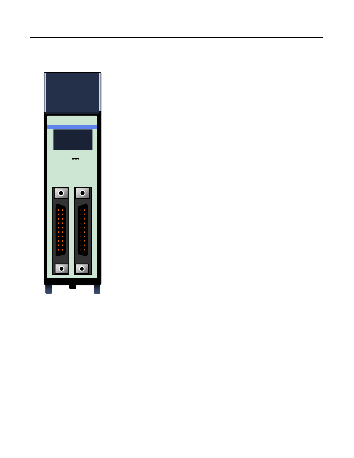
PACSystems RX3i 32-Point Positive/Negative Logic input modules provide 32
positive or negative logic input points in four isolated groups of eight. Each group is
referenced to its own common connection.
5/12VDC (TTL) 32 Point Positive/Negative Logic Input module, IC694MDL654,
shown at left, provides 32 discrete TTL voltage threshold input points that operate
at levels up to 15V. A single, regulated +5V supply (current limited to approximately
150mA) is available through the I/O connectors on the front of the module. This
supply is generated on the module and is isolated from the backplane. Its power
input comes from the +5V logic supply on the PLC backplane. By installing jumpers
on the I/O connector, you can choose to power the inputs from this internal supply
instead of powering them with an external user provided supply.
24VDC 32 Point Positive/Negative Logic Input module, IC694MDL655, provides
1-16
32 discrete input points that operate at levels up to 30V. Power to operate field
devices can come from an external supply or from the module’s isolated +24 VDC
output.
48VDC 32 Point Positive/Negative Logic Input module, IC694MDL658, provides
32 discrete input points that operate at levels up to 60V. Power to operate field
devices must be provided using an external supply.
The blue band on the front label indicates a low-voltage module.
These modules do not report special fault or alarm diagnostics. Green LEDs
indicate the ON/OFF status of each input point.
These modules can be installed in any I/O slot in the RX3i system.
Installation in Hazardous Locations
• EQUIPMENT LABELED WITH REFERENCE TO CLASS I, GROUPS A, B, C & D, DIV. 2 HAZARDOUS
LOCATIONS IS SUITABLE FOR USE IN CLASS I, DIVISION 2, GROUPS A, B, C, D OR NON-HAZARDOUS
LOCATIONS ONLY
• WARNING - EXPLOSION HAZARD - SUBSTITUTION OF COMPONENTS MAY IMPAIR SUITABILITY FOR
CLASS I, DIVISION 2;
• WARNING - EXPLOSION HAZARD - WHEN IN HAZARDOUS LOCATIONS, TURN OFF POWER BEFORE
REPLACING OR WIRING MODULES; AND
• WARNING - EXPLOSION HAZARD - DO NOT DISCONNECT EQUIPMENT UNLESS POWER HAS BEEN
SWITCHED OFF OR THE AREA IS KNOWN TO BE NONHAZARDOUS.
Page 2
2 Input Module, 5/12VDC, Positive/Negative Logic 32 Points, IC694MDL654
Input Module, 24VDC, Positive/Negative Logic 32 Points, IC694MDL655
Input Module, 48VDC, Positive/Negative Logic 32 Points, IC694MDL658
GFK-2466
Specifications
Rated Voltage,
Positive or Negative Logic
Input Voltage Range
Input Current
(typical ON current at rated voltage)
Input Characteristics
On–state Voltage
Off–state Voltage
On–state Current
Off–state Current
On or Off response Time *
Inputs per Module
Isolation:
Field to Backplane
(optical) and to frame ground
Group to Group
Internal Power Consumption
Isolated +5V Supply
Current limit
Refer to the PACSystems RX3i System Manual, GFK-2314, for product standards and general specifications.
IC694MDL654 IC694MDL655 IC694MDL658
5 to12 volts DC
0 to 15 volts DC 0 to 30 volts DC 0 to 60 volts DC
3.0mA @ 5VDC
8.5mA @ 12VDC
4.2 to 15 volts DC 11.5 to 30 volts DC 34 to 60 volts DC
0 to 2.6 volts DC 0 to 5 volts DC 0 to 10 volts DC
2.5mA (minimum)
>
guaranteed on
1.2mA (maximum)
<
guaranteed off
1ms maximum 2ms maximum 2ms maximum
* Within the module; does not include communications with CPU.
32 (four groups of eight inputs each)
98.4 feet (30 meters), maximum cable length for module IC694MDL654.
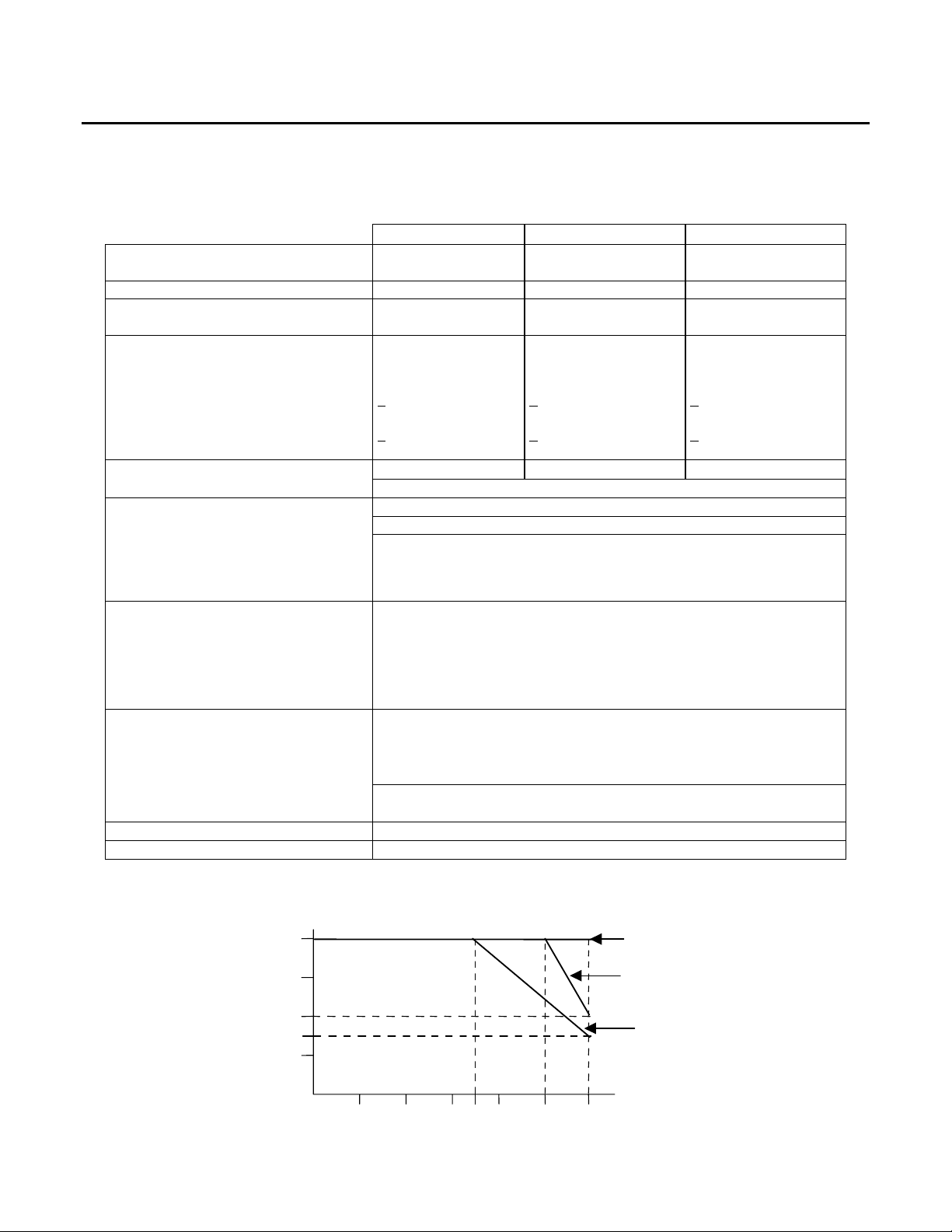
For modules IC694MDL654 and MDL655, the maximum number of inputs
per group that can be on at the same time depends on the ambient
temperature as shown below. There is no thermal derating for module
IC694MDL658.
250 VAC continuous; 1500 VAC for one minute
For modules IC694MDL654 and IC694MDL655, if the 5V OUT / 24V OUT
pin is used to connect to input devices in the field, the isolation is
50 VAC continuous; 500 VAC for one minute.
50 VAC continuous; 500 VAC for one minute
For MDL655, MDL658: 195mA (maximum) from +5V bus on backplane;
(29mA + 0.5mA/point ON + 4.7mA/LED ON)
For MDL654: 440mA (maximum) from +5V bus on backplane (if module
isolated +5V supply used to power inputs and all 32 inputs ON)
For MDL654: 96mA (typical) from user input supply @ 5VDC and 32 inputs
ON); 272mA (typical) from user input supply @ 12VDC and 32 inputs ON)
For MDL654: +5 volts DC +/-5%
For MDL654: 150mA (typical)
24 volts DC 48 volts DC
7.0mA @ 24 VDC 1.7mA @ 48 VDC
>3.2mA (minimum)
guaranteed on
<1.1mA (maximum)
guaranteed off
>1.0mA (minimum)
guaranteed on
<0.4mA (maximum)
guaranteed off
Input Points vs. Temperature
Number of
Inputs per
Group ON
8
6
4
3
2
10°C 20°C 30°C 50°C 60°C
Ambient Temperature (°C)
35°C
40°C
IC694MDL654: 5/12V Supply
IC694MDL654: 15V Supply
IC694MDL655: 24V Supply
IC694MDL655: 30V Supply
Page 3

Input Module, 5/12VDC, Positive/Negative Logic 32 Points, IC694MDL654
+
+
+
+
+
+
T
x
T
Input Module, 24VDC, Positive/Negative Logic 32 Points, IC694MDL655
Input Module, 48VDC, Positive/Negative Logic 32 Points, IC694MDL658 3
GFK-2466
Field Wiring
Connections are made to two male 24–pin connectors (Fujitsu FCN–365P024–AU) on the front of the module. Inputs are
arranged in four groups of eight. Each group has its own common connection. Within each group, four points attach to
the A half of the connector and four points attach to the B half of the connector, as shown below.
IC694MDL654: 5V OUT
IC694MDL655: 24V OUT
IC694MDL658: No Connection
-- +
--
I25
I27
I29
I31
COM
NC
NC
I24
I22
I20
I18
B A
12
11
10
9
8
7
6
5
4
3
2
1
A B
I26
12
I28
11
I30
10
I32
9
NC
8
0V
7
NC
6
--
COM
5
--
I23
4
I21
3
I19
2
I17
1
IC694MDL654/655: 0V
IC694MDL658: No
Connection
--
--
I1
I3
I5
I7
COM
NC
0V
NC
I16
I14
I12
I10
I2
1
1
I4
2
2
I6
3
3
I8
4
4
NC
5
5
6
6
NC
7
7
COM
8
8
I15
9
9
I13
10
10
I11
11
11
I9
12
12
IC694MDL654: 5V OUT
IC694MDL655: 24V OUT
IC694MDL658: No Connection
-- +
--
32-Point Input
Module
Cable 1
Terminal
Block 1
Cable 2
Terminal
Block 2
IC694MDL654: TTL Wiring
Conventional TTL wiring practices should be followed when installing
module IC694MDL654. For noise immunity, I/O control lines connected to
the module must be less than 30 meters in length (signal attenuation limits
wiring length to less than this maximum).To be compatible with TTL
outputs, the negative logic configuration should be used as shown at right.
Wiring from each module connector to
field devices is made through a cable.
Prewired cables are available, or custom
cables can be used. Input devices can
be wired directly to the cables, or to
intermediate Terminal Blocks,
IC693ACC337, as shown here. Please
see Appendix B of the PACSystems
RX3i System Manual, GFK-2314, for
information about prewired cables,
custom cables, and Terminal Block
IC693ACC337.
USER
TTL
5V
IC
OUTPUT
COM
MODULE
INPU
INPUTx
CIRCUI
 Loading...