

Page 1

GE
Intelligent Platforms
Programmable
Control Products
VersaSafe
VersaPoint* Module: IC220SDL953
SAFETY LOGIC MODUL
User‘s Manual, GFK-2731
September 2011
E
, SAFE OUTPUT 24VDC, 8PT
Page 2

This page left blank intentionally
Page 3

User‘s manual
VersaPoint module with integrated safety logic and safe digital outputs
2011-09-29
Catalog No.:
Revision:
This user manual is valid for:
Catalog No. Revision
IC220SDL953 HW/FW/FW: 00/100/100
GFK-2731
03
HW/FW/FW: 00/101/100
Page 4
Please observe the following notes
In order to ensure the safe use of the product described, you have to read and understand
this manual. The following notes provide information on how to use this user manual.
User group of this manual
The use of products described in this manual is oriented exclusively to qualified electricians
or persons instructed by them, who are familiar with applicable national standards and
other regulations regarding electrical engineering and, in particular, the relevant safety
concepts.
GE Intelligent Platforms accepts no liability for erroneous handling or damage to products
from GE Intelligent Platforms or third-party products resulting from disregard of information
contained in this user manual.
Explanation of symbols used and signal words
This is the safety alert symbol. It is used to alert you to potential personal
injury hazards. Obey all safety measures that follow this symbol to avoid
possible injury or death.
DANGER
This indicates a hazardous situation which, if not avoided, will result in death or serious
injury.
WARNING
This indicates a hazardous situation which, if not avoided, could result in death or serious
injury.
CAUTION
This indicates a hazardous situation which, if not avoided, could result in minor or
moderate injury.
The following types of message provide information about possible property damage and
general information concerning proper operation and ease of use.
NOTE
This symbol and the accompanying text alert the reader to a situation which may cause
damage or malfunction to the device, hardware or software, or surrounding property.
This symbol and the accompanying text provide the reader with additional information,
such as tips and advice on the efficient use of hardware and on software optimization. It
is also used as a reference to other sources of information (manuals, data sheets) on the
subject matter, product, etc.
User manual IC220SDL953 - September 2011 GFK-2731
Page 5

General terms and conditions of use for technical documentation
This document is based on information available at the time of its publication. While efforts
have been made to be accurate, the information contained herein does not purport to cover
all details or variations in hardware or software, nor to provide for every possible
contingency in connection with installation, operation, or maintenance. Features may be
described herein which are not present in all hardware and software systems. GE
Intelligent Platforms assumes no obligation of notice to holders of this document with
respect to changes subsequently made.
Statement of legal authority
GE Intelligent Platforms makes no representation or warranty, expressed, implied, or
statutory with respect to, and assumes no responsibility for the accuracy, completeness,
sufficiency, or usefulness of the information contained herein. No warranties of
merchantability or fitness for purpose shall apply.
How to contact us
Internet Up-to-date information on GE Intelligent Platforms products and our Terms and Conditions
can be found on the Internet at:
www.ge-ip.com
Make sure you always use the latest documentation.
It can be downloaded at:
http://support.ge-ip.com
.
.
Subsidiaries If there are any problems that cannot be solved using the documentation, please contact
your GE Intelligent Platforms subsidiary.
.
Published by
Subsidiary contact information is available at www.ge-ip.com
GE Intelligent Platforms. Inc
2500 Austin Dr.
Charlottesville
Virginia
Phone (+1) 800-433-2682
Fax (+1) 780-420-2047
Should you have any suggestions or recommendations for improvement of the contents
and layout of our manuals, please send your comments to:
support.ip@ge.com
* VersaPoint is a trademark of GE Intelligent Platforms, Inc. and/or its affiliates.
All other trademarks are the property of their respective owners.
© Copyright 2011 GE Intelligent Platforms, Inc. All Rights Reserved
GFK-2731
Page 6

User manual IC220SDL953 - September 2011 GFK-2731
This page left blank intentionally
Page 7

Table of contents
1 For your safety..........................................................................................................................1-1
1.1 General safety notes ..........................................................................................1-1
1.2 Electrical safety ..................................................................................................1-2
1.3 Safety of the machine or system........................................................................1-3
1.4 Safety for starting applications ...........................................................................1-4
1.5 Directives and standards....................................................................................1-4
1.6 Correct usage.....................................................................................................1-4
1.7 Documentation ...................................................................................................1-5
1.8 Abbreviations used ...........................................................................................1-5
2 Product description...................................................................................................................2-1
2.1 Note about the system description.....................................................................2-1
2.2 Brief description of the safety module................................................................2-1
2.3 Structure of the safety module ...........................................................................2-2
2.4 Housing dimensions...........................................................................................2-2
2.5 Safe digital outputs.............................................................................................2-3
2.6 Connection options for actuators depending on the parameterization ...............2-5
2.7 Local diagnostic and status indicators ...............................................................2-6
2.8 Safe state ...........................................................................................................2-8
2.8.1 Operating state ...................................................................................2-8
2.8.2 Error detection in I/O devices .............................................................2-8
2.8.3 Device errors ......................................................................................2-9
2.8.4 Parameterization errors ......................................................................2-9
2.9 Process data words..........................................................................................2-10
2.10 Programming data/configuration data ..............................................................2-10
2.10.1 Local bus ..........................................................................................2-10
2.10.2 Other bus systems or networks .......................................................2-10
3 VersaPoint potential and data routing, and VersaPoint connectors .........................................3-1
3.1 VersaPoint potential and data routing ................................................................3-1
3.2 Supply voltage U
3.3 Supply voltage U
3.4 Terminal point assignment .................................................................................3-3
..............................................................................................3-1
L
..............................................................................................3-2
M
4 Assembly, removal, and electrical installation..........................................................................4-1
4.1 Assembly and removal.......................................................................................4-1
4.1.1 Unpacking the module ........................................................................4-1
4.1.2 General ...............................................................................................4-1
4.1.3 Setting the DIP switches .....................................................................4-2
4.1.4 Assembly and removal of the safety module ......................................4-4
GFK-2731 Table of contents i
Page 8

4.2 Electrical installation...........................................................................................4-6
4.2.1 Electrical installation of the VersaPoint station ...................................4-6
4.2.2 Electrical installation of the safety module ..........................................4-6
5 Parameterization of the safety module.....................................................................................5-1
5.1 Parameterization of the safety module in a VersaSafe system.......................... 5-1
5.2 Parameterization of the safe outputs .................................................................5-2
5.3 Behavior of the outputs in the event of enabled switch-off delay for
stop category 1...................................................................................................5-4
6 Connection examples for safe outputs .....................................................................................6-1
6.1 Explanation of the examples ..............................................................................6-1
6.2 Notes on the protective circuit for external relays/contactors
(free running circuit) ...........................................................................................6-2
6.3 Measures required to achieve a specific safety integrity level ...........................6-3
6.4 Single-channel assignment of safe outputs .......................................................6-5
6.5 Two-channel assignment of safe outputs...........................................................6-8
7 Startup and validation...............................................................................................................7-1
7.1 Initial startup.......................................................................................................7-1
7.2 Restart after replacing a safety module .............................................................7-3
7.2.1 Replacing a safety module .................................................................7-3
7.2.2 Restart ................................................................................................7-3
7.3 Validation ...........................................................................................................7-3
8 Errors: Messages and removal.................................................................................................8-1
8.1 Safe digital output errors ....................................................................................8-4
8.2 Supply voltage errors .........................................................................................8-5
8.3 General errors ....................................................................................................8-5
8.4 Parameterization errors......................................................................................8-6
8.5 Connection errors to satellites ..........................................................................8-7
8.6 Acknowledging an error .....................................................................................8-8
9 Maintenance, repair, decommissioning, and disposal..............................................................9-1
9.1 Maintenance.......................................................................................................9-1
9.2 Repair.................................................................................................................9-1
9.3 Decommissioning and disposal..........................................................................9-1
ii User manual IC220SDL953 - September 2011 GFK-2731
Page 9

10 Technical data and ordering data...........................................................................................10-1
10.1 System data .....................................................................................................10-1
10.1.1 VersaPoint ........................................................................................10-1
10.1.2 VersaSafe system ............................................................................10-1
10.2 IC220SDL953...................................................................................................10-1
10.3 Conformance with EMC Directive ....................................................................10-6
10.4 Ordering data ...................................................................................................10-7
10.4.1 Ordering data: Safety module ...........................................................10-7
10.4.2 Ordering data: Accessories ..............................................................10-7
10.4.3 Ordering data: Software ...................................................................10-7
10.4.4 Ordering data: Documentation .........................................................10-7
A Appendix: VersaSafe system .................................................................................................. A-1
A 1 The VersaSafe system..................................................................................... A-1
A 1.1 VersaSafe technology – Maximum flexibility and safety .................... A-1
A 1.2 Overview of VersaSafe system features ........................................... A-2
A 1.3 Differences in VersaSafe systems dependent upon which module
with integrated safety logic is used .................................................... A-2
A 2 System topology............................................................................................... A-4
A 2.1 General topology ............................................................................... A-4
A 2.2 Network and controller requirements ................................................. A-5
A 2.3 Safe input and output devices ........................................................... A-5
A 3 VersaSafe address assignment ...................................................................... A-6
A 4 Operating modes and setting the DIP switches in the VersaSafe system ..... A-10
A 4.1 Module switch positions .................................................................. A-10
A 4.2 VersaSafe multiplexer mode ........................................................... A-11
A 5 Process image ............................................................................................... A-13
A 5.1 Structure of the process image ........................................................ A-13
A 5.2 Description of the registers .............................................................. A-17
A 6 Implementation of data flow between the standard controller and the
safety modules ............................................................................................... A-22
A 6.1 Implementation of data flow with a function block ........................... A-22
A 6.2 Implementation of data flow without a function block ...................... A-22
A 7 Enable principle.............................................................................................. A-22
A 8 Diagnostics..................................................................................................... A-24
A 8.1 Error detection in I/O devices .......................................................... A-24
A 8.2 Detection of device errors ................................................................ A-25
A 8.3 Acknowledgment of error messages for satellites ........................... A-25
A 9 Configuration, parameterization, and download ............................................ A-26
A 9.1 Configuration and parameterization using the VersaConf Safety
tool ................................................................................................... A-26
A 9.2 Downloading the configuration and parameter data record
following power up ........................................................................... A-27
GFK-2731 Table of contents iii
Page 10

A 10 Safe state ....................................................................................................... A-27
A 11 Time response in the VersaSafe system........................................................ A-28
A 11.1 Typical response time ...................................................................... A-28
A 11.2 Shutdown times ............................................................................... A-29
A 12 Achievable safety depending on the modules used ....................................... A-30
A 13 Behavior in the event of an error.................................................................... A-31
A 13.1 Critical system or device errors ....................................................... A-31
A 13.2 Parameterization or configuration errors ......................................... A-32
A 13.3 Communication errors ..................................................................... A-32
A 13.4 I/O errors ......................................................................................... A-32
A 14 Startup and restart ......................................................................................... A-33
A 14.1 Startup/restart following power up ................................................... A-33
A 14.2 Restart after triggering a safety function .......................................... A-33
A 15 Memory sizes for the safety logic................................................................... A-33
B Appendix: Checklists ............................................................................................................... B-1
B 1 Checklists for the VersaSafe system................................................................ B-2
B 1.1 Planning .................................................................................... B-2
B 1.2 Configuration and parameterization ......................................... B-4
B 1.3 Startup ...................................................................................... B-5
B 1.4 Safety functions ................................................................................. B-6
B 1.5 Validation .................................................................................. B-7
B 2 Checklists for the
IC220SDL953 module ...................................................................................... B-8
B 2.1 Planning ..................................................................................... B-8
B 2.2 Assembly and electrical installation ............................................. B-9
B 2.3 Startup ........................................................................................ B-10
B 2.4 Validation ....................................................................................... B-11
C Index........................................................................................................................................ C-1
iv User manual IC220SDL953 - September 2011 GFK-2731
Page 11
1 For your safety
Purpose of this manual
The information in this document is designed to familiarize you with how the IC220SDL953
safety module works, its operating and connection elements, and its parameter settings.
This information will enable you to use the module within a VersaSafe system according to
your requirements.
Validity of the user manual
This manual is only valid for the IC220SDL953 module in the version indicated on the inner
cover page.
1.1 General safety notes
WARNING: Depending on the application, incorrect handling of the safety module
can pose serious risks for the user
When working with the safety module within the VersaSafesystem, please observe all
the safety notes included in this section.
1
Requirements Knowledge of the following is required:
– The target system (e.g., PROFIBUS, PROFINET)
– The standard control system
– The VersaSafe system (see Appendix A)
– The components used in your application
– The VersaPoint product range
– Operation of the software tools used
– Safety regulations in the field of application
Qualified personnel In the context of the use of the VersaSafe system, the following operations may only be
carried out by qualified personnel:
– Planning
– Configuration of the safety logic and parameterization
– Installation, startup, servicing
– Maintenance, decommissioning
This user manual is, therefore, aimed at:
– Qualified personnel who plan and design safety equipment for machines and systems
and are familiar with regulations governing safety in the workplace and accident
prevention
– Qualified personnel who install and operate safety equipment in machines and
systems
In terms of the safety notes in this manual, qualified personnel are persons who, because
of their education, experience and instruction, and their knowledge of relevant standards,
regulations, accident prevention, and service conditions, have been authorized to carry out
any required operations, and who are able to recognize and avoid any possible dangers.
GFK-2731 Chapter 1 For your safety 1-1
Page 12

1
Documentation You must observe all information in this manual as well as in the documents listed in
"Documentation" on page 1-5.
Safety of personnel and
equipment
Error detection Depending on the wiring and the corresponding setting of the safe output module
Do not carry out any
repairs
Do not open the
housing/security seal
Measures to prevent
incorrect connection and
polarity reversal
The safety of personnel and equipment can only be assured if the safety module is used
correctly (see "Correct usage" on page 1-4).
parameters, the VersaSafe system can detect various errors within the safety equipment.
Repair work may not be carried out on the safety module.
In the event that an error cannot be removed, please contact GE Intelligent Platforms
immediately, engage a service engineer, or send the faulty module directly to GE Intelligent
Platforms.
It is strictly prohibited to open the safety module housing. In order to prevent the
manipulation of the safety module and to detect the unauthorized opening of the safety
module, a security seal is applied to the module. This security seal is damaged in the event
of unauthorized opening. In this case, the correct operation of the safety module can no
longer be ensured.
Take measures to prevent the incorrect connection, polarity reversal, and manipulation of
connections.
1.2 Electrical safety
WARNING: Hazardous body currents and the loss of functional safety
Disregarding instructions for electrical safety may result in hazardous body currents and
the loss of functional safety.
In order to ensure electrical safety, please observe the following points.
Direct/indirect contact Ensure that all components connected to the system are protected against direct and
indirect contact according to VDE 0100 Part 410. In the event of an error, parasitic voltages
must not occur (single-fault tolerance).
This can be achieved by:
– Using power supply units with safe isolation (PELV).
– Decoupling circuits, which are not SELV or PELV systems, using optocouplers, relays,
and other components meeting the requirements of safe isolation.
Power supply unit for 24 V
supply
1-2 User manual IC220SDL953 - September 2011 GFK-2731
Only use power supply units with safe isolation and PELV according to
EN 50178/VDE 0160 (PELV). This prevents short circuits between primary and secondary
sides.
Make sure that the output voltage of the power supply does not exceed 32 V even in the
event of an error.
Page 13
1
Insulation rating When selecting the operating equipment, please take into consideration the contamination
and surge voltages, which may occur during operation.
The IC220SDL953 module is designed for surge voltage category II (according to
DIN EN 60664-1). If you expect surge voltages in the system, which exceed the values defined in surge voltage category II, take into consideration additional measures for voltage
limitation.
Installation and
configuration
Draw up and implement a
safety concept
Please observe the instructions for installing and configuring the system (see
"Documentation" on page 1-5).
WARNING: Depending on the application, incorrect installation and upgrades can
pose serious risks for the user
The user is obliged to design the devices used and their installation in the system
according to these requirements. This also means that existing plants and systems
retrofitted with the VersaSafe system must be checked and tested again in this respect.
1.3 Safety of the machine or system
The machine/system manufacturer and the operator are solely responsible for the safety
of the machine or system and the implemented application, in which the machine or system
is used. The Machinery Directive must be observed.
In order to use the safety module described in this document, you must have drawn up an
appropriate safety concept for your machine or system. This includes a hazard and risk
analysis according to the directives and standards specified in "Directives and standards"
on page 1-4, as well as a test report (checklist) for validating the safety function (see
"Appendix: Checklists" on page B-1).
The target safety integrity level (SIL according to EN 61508, SIL CL according to EN 62061
or performance level and category according to EN ISO 13849-1) is ascertained on the
basis of the risk analysis. The safety integrity level ascertained determines how to connect
and parameterize the safety module within the overall safety function.
Within a VersaSafe system, the IC220SDL953 safety module can be used to achieve
safety functions with the following requirements depending on the conditions of use:
– Up to SIL 3 according to standard EN 61508
– Up to SIL CL 3 according to standard EN 62061
– Up to Cat. 4/PL e according to standard EN ISO 13849-1
Please also refer to "Achievable safety depending on the modules used" on page A-30.
Check hardware and
parameterization
GFK-2731 Chapter 1 For your safety 1-3
Carry out a validation every time you make a safety-related modification to your overall
system.
Use your test report to ensure that:
– The safe devices are connected to the correct safe sensors and actuators
– The safe input and output devices have been parameterized correctly
– The safety functions have been wired correctly
Page 14

1
1.4 Safety for starting applications
Consider your machine or system when determining the start conditions:
– Starting the machine or system may only take place when no persons are within the
danger zone.
– Comply with the requirements of EN ISO 13849-1 with respect to manual resetting
functions.
This applies to:
– Switching on of safe devices.
– Acknowledgment of device error messages.
– Acknowledgment of communication errors.
– Acknowledgment of block error messages in the application.
– Removing safeguards for safety functions.
Observe your safety logic during programming/configuring:
– The change from a safe state (replacement value = 0) to the operating state can cause
an edge change (zero-one-edge).
– Include measures in your safety logic that prevent this edge from starting or restarting
of the machine/system unexpectedly.
1.5 Directives and standards
The manufacturers and operators of machines and systems, in which the IC220SDL953
module is used, are responsible for adhering to all applicable directives and legislation.
For the standards observed by the module, please refer to the certificate issued by the
approval body and the EC declaration of conformity. These documents are available on the
Internet at www.ge-ip.com
.
1.6 Correct usage
Only use the VersaSafe system in accordance with the instructions in this section.
The IC220SDL953 safety module is designed exclusively for use in a VersaSafe system.
It can only perform its safety-related tasks within the system if it has been integrated into
the execution process correctly and in such a way as to avoid errors.
You must observe all information in this manual as well as in the documents listed in
"Documentation" on page 1-5. In particular, only use the module according to the technical
data and ambient conditions specified in Section 10, "Technical data and ordering data" on
page 10-1 and onwards.
Within a VersaSafe system, the safety module can be used to achieve safety functions with
the following requirements depending on the conditions of use:
– Up to SIL 3 according to standard EN 61508
– Up to SIL CL 3 according to standard EN 62061
– Up to Cat. 4/PL e according to standard EN ISO 13849-1
Please also refer to "Achievable safety depending on the modules used" on page A-30.
1-4 User manual IC220SDL953 - September 2011 GFK-2731
Page 15
1
The safety module is designed for connecting single-channel or two-channel actuators,
which can be used in association with safety technology.
For example, the module can be used in the following applications:
– Safety circuits according to EN 60204 Part 1
– Safe shutdown of contactors, motors (24 V DC), valves, ohmic, inductive, and
capacitive loads
The module is not suitable for applications in which stop category 1 also has to be
observed in the event of an error (see also "Behavior of the outputs in the event of enabled
switch-off delay for stop category 1" on page 5-4).
1.7 Documentation
Latest documentation Make sure you always use the latest documentation. Changes or additions to this
document can be found on the Internet at http://support.ge-ip.com.
VersaSafe system When working on the VersaSafe system and its components, you must always keep this
user manual and other items of product documentation to hand and observe the
information therein.
User manuals:
– For the controller used
– For VersaSafe system I/O modules
– For VersaSafe system function blocks
Please also observe the relevant information about the bus system used.
VersaPoint product range GFK-2736
Automation terminals of the VersaPoint product range (configuration and installation)
Documentation for the
1.8 Abbreviations used
Table 1-1 Abbreviations used
Abbreviation
SIL Safety integrity level EN 61508 SIL 2, SIL 3
SIL CL SIL claim limit EN 62061 SIL CL 3
Cat. Category EN ISO 13849-1 Cat. 2, Cat. 4
PL Performance level EN ISO 13849-1 PL e, PL d
Network Interface Unit (NIU) used
Meaning Standard Example
GFK-2731 Chapter 1 For your safety 1-5
Page 16
1
Table 1-2 Abbreviations used
Abbreviation
PELV Protective extra-low voltage
EUC Equipment under control
Meaning
A circuit in which the voltage does not exceed 30 V AC, 42.4 V peak
value or 60 V DC under normal conditions or single-fault conditions, except in the event of grounding errors in other circuits.
A PELV circuit is like a SELV circuit, but is connected to protective earth
ground.
(According to EN 61131-2)
1-6 User manual IC220SDL953 - September 2011 GFK-2731
Page 17
2 Product description
2.1 Note about the system description
The VersaSafe system is described in "Appendix: VersaSafe system" on page A-1.
In the description of the IC220SDL953 safety module, it is assumed that you are familiar
with the VersaSafe system. If this is not the case, please refer to "Appendix: VersaSafe
system" on page A-1 first for information about the system.
2.2 Brief description of the safety module
The IC220SDL953 module is designed for use within a VersaPoint station. The module
features integrated configurable safety logic and safe digital outputs.
The IC220SDL953 safety module can be used as part of a VersaPoint station at any point
within a VersaSafe system.
The transmission speed of the VersaPoint local bus can be set to 500 kbaud or 2 Mbaud
on the safety module using switches.
Use the same transmission speed throughout a VersaPoint station.
The module has a 10-pos. DIP switch, which is used to set the island number and
operating mode.
The module has four safe positive switching digital outputs for two-channel assignment or
eight safe positive switching digital outputs for single-channel assignment.
The outputs can be parameterized according to the application. The outputs enable
actuators to be integrated into the VersaSafe system.
Within a VersaSafe system, the IC220SDL953 safety module can be used to achieve
safety functions with the following requirements:
– Up to SIL 3 according to standard EN 61508
– Up to SIL CL 3 according to standard EN 62061
– Up to Cat. 4/PL e according to standard EN ISO 13849-1
2
Please also refer to "Achievable safety depending on the modules used" on page A-30.
GFK-2731 Chapter 2 Product description 2-1
Page 18
2
4x
4x
1
2
3
7
8
9
1
2
0
1
2
1
1
2
2
1
2
3
D
6
79690002
FS
UM
9
8
7
6
5
4
3
2
1
0
4
5
P
79690008
48,8
71,5
119,8
9
8
7
6
5
4
3
2
1
0
off
on
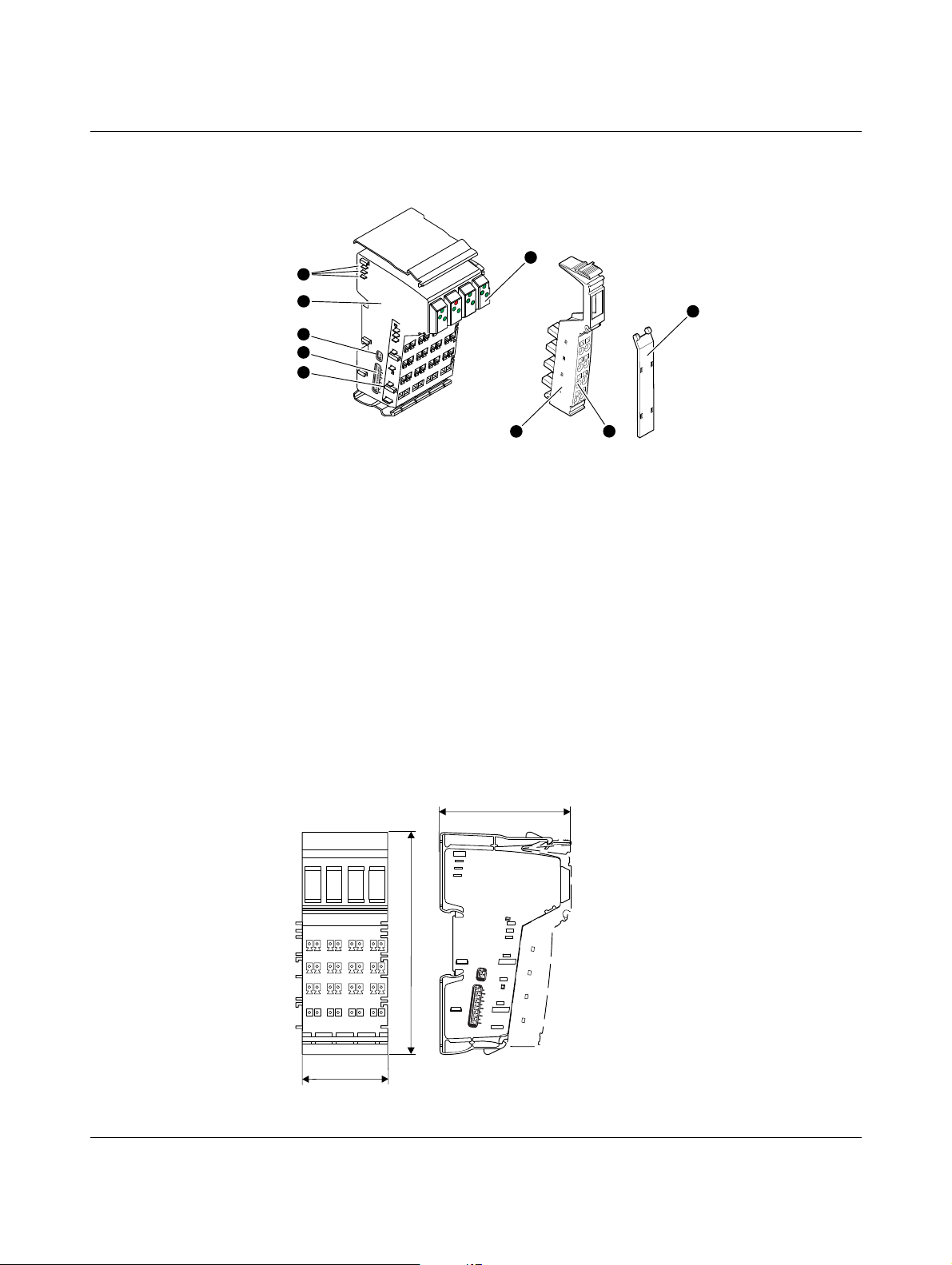
2.3 Structure of the safety module
Figure 2-1 Structure of the safety module
1 Data jumpers (local bus)
2 Electronics base with labeling including version designation
hardware/firmware/firmware (not shown)
3 Switch for setting the transmission speed and operating mode
4 Switch for setting the address
5 Potential jumper
6 Diagnostic and status indicators; for assignment and meaning see "Local diagnostic
and status indicators" on page 2-6
7 VersaPoint connector; for assignment see "Terminal point assignment" on page 3-3
8 Terminal points
9 Labeling field
2.4 Housing dimensions
2-2 User manual IC220SDL953 - September 2011 GFK-2731
Figure 2-2 Housing dimensions (in mm)
Page 19

2
2.5 Safe digital outputs
The safety module has safe positive switching digital outputs, which can be used as follows:
– For two-channel assignment:
– Four two-channel outputs
– For single-channel assignment:
– Eight single-channel outputs
Technical data For the technical data for the safe outputs, please refer to page 10-4.
Parameterization The individual safe digital outputs of a safety module can be parameterized differently. This
means that the outputs can be adapted to various operating conditions and different safety
integrity levels (SIL, SIL CL, Cat., PL) can be implemented.
In order to achieve a high level of error detection, the test pulses must be enabled. If this
is not possible for the connected loads, the test pulses can be disabled. However, in this
case error detection is reduced.
The safety integrity level (SIL, SIL CL, Cat., PL) and error detection that can be achieved
depend on the parameterization, the structure of the actuator, and the cable installation
(see "Connection examples for safe outputs" on page 6-1).
For information about parameterization, please refer to "Parameterization of the safe
outputs" on page 5-2.
Diagnostics Diagnostics are provided via both the local diagnostic indicators and the diagnostic
messages, which are transmitted to the controller.
For information about the diagnostic messages of the outputs, please refer to "Safe digital
output errors" on page 8-4.
CAUTION: Diagnostic data is not safety-related
The diagnostic data is not safety-related. This data must not be used to execute safetyrelated functions or actions.
GFK-2731 Chapter 2 Product description 2-3
Page 20
2
Requirements for controlled devices/actuators
The error detection of the module varies depending on the parameterization. This results
in specific requirements for the actuators.
– If the outputs are parameterized with test pulses, the output circuits are tested by test
pulses at regular intervals. These test pulses are visible at the output and can trigger
undesirable reactions with quick responding actuators.
WARNING: Unintentional machine startup
If the process does not tolerate this behavior, actuators with sufficient inertia must
be used.
In general, the load must not be so dynamic that it causes dangerous states within
1ms.
Quick actuators, which offer a safety-related response to pulses in under 1 ms, may
not generally be used.
Switching off the test pulses affects the error detection of the module. Please observe
the achievable safety integrity level, which is specified in "Connection examples for
safe outputs" on page 6-1.
The failure detection time is 20 ms.
Please refer to "Single-channel assignment of safe outputs" on page 6-5 and "Twochannel assignment of safe outputs" on page 6-8 for additional information.
– Only use appropriately qualified actuators.
– Use reliable components. These include, for example:
– Control contactors according to EN 60947-4-1
– Power contactors
– Relays with positively driven contacts according to DIN EN 50205
– Use relays or contactors with positively driven N/C contacts to safely monitor the state
(pick-up, drop-out).
– Please observe any special environmental requirements in your application when
selecting the controlled devices.
– Please note applicable C standards in your application (e.g., EN 1010), in which, for
example, the number of controlled devices required to achieve a particular category is
specified.
2-4 User manual IC220SDL953 - September 2011 GFK-2731
Page 21
2
2.6 Connection options for actuators depending on the
parameterization
Actuators that meet various safety requirements depending on the parameterization can
be connected to the outputs. For connection examples, please refer to Section 6,
"Connection examples for safe outputs".
The maximum achievable SIL/SIL CL/Cat./PL is specified in the table.
In order to achieve this:
– Observe the information in the connection examples (see Section 6, "Connection
examples for safe outputs")
– Observe the requirements of the standards with regard to the external wiring and the
actuators to be used to achieve a SIL/SIL CL/Cat./PL (see "Measures required to
achieve a specific safety integrity level" on page 6-3)
Output OUT0 to OUT3
"Output" parameterization
Test pulses Any ON/OFF*
Achievable category SIL 2/SIL CL 2/Cat. 3/PL d SIL 3/SIL CL 3/Cat. 4/PL e
For connection example, see
page
Key:
Single-channel Two-channel
6-5 6-8
* If the test pulses are disabled, a cross circuit between the outputs is only detected
if the output is enabled.
To achieve Cat. 3, two-channel actuators are usually used.
GFK-2731 Chapter 2 Product description 2-5
Page 22

2
1
2
LPSDO8
0
1
2
1
1
2
2
1
2
3
D
FS
UM
79690003
D
LPSDO8
1
2
1
2
1
2
1
2
FS
UM
0
1
2
3
9
8
7
6
5
4
3
2
1
0
P
P
Observe the module startup time of approximately 16 s. During this time the D LED flashes at
4 Hz and the bus cannot be started up.
Do not start to download the configuration and parameter data record until the firmware has
started up (approx. 16 s; bit SA = 1 in Dev-Reg-LPSDO; see Appendix A 5.2 on page A-17).
2.7 Local diagnostic and status indicators
Figure 2-3 Local diagnostic and status indicators of the IC220SDL953 module
Table 2-1 Local diagnostic and status indicators
D Green LED Diagnostics
OFF: Communications power is not present
Flashing at 0.5 Hz: Communications power present, local bus not active
Flashing at 4 Hz: Communications power present, error at the interface between previous and flashing
terminal (the terminals after the flashing terminal cannot be addressed).
(E.g., loose contact at the bus interface, terminal before the flashing terminal has
failed, another terminal was snapped on during operation (not permitted))
ON: Communications power present, local bus active
FS Red LED Failure state
Flashing at 1 Hz: Device not parameterized or parameterization was not accepted
ON: Hardware fault
The output drivers are reset, there is no communication to the satellites
Or:
Impermissible switch position
The module will respond to certain impermissible switch positions by entering the
failure state immediately after power up.
2-6 User manual IC220SDL953 - September 2011 GFK-2731
Page 23
Table 2-1 Local diagnostic and status indicators (continued)
In the event of an error (red LED ON), the output is switched off until the acknowledgment sent
by the controller is received by the safety module (see also "Safe digital output errors" on
page 8-4).
2
UM Green LED Monitoring the supply voltage U
OFF: Communications power is not present
Flashing at 1 Hz: U
ON: U
P Green LED Status indicator for communication
OFF: IC220SDL953 not parameterized
Flashing at 0.5 Hz: IC220SDL953 is parameterized, but safe communication is not running to at least
ON: Communication OK
OUT
0.1 - 3.2
Green/red LED Status of each output
Green: Output at logic 1
OFF: Output at logic 0, no error
Red ON: Short circuit/overload of an output
below the permissible voltage range (undervoltage)
M
present
M
one satellite
IC220SDL953 is parameterized and safe communication is running without any
errors to all configured satellites.
If no satellites have been configured: IC220SDL953 is parameterized.
Corresponds to COK bit = 1 (see "Dev-Diag-LPSDO (LPSDO diagnostics)" on
page A-18)
(see "Terminal point assignment" on page 3-3)
(This diagnostic message is stored temporarily on the module. The message is
stored in the volatile memory and will be lost after a voltage reset.)
M
GFK-2731 Chapter 2 Product description 2-7
Page 24

2
2.8 Safe state
The safe state for the module is the low state at the output terminals (see "Safe digital
outputs" on page 2-3).
The safe state can be entered in the following cases:
1. Operating state
2. Error detection in I/O devices
3. Device errors
4. Parameterization errors
2.8.1 Operating state
In the operating state, the outputs can enter states "1" or "0". In general, state "0" is the
safe state.
WARNING: Loss of the safety function possible due to undetected accumulation
of errors
Also evaluate the diagnostics of modules that are not used, but are connected to the
power supply, at regular intervals or disconnect these modules from the supply voltage.
2.8.2 Error detection in I/O devices
Outputs If an error is detected at an output, the affected output is disabled ("0" = OFF = safe state).
Depending on the parameterization, the following errors can be detected at outputs:
– Short circuit
– Cross circuit
– Overload
The relevant diagnostic message is transmitted to the controller (see "Safe digital output
errors" on page 8-4). For information about which errors are detected and when, please
refer to "Connection examples for safe outputs" on page 6-1.
If an error occurs on a channel of an output parameterized as "two-channel", the other
corresponding channel also enters the safe state.
2-8 User manual IC220SDL953 - September 2011 GFK-2731
Page 25

2
2.8.3 Device errors
Outputs If a hardware fault in the internal circuit is detected at an output, all module outputs are
disabled ("0" = OFF = safe state).
The relevant diagnostic message is transmitted to the controller (see "Safe digital output
errors" on page 8-4).
Serious errors All serious errors that can result in the loss of or adversely affect the safety function cause
the entire module to enter the safe state. The FS LED on the safety module is permanently
on.
The following errors result in the safe state:
– Serious hardware faults in the internal circuit
– User errors
– Module overload
– Module overheating
– Faulty supply voltage
– Impermissible switch position, DIP switches
The relevant diagnostic message is transmitted to the controller (see "Errors: Messages
and removal" on page 8-1).
WARNING: Loss of the safety function due to sequential errors
In the event of a device error, the following measures should be taken to prevent
sequential errors:
Disconnect the module from the power supply and replace it.
2.8.4 Parameterization errors
Parameterization errors are indicated:
– As long as the module is not parameterized
or
– In the event of faulty parameterization
Parameterization errors cause the entire module to enter the safe state. The FS LED on
the safety module flashes.
In the event of faulty parameterization, the relevant diagnostic message is transmitted to
the controller (see "Parameterization errors" on page 8-6).
Exception:
If an output is operated in stop category 1 and this output is within the switch-off delay
time, then another instance of faulty parameterization results in the entire module
switching to the safe state only once the switch-off delay time has elapsed.
GFK-2731 Chapter 2 Product description 2-9
Page 26

2
2.9 Process data words
The module uses 8, 16, or 24 words in the VersaPoint system. How these words are
mapped is described in "Process image" on page A-13.
The input data only indicates the actual status of the outputs if no bus errors or device
errors are present. Even during the parameterized switch-off delay in stop category 1, the
status of the outputs on the module does not correspond to the status of the outputs on the
controller.
The parameterization of the outputs determines whether the input data is mapped in
single-channel or two-channel mode. The value for "parameterized output" for the outputs
is also set for the input data.
2.10 Programming data/configuration data
2.10.1 Local bus
Operating mode VersaSafe
24 words
ID code ABhex (171dec) AB
Length code 18
Input address area Application-specific Application-specific Application-specific
Output address area Application-specific Application-specific Application-specific
Parameter channel (PCP) 0 words 0 words 0 words
Register length 24 words 16 words 8 words
(24dec) 10
hex
2.10.2 Other bus systems or networks
The programming data/configuration data is defined in the device description (FDCML,
GSD, GSDML, etc.) according to the bus or network used.
VersaSafe
16 words
(171
hex
(16
hex
VersaSafe multiplexer
)AB
dec
)08
dec
hex
(08dec)
hex
(171
dec
)
2-10 User manual IC220SDL953 - September 2011 GFK-2731
Page 27
3 VersaPoint potential and data routing, and VersaPoint
connectors
3.1 VersaPoint potential and data routing
For operation, the safety module must be integrated in a VersaPoint station within the VersaSafe system.
The bus signals are transmitted via the VersaPoint data jumpers. The required supply voltages are transmitted via the VersaPoint potential jumpers.
For more detailed information about potential and data routing within a VersaPoint station, please refer to the GFK-2736 user manual.
The segment circuit is looped through the safety module and is available again after the
module. The segment circuit cannot be accessed in the safety module.
3
3.2 Supply voltage U
Feed in the 24 V supply voltage UBK/U
The 7.5 V voltage UL is generated from this 24 V supply voltage in the bus coupler or power
terminal. It is made available to the safety module via the VersaPoint potential jumper UL.
WARNING: Loss of the safety function when using unsuitable power supplies
For the voltage supply at the bus coupler or power terminal, please note:
Only power supplies according to EN 50178/VDE 0160 (PELV) may be used.
Please also observe the points in "Electrical safety" on page 1-2.
The supply voltage U
power. For technical data for the supply voltage UL, please refer to "Supply voltage UL
(logic)" on page 10-3.
The maximum current carrying capacity for the supply voltage UL is 2 A.
This current carrying capacity can be reduced if certain terminals are used. Please refer to
the information in the terminal-specific data sheets.
is used to supply the bus controller board and the communications
L
L
at a bus coupler or a suitable power terminal.
24V
GFK-2731 Chapter 3 VersaPoint poten tial and data routing, and VersaPoint connectors 3-1
Page 28

3
3.3 Supply voltage U
M
Feed in the supply voltage at a bus coupler or a power terminal. It is made available to the
safety module via the VersaPoint potential jumper U
.
M
WARNING: Loss of the safety function when using unsuitable power supplies
For the voltage supply at the bus coupler or power terminal, please note:
Only power supplies according to EN 50178/VDE 0160 (PELV) may be used.
Please also observe the points in "Electrical safety" on page 1-2.
The supply voltage U
ply voltage U
, please refer to "Supply voltage UM (actuators)" on page 10-3.
M
The maximum current carrying capacity for the main circuit U
is used to supply the output circuits. For technical data for the sup-
M
is 8 A (total current with the
M
segment circuit that is not used in the safety terminal). This current carrying capacity can
be reduced if certain terminals are used. Please refer to the information in the terminal-specific data sheets.
If the limit value of the potential jumpers U
and US is reached (total current of US and UM),
M
a new power terminal must be used.
NOTE: Module damage due to polarity reversal
Polarity reversal places a burden on the electronics and, despite protection against
polarity reversal, can damage the module. Therefore, polarity reversal must be
prevented.
For the behavior of the safety module in the event of an error at the supply voltage, please
refer to "Supply voltage errors" on page 8-5.
U für Einspeisung am Buskoppler
US for supply at a bus coupler or a power
S
oder einer Einspeiseklemme (wird in der
terminal (not required in the safety terminal)
Sicherheitsklemme nicht benötigt)
U für Einspeisung am Buskoppler
UM for supply at a bus coupler or a
M
oder einer Einspeiseklemme
power terminal
230 V
24 V
24 V DC
(PELV)
+
External fuse
externe Sicherung
8 A, maximum
max. 8 A
-
GND for supply at a bus coupler or a
GND der Einspeisung am Buskoppler
power terminal
Figure 3-1 Supply U
oder einer e
with connection to functional earth ground according to
M
76191004
60204-1
WARNING: Loss of functional safety due to parasitic voltages
Feed in the supply voltages U
and US at a bus coupler and/or a power terminal from
M
the same power supply unit, so that the loads of IC220SDL953 are not affected by parasitic voltages in the event of an error.
3-2 User manual IC220SDL953 - September 2011 GFK-2731
Page 29

3
73410004
12
1.1
1.2
1.3
1.4
2.1
2.2
2.3
2.4
12
3.1
3.2
3.3
3.4
4.1
4.2
4.3
4.4
12
5.1
5.2
5.3
5.4
6.1
6.2
6.3
6.4
12
7.1
7.2
7.3
7.4
8.1
8.2
8.3
8.4
1
2
3
4
1
2
3
4
1
2
3
4
1
2
3
4
1
2
3
4
1
2
3
4
1
2
3
4
1
2
3
4
1.1
1.2
1.3
1.4
8.1
8.3
8.4
8.2
NOTE: Damage to module electronics in the event of surge voltage
Do not use a DC distribution network.
DC distribution network according to IEC 61326-3-1:
A DC distribution network is a DC power supply network, which supplies a complete
industrial hall with DC voltage and to which any device can be connected. A typical system
or machine distribution is not a DC distribution network. For devices that are provided for
a typical system or machine distribution, the DC connections are viewed and tested as I/O
signals according to IEC 61326-3-1.
3.4 Terminal point assignment
Figure 3-2 Terminal point assignment
The VersaPoint connectors are supplied with the module. They are keyed and labeled
accordingly for connection to prevent polarity reversal. If other connectors are used
according to the ordering data, they must also be keyed.
Only use the connectors supplied with the module or connectors that are approved as
replacement items (see "Ordering data: Accessories" on page 10-7).
The following applies for the tables below:
– All outputs are safe digital outputs
– 0 V (GND): Common ground for outputs
– FE: Common functional earth ground
Table 3-1 Terminal point assignment for connector 1
Terminal point Signal Channel assignment LED
1.1 OUT0_Ch1 Output 0, channel 1 0.1
2.1 OUT0_Ch2 Output 0, channel 2 0.2
1.2 Not used
GFK-2731 Chapter 3 VersaPoint poten tial and data routing, and VersaPoint connectors 3-3
2.2 Not used
1.3 0 V (GND)
Channel 1 and channel
2
Page 30
3
Table 3-1 Terminal point assignment for connector 1
Terminal point Signal Channel assignment LED
2.3 0 V (GND)
Channel 1 and channel
2
1.4 FE
2.4 FE
Table 3-2 Terminal point assignment for connector 2
Terminal point Signal Channel assignment LED
3.1 OUT1_Ch1 Output 1, channel 1 1.1
4.1 OUT1_Ch2 Output 1, channel 2 1.2
3.2 Not used
4.2 Not used
3.3 0 V (GND)
4.3 0 V (GND)
Channel 1 and channel
2
Channel 1 and channel
2
3.4 FE
4.4 FE
Table 3-3 Terminal point assignment for connector 3
Terminal point Signal Channel assignment LED
5.1 OUT2_Ch1 Output 2, channel 1 2.1
6.1 OUT2_Ch2 Output 2, channel 2 2.2
5.2 Not used
6.2 Not used
5.3 0 V (GND)
6.3 0 V (GND)
Channel 1 and channel
2
Channel 1 and channel
2
5.4 FE
6.4 FE
Table 3-4 Terminal point assignment for connector 4
Terminal point Signal Channel assignment LED
7.1 OUT3_Ch1 Output 3, channel 1 3.1
8.1 OUT3_Ch2 Output 3, channel 2 3.2
7.2 Not used
8.2 Not used
3-4 User manual IC220SDL953 - September 2011 GFK-2731
Page 31

Table 3-4 Terminal point assignment for connector 4
Terminal point Signal Channel assignment LED
7.3 0 V (GND) Channel 1 and channel 2
8.3 0 V (GND) Channel 1 and channel 2
7.4 FE
8.4 FE
WARNING: Loss of functional safety due to parasitic voltages
Connect the ground of the actuator to the ground terminal point of the corresponding
output on the VersaPoint connector. An external ground may not be used.
3
GFK-2731 Chapter 3 VersaPoint poten tial and data routing, and VersaPoint connectors 3-5
Page 32

3
This page left blank intentionally
3-6 User manual IC220SDL953 - September 2011 GFK-2731
Page 33

4 Assembly, removal, and electrical installation
4.1 Assembly and removal
4.1.1 Unpacking the module
The module is supplied in an ESD box together with a package slip with installation
instructions. Please read the complete package slip carefully.
The module may only be installed and removed by qualified personnel.
NOTE: Electrostatic discharge
The safety module contains components that can be damaged or destroyed by
electrostatic discharge. When handling the safety module, observe the necessary safety
precautions against electrostatic discharge (ESD) according to EN 61340-5-1 and
EN 61340-5-2.
4.1.2 General
WARNING: Unintentional machine startup
Do not assemble or remove the module while the power is connected.
Before assembling or removing the module, disconnect the power to the module and the
entire VersaPoint station and ensure that it cannot be switched on again.
Make sure the entire station is reassembled before switching the power back on.
Observe the diagnostic indicators and any diagnostic messages.
The system may only be started provided neither the station nor the system poses a
hazard.
4
The IC220SDL953 safety terminal is designed for use within a VersaPoint station. Only use
the safety terminal in the 24 V DC area of a VersaPoint station.
To ensure reliable operation, install the safety terminal in housing protected from dust and
humidity (IP54 or higher). In order to prevent manipulation, secure the housing (control
cabinet/control box) against being opened by unauthorized persons.
Mount all VersaPoint terminals on 35 mm DIN rails.
Only connect the cables using the supplied VersaPoint connectors or VersaPoint
connectors listed in the ordering data.
GFK-2731 Chapter 4 Assembly, removal, and electrical installation 4-1
Page 34

4
500KBD
2MBD
Mode1
Mode2
A
A
9
8
7
6
5
4
3
2
1
0
B
B
9
8
7
6
5
4
3
2
1
0
500KBD
2MBD
Mode1
Mode2
79690009
off
on
off
on
4.1.3 Setting the DIP switches
Set the DIP switches accordingly for your application before assembling the module in
a VersaPoint station. The switches cannot be accessed when the safety terminal is installed in the VersaPoint station.
The module has a 2-pos. and a 10-pos. DIP switch.
The DIP switches are located on the left-hand side of the safety module.
Figure 4-1 DIP switches
A Switch for setting the transmission speed and the mode
B Switch for setting the operating mode and the address
2-pos. DIP switch: The transmission speed and the mode are set via the 2-pos. DIP switch.
Left switch:
Transmission speed
Set the transmission speed:
– 500 kbaud or
–2Mbaud
The transmission speed has been preset to 2 Mbaud.
Only use devices with a uniform transmission speed within a VersaPoint station (a local
bus). It is not possible to operate a mixture of devices with different transmission speeds.
Right switch:
Select VersaSafe: mode
Mode
Table 4-1 VersaSafe operating mode
Mode Operating mode
1 VersaSafe 16 words
2 VersaSafe 24 words
As soon as more than three satellites are connected to one IC220SDL953, a data width
of 24 words is required. In this case, set Mode 2.
The Mode switch is not relevant in VersaSafe multiplexer mode.
4-2 User manual IC220SDL953 - September 2011 GFK-2731
Page 35

4
10-pos. DIP switch:
Address
Overview of the switch
positions
The operating mode and the island number are set via the 10-pos. DIP switch.
NOTE: Malfunction in the event of incorrect addressing
Make sure that in an overall system comprising the VersaSafe system and any
higher-level PROFIsafe system, the addresses (address within the VersaSafe system and F-Address of the PROFIsafe system) are unique. Duplicate address assignment is not permitted.
Use switch 9 of the DIP switch to set the operating mode:
– 0 (off): VersaSafe 16 or 24 words or
– 1 (on): VersaSafe multiplexer.
In VersaSafe multiplexer mode, the data width is 8 words.
Set switch 8 and switches 2 to 0 of the DIP switch to 0 (off).
Use switches 7 to 3 to set the island number.
An "island" always comprises the IC220SDL953 and the satellites assigned to it.
The DIP switch is set to 3FF
by default. This address is not valid for a VersaSafe
hex
system; therefore, a valid address must be set.
Table 4-2 Switch position for VersaSafe 16 words
VersaSafe 16 words
Mode switch Address switch
Island number Reserved
9876543210
Mode 1 off off off off off
to 31
1
dec
dec
0
dec
Table 4-3 Switch position for VersaSafe 24 words
VersaSafe 24 words
Mode switch Address switch
Island number Reserved
9876543210
Mode 2 off off off off off
to 31
1
dec
dec
0
dec
Table 4-4 Switch position for VersaSafe multiplexer
VersaSafe multiplexer
Mode switch Address switch
Island number Reserved
9876543210
Any on off off off off
to 31
1
dec
dec
0
dec
GFK-2731 Chapter 4 Assembly, removal, and electrical installation 4-3
Page 36

4
1A 1B
B
A
4.1.4 Assembly and removal of the safety module
For general information about assembling and removing VersaPoint terminals, please
refer to the GFK-2736 user manual.
Assembly
– Set the DIP switches prior to assembly (see "Setting the DIP switches" on page 4-2).
The DIP switches cannot be accessed when the safety module is installed in the
VersaPoint station.
– Observe a mounting distance of 30 mm above and 40 mm below the safety module.
Shorter distances may inhibit proper handling during installation.
• Disconnect the power to the station.
– Snap on base • Before snapping on the safety module, remove the inserted connectors from the safety
terminal and the adjacent connector from the neighboring VersaPoint terminal on the
left. This prevents the potential routing knife contacts and the keyway/featherkey
connections from being damaged.
• Hold the safety module perpendicular and snap it onto the DIN rail (7.5 mm in height).
Ensure that all featherkeys and keyways on adjacent terminals are securely interlocked.
– Insert connectors • Insert the connectors in the specified order (A, B).
4-4 User manual IC220SDL953 - September 2011 GFK-2731
Figure 4-2 Snapping on the safety module base
• Check that all the snap-on mechanisms are securely snapped into place.
Only use the connectors supplied with the module or connectors that are approved as
replacement items (see "Ordering data: Accessories" on page 10-7).
Figure 4-3 Inserting the connector
Page 37

4
Removal • Disconnect the power to the station.
• Remove the connectors from the safety module
and the adjacent connector from the neighboring VersaPoint terminal on the left.
– Remove connectors • Remove the connector by pressing the back shaft latching (A) and levering off the
connector (B).
A
B
Figure 4-4 Removing the connector
– Remove base • Release the base by pressing on the front and back snap-on mechanisms (A) and pull
it out perpendicular to the DIN rail (B).
A
B
A
Figure 4-5 Removing the safety module base
GFK-2731 Chapter 4 Assembly, removal, and electrical installation 4-5
Page 38

4
4.2 Electrical installation
WARNING: Electric shock/unintentional machine startup
Prior to electrical installation, disconnect the power to the system and make sure that it
cannot be switched on again unintentionally.
Make sure installation has been completed before switching the power back on.
The system may only be started provided the system does not pose a hazard.
4.2.1 Electrical installation of the VersaPoint station
Electrical installation of the VersaPoint station includes the following:
– Connecting the bus system to the VersaPoint station
– Connecting the supply voltages for the VersaPoint station
Carry out electrical installation for the VersaPoint station according to the GFK-2736 user
manual or the VersaPoint system manual for your bus system. Please also observe the
specifications in the documentation for the bus coupler used.
4.2.2 Electrical installation of the safety module
During installation, always observe the instructions in "Electrical safety" on page 1-2.
Take measures to prevent the incorrect connection, polarity reversal, and manipulation
of connections.
The supply voltages are supplied at a bus coupler and/or a power terminal and are supplied
to the safety module via the potential jumpers. Therefore, the electrical installation of the
safety module only involves connecting the actuators.
The actuators are connected via VersaPoint connectors.
• Wire the connectors according to your application. For the terminal point assignment,
please refer to "Terminal point assignment" on page 3-3.
For wiring, proceed as follows:
• Strip 8 mm off the cable.
VersaPoint wiring is normally done without ferrules. However, it is possible to use
ferrules. If using ferrules, make sure they are properly crimped.
• Push a screwdriver into the slot of the appropriate terminal point (Figure 4-6, detail 1),
so that you can insert the wire into the spring opening.
GE Intelligent Platforms recommends the SZF 1 - 0.6X3.5 screwdriver.
• Insert the wire (Figure 4-6, detail 2). Remove the screwdriver from the opening. This
clamps the wire.
4-6 User manual IC220SDL953 - September 2011 GFK-2731
Page 39

Figure 4-6 Connecting unshielded cables
i
g
i
t
a
l
I
n
p
1
6 4 5 2 B 0 3 2
• Insert the assembled connectors in the corresponding module slot (see "Terminal
point assignment" on page 3-3).
• Label all connections to prevent connections to the VersaPoint connectors being
mixed up (see GFK-2736 user manual).
4
GFK-2731 Chapter 4 Assembly, removal, and electrical installation 4-7
Page 40

4
This page left blank intentionally
4-8 User manual IC220SDL953 - September 2011 GFK-2731
Page 41

5
5 Parameterization of the safety module
5.1 Parameterization of the safety module in a VersaSafe system
For information about the configuration and parameterization of the VersaSafe system,
please refer to "Configuration and parameterization using the VersaConf Safety tool" on
page A-26.
Parameterization includes the following:
– Assignment of island numbers
– Parameterization of outputs
Configuration includes the following:
– Creation of the logic function with VersaConf Safety
Island number The island number is a unique address of a VersaSafe island. Set the same island number
both in VersaConf Safety and on the module.
For additional information about the island number, please refer to
"Operating modes and setting the DIP switches in the VersaSafe system" on page A-10
and "VersaSafe address assignment" on page A-6.
Parameterization and
configuration of the
module
Set this address via the DIP switches prior to assembling the safety module (see "Setting
the DIP switches" on page 4-2).
Parameterization and configuration determine the behavior of the module and thus have a
considerable effect on the safety integrity level that can be achieved.
To parameterize and configure the module, the parameterization and configuration created
in the parameterization tool must be written from the controller to the module (e.g., with a
function block).
For information about downloading, please refer to "Downloading the configuration and
parameter data record following power up" on page A-27.
The supply voltage must be present and the local bus must be in the RUN state when
downloading.
The module cannot be operated if it is not parameterized.
In this case, the FS LED flashes.
The module is ready to operate if the parameters for all outputs are valid and transmitted
without errors. Valid output data is only written in this state. In any other state, every output
is set to the safe state.
If errors are detected during parameterization, the parameter data is not transmitted. The
FS LED on the module flashes to indicate that the parameterization is invalid. The error is
also indicated at the controller. In this case, check and correct the settings.
GFK-2731 Chapter 5 Parameterization of the safety module 5-1
Page 42

5
5.2 Parameterization of the safe outputs
The individual outputs of a safety module can be parameterized differently and thus
achieve different safety integrity levels (SIL, SIL CL, Cat., PL).
Two-channel If the outputs are operated via two channels, the following fixed assignment applies:
– OUT0_Ch1 to OUT0_Ch2
– OUT1_Ch1 to OUT1_Ch2
– OUT2_Ch1 to OUT2_Ch2
– OUT3_Ch1 to OUT3_Ch2
Single-channel If two-channel operation in the external wiring of the outputs is not required, the outputs
can be parameterized in such a way that they operate independently of one another
(single-channel).
Parameterization All safe outputs must be parameterized individually. The parameterization options are
described in Table 5-1.
Table 5-1 Parameterization of outputs
Parameterization Value range Remark
OUT0 - OUT3
Assignment Not assigned
Assigned
Output Single-channel
Two-channel
Switch-off delay for stop
category 1
Switch-off delay for stop
category 1
Disabled
Enabled
1 to 63 Time conversion according to the parameterization of the "Value
The outputs that are not assigned are disabled. However, the
monitoring of these outputs remains active.
In two-channel operation, the assignment of the outputs to one
another is specified and cannot be parameterized.
Disabled (default): No switch-off delay.
Enabled: The outputs are switched off once the parameterized
switch-off delay has elapsed.
Please observe the notes below this table.
range of switch-off delay for stop category 1" parameter.
Permissible value range:
OUT0 to OUT3: 150 ms to 630 s
Accuracy: -5% of the parameterized value - 2 ms/+0 ms
Please observe the notes below this table.
5-2 User manual IC220SDL953 - September 2011 GFK-2731
Page 43

Table 5-1 Parameterization of outputs (continued)
Parameterization Value range Remark
OUT0 - OUT3
Value range of switch-off
delay for stop category 1
Test pulses (output
disabled) (in software: test
impulses (output switched
off))
Enable Disabled
Test pulses
Value x 10 in ms
Value x 100 in ms
Value in s
Value x 10 in s
Disabled
Enabled
Enabled
Note on test pulses
If the test pulses are disabled, cross circuits and short circuits cannot be detected.
Regardless of the parameterization selected under "Test impulses (output switched off)",
the outputs parameterized as "Not assigned" are tested by test pulses.
Please also refer to "Requirements for controlled devices/actuators" on page 2-4 and
"Connection examples for safe outputs" on page 6-1.
Value range/unit for the parameterization of the "Switch-off delay for
stop category 1" parameter.
Please observe the notes below this table.
Enabling and disabling of test pulses. For these test pulses, the
output drivers that are disabled are temporarily enabled for test
purposes.
See note below this table.
Disabled (default value): The corresponding safe output is operated
exclusively according to the safety logic.
Enabled: Enable is active; the safe output data is output after being
ANDed with the "Data_LPSDO" process data item (Data_LPSDO
see Figure A-4 on page A-15)
See also "Enable principle" on page A-22.
5
Switch-off delay for stop
category 1
Two-channel
parameterization
GFK-2731 Chapter 5 Parameterization of the safety module 5-3
The switch-off delay for stop category 1 is calculated from the "Switch-off delay for stop
category 1" and "Value range of switch-off delay for stop category 1" parameters.
Switch-off delay for stop category 1 =
Switch-off delay for stop category 1 x
Value range of switch-off delay for stop category 1
If the switch-off delay for stop category 1 is parameterized with a value less than 150 ms,
this value is rejected as a parameterization error (error code 028x
Please note the following for two-channel parameterization:
Ensure that the values for the switch-off delay for stop category 1 are the same for both
channels. This means that the time must have the same value and the same value range.
hex
).
Page 44

5
5.3 Behavior of the outputs in the event of enabled
switch-off delay for stop category 1
Depending on the event that causes the outputs to be switched off, and on the parameterization
of the switch-off delay, the time until the outputs are actually switched off can vary.
Table 5-2 Switching off of the outputs according to the trigger event and the parameterization
Switching off of outputs Influence of parameterized
switch-off delay
– By the controller Yes Once the parameterized switch-off delay
– After a bus error Yes Once the parameterized switch-off delay
– After a short circuit, cross circuit, failure of
the supply voltage, or hardware fault
– After time monitoring has been exceeded
(watchdog time; F
event of faulty bus connection)
WD_Time
) (e.g., in the
WARNING: Delayed shutdown when using stop category 1
For stop category 1 please take into consideration the following:
– The guaranteed shutdown time tG is extended by the parameterized switch-off delay.
– In the event of an error (excluding bus errors) the affected outputs are switched off
immediately (without delay). In this case, only stop category 0 is supported.
For the switch-off operation, please take into consideration the following:
– The switch-off operation can be interrupted by switching the output on again.
– If the parameterization of the module is modified, the modified parameterization does
not take effect until all the outputs have been switched off.
If the parameterization is modified before the switch-off operation is complete,
diagnostic message 02F2
– Carry out a validation every time the parameterization is modified.
– Please note that when the parameterization is modified, this can result in delayed
startup due to the switch-off delay time.
No Immediately (only stop category 0)
Yes Once the parameterized switch-off delay
is generated.
hex
Switching off of outputs
has elapsed
has elapsed
has elapsed
5-4 User manual IC220SDL953 - September 2011 GFK-2731
Page 45

6 Connection examples for safe outputs
6.1 Explanation of the examples
Depending on the type of wiring, the outputs of a module can achieve different safety
integrity levels (SIL, SIL CL, Cat., PL) at the same time (as long as the settings do not
contradict one another).
The following examples only describe the options for the electrical connection of controlled
devices/actuators to the safe outputs.
Should you have any questions regarding applications to be implemented, please contact
the GE Intelligent Platforms.
The following are specified for each example:
– Basic specifications
The main data for the example is specified in the table.
– Device diagnostics and behavior of the module in the event of an error
Diagnostic capability depends on the parameterization.
If a message is transmitted to the controller in the event of an error, the message is
specified in the tables. For information about the relevant error code, possible
remedies, and information about whether acknowledgment is required, please refer to
"Errors: Messages and removal" on page 8-1.
– Typical parameterization
The table illustrates an example of all the parameters for the specified assignment.
Key for all tables in this section:
6
Table 6-1 "Device diagnostics and behavior of the module in the event of an error"
tables
Representation
SF Safety function
OUTx OUT1 or OUT2 LED; diagnostic message for each output
Table 6-2 Parameterization tables
Representation
Bold Mandatory setting
Normal Typical setting, another setting is possible depending on the application
– Not evaluated
Errors (cross circuits, short circuits), which can be prevented by correct installation (e.g.,
protected cable installation, isolated cable installation, double insulation, use of ferrules)
are not described in the following tables.
Therefore, for example, only errors between outputs, which are on the same connector, are
described. For example, in the event of correct installation, cross circuits with outputs of
other connectors cannot occur.
Meaning
Meaning
GFK-2731 Chapter 6 Connection examples for safe outputs 6-1
Page 46

6
K 1
6 9 4 0 0 0 2 1
For all examples, please also observe the measures specified in the individual tables,
which must be taken to achieve the specified SIL/SIL CL/Cat./PL and all measures
according to standards EN 61508, EN 62061, EN 954-1, and EN ISO 13849-1 to
achieve the specified SIL/SIL CL/Cat./PL.
WARNING: Disregarding this warning may lead to the loss of the safety function
An external voltage may not be supplied in an output (e.g., via cross circuits). These
errors can adversely affect the operation of the module (or even destroy the module) and
thus result in the loss of the safety function. Therefore, these errors must be prevented.
Install the connecting cables for connecting the actuators so that they are protected
against cross circuits.
Please observe the load capacity of the outputs according to the technical data in "Safe
digital outputs" on page 2-3.
6.2 Notes on the protective circuit for external
relays/contactors (free running circuit)
Figure 6-1 Example of the free running circuit for an external relay
– Limit the voltage induced on circuit interruption to < -15 V (e.g., with RC elements,
suppressor diodes or varistors).
– Please note that the free running circuit affects the fall time and the service life of the
contactor.
– Please observe the specifications of the relay manufacturer when sizing the relay
protective circuit.
6-2 User manual IC220SDL953 - September 2011 GFK-2731
Page 47

SIL/SIL CL
6.3 Measures required to achieve a specific safety
integrity level
The safety integrity level (SIL, SIL CL, performance level, and category) that can be
achieved is specified for each connection example.
Please also refer to "Achievable safety depending on the modules used" on page A-30.
Use the relevant standard to determine the probability of failure in your application
according to EN 61508 (SIL) and EN 62061 (SIL CL).
When the SIL/SIL CL is specified, the module takes up 1% of the specified SIL/SIL CL.
Table 6-3 PFD and PFH depending on the SIL/SIL CL
PFD PFH
SIL 2/SIL CL 2 1% of 10
SIL 3/SIL CL 3 1% of 10
-2
-3
1% of 10
1% of 10
-6
-7
6
Performance level
Use standard EN ISO 13849-1 to determine the performance level in your application.
Category In order to actually achieve the specified category, the required measures listed below
must be implemented.
Cat. 2
– Use proven and basic safety principles according to EN ISO 13849-2.
– Use appropriately qualified actuators (see "Requirements for controlled
devices/actuators" on page 2-4).
– Please note that mechanical failure of the switching device can result in the loss of the
safety function.
– Prevent the welding of contacts on the connected contactors or safety relays with
appropriate protection against overcurrent and surge voltage.
– Please note that a single error can result in the loss of the safety function between
tests.
– Ensure that the external wiring is tested by the machine control system on machine
startup and at suitable intervals. This test must detect the loss of the safety function.
– In the event of an error, either safe disconnection must be implemented or a warning
(optical and/or audible) must be generated depending on the application.
GFK-2731 Chapter 6 Connection examples for safe outputs 6-3
Page 48

6
Cat. 3
– Use proven and basic safety principles according to EN ISO 13849-2.
– Use appropriately qualified actuators (see "Requirements for controlled
devices/actuators" on page 2-4).
– Please note that mechanical failure of the switching device can result in the loss of the
safety function.
– Prevent the welding of contacts on the connected contactors or safety relays with
appropriate protection against overcurrent and surge voltage.
– All errors that cannot be detected can result in the loss of the safety function. Take
appropriate measures to prevent such errors. Suitable measures include, for example,
protected cable installation or double insulation. Please note the information in the
following tables.
– Please take into consideration errors with a common cause.
– Ensure that a single error does not result in the loss of the safety function.
Cat. 4
– Use proven and basic safety principles according to EN ISO 13849-2.
– Use appropriately qualified actuators (see "Requirements for controlled
devices/actuators" on page 2-4).
– Please note that mechanical failure of the switching device can result in the loss of the
safety function.
– Prevent the welding of contacts on the connected contactors or safety relays with
appropriate protection against overcurrent and surge voltage.
– An accumulation of errors must not result in the loss of the safety function. Following
the third error, evaluation can be aborted if the probability of further errors occurring is
low.
– All errors that cannot be detected can result in the loss of the safety function. Take
appropriate measures to prevent such errors. Suitable measures include, for example,
protected cable installation or double insulation. Please note the information in the
following tables.
– Please take into consideration errors with a common cause.
6-4 User manual IC220SDL953 - September 2011 GFK-2731
Page 49

6.4 Single-channel assignment of safe outputs
73421005
K2 (R)
K1 (R)
K1
K2
OUT1_Ch1
GND
M
Figure 6-2 Single-channel assignment of outputs
– In order to achieve Cat. 3 or PL d with single-channel assignment of the outputs, a
two-channel actuator must be used. The two-channel operation of the actuator with
the corresponding connection is represented on a gray background.
– The failure detection time is 20 ms. This means that high pulses of this width can
occur in the event of an error.
If the application responds to these pulses, use the two-channel assignment of the
outputs.
6
K1 (R) and K2 (R) represent the positively driven N/C contacts for monitoring the state of
the relay (readback contacts). Connect these contacts via safe digital inputs. Evaluate the
readback and thus the state of the switching elements in the safety logic.
WARNING: Loss of safety function
Connect the actuator ground directly to terminal point GND of the safety module. An
external ground may not be used.
Basic specifications
Actuator Single-channel Two-channel
Achievable SIL/SIL CL/Cat./PL SIL 2/SIL CL 2/Cat. 2/PL c SIL 2/SIL CL 2/Cat. 3/PL d
WARNING: Loss of electrical and functional safety
– To achieve the specified safety integrity level, please refer to "Measures required to
achieve a specific safety integrity level" on page 6-3.
– Please note that in order to achieve the specified PL, the actuator must have a
medium level of diagnostic coverage (90% to 99%) and medium MTTFd. A high level
of diagnostic coverage (> 99%) is recommended for the application according to
PL d.
– To achieve Cat. 3 and PL d the test pulses must be enabled.
– Use actuators that can achieve the required safety integrity level.
– Evaluate the readback contacts to achieve the corresponding safety integrity level.
GFK-2731 Chapter 6 Connection examples for safe outputs 6-5
Page 50

6
WARNING: Unexpected machine startup
An operator acknowledgment leads to a positive
edge and can thus result in the outputs being reenabled.
Enable the test pulses to improve device diagnostics.
If the test pulses for the actuator are faulty, they can be disabled. In this case, test the
switching capability of the outputs at regular intervals.
Device diagnostics and behavior of the module in the event of an error
Table 6-4 Single-channel: Test pulses enabled
Error type Detec-
Error in the actuator
Despite being disabled, the
actuator does not switch to the safe
state (e.g., a contact will not open)
Actuator cannot be enabled
(e.g., interrupt)
Other errors
(depending on the actuator)
Error in the wiring
Interrupt
Cable interrupt between output and
actuator or between actuator and
ground
Cross circuit
Output to output Yes All LEDs
Short circuit
Output to ground
or
output to FE
tion
No None Yes Detect errors using external monitoring. Please take into
No None No Detect errors using external monitoring. Please take into
No None No Detect errors using external monitoring. Please take into
Yes Short
Diagnostics
OUT:
Red ON
circuit or
overload,
OUTx
Loss of SFRemark
consideration all the possible errors for the actuator used.
Test the shutdown capability of the actuator at regular intervals.
If necessary, use a two-channel actuator.
consideration all the possible errors for the actuator used.
Ensure that this error does not result in delayed system startup.
Please take into consideration all possible errors that can occur
in the actuator.
consideration all the possible errors for the actuator used.
Ensure that this error does not result in delayed system startup.
Yes When the outputs are disabled, a cross circuit between the outputs
is only detected if the test pulses are enabled. If an error is detected,
the module disables all its outputs.
No The error is detected in the ON state. The output is disabled (safe
state). The module cannot be switched on again with an edge from
"0" to "1" until the error has been removed and acknowledged.
6-6 User manual IC220SDL953 - September 2011 GFK-2731
Page 51

Typical parameterization
Parameterization Parameterized as Remark
Assignment Assigned
Output Single-channel
Switch-off delay for stop
category 1
Switch-off delay for stop
category 1
Value range of switch-off
delay for stop category 1
Test pulses (output disabled)
(in software: test impulses
(output switched off))
Enabled Or disabled
30 Application-specific
Value in s Application-specific
Enabled Or disabled
According to the "Value range of switch-off delay for stop category 1" and "Switch-off delay
for stop category 1" parameters, in this example, the switch-off delay is 30 * 1 s = 30 s.
6
GFK-2731 Chapter 6 Connection examples for safe outputs 6-7
Page 52

6
73420006
K2 (R)
K1 (R)
K1
K2
OUT1_Ch1
GND
M
OUT1_Ch2
GND
6.5 Two-channel assignment of safe outputs
For two-channel assignment of the safe outputs, two adjacent outputs are always used.
This assignment is fixed and cannot be parameterized (see "Two-channel" on page 5-2).
Figure 6-3 Two-channel assignment of outputs
K1 (R) and K2 (R) represent the positively driven N/C contacts for monitoring the state of
the relay (readback contacts). Connect these contacts via safe digital inputs. Evaluate the
readback and thus the state of the switching elements in your safety logic.
WARNING: Loss of safety function
– Connect the actuator ground directly to terminal point GND of the safety module. An
external ground may not be used.
– The failure detection time is 20 ms. This means that high pulses of this width can
occur at the faulty output (channel) in the event of an error. The two-channel
assignment means that this does not result in a hazardous state.
Basic specifications
Actuator Two-channel
Achievable SIL/SIL CL/Cat./PL SIL 3/SIL CL 3/Cat. 4/PL e
WARNING: Loss of electrical and functional safety
– To achieve the specified safety integrity level, please refer to "Measures required to
achieve a specific safety integrity level" on page 6-3.
– Please note that in order to achieve the specified PL, the actuator must have a
medium level of diagnostic coverage (90% to 99%) and medium MTTFd. A high level
of diagnostic coverage (> 99%) is recommended for the application according to
PL d.
– Use actuators that can achieve the required safety integrity level.
– Evaluate the readback contacts to achieve Cat. 3 or Cat. 4.
– If the test pulses are disabled:
Test the outputs and external wiring by enabling the outputs at regular intervals. The
time between two tests must not exceed eight hours.
6-8 User manual IC220SDL953 - September 2011 GFK-2731
Page 53

Enable the test pulses to improve device diagnostics.
WARNING: Unexpected machine startup
An operator acknowledgment leads to a positive
edge and can thus result in the outputs being reenabled.
If the test pulses for the actuator are faulty, they can be disabled. In this case, test the
switching capability of the outputs at regular intervals.
Device diagnostics and behavior of the module in the event of an error
Table 6-5 Two-channel
Error type Detec-
Error in the actuator
Despite being disabled, a switching
element of the two-channel
actuator does not switch to the safe
state (e.g., a contact will not open)
Actuator cannot be enabled
(e.g., interrupt)
Other errors
(depending on the actuator)
Error in the wiring
Interrupt
Cable interrupt between output and
actuator or between actuator and
ground
Cross circuit
Output to output Yes
Short circuit
Output to ground
or
output to FE
tion
No None No No loss of the safety function as the second switching element of the
No None No Detect errors using external monitoring. Please take into
No None No Detect errors using external monitoring. Please take into
(conditio
nal)
Yes Short
Diagnostics
All LEDs
OUT:
Red ON
circuit or
overload,
OUTx
6
Loss of SFRemark
two-channel actuator can be disabled.
Detect errors using external monitoring.
Implement a restart inhibit in the event of this error.
Please take into consideration all the possible errors for the actuator
used.
Test the shutdown capability of the actuator at regular intervals.
consideration all the possible errors for the actuator used.
Ensure that this error does not result in delayed system startup.
Please take into consideration all possible errors that can occur
in the actuator.
consideration all the possible errors for the actuator used.
Ensure that this error does not result in delayed system startup.
No When the outputs are disabled, a cross circuit between the outputs
is only detected if the test pulses are enabled. If an error is detected,
the module disables all its outputs.
If the test pulses have been disabled, test the circuit and the
external wiring at regular intervals by enabling the outputs.
No The error is detected in the ON state. The output is disabled (safe
state). The module cannot be switched on again with an edge from
"0" to "1" until the error has been removed and acknowledged.
GFK-2731 Chapter 6 Connection examples for safe outputs 6-9
Page 54

6
Typical parameterization
Parameterization Parameterized as Remark
Channel 1 Channel 2
Assignment Assigned Assigned
Output Two-channel Two-channel
Switch-off delay for stop
category 1
Switch-off delay for stop
category 1
Value range of switch-off
delay for stop category 1
Test pulses (output disabled)
(in software: test impulses
(output switched off))
Enabled Enabled Or disabled
30 30 Application-specific
Value in s Value in s Application-specific
Enabled Enabled
According to the "Value range of switch-off delay for stop category 1" and "Switch-off delay
for stop category 1" parameters, in this example, the switch-off delay is 30 * 1 s = 30 s.
6-10 User manual IC220SDL953 - September 2011 GFK-2731
Page 55

7 Startup and validation
7.1 Initial startup
Parameterization and configuration must already have been carried out
Table 7-1 Steps for parameterization and configuration (via VersaConf Safety)
Step Relevant section and literature
Parameterization and configuration must already have been carried out before commencing startup.
Carry out the necessary parameterization. "Parameterization of the safety module" on page 5-1
Make the necessary parameterization settings for the island
satellites.
Configure the safety function. Online help in VersaConf Safety
To start up, proceed as described in Table 7-2.
Table 7-2 Steps for startup
Step Relevant section and literature
Set the transmission speed and the operating mode. "Setting the DIP switches" on page 4-2
Set the address. "Setting the DIP switches" on page 4-2
Install the safety module within the VersaPoint station. "Assembly, removal, and electrical installation" on page 4-1
Connect the bus system and supply voltage cables to the
VersaPoint station.
Wire the outputs according to your application. "Assembly, removal, and electrical installation" on page 4-1
Before applying the operating voltage:
– Ensure that there are no wiring errors (e.g., cross
circuit or short circuit) or grounding errors by testing
with a multimeter.
– Check whether the ground connection is safe.
Connect the required voltages to the VersaPoint station. GFK-2736 user manual or documentation for the bus
User manuals for the modules used
GFK-2736 user manual or documentation for the bus coupler
"VersaPoint potential and data routing" on page 3-1
User manuals for the function blocks used
coupler, the VersaPoint Controller, or the power terminal
7
GFK-2731 Chapter 7 Startup and validation 7-1
Page 56

7
Table 7-2 Steps for startup (continued)
Step Relevant section and literature
Once the operating voltage has been applied:
– If possible, measure the wave form of the voltages to
ensure that there are no deviations.
– Measure the output voltages on the module, as well as
the supply voltages, which supply the connected loads
(e.g., motor) to ensure that they are in the permissible
range.
– Use the LEDs on the devices to check that the module
starts up without any errors (there must be no red LEDs
permanently on; the FS LED flashes because the
device is not parameterized).
Check the assembly and installation. Checklist "Assembly, removal, and electrical installation" on
page 4-1
Implement data flow between the standard controller and
the safety modules and between the safety modules
themselves.
Download the parameterization and configuration data from
the standard controller to the safety modules.
Perform a function test and validation. Check whether the
safety function responds as planned during configuration
and parameterization.
"Implementation of data flow between the standard
controller and the safety modules" on page A-22
"Downloading the configuration and parameter data record
following power up" on page A-27
Checklist "Validation" on page B-11
When connecting the supply voltages, use the diagnostic and status indicators to check
whether the module has started up correctly or whether any errors are indicated. For
instructions on how to proceed in the event of an error, please refer to "Errors: Messages
and removal" on page 8-1.
7-2 User manual IC220SDL953 - September 2011 GFK-2731
Page 57

7
7.2 Restart after replacing a safety module
7.2.1 Replacing a safety module
WARNING: Unintentional machine startup
Do not assemble or remove the module while the power is connected.
Before assembling or removing the module, disconnect the power to the module and the
entire VersaPoint station and ensure that it cannot be switched on again.
Make sure the entire station is reassembled before switching the power back on.
Observe the diagnostic indicators and any diagnostic messages.
The system may only be started provided neither the station nor the system poses a
hazard.
If replacing a module, proceed as described for assembly and removal (see "Assembly,
removal, and electrical installation" on page 4-1).
Ensure that the new safety module is mounted at the correct position in the local bus. The
new module must meet the following requirements:
– Same device type
– Same or later version
Carry out a validation and perform a function test after replacing the module.
7.2.2 Restart
Once the safety module has been replaced, proceed as described for initial startup
(see "Initial startup" on page 7-1).
Plug the VersaPoint connectors into the correct connections.
Carry out a validation and perform a function test after replacing the module
7.3 Validation
Carry out a safety validation every time you make a safety-related modification to the
VersaSafe system.
When validating your EUC, check the assignment of the individual actuator connections.
Determine whether:
– The correct safe actuators are connected to the safety module
– The safety module has been parameterized correctly
– The signals used in your safety logic have been linked to the safe actuators correctly
Perform a function test and error simulation.
Please follow the checklist "Validation" on page B-11 during validation.
GFK-2731 Chapter 7 Startup and validation 7-3
Page 58

7
This page left blank intentionally
7-4 User manual IC220SDL953 - September 2011 GFK-2731
Page 59

8 Errors: Messages and removal
Depending on the error type, errors that are diagnosed are displayed via the local
diagnostic indicators and/or transmitted to the controller as diagnostic messages.
The tables below provide an overview of the diagnosed errors, their causes, effects, and
possible measures for error removal.
In this manual, diagnostic codes are sorted in ascending order by error type. The following
errors are possible:
Table 8-1 Overview of diagnostic codes
8
Diagnostic
code
X010 ... X0AA Safe digital output errors Section 8.1 on page 8-4
X1F0 Supply voltage errors Section 8.2 on page 8-5
X1F2 General errors Section 8.3 on page 8-5
X230 ... X2F2 Parameterization errors Section 8.4 on page 8-6
X3FC ... X7C4 Connection errors to satellites Section 8.5 on page 8-7
For every error that occurs, the cause of the error must first be removed. If necessary, the
error is then acknowledged. Errors that must be acknowledged are indicated in the
"Acknowledgment" column in the tables below.
If diagnostic codes are indicated by the system, which do not appear in the tables below,
please contact GE Intelligent Platforms.
Error removal To remove the cause of an error, please proceed as described in the "Remedy" column in
the tables below.
Error acknowledgment Instructions on how to acknowledge an error can be found in "Acknowledging an error" on
page 8-8.
WARNING: Unexpected machine startup
An operator acknowledgment leads to a positive edge and can thus result in the outputs
being re-enabled.
Error type See
GFK-2731 Chapter 8 Errors: Messages and removal 8-1
Page 60

8
Notes on the tables below
Diagnostic code The diagnostic register of the module includes both status bits and the diagnostic code
(see "Dev-Diag-LPSDO (LPSDO diagnostics)" on page A-18). This diagnostic code, which
is shown in bits 10 to 0 of the register, is listed in the tables below starting from Table 8-4).
However, it is the code of the entire diagnostic register that is indicated. To obtain the
diagnostic code specified in the documentation, logically AND the code of the diagnostic
register indicated with the code 07FF
hex
.
Example: ANDing the
Diagnostic code indicated: 2290
hex
diagnostic code
Table 8-2 Relationship between the diagnostic code indicated and the diagnostic code specified in the
documentation
15 14 13 12 11 10 ... 0
Assignment of the diagnostic
register (see page A-18)
Diagnostic code
indicated
Mask (07FF
) bin000001 1 1 1 1 1 1 1 1 1 1
hex
Diagnostic code in the
documentation
COK SA E PUR OAR Diagnostic code
hex 2290
bin00100
bin00000
hex 0 -> X (not relevant)
Diagnostic code specified in the documentation: X290
0 1 0 1 0 0 1 0 0 0 0
0 1 0 1 0 0 1 0 0 0 0
2 9 0
(see Table 8-8 on page 8-6).
hex
As the first digit is never relevant, the code always starts with an X.
If the same error can occur at different outputs/channels, a generalizing diagnostic code is
indicated with an n where the error location is specified.
Generalizing diagnostic code specified in the documentation: X03n
hex
For some errors a single channel is specified as the error location (e.g., OUT0_Ch1).
Some errors only occur for outputs parameterized for two-channel operation. Here, the
channel pair is specified as the error location (e.g., OUT0_Ch1&2).
Example: Channels in the
Safe output errors (Table 8-4)
diagnostic code
Error cause Diagnostic code (hex)
Short circuit or overload 003n
X030: OUT0_Ch1
X031: OUT1_Ch1
X032: OUT2_Ch1
X033: OUT3_Ch1
X037: OUT0_Ch2
X038: OUT1_Ch2
X039: OUT2_Ch2
X03A: OUT3_Ch2
003n Short circuit or overload
003n Error location
This means, for example:
X032 Cross circuit at OUT2_Ch1 (output 2 channel 1)
X03A Cross circuit at OUT3_Ch2 (output 3 channel 2)
8-2 User manual IC220SDL953 - September 2011 GFK-2731
Page 61

8
Example: ANDing the
diagnostic code
Table 8-3 Relationship between the diagnostic code indicated and the diagnostic code specified in the
documentation
Assignment of the diagnostic
register (see page A-18)
Diagnostic code
indicated
Mask (07FF
Diagnostic code in the
documentation
LED The "LED" column specifies which local diagnostic LEDs indicate the error.
Acknowledgment To remove the error, evaluate the PUR and OAR bits in the diagnostic register of the
) bin000001 1 1 1 1 1 1 1 1 1 1
hex
Diagnostic code indicated: 0D03
15 14 13 12 11 10 ... 0
COK SA E PUR OAR
hex 0D03
bin00001
bin00000
hex 0 -> X (not relevant)
Diagnostic code specified in the documentation: X503
IC220SDL953 (see "Dev-Ack-x (device acknowledgment)" on page A-17). These specify
whether a power up is expected or whether an acknowledgment is required.
Errors that must be acknowledged are indicated with "Yes" in the "Acknowledgment"
column. Special conditions for re-enabling an output or the module are specified in
brackets [e.g., Yes (1)] in the "Acknowledgment" column and explained below the relevant
table.
hex
Diagnostic code
1 0 1 0 0 0 0 0 0 1 1
1 0 1 0 0 0 0 0 0 1 1
5 0 3
(see Table 8-9 on page 8-7).
hex
For information about acknowledging satellite errors, see "Acknowledgment of error
messages for satellites" on page A-25.
GFK-2731 Chapter 8 Errors: Messages and removal 8-3
Page 62

8
Table 8-4 Safe output errors
8.1 Safe digital output errors
Error cause Diagnostic
code (hex)
Hardware
X01n All
fault
X010: OUT0_Ch1
X011: OUT1_Ch1
X012: OUT2_Ch1
X013: OUT3_Ch1
Short circuit
X017: OUT0_Ch2
X018: OUT1_Ch2
X019: OUT2_Ch2
X01A: OUT3_Ch2
X03n OUTy
or overload
X030: OUT0_Ch1
X031: OUT1_Ch1
X032: OUT2_Ch1
X033: OUT3_Ch1
Error at the
X037: OUT0_Ch2
X038: OUT1_Ch2
X039: OUT2_Ch2
X03A: OUT3_Ch2
X05n All
output
or short
circuit during
the test
X050: OUT0_Ch1
X051: OUT1_Ch1
X052: OUT2_Ch1
X053: OUT3_Ch1
Error at the
X057: OUT0_Ch2
X058: OUT1_Ch2
X059: OUT2_Ch2
X05A: OUT3_Ch2
X06n All
output
during the
test
X060: OUT0_Ch1
X061: OUT1_Ch1
X062: OUT2_Ch1
X063: OUT3_Ch1
Hardware
X067: OUT0_Ch2
X068: OUT1_Ch2
X069: OUT2_Ch2
X06A: OUT3_Ch2
X091 All
fault
Cross circuit
X0An All
at the
indicated
output
X0A0: OUT0_Ch1
X0A1: OUT1_Ch1
X0A2: OUT2_Ch1
X0A3: OUT3_Ch1
X0A7: OUT0_Ch2
X0A8: OUT1_Ch2
X0A9: OUT2_Ch2
X0AA: OUT3_Ch2
LED Remark Effect Remedy Acknow-
ledgment
OUT:
Red
ON
: Red
ON
The indicated output
cannot be disabled
All module outputs
are in the safe state
Affected output is in
the safe state
Power up with errorfree selftest
Replacement
Check actuator
Check connector
and cabling
Yes (1)
Yes (2)
Check free running
circuit at the
contactor
OUT:
Red
ON
OUT:
Red
ON
OUT:
Red
ON
OUT:
Red
ON
Pulse test (brief
activation) at the
output failed
Pulse test (brief
deactivation) at the
output failed
Detected by internal
tests.
Cross circuit with
another output or
with an external
signal
All module outputs
are in the safe state
All module outputs
are in the safe state
All module outputs
are in the safe state
All module outputs
are in the safe state
Power up with errorfree selftest
Replacement
Power up with errorfree selftest
Replacement
Power up with errorfree selftest
Replacement
Remove error
Power up with errorfree selftest
Yes (1)
Yes (1)
Yes (1)
Yes (1)
Acknowledge all errors that are present. Only then can the outputs be re-enabled.
Acknowledgment: Yes (1) Acknowledging the diagnostic message deletes the message. The module can only be
restarted following power up and error-free selftest.
8-4 User manual IC220SDL953 - September 2011 GFK-2731
Page 63

Acknowledgment: Yes (2) Acknowledging the diagnostic message deletes the message and enables a restart.
Following successful acknowledgment, the module also expects a positive edge from the
application for the output.
WARNING: Unexpected machine startup
An operator acknowledgment leads to a positive edge and can thus result in the outputs
being re-enabled.
8.2 Supply voltage errors
Table 8-5 Supply voltage UM errors
8
Error cause Diagnos-
tic code
(hex)
Undervoltage
U
M
Acknowledgment: Yes (1) Acknowledging the diagnostic message deletes the message and activates the outputs.
Undervoltage at U
X1F0 UM
: Supply voltage UM is measured. If UM < 17 V, a diagnostic message is generated.
M
LED Remark Effect Remedy Acknow-
ledgment
flashing
UM below the
permissible voltage
range
All module outputs
are in the safe state
Check supply
voltage level and
correct
Check supply line
length and load
Yes (1)
8.3 General errors
Table 8-6 General errors
Error cause Diagnos-
tic code
(hex)
Device
temperature
at critical
value
Hardware
fault
X1F2 Immediate
LED Remark Effect Remedy Acknow-
ledgment
FS ON Error in the logic
area
Impermissible DIP
switch position
shutdown. Further
temperature
increase causes the
module to switch to
the safe state.
Module is in the safe
state
Module is in the safe
state
Check and adapt:
–Ambient
conditions
–Derating
– Output loads
– Switching
frequency
Replacement
Check and correct
switch position
Yes (1)
Acknowledgment: Yes (1) Acknowledging the diagnostic message deletes the message.
Acknowledgment: Yes (2) Acknowledging the diagnostic message deletes the message and enables the outputs.
GFK-2731 Chapter 8 Errors: Messages and removal 8-5
Page 64

8
8.4 Parameterization errors
Table 8-7 Parameterization errors
Error cause Diagnos-
LED Remark Effect Remedy Acknowtic code
(hex)
Incorrect
parameterization
See
Table 8-8
FS
(flash-
ing)
Each output is parameterized individually
Module is in the safe
state
In order to determine what type of parameterization error has occurred, use the
corresponding software to access the controller online and read the error (see "Description
of the registers" on page A-17).
Proceed as follows,e.g., in the VersaSafe system:
• The diagnostic LEDs indicate that an error has occurred.
• Go online to the higher-level standard controller.
For each module of the VersaSafe island, a diagnostic register is mapped to the
process image of the IC220SDL953 (see "Description of the registers" on page A-17).
From this, determine the module of the safety island in which an error has occurred.
• Evaluate the specified diagnostic code.
Table 8-8 Parameterization errors
Diagnostic code Short description Remedy
(hex) (dec)
X23n
X230: OUT0_Ch1&2
X231: OUT1_Ch1&2
X232: OUT2_Ch1&2
X233: OUT3_Ch1&2
X28n
X280: OUT0_Ch1
X281: OUT1_Ch1
X282: OUT2_Ch1
X283: OUT3_Ch1
X287: OUT0_Ch2
X288: OUT1_Ch2
X289: OUT2_Ch2
X28A: OUT3_Ch2
X29n
X290: OUT0_Ch1&2
X291: OUT1_Ch1&2
X292: OUT2_Ch1&2
X293: OUT3_Ch1&2
X2Bn
X2B0: OUT0_Ch1&2
X2B1: OUT1_Ch1&2
X2B2: OUT2_Ch1&2
X2B3: OUT3_Ch1&2
560: OUT0_Ch1&2
561: OUT1_Ch1&2
562: OUT2_Ch1&2
563: OUT3_Ch1&2
640: OUT0_Ch1
641: OUT1_Ch1
642: OUT2_Ch1
643: OUT3_Ch1;
647: OUT0_Ch2
648: OUT1_Ch2
649: OUT2_Ch2
650: OUT3_Ch2
656: OUT0_Ch1&2
657: OUT1_Ch1&2
658: OUT2_Ch1&2
659: OUT3_Ch1&2
688: OUT0_Ch1&2
689: OUT0_Ch1&2
690: OUT0_Ch1&2
691: OUT3_Ch1&2
The parameterization of two related
outputs does not correspond to the
two-channel setting.
The parameterized switch-off delay
time for the output is outside the permissible value range.
For outputs parameterized for twochannel operation, the same settings
were not assigned for the switch-off
delay.
For outputs parameterized for twochannel operation, the same settings
were not assigned for enabling.
X2F2 754 At least one output with parameterized
switch-off delay is still performing a
switch-off operation.
Correct value and resend parameter
data to the module.
Correct value and resend parameter
data to the module.
Correct setting and resend parameter
data to the module.
Correct setting and resend parameter
data to the module.
Wait until the switch-off operation is
complete and resend parameter data
to the module.
Check and correct
parameterization.
ledgment
–
8-6 User manual IC220SDL953 - September 2011 GFK-2731
Page 65

8.5 Connection errors to satellites
Table 8-9 Connection errors to satellites
8
Error cause Diag-
nostic
code
(hex) (hex)
Wrong
X3FC Island number at IC220SDL953
island number
Communication
X5nn One or more safe
connection
faulty
Incorrect
X7C2 IC220SDL953 address settings
F_Source_
Address
Incorrect
X7C3 The operating mode set on the
operating mode
Incorrect
X7C4 The F_Source_Address set on
F_Source_
Address
Communication
XDnn See X5nn, the OAR bit is set in the diagnostic register of the IC220SDL953
connection
faulty
Short description Remedy Acknowledgment
not set correctly
Check switch position
and value in software
Reload project.
and adapt accordingly.
communication connections are
faulty, see Table 8-10.
Check and adapt data
status and copy
routines.
Acknowledgment required.
(The OAR bit is set in the
diagnostic register of the
IC220SDL953; see "DevDiag-LPSDO (LPSDO
diagnostics)" on page A-18)
in the software and on the device
do not match.
device is not supported.
Check switch position
and value in software
and adapt accordingly.
Check and correct
switch position.
Power up.
(The PUR bit is set in the
diagnostic register of the
IC220SDL953; see "DevDiag-LPSDO (LPSDO
diagnostics)" on page A-18)
Check and correct
the device is not within the
switch position.
permissible value range.
Table 8-10 Diagnostic codes for faulty communication connection
OAR bit Diagnostic code bit 0 ... 4 Faulty connection to
= 0 = 1 4 3 2 1 0 5 4 3 2 1 = 0 = 1 4 3 2 1 0 5 4 3 2 1
X501XD0100001
X502 XD02 0 0 0 1 0
X503 XD03 0 0 0 11
X504 XD04 0 0 1 00
X505 XD05 0 0 1 0 1
X506 XD06 0 0 110
X507 XD07 0 0 111
X508 XD08 0 1 000
X509 XD09 0 1 001
X50A XD0A 0 1 0 1 0
X50B XD0B 0 1 0 11
X50C XD0C 0 1100
X50D XD0D 0 110 1
X50E XD0E 0 1110
X50F XD0F 0 1111
satellite ...
X X511 XD11 1 0001 XX
X X512 XD12 1 001 0 XX
XX X513 XD13 1 0011 XXX
X X514 XD14 1 0 1 00 XX
XXX515 XD15 1 0 1 0 1 XXX
XX X516 XD16 1 0 110 XXX
XXX X517 XD17 1 0 111 X XXX
X X518 XD18 11000 XX
XXX519 XD19 11001 XX X
XX X51A XD1A 110 1 0 XX X
XXXX51B XD1B 110 11 XX XX
XX X51C XD1C 11100 XXX
XX X X51D XD1D 1110 1 XXX X
XXX X51E XD1E 11110 XXXX
XXXX X51F XD1F 11111 XXXXX
OAR bit Diagnostic code bit 0 ... 4 Faulty connection to
satellite ...
GFK-2731 Chapter 8 Errors: Messages and removal 8-7
Page 66

8
8.6 Acknowledging an error
In the VersaSafe system, the errors of the IC220SDL953 as well as those of the corresponding island satellites must be acknowledged via the IC220SDL953.
After removing the cause of an error, the diagnostic message must be acknowledged. To
do this, set the corresponding bit in the "Dev-Ackn-LPSDO" register (see "App-DiagLPSDO (application diagnostics)" on page A-19).
WARNING: Acknowledgment may result in a hazardous system state
With the exception of a few special cases, the acknowledgment of an error immediately
returns the safe input or output to the operating state. Before acknowledging an error you
must, therefore, make sure that the acknowledgment will not cause the machine to
switch to a dangerous state.
When planning the machine or system, make sure that acknowledgment is only possible
if the danger zone is visible.
If in the event of failure the safety module is replaced, please proceed as described in
Section 4, "Assembly, removal, and electrical installation" and "Restart after replacing a
safety module" on page 7-3.
8-8 User manual IC220SDL953 - September 2011 GFK-2731
Page 67

9 Maintenance, repair, decommissioning, and disposal
9.1 Maintenance
The device is designed in such a way that maintenance work is not required during the
duration of use. However, depending on the application and connected I/O devices it may
be necessary to test the function of the I/O devices and the safety chain at regular intervals.
The duration of use of the module is 20 years.
Repeat testing within this time is not required.
Carry out maintenance of connected I/O devices (e.g., light grid) according to the relevant
manufacturer specifications.
9.2 Repair
Repair work may not be carried out on the safety module. In the event of an error, send the
module to GE Intelligent Platforms.
It is strictly prohibited to open the safety module. In order to prevent the manipulation of the
module and to detect the unauthorized opening of the module, a security seal is applied to
the module. This security seal is damaged in the event of unauthorized opening. In this
case, the correct operation of the safety module can no longer be ensured.
9
9.3 Decommissioning and disposal
The machine or system manufacturer specifies the procedure for decommissioning.
Decommissioning may only take place according to these specified procedures.
When decommissioning a VersaSafe system or parts thereof, ensure that the safety modules used:
– Are correctly reused in another system.
In this case, please observe the storage and transport requirements according to the
technical data (see "IC220SDL953" on page 10-1).
Or
– Are disposed of according to the applicable environmental regulations, and in this case
can never be reused.
GFK-2731 Chapter 9 Maintenance, repair, decommissioning, and disposal 9-1
Page 68

9
This page left blank intentionally
9-2 User manual IC220SDL953 - September 2011 GFK-2731
Page 69

10 Technical data and ordering data
In the range from -25°C to +55°C appropriate measures against increased humidity must be taken.
For a short period, slight condensation may appear on the outside of the housing.
10.1 System data
10.1.1 VersaPoint
For system data, please refer to the following user manual:
10
VersaPoint
Automation terminals of the VersaPoint product range GFK-2736
10.1.2 VersaSafe system
VersaSafe system
Shutdown time t
Maximum number of VersaSafe islands in the system 31
Maximum number of modules within a VersaSafe island 1 IC220SDL953
Memory capacity 20 kB for safety logic
OUT_LPSDO
10 ms
5 satellites (IC220SDL543, IC220SDL...., mixed at will)
10.2 IC220SDL953
General data
Housing dimensions (width x height x depth) 48.8 mm x 119.8 mm x 71.5 mm
Weight (with connectors) 200 g
Operating mode
VersaSafe Process data mode with 16 or 24 words
VersaSafe multiplexer Process data mode with 8 words
Transmission speed (local bus) 500 kbaud or 2 Mbaud
Ambient temperature
Operation -25°C to +55°C
Storage/transport: -25°C to 70°C
Humidity
Operation 75% on average, 85% occasionally (no condensation)
Storage/transport: 75% on average; 85% occasionally (no condensation)
GFK-2731 Chapter 10 Technical data and ordering data 10-1
Page 70

10
General data (continued)
Air pressure
Operation 80 kPa to 108 kPa (up to 2000 m above sea level)
Storage/transport: 66 kPa to 108 kPa (up to 3500 m above sea level)
Degree of protection IP20
Housing material Plastic PBT, self-extinguishing (V0)
Air and creepage distances According to IEC 60439-1, derived from IEC 60664-1
Protection class III (PELV)
Gases that may endanger functions according to DIN 40046-36, DIN 40046-37
Sulfur dioxide (SO
Hydrogen sulfide (H2S) Concentration 1 ±0.3 ppm
Resistance of housing material to termites Resistant
Resistance of housing material to fungal decay Resistant
Ambient compatibility Not resistant to chloroform
Connection data for VersaPoint connectors
Connection method Spring-cage terminals
Conductor cross-section 0.2 mm2 to 1.5 mm2 (solid or stranded), 24 - 16 AWG
Supported stop category according to EN 60204 0
) Concentration 10 ±0.3 ppm
2
Ambient conditions:
– Temperature 25°C ±2 K
– Humidity 75% ±5%
– Test duration 10 days
Ambient conditions:
– Temperature 25°C ±2 K
– Humidity 75% ±5%
– Test duration 4 days
1 in error-free state
Mechanical requirements
Vibration according to IEC 60068-2-6 Operation: 2g, Criterion A
Shock according to IEC 60068-2-27 15g over 11 ms, Criterion A
Safety characteristics according to IEC 61508/EN 61508
Achievable SIL SIL 2 (single-channel)
SIL 3 (two-channel)
Depends on the parameterization and wiring (see "Connection
options for actuators depending on the parameterization" on
page 2-5 and "Connection examples for safe outputs" on page 6-1)
Probability of a dangerous failure on demand by the safety function
(PFD)
Probability of a dangerous failure per hour for the entire module
(PFH)
Hardware fault tolerance (HFT) of the module 1
Permissible duration of use 20 years
SIL 2: 1% of 10-2, maximum (corresponds to 1 x 10⁻⁴)
SIL 3: 1% of 10
SIL 2: 1% of 10
SIL 3: 1% of 10
Depends on the parameterization (see Table 6-3 on page 6-3)
-3
, maximum (corresponds to 1 x 10⁻⁵)
-6
, maximum (corresponds to 1 x 10⁻⁸)
-7
, maximum (corresponds to 1 x 10⁻⁹)
10-2 User manual IC220SDL953 - September 2011 GFK-2731
Page 71

Safety characteristics according to DIN EN 62061
The safety terminal is supplied with communications power via the bus coupler, a VersaPoint controller, or a designated
power terminal in the station. Potential routing is used for the communications power in the VersaPoint station. For technical data, please refer to the data sheet for the bus coupler, VersaPoint controller, or power terminal used.
The safety terminal is supplied with main voltage UM via the bus coupler, a VersaPoint controller, or a power terminal in the station. Potential
routing is used for the main voltage in the VersaPoint station. For technical data, please refer to the data sheet for the bus coupler,
VersaPoint controller, or power terminal used.
WARNING: Loss of the safety function when using unsuitable power supplies
Only use power supplies according to EN 50178/VDE 0160 (PELV).
Achievable SIL claim limit SIL CL = SIL 2 (single-channel)
Safe failure fraction (SFF) 99%
Probability of a dangerous failure per hour for the entire module
(PFH)
Hardware fault tolerance (HFT) of the module 1
Permissible duration of use 20 years
SIL CL = SIL 3 (two-channel)
Depends on the parameterization and wiring (see "Connection
options for actuators depending on the parameterization" on
page 2-5 and "Connection examples for safe outputs" on page 6-1)
-6
SIL CL 2: 1 % of 10
SIL CL 3: 1 % of 10
1 % of 10
-7
, maximum (corresponds to 1 * 10-9)
, maximum (corresponds to 1 * 10-8)
-7
, maximum (corresponds to 1 * 10-9)
Depends on the parameterization (see Table 6-3 on page 6-3)
Safety characteristics according to EN ISO 13849-1
Achievable performance level PL e (two-channel)
PL d (single-channel)
Depends on the parameterization and wiring (see "Connection
options for actuators depending on the parameterization" on
page 2-5 and "Connection examples for safe outputs" on page 6-1)
See also "Achievable safety depending on the modules used" on
page A-30.
Diagnostic coverage (DC) 99%
Mean time to dangerous failure (MTTFd) For single-channel assignment: 100 years
For two-channel assignment: 100 years
10
Supply voltage UL (logic)
Current consumption 230 mA, maximum
Supply voltage UM (actuators)
Nominal voltage 24 V DC according to EN 61131-2 and EN 60204
Tolerance -15%/+20% including an entire AC voltage component with peak value of 5%
Ripple 3.6 V
Permissible voltage range 19.2 V DC to 30.0 V DC, ripple included
Current consumption 30 mA, typical (all outputs set) (plus actuator current)
pp
GFK-2731 Chapter 10 Technical data and ordering data 10-3
Page 72

10
NOTE: Module damage due to polarity reversal
Polarity reversal places a burden on the electronics and, despite protection against polarity reversal, can damage the module. Therefore,
polarity reversal must be prevented.
NOTE: Module damage in the event of overload
The power supply unit must be able to supply four times (400%) the nominal current of the external fuse.
WARNING: Loss of safety function
At this voltage, the load must not switch to or remain in the ON state. Please take this into consideration when selecting the actuator.
WARNING: Loss of safety function
At this current, the load must not switch to or remain in the ON state. Please take this into consideration when selecting the actuator.
Supply voltage UM (actuators) (continued)
Permissible interruption time 10 ms;
Surge protection Yes (in the bus coupler/power terminal)
Protection against polarity reversal Yes (in the bus coupler/power terminal)
Undervoltage detection Yes, at 17 V, approximately
Diagnostic indicators Green U
External fuse protection Maximum 8 A, slow-blow
Safe digital outputs OUT0 to OUT3
Number 4 two-channel or 8 single-channel (positive switching)
Supply From supply voltage U
Maximum output current per output 2 A
Maximum output current for all outputs (total current) 6 A (observe derating and maximum output current for each group)
Maximum output current for each group (total current)
Group 1 (OUT0_K1, OUT1_K1, OUT2_K1, OUT3_K1) 3 A
Group 2 (OUT0_K2, OUT1_K2, OUT2_K2, OUT3_K2) 3 A
Maximum output voltage in the low state < 5 V
Within this time, the output voltage for the safe outputs fails as the outputs
are not internally buffered.
LED
M
(see "Local diagnostic and status indicators" on page 2-6)
M
Maximum leakage current in the low state 2 mA
Minimum withstand voltage of the connected loads > 5 V
Maximum inductive load 1 H
10-4 User manual IC220SDL953 - September 2011 GFK-2731
Page 73

Safe digital outputs OUT0 to OUT3 (continued)
WARNING: Loss of safety function
– Connect the ground of the actuator directly to the ground terminal point of the corresponding output on the VersaPoint connector.
An external ground may not be used.
– The connected load must not respond in a hazardous way to test pulses.
Maximum capacitive load depending on the current C = 1 s/(R x 1400)
Where:
C Load capacity in F
R Load resistance in ohms
Maximum capacitive load depending on the load current
60
µF
50
40
C
30
20
10
10
0 0.50 1.00 1.50 2.00 2.50
I
Key:
C Load capacity in µF
I Load current in A
Hatched area: Permissible range
Minimum load 1.5 k (16 mA at 24 V)
Limitation of the voltage induced on circuit interruption -15 V
Output voltage UM - 1 V, approximately
Simultaneity 100% up to 45°C (observe maximum current load)
Derating Up to 50°C, total current of all outputs 6 A, maximum
Maximum switching frequency 1 Hz; 0.2 Hz at > 1 A
Filter time None
Switch-off delay for shutdown according to stop category 1 Can be parameterized; 150 ms to 630 s; see "Parameterization of the safe
Maximum duration of the test pulses (when switched off; active driving) 1 ms
Maximum duration of the test pulses (when switched on) 3 ms (depending on the load capacity)
Status indicators One green LED (two-color LED green/red) per output
Diagnostic indicators One red LED (two-color LED green/red) per output
Up to 55°C, total current of all outputs 4 A, maximum
outputs" on page 5-2
Accuracy ±5% of the parameterized value
(see "Local diagnostic and status indicators" on page 2-6)
(see "Local diagnostic and status indicators" on page 2-6)
A
73422007
GFK-2731 Chapter 10 Technical data and ordering data 10-5
Page 74

10
To provide electrical isolation between the logic level and the I/O area, separate power supply units must be used for each of the station bus
coupler and this safety module. Interconnection of the power supply units in the 24 V area is not permitted. (See also IL SYS INSTUM E
user manual.)
Electrical isolation/Isolation of the voltage areas
Separate potentials in the system comprising bus coupler/power terminal and safety module
- Test distance - Test voltage
5 V supply incoming remote bus/7.5 V supply (bus logic) 500 V AC, 50 Hz, 1 min.
5 V supply outgoing remote bus/7.5 V supply (bus logic) 500 V AC, 50 Hz, 1 min.
7.5 V supply (bus logic)/24 V supply UM, FE 500 V AC, 50 Hz, 1 min.
Approvals
For the latest approvals, please visit http://support.ge-ip.com.
10.3 Conformance with EMC Directive
Conformance with EMC Directive 2004/108/EC
Noise immunity test according to DIN EN 61000-6-2
Electrostatic discharge (ESD) EN 61000-4-2
(IEC 61000-4-2)
Electromagnetic fields EN 61000-4-3
(IEC 61000-4-3)
Fast transients (burst) EN 61000-4-4
(IEC 61000-4-4)
Surge voltage EN 61000-4-5
(IEC 61000-4-5)
Conducted interference EN 61000-4-6
(IEC 61000-4-6)
Noise emission test according to DIN EN 61000-6-4
Noise emission EN 55011 Class A, industrial applications
Criterion B
6 kV contact discharge, 8 kV air discharge
Criterion A, field strength 10 V/m
Criterion B, test voltage 2 kV
Test intensity 2, Criterion B
DC supply lines:
0.5 kV/0.5 kV (symmetrical/asymmetrical)
Signal lines:
1.0 kV/2.0 kV (symmetrical/asymmetrical)
Criterion A, test voltage 10 V
10-6 User manual IC220SDL953 - September 2011 GFK-2731
Page 75

10.4 Ordering data
10.4.1 Ordering data: Safety module
Description Catalog No. Pcs. / Pkt.
VersaPoint module with integrated safety
logic and safe digital outputs
10.4.2 Ordering data: Accessories
Description Catalog No. Pcs. / Pkt.
Connector set as replacement item On request 1 set
Connector set, consisting of four VersaPoint connectors with integrated discharge electronics
10.4.3 Ordering data: Software
Description Name Pcs. / Pkt.
Parameterization and configuration tool VersaConf Safety 1
IC220SDL953 1
IC220SCO753 1 set
10
The software can be downloaded free of charge from http://support.ge-ip.com
.
10.4.4 Ordering data: Documentation
Description Catalog No. Pcs. / Pkt.
VersaPoint
User manual
Automation terminals of the VersaPoint
product range
Quick start guide VersaSafe GFK-2735 1
Make sure you always use the latest documentation.
It can be downloaded from http://support.ge-ip.com
GFK-2736 1
.
GFK-2731 Chapter 10 Technical data and ordering data 10-7
Page 76

10
This page left blank intentionally
10-8 User manual IC220SDL953 - September 2011 GFK-2731
Page 77

A Appendix: VersaSafe system
A 1 The VersaSafe system
A 1.1 VersaSafe technology – Maximum flexibility and safety
In all safety applications in which conventional safety relays are not flexible enough,
parallel wiring proves too complex due to the expansiveness of the safety circuits, or the
use of a safe bus system in connection with a safe controller is cost-prohibitive, VersaSafe
technology from GE Intelligent Platforms offers a cost-effective solution.
The VersaSafe system works independently of the relevant network and the standard
control system used. Both simply act as a transport medium for safe data packets, which
are exchanged between the safe input and safe output modules. The safe inputs and
outputs are distributed in the network and do not require a higher-level safety controller or
a separate safety bus system. Therefore, instead of having to choose a safe network such
as PROFIsafe or CIP Safety with safety controllers available accordingly, users can
instead continue to use the systems or technologies they have come to rely on. This means
that a hitherto unseen level of flexibility can be achieved in bus-based safety applications.
Direct processing of safety operations in the module
VersaSafe technology has been integrated into the proven VersaPoint I/O system. No
special installation guidelines have to be observed when installing the corresponding
modules. They can be distributed in the network and operated at any point in the I/O
station. Due to the technology used, a special bus coupler is not required as the safety
operations are processed directly in the IC220SDL953 intelligent safe output module.
Thanks to the comprehensive range of parameterization options, the input or output
channels can be adapted flexibly to the relevant application. Data transmission over the
network from the safe input module to the output module is protected by a special protocol,
which is operated by the intelligent output module. The standard control system simply has
to copy standard I/O data bidirectionally between the input and output modules. Like the
network used, it does not perform any safety-related tasks.
Easy configuration of the safety logic
The safety mechanisms used in the VersaSafe system, such as the "black channel"
principle, are based on proven technologies that have been used for many years in the
PROFIsafe systems. With appropriate parameterization, applications up to
Cat. 4/SIL 3/SIL CL 3/PL e can be implemented. The VersaConf Safety software supports
user-friendly parameterization of the safe input and output channels and creation of the
safety logic. The tool does not require programming experience, as predefined function
blocks are available for virtually every application. VersaSafe technology can be used to
implement distributed safety applications cost-effectively in a network independently of the
network and standard control system.
GFK-2731 Chapter A A-1
Page 78

A
A 1.2 Overview of VersaSafe system features
– Network independent
– Controller independent
– No higher-level safety controller required
– Up to five connections to satellites
– All data, including parameterizations, is located on the standard controller
– Only the IC220SDL953 module is parameterized by the standard controller
– No parameterization required in multiplexer mode
– The VersaConf Safety parameterization tool can be downloaded free of charge (see
"Ordering data" on page 10-7)
– Enable principle
– Standard controller can access all safe signals and diagnostic data
A 1.3 Differences in VersaSafe systems dependent upon which
module with integrated safety logic is used
Table A-1 VersaSafe system specifications
Functionality IC220SDL953
Supported networks – PROFIBUS
– PROFINET
– ETHERNET IP
–MODBUSTCP
– DeviceNet
– CANopen
– sercos III
Number of safe communications 5 IN/OUT (mixed)
Size of memory for safety logic 20 kB
Non-volatile memory Yes
Safe function blocks – E-STOP
–EDM
– GuardMonitoring
– TwoHandControl II
– EnableSwitch
– ESPE
– GuardLocking
– ModeSelector
– TwoHandControl III
– TestableSafetySensor
– MutingSeq
– MutingPar
– MutingPar2
Implicit enable Yes
A-2 User manual IC220SDL953 - September 2011 GFK-2731
Page 79

Table A-1 VersaSafe system specifications
Functionality IC220SDL953
Mirroring of local safe output data Yes
Forwarding of safe outputs Yes
Satellites supported – IC220SDL543
– IC220SDL753
– IC220SDL752
– IC220SDL840
Permissible revision see
Table 10-1
Multiplexer mode Yes
Support of partial configurations Yes
Table 10-1 Revision as of which a module is permitted for use on the logic module
Order No.: Type Revision as of which a module is
permitted for use on
IC220SDL953
2985688 IC220SDL543 00/200
2985631 IC220SDL753 01/200/100
2985864 IC220SDL840 01/200/100
2916493 IC220SDL752 01/200/100
A
GFK-2731 Chapter A A-3
Page 80

A
Controller
Network
VersaSafe
IC220SDL953
IC220SDL543
79692020
D
LPSDO8
1
2
121
2
1
2
FS
UM
0
1
2
3
D
PSDO8
121
2
1
2
1
2
FS
UM
0123
P
D
PSDO8
121
2
1
2
1
2
FS
UM
0123
P
D
PSDI8
121
2
1
2
1
2
FS
UM
UT1
0123
UT2
P
1
RUN
FAIL
RUN/ PROG
MRESET
STP
RDY/ RUN
BSA
FAIL
RF
PRG
LNK
ACT
100
10/100
RESET
PLC
IL
ETH
12
1
2
3
4
1
2
3
4
12
US
UM
UL
12
1
2
3
4
1
2
3
4
565
6
12
I3
I4
I1
I2
12
1
2
3
4
1
2
3
4
565
6
12
Q2
Q3
Q4
E
Q1
12
1
2
3
4
1
2
3
4
565
6
12
I9
I10
I11
I12
12
1
2
3
4
1
2
3
4
565
6
12
I5
I6
I7
I8
COM1
R
U
N
/
P
R
O
G
S
T
P
M
R
E
S
E
T
D
IS
PLA
Y
+
-
L
N
KLNK
L
NK
U
S
B
REMOTE
A
C
T
A
CT
A
C
T
LAN1.1
L
A
N
1
.2
L
A
N2
D
PSDI8
1
2
121
2
1
2
FS
UM
UT1
0123
UT2
P
D
PSDI8
1
2
121
2
1
2
FS
UM
UT1
0123
UT2
P
IC220SDL753
A 2 System topology
A 2.1 General topology
A VersaSafe system can be integrated into various bus systems including PROFINET, and
PROFIBUS. The standard bus system is thus supplemented by components to achieve
safety.
Figure A-1 Network independence
Control level A standard controller is used (see also "Network and controller requirements" on
I/O level Safe devices are integrated into the VersaPoint station at I/O level. Safe and standard de-
page A-5).
vices can be operated simultaneously in the overall system.
Communication Communication takes place via the standard controller and the standard bus system using
safe data packets.
System The system comprises a standard controller and up to 31 VersaSafe islands.
A-4 User manual IC220SDL953 - September 2011 GFK-2731
Page 81

VersaSafe island Each VersaSafe island comprises one VersaSafe module with integrated safety logic
(IC220SDL953) and up to five distributed VersaSafe modules without safety logic
(e.g., IC220SDL543, IC220SDL...). The module with integrated safety logic is referred to
as the island node, while the modules without safety logic are referred to as remote devices
or satellites. Satellite is the preferred term to describe these modules and is used in this
document.
The satellites and the IC220SDL953 are assigned to an island using island numbers that
are specified in the parameterization tool. The satellites are numbered in the order they are
assigned in VersaConf Safety.
A 2.2 Network and controller requirements
The VersaSafe system does not place any special requirements on the standard controller.
However, it must be able to perform the following tasks:
Network:
– Deterministic network; pauses caused by sporadic errors must not exceed the
watchdog time set for the module
Controller:
– Fast enough that it can meet time expectations for the response time
– Sufficient memory to save configuration and parameter data records
– Ensuring data consistency when copying data
Data consistency must at least be ensured using the data telegram of a module.
A
Function blocks for copying data and downloading the configuration are available for
selected controllers.
A 2.3 Safe input and output devices
Safe input and output devices form the interface to connected I/O devices. The devices
control contactors or valves, for example, and/or read the input status of connected safetyrelated sensors.
The internal structure of the devices enables component failures, interruptions in
transmission or the absence of data to be detected and reported immediately.
Even errors in the wiring or internal device errors can be detected. Errors are indicated via
the process image of the devices, the function blocks, and the device LEDs. They can be
evaluated by the user.
The safe I/O devices are from the VersaPoint product range. Their design and interfaces
correspond to standard VersaPoint I/O devices. This means that no additional installation
effort is required.
The devices are parameterized using the VersaConf Safety software according to the
safety function that is to be performed. The parameterization and wiring of the inputs and
outputs depends on the application (e.g., single-channel or two-channel). For more
detailed information about the parameterization options, please refer to the user manual
for the relevant device. The wiring and parameterization of devices determines which
errors are detected.
GFK-2731 Chapter A A-5
Page 82

A
A 3 VersaSafe address assignment
NOTE: Malfunction in the event of incorrect addressing
Make sure that in an overall system comprising the VersaSafe system and any higherlevel PROFIsafe system, the addresses (address within the VersaSafe system and
F-Address of the PROFIsafe system) are unique. Duplicate address assignment is not
permitted.
The VersaSafe address of the IC220SDL953 is the same as the island number of the
module.
The VersaSafe address of a satellite comprises the island number and the position in the
bus navigator of the VersaConf Safety software tool.
Enter the address for the IC220SDL953 in VersaConf Safety.
Table A-2 VersaSafe address IC220SDL953
VersaSafe address
Island number Reserved
76543210
to 31
1
dec
dec
0
dec
Table A-3 VersaSafe address, e.g., IC220SDL543
Island number Satellite number
76543210
1
dec
Example:
Table A-4 Example 1: VersaSafe addresses
Island number Satellite number VersaSafe address
76543210
IC220SDL953 1
00001 000 8
IC220SDL543 Position 1 1
00001 001 9
IC220SDL...
Position 2
00001 0 1 010
VersaSafe address
to 31
dec
dec
dec
1
dec
1
to 5
dec
dec
0
dec
(8
(9
hex
hex
)
)
)
dec
1
dec
dec
2
dec
dec (Ahex
A-6 User manual IC220SDL953 - September 2011 GFK-2731
Page 83

Table A-5 Example 2: VersaSafe addresses
Island number Satellite number VersaSafe address
76543210
IC220SDL953 16
1 0000000 128
IC220SDL840 Position 1 16
1 0000001 129
IC220SDL543 Position 2 16
1 000001 0130
IC220SDL752 Position 3 16
1 0000011 131
IC220SDL753 Position 4 16
1 00001 00 132
IC220SDL543 Position 5 16
1 00001 0 1 133
dec
dec
dec
dec
dec
dec
(10
)0
hex
(10
)1
hex
(10
)2
hex
(10
)3
hex
(10
)4
hex
(10
)5
hex
dec
dec
dec
dec
dec
dec
dec
dec
dec
dec
dec
dec
(80
(81
(82
(83
(84
(85
hex
hex
hex
hex
hex
hex
A
)
)
)
)
)
)
GFK-2731 Chapter A A-7
Page 84

A
Example addresses
Figure A-2 and Table A-6 illustrate examples of addresses in the VersaSafe system for
three islands.
Island 1 (00001xxx; red) and island 2 (00010xxx, green) operate in VersaSafe mode.
Island 3 (00011xxx, blue) operates in VersaSafe multiplexer mode.
IC220SDL753
UM
P
D
FS
1
1
121
0123
2
2
PSDO8
00001
101
D
FS
1
121
0123
2
2
UT1
PSDI8
UT
2
00001
010
UM
2
P
1
2
PSDI8
D
FS
1
1
0123
2
2
UT1
UT
2
00010
100
IC220SDL543
UM
P
D
FS
1
1
1
1
1
0123
2
2
2
2
UT1
PSDI8
UT
2
00010
101
UM
P
1
2
2
IC220SDL543
IC220SDL543
UM
P
FS
D
1
1
1
1
0123
2
2
2
2
UT1
PSDI8
UT2
00001
001
D
FS
0123
1
1
2
2
UT1
PSDI8
UT2
00011
111
1
IC220SDL953
UM
UM
2
P
D
1
1
0123
2
2
UT1
PSDI8
UT2
121
P
FS
1
2
2
D
D
FS
FS
121
1
0123
2
LPSDO8
UM
UM
1
1
1
0123
1
1
2
2
2
2
2
2
LPSDO8
00010
001
00001
000
00010
000
Figure A-2 Example addresses for VersaSafe islands 1 to 3
D
FS
121
1
0123
2
UT1
PSDI8
2
UT
00001
011
IC220SDL543
UM
P
D
FS
1
121
1
0123
2
2
2
UT1
PSDI8
UT2
00010
010
IC220SDL953
IC220SDL753
D
FS
UM
P
D
FS
121
1
1
0123
2
2
2
1
UT
PSDI8
UT2
00010
011
UM
UM
P
1
1
0
1
1
2
2
2
2
LPSDO8
00011
000
UM
P
D
FS
3
1
1
2
2
1
2
PSDO8
121
0123
2
1
2
2
00001
100
79691025
All the possible addresses for island numbers 1 to 3 are listed in Table A-6. The addresses
actually used in the example in Figure A-2 are in bold.
A-8 User manual IC220SDL953 - September 2011 GFK-2731
Page 85

Table A-6 Example addresses for VersaSafe islands
A
Addresses for
island number 1
(red in Figure A-2)
00001 000 (08
00001 001 (09
00001 010 (0A
00001 011 (0B
00001 100 (0C
00001 101 (0D
hex
hex
hex
hex
hex
hex
Addresses for
island number 2
(green in Figure
A-2)
) 00010 000 (10
) 00010 001 (11
) 00010 010 (12
) 00010 011 (13
) 00010 100 (14
) 00010 101 (15
In VersaSafe multiplexer mode, the IC220SDL953 is always assigned one IC220SDL543
with the address xxxxx111 (xxxxx = island number). The IC220SDL953 and IC220SDL543
modules operate with a fixed parameterization.
To differentiate between VersaSafe and VersaSafe multiplexer mode, in VersaSafe mode
the address with "111" in the last three bits is not used. If an address with the format
xxxxx111 is specified in VersaSafe mode, the module enters the safe state.
Therefore, in VersaSafe multiplexer mode, the address xxxxx111 set on the IC220SDL543
corresponds to the setting for VersaSafe multiplexer mode and the island number on the
IC220SDL953.
Addresses for
Devices
island number 3
(blue in Figure
A-2)
) 00011 000 (18
hex
) Assigned IC220SDL543/IC220SDL... in VersaSafe
hex
) IC220SDL953 (island node)
hex
mode
) Assigned IC220SDL543/IC220SDL... in VersaSafe
hex
mode
) Assigned IC220SDL543/IC220SDL... in VersaSafe
hex
mode
) Assigned IC220SDL543/IC220SDL... in VersaSafe
hex
mode
) Assigned IC220SDL543/IC220SDL... in VersaSafe
hex
mode
00011 111 (1F
) Assigned IC220SDL543 in VersaSafe multiplexer
hex
mode
GFK-2731 Chapter A A-9
Page 86

A
A 4 Operating modes and setting the DIP switches in
the VersaSafe system
A 4.1 Module switch positions
For more detailed information about the function of the DIP switches, please refer to
"Setting the DIP switches" on page 4-2.
The following tables show the settings on the IC220SDL953, IC220SDL543, and
IC220SDL... for operation in a VersaSafe system.
Table A-7 IC220SDL953 switch position
IC220SDL953
DIP switches for address Mode
9 8 7 ... 3 2 ... 0
500 KBD/
2 MBD
Address:
31 addresses (see below)
Off
On No function VersaSafe multiplexer 8 words
Reserved
(must be
off)
Island number Must be 0 (off)
Off (Mode1)
On (Mode2) VersaSafe 24 words
500 KBD
or 2 MBD
Operating mode
VersaSafe 16 words
The following 31 addresses are available for the IC220SDL953:
, 10
, 18
, 20
, 28
08
hex
hex
hex
hex
hex
... 90
hex
, 98
hex
, A0
hex
, A8
hex
Table A-8 Switch position of the satellites in VersaSafe and VersaSafe multiplexer mode
Satellites
DIP switches for address Mode
9 8 7 ... 3 2 ... 0
Off Off Island number Satellite
number
1 ... 5
Off Off Island number Satellite
number
On
(Mode 2)
On
(Mode 2)
500 KBD/
2 MBD
500 KBD
or 2 MBD
7
(only for satellites with inputs)
For the VersaSafe system, no other switch positions are permitted on the satellites.
Only use devices with a uniform transmission speed within a VersaPoint station (a local
bus). It is not possible to operate a mixture of devices with different transmission speeds.
, B0
, B8
hex
... F0
hex
hex
Operating mode
VersaSafe,
parameterization by
IC220SDL953
VersaSafe multiplexer,
parameterization by
IC220SDL953
, F8
hex
.
A-10 User manual IC220SDL953 - September 2011 GFK-2731
Page 87

A 4.2 VersaSafe multiplexer mode
In this operating mode, the input data of a IC220SDL543 safe input module is output oneto-one to the output terminals of the IC220SDL953. A controller is still required as this
copies the data (see also Figure A-5 "I/O image and data flow in multiplexer mode" on
page A-16).
The IC220SDL953 and IC220SDL543 which are to operate together in multiplexer mode
are configured and assigned to one another via the switch position of the DIP switches (see
"Setting the DIP switches" on page 4-2). The parameterizations of both modules are fixed
and cannot be modified. A parameterization tool is not required for this operating mode.
Multiplexer mode is intended as a replacement for cabling. A stand-alone solution (one
using MUX modules, for example) cannot be implemented with multiplexer mode.
NOTE: Not a safe application
In order to ensure correct use, subsequent safety logic (an evaluation unit) is required.
The IC220SDL953 parameterizes both the local safe I/O devices and the input module as
follows:
Table A-9 Parameterization of all safe outputs of the IC220SDL953
Parameterization Parameterized as Remark
Assignment Assigned
Output Single-channel
Switch-off delay for stop
category 1
Value of switch-off delay for
stop category 1
Value range of switch-off
delay for stop category 1
Test pulses (output disabled)
(in software: test impulses
(output switched off))
Enable Disabled
Disabled
–
–
Enabled
The parameterization is set automatically
and cannot be changed.
A
The watchdog time (t
GFK-2731 Chapter A A-11
) is set to a fixed value of 200 ms.
FWD
Page 88

A
Table A-10 Parameterization of all safe inputs of the IC220SDL543
Parameterization Parameterized as Remark
Input
Assignment Assigned
Evaluation Single-channel
Sensor type Standard sensor
Filter time (t
Symmetry Disabled
Clock selection UT1 for inputs of channel 1
Bounce time monitoring Disabled
Start inhibit due to symmetry
violation
Input signal Equivalent
Clock output
) 5 ms
Filter
The parameterization is set automatically
and cannot be changed.
UT2 for inputs of channel 2
Disabled
UT1 ON/UT2 ON
Example application
Wireless Ethernet Adapter Wireless Ethernet Adapter
IC220SDL953 IC220SDL54
ILC170ETH 2TX
Order-No.:2916532
HW/FW:00/220
MACAddr.: xx.xx.xx.xx
AUTOMATIONWORX
MRESET
STOP
RUN/ PROG
X1
RESET
PRG
LNK
LNK
NIU
D
FS
E
RDY FAIL BSA PFFR
UL
FF
I1I3I2
I5I7I6
Q2Q1
BF
US
SF
Q4
Q3
UM
I4
I8
ACT
X2.1
ACT
X2.2
1
1
0123
2
LPSDO8
UM
121
2
2
I Modules I ModulesI
ILC170 ETH2TX
Order-No.:2916532
HW/FW:00/220
MACAddr.: xx.xx.xx.xx
AUTOMATIONWORX
MRESET
STOP
RUN/ PROG
X1
RESET
PRG
LNK
LNK
I NIU
E
RDY FAIL BSA PFFR
FF
UL
Q2Q1
I1I3I2
I5I7I6
BF
US
SF
Q4
Q3
I4
I8
UM
ACT
X2.1
ACT
X2.2
Figure A-3 Example
NIU
VersaPoint NIU standard controller
VersaPoint Modules VersaPoint terminals according to your requirements
D
FS
121
0123
2
UT1
PSDI8
2
UT
UM
P
1
1
2
2
A-12 User manual IC220SDL953 - September 2011 GFK-2731
Page 89

A 5 Process image
A 5.1 Structure of the process image
Table A-11 Key for Figure A-4
Designation Meaning Explanation
PII Process image of inputs
PIO Process image of outputs
SATx Satellite x (x = 1 ... 3)
PSDI IC220SDL543
PSDO IC220SDL...
8 Number of bytes to be transmitted
Prot-x Protocol data On page A-17
Short Protocol Short protocol On page A-20
Dev-Ack-x Acknowledgment of device and communication errors affecting satellite
x
(x = 1 ... 3)
Read-only parts for the standard controller (bold in PAE)
Dev-Diag-x Diagnostic data of satellite x (x = 1 ... 3) On page A-17
Data-x Safe data of satellite x (x = 1 ... 3) On page A-17
Dev-Diag-LPSDO Diagnostic data of all modules On page A-19
App-Diag-LPSDO Freely configurable feedback signals of the IC220SDL953 to the stan-
dard controller
Feedback-Data-PSDO Safe output data of the IC220SDL... read back automatically On page A-20
Feedback-Data-LPSDO Safe output data of the IC220SDL953 read back automatically On page A-20
Read/write parts for the standard controller (bold in PIO)
Dev-Ack-LPSDO Acknowledgment of device and communication errors affecting the
IC220SDL953
App-Ack-LPSDO Freely configurable acknowledgment signals of the standard controller
to the IC220SDL953
Enable-PSDO Standard data of the standard controller, which is to enable the
IC220SDL...
Enable-LPSDO Standard data of the standard controller, which is to enable the
IC220SDL953
On page A-17
On page A-19
On page A-19
On page A-20
On page A-20
On page A-20
A
Figure A-4 shows an example of the structure of the I/O image and data flow for the 16word-wide version of the IC220SDL953 with 3 satellites (2 x IC220SDL543,
1 x IC220SDL...). For an explanation of the data flow, please refer to Section A 6,
"Implementation of data flow between the standard controller and the safety modules" on
page A-22.
GFK-2731 Chapter A A-13
Page 90

A
If a VersaSafe island is made up of a different constellation, the following rules apply for
mapping the individual submodules within the IC220SDL953:
– The sequence of the satellites within the IC220SDL953 must be determined by the sat-
ellite numbers.
– The corresponding VersaSafe addresses within an island are in ascending order and
without gaps.
Figure A-5 shows an example of the structure of the I/O image and data flow for multiplexer
mode.
A-14 User manual IC220SDL953 - September 2011 GFK-2731
Page 91

8 Bytes
8 Bytes
8 Bytes
8 Bytes
---
---
---
---
---
Dev-Ack-1
Dev-Ack-1
Feedback-Data-LPSDO
App-Diag-LPSDO
Dev-Diag-LPSDO
Prot-3
Dev-Diag-3
Dev-Diag-3
---
---
Prot-2
Data-2
Dev-Diag-2
Dev-Diag-2
SAT 1
PSDI
Dev-Diag-1
Dev-Diag-1
Data-1
Prot-1
SAT 1 base-addr + 0
SAT 1 base-addr + 7
SAT 2
PSDI
SAT 2 base-addr + 0
SAT 2 base-addr + 7
SAT 3
PSDO
SAT 3 base-addr + 0
SAT 3 base-addr + 7
LPSDO
:
:
:
SAT 1
PSDI
SAT 2
PSDI
SAT 3
PSDO
LPSDO
:
:
:
Dev-Diag-LPSDO
Dev-Ack-2
Dev-Ack-2
Dev-Ack-3
Dev-Ack-3
Prot-1
---
Prot-2
---
---
Prot-3
Dev-Ack-LPSDO
App-Ack-LPSDO
Dev-Diag-1
Dev-Diag-1
Data-1
Dev-Diag-3
Dev-Diag-3
---
---
8 Bytes
8 Bytes
81522024
PAE PAA
Prot-1
Prot-1
Prot-1
Prot-2
Prot-2
Prot-3
Prot-3
Prot-3
Prot-1
Prot-1
Prot-1
Prot-2
Prot-2
Prot-2
Prot-3
Prot-3
Prot-3
Prot-1
Prot-1
Prot-1
Prot-1
Prot-3
Prot-3
Prot-3
Prot-3
Prot-1
Prot-1
Prot-1
Prot-1
Prot-2
Prot-2
Prot-2
Prot-2
Data-3
Prot-3
Prot-3
Prot-3
LPSDO-base-addr + 0
LPSDO-base-addr + 1
LPSDO-base-addr + 2
LPSDO-base-addr + 3
LPSDO-base-addr + 0
LPSDO-base-addr + 1
LPSDO-base-addr + 2
Feedback-Data-PSDO
Short Protocol
Short Protocol
Short Protocol
Short Protocol
LPSDO-base-addr + 8
LPSDO-base-addr + 16
---
---
LPSDO-base-addr + 24
Prot-3
16 Words
Data-3
Enable-PSDO
App-Ack-LPSDO
Enable-LPSDO
Short Protocol
Short Protocol
Short Protocol
Short Protocol
LPSDO-base-addr + 3
LPSDO-base-addr + 8
---
Data-2
Dev-Diag-2
Dev-Diag-2
Prot-2
Prot-2
Prot-2
Prot-2
---
LPSDO-base-addr + 16
LPSDO-base-addr + 24
Dev-Ack-1
Dev-Ack-1
Dev-Ack-2
Dev-Ack-2
Dev-Ack-3
Dev-Ack-3
Prot-2
GFK-2731 Chapter A A-15
Figure A-4 I/O image and data flow in a system comprising 1 IC220SDL953 and 3 sat-
ellites
A
Page 92

A
8 Bytes
---
---
---
Dev-Ack-1
Dev-Ack-1
Feedback-Data-LPSDO
App-Diag-LPSDO
Dev-Diag-LPSDO
---
SAT 1
PSDI
Dev-Diag-1
Dev-Diag-1
Data-1
Prot-1
SAT 1 base-addr + 0
SAT 1 base-addr + 7
LPSDO
:
:
SAT 1
PSDI
LPSDO
:
:
Dev-Diag-LPSDO
Prot-1
---
Dev-Ack-LPSDO
App-Ack-LPSDO
Dev-Diag-1
Dev-Diag-1
Data-1
8 Bytes
PAE PAA
Prot-1
Prot-1
Prot-1
Prot-1
Prot-1
Prot-1
Prot-1
Prot-1
Prot-1
Prot-1
Prot-1
Prot-1
Prot-1
Prot-1
LPSDO-base-addr + 0
LPSDO-base-addr + 1
LPSDO-base-addr + 2
LPSDO-base-addr + 3
LPSDO-base-addr + 0
LPSDO-base-addr + 1
LPSDO-base-addr + 2
Short Protocol
Short Protocol
Short Protocol
Short Protocol
LPSDO-base-addr + 8
App-Ack-LPSDO
Enable-LPSDO
Short Protocol
Short Protocol
Short Protocol
Short Protocol
LPSDO-base-addr + 3
LPSDO-base-addr + 8
---
Dev-Ack-1
Dev-Ack-1
81521030
A-16 User manual IC220SDL953 - September 2011 GFK-2731
Figure A-5 I/O image and data flow in multiplexer mode
Page 93

A 5.2 Description of the registers
The register assignment for the IC220SDL953, IC220SDL543, and IC220SDL753 is
illustrated below.
As the registers are device-specific, the assignment for other modules may differ from
the description. Check the register assignment against the device-specific
documentation.
The actual assignment of the data registers (Data..., Feedback-Data...) is determined by
the parameterization (single-channel, two-channel). The register description below
describes all bits. Please refer to the description of the process data words in the
documentation for the modules for information about which bits are actually assigned.
A
Data-x
(safe data of satellite x)
Table A-12 Data-x register
IC220SDL543 IN3
IC220SDL... OUT3
Prot-x Protocol data; the user cannot access this register.
Dev-Diag-x
(PSDI, PSDO diagnostics)
The register contains the safe data of the specified satellite. The structure and function of
the register are as follows:
7 6 5 4 3 2 1 0
IN3
_Ch2
_Ch2
The data is only valid as long as the connection is active.
The diagnostic register of the specified (x) IC220SDL543 or IC220SDL... has the following
structure and function:
Table A-13 Dev-Diag register of the IC220SDL543 or IC220SDL...
15 14 13 12 11 10 ... 0
Diag-Sel Diagnostic code/address
Bit Meaning Function
15 ... 13Diag-
Sel
_Ch1
OUT3
_Ch1
Diagnostic
selector
IN2
_Ch2
OUT2
_Ch2
IN2
_Ch1
OUT2
_Ch1
: Bit 12 has no function.
111
bin
: No errors (8000
100
bin
: Bits 12 ... 0 contain the address of the module.
010
bin
Others: Reserved
IN1
_Ch2
OUT1
_Ch2
Bits 11 ... 0 contain the diagnostic code of the
module.
Please refer to the user manual for the
satellites you are using for information about
the function of the diagnostic codes.
IN1
_Ch1
OUT1
_Ch1
)
hex
IN0
_Ch2
OUT0
_Ch2
IN0
_Ch1
OUT0
_Ch1
Dev-Ack-x
(device acknowledgment)
GFK-2731 Chapter A A-17
This register is used to acknowledge device errors internally. The user cannot access this
register.
Page 94

A
Dev-Diag-LPSDO
(LPSDO diagnostics)
Bit Meaning Function
15 COK Communication OK0: IC220SDL953 is not parameterized or at least one of the safe
14 SA Safety address 0: The error message of the IC220SDL953 is displayed in bits 10 ... 0
13 E Device error 0: No error messages pending at any modules.
12 PUR Power up
requested
11 OAR Operator
acknowledge
requested
Bits
10 ...
0
Diagnostic
code/address
The diagnostic register of the IC220SDL953 has the following structure and function:
Table A-14 Dev-Diag register of the IC220SDL953
15 14 13 12 11 10 ... 0
COK SA E PUR OAR Diagnostic code/address
communication relationships is not running without any errors.
1: Communication OK
IC220SDL953 is parameterized and safe communication is running
without any errors to all configured satellites.
If no satellites have been configured: IC220SDL953 is parameterized.
together with the error class, number, and location (see "Errors:
Messages and removal" on page 8-1).
1: Firmware startup after power up completed.
The VersaSafe address setting is displayed in bits 10 ... 0.
1: Group error message: A device error, a parameterization error, or an I/O
error has been detected in one of the connected satellites or in the
IC220SDL953 itself. This can be detected via the corresponding DevDiag registers of the individual satellites.
0: A power up is not expected.
1: Following an error that cannot be acknowledged, the IC220SDL953 or
one of the satellites expects a power up.
0: No request for acknowledgment.
1: The IC220SDL953 requests an acknowledgment by the user.
Previously: VersaSafe communication detected an acknowledgeable
error resulting in communication being deactivated.
Bit 14 = 0: The error message of the IC220SDL953 is displayed in bits 10 ... 0
together with the error class, number, and location (see "Errors:
Messages and removal" on page 8-1).
Bit 14 = 1: The error message of the VersaSafe address setting is displayed in bits
10 ... 0.
OAR:
If safe communication is not running to one or more satellites, the OAR bit can indicate
that communication can be restored. The user restores communication by means of a
positive edge at the OA bit in Dev-Ack-LPSDO.
A positive edge at the OA flag acknowledges all currently pending operator acknowledge
requests from all satellites.
WARNING: Unexpected machine startup
If you do not want the machine to start up/restart automatically, configure the safety logic
accordingly.
A-18 User manual IC220SDL953 - September 2011 GFK-2731
Page 95

A
Dev-Ack-LPSDO
(acknowledgment)
Bit Meaning Function
7 OA Operator acknowledge 0 -> 1: Acknowledgment of error message regarding failsafe communication
6 S Start LPSDO 0 -> 1: Start of the project saved on the IC220SDL953.
5 ... 1 QE
5 ... 1
0 QE0 Quit error device
Quit error device
5 ... 1
IC220SDL953
The register for acknowledging the IC220SDL953 has the following structure and function:
Table A-15 Dev-Ack register of the IC220SDL953
7 6 5 4 3 2 1 0
OA S QE5 QE4 QE3 QE2 QE1 QE0
(see also OAR bit in Dev-Diag register).
0 -> 1: Acknowledgment of satellite error (satellite 5 to 1) by the user. If an-
other error is present on the corresponding module, it is displayed as
the next error.
0 -> 1: Acknowledgment of IC220SDL953 error message by the user. If an-
other error is present on the module, it is displayed as the next error.
OA:
A positive edge at the OA bit acknowledges all currently pending operator acknowledge
requests from all satellites.
S:
To start a project with a quick start, proceed as follows:
1. Initialize registers 4 to 7 of the IC220SDL953 (short protocol) with 0.
2. Set bit S to 1.
3. Write the project header CRC to registers 4 to 7 of the IC220SDL953.
App-Diag-LPSDO
(application diagnostics)
Table A-16 IC220SDL953 App-Diag-LPSDO register
Identifier in VersaConf Safety 0_Q7 0_Q6 0_Q5 0_Q4 0_Q3 0_Q2 0_Q1 0_Q0
Help text in VersaConf Safety App_
The bits in this register can be freely programmed in VersaConf Safety. Implement diagnostics using these bits.
The IC220SDL953 register has the following structure and function:
7 6 5 4 3 2 1 0
Diag.X7
App_
Diag.X6
App_
Diag.X5
App_
Diag.X4
App_
Diag.X3
App_
Diag.X2
App_
Diag.X1
App_
Diag.X0
GFK-2731 Chapter A A-19
Page 96

A
App-Ack-LPSDO
(application
acknowledgment for
IC220SDL953)
Table A-17 IC220SDL953 App-Ack-LPSDO register
Identifier in VersaConf Safety 0_I15 0_I14 . . . 0_Q1 0_Q0
Help text in VersaConf Safety App_
Feedback-Data-PSDO/
Feedback-Data-LPSDO
(mirroring)
Enable-PSDO,
Enable-LPSDO
(data of the standard
controller for the enable
function)
The bits in this register can be freely programmed in VersaConf Safety and can be used
for the safety logic. Implement diagnostics using these bits.
The IC220SDL953 register has the following structure and function:
15 14 . . . 1 0
App_
Ack.X15
The bits in this register mirror the states of the digital outputs. In the event of an error, the
mirrored data can differ from the actual state of the outputs. This data is, therefore, only
provided as diagnostic information and must not be used as standard data. The structure
and function of the register are as follows:
Table A-18 Feedback-Data register (mirrored data)
OUT3
_Ch2
The register contains standard data of the standard controller, which is to enable the
IC220SDL953 or the IC220SDL.... Each bit is assigned to a specific output. The structure
and function of the register are as follows:
Table A-19 Enable-PSDO/Enable-LPSDO register
OUT3
_Ch2
Ack.X14
7 6 5 4 3 2 1 0
OUT3
_Ch1
7 6 5 4 3 2 1 0
OUT3
_Ch1
OUT2
_Ch2
OUT2
_Ch2
. . . App_
OUT2
_Ch1
OUT2
_Ch1
OUT1
_Ch2
OUT1
_Ch2
OUT1
_Ch1
OUT1
_Ch1
Ack.X1
OUT0
_Ch2
OUT0
_Ch2
App_
Ack.X0
OUT0
_Ch1
OUT0
_Ch1
Short protocol The short protocol is assigned as follows:
Table 10-2 Short protocol assignment
Byte Meaning Description
1 Index Object index to be accessed
2 Offset (low) Start offset within the object (low)
3 Offset (high) Start offset within the object (high)
4 Data Value (dependent upon object index)
A-20 User manual IC220SDL953 - September 2011 GFK-2731
Page 97

Table 10-3 Possible indices in the short protocol
A
Index
[hex]
11 Project header saved in the IC220SDL953 Read-only,
90 IC220SDL953 status Read-only
91 Loading and starting of the project header Write-only,
92 Address block Write-only,
93 Logic block Write-only,
94 Deletion of the project saved in the
Meaning Note
uses short protocol
uses short protocol
uses short and long protocol
uses short and long protocol
Write-only,
IC220SDL953
uses short protocol
GFK-2731 Chapter A A-21
Page 98

A
A 6 Implementation of data flow between the standard
controller and the safety modules
For the parallel communication required between safe components, data flow must be
ensured by the relevant standard controller. Consistency must, therefore, be ensured over
the entire data width of the safe devices.
If data consistency is not ensured, the module shuts down and requests an operator
acknowledgment.
Data flow within standard infrastructure components is not safety-related. The measures
for safeguarding failsafe communication are implemented in the safe termination devices.
A 6.1 Implementation of data flow with a function block
A copy function block (COPY FB) to safeguard data flow between the VersaSafe modules
is available from GE Intelligent Platforms for certain systems.
A 6.2 Implementation of data flow without a function block
If a function block (COPY FB) is not available for your controller, you must implement data
flow within the VersaSafe system yourself.
The VersaSafe components are represented in the process image of the higher-level controller with a special I/O structure. The structure is mapped in the corresponding device description.
The components illustrated in Figure A-4 must be copied according to the arrows for the
data flow required between the VersaSafe components. The data/registers in bold are also
useful for the standard application program of the standard controller.
A 7 Enable principle
The enable principle is implemented in the VersaSafe system. For this, all modules with
local outputs have an enable function integrated in the device firmware (ANDed bit-by-bit)
for each local safe output channel. The enable function can be parameterized
(enabled/disabled) for each specific channel.
When the enable function is enabled, the relevant safe local output is ANDed bit-by-bit with
the corresponding standard output of the standard controller (Data-LPSDO register). This
output is then only set if the result of the safety function calculation permits this and the
standard controller has set the corresponding output in the Data-LPSDO register (see also
"I/O image and data flow in a system comprising 1 IC220SDL953 and 3 satellites" on
page A-15).
The enable function is performed according to the single-channel or two-channel
parameterization of the safe outputs.
A-22 User manual IC220SDL953 - September 2011 GFK-2731
Page 99

The enable function cannot be used in multiplexer mode.
81520023
OUT0_Ch1
S
SDI
&
Data_LPSDO. 0
SFB
OUT0_Ch2
S
SDI
&
Data_LPSDO. 1
SFB
OUT1_Ch1
S
SDI
&
Data_LPSDO. 2
SFB
OUT1_Ch2
OUT2_Ch1
S
SDI
&
Data_LPSDO. 4
SFB
OUT2_Ch2
OUT3_Ch1
S
SDI
SFB
OUT3_Ch2
S
SDI
SFB
SL
IC220SDL953
The enable function is not graphically represented in VersaConf Safety in the safety logic
editor. Parameterize the enable function when parameterizing the channels.
The following figure illustrates the enable principle.
A
Figure A-6 Enable principle (example)
SL Safety logic
SFB Safe function block
& Standard function block for ANDing
S
SDI
Signal from the IC220SDL543 safe input module
Data-LPSDO.x Standard data of the standard control system, which is to enable the
IC220SDL953; bit x
OUTx_Chy Output x, channel y
Internal sequences
Table A-20 Parameterization of output channels for the example in Figure A-6
Output/Channel Output Enable
OUT0_Ch1 Single-channel Enabled
OUT0_Ch2 Single-channel Enabled
OUT1_Ch1 Two-channel Enabled
GFK-2731 Chapter A A-23
OUT1_Ch2 Two-channel Enabled
OUT2_Ch1 Two-channel Enabled
OUT2_Ch2 Two-channel Enabled
OUT3_Ch1 Single-channel Disabled
OUT3_Ch2 Single-channel Disabled
Page 100

A
A 8 Diagnostics
In addition to precise diagnostics for the standard bus system, the safe input and output
devices also support the detection of I/O errors and device errors.
A 8.1 Error detection in I/O devices
Safe inputs Depending on the device type and parameterization, the following errors can be detected
at safe inputs:
– Short circuit
– Cross circuit
– Overload/short circuit of the clock outputs
When an error is detected at an input, the safe state is set for this input and a "0" is
transmitted in the input data of the input ("0" = safe state).
The corresponding error message is transmitted to the IC220SDL953 and the standard
controller.
For more detailed information about error detection at safe inputs, please refer to the user
manual for the IC220SDL543.
Safe outputs Depending on the device type and parameterization, the following errors can be detected
at safe outputs:
– Short circuit
– Cross circuit
– Overload
– Violation of the shutdown time
When an error is detected at an output, the affected output is disabled ("0" = OFF = safe
state).
The corresponding error message is transmitted to the IC220SDL953 and the standard
controller.
For more detailed information about error detection at safe outputs, please refer to the
user manual for the IC220SDL... modules.
A-24 User manual IC220SDL953 - September 2011 GFK-2731
 Loading...