

Page 1
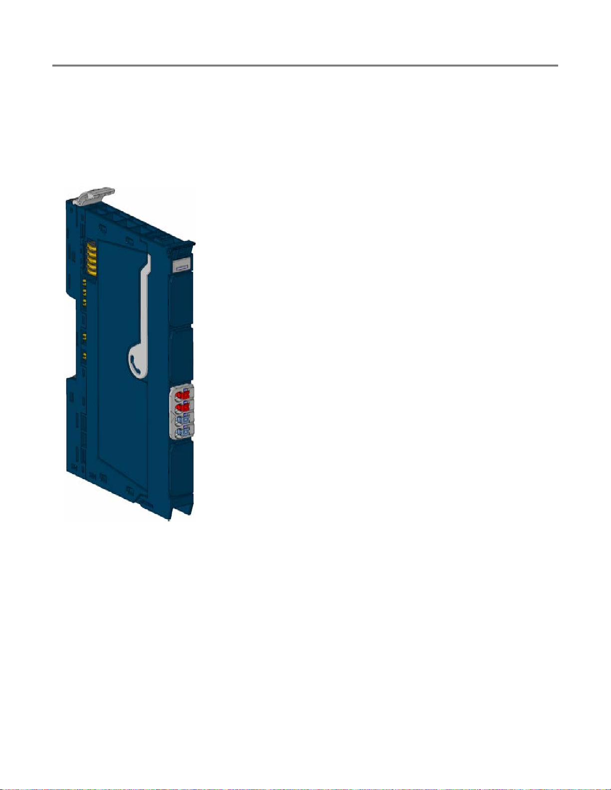
RSTI-EP Slice I/O
GE provides RSTi-EP power-feed modules (EP-7631 and EP-7641), which are used
GFK-2963A Power-feed Modules EP-7631 and EP-7641
December 2015 Potential Distribution Modules EP-700F, EP-710F,
to refresh the current paths and isolate the power supply. The RSTi-EP station‘s
main power supply is always fed in through the network adapter.
has a Module Status LED and connector block LEDs for inspection.
The power-feed module EP7631 must be connected if the current demand of the
series of input modules is too large. The power-feed module EP-7641 must be
connected if the current demand of the series of output modules is too large.
The potential distribution module EP-700F provides 16 connections for the
functional earth.
The potential distribution module EP-711F provides 16 connections for +24 V
from the input current path.
The potential distribution module EP-751F provides 16 connections for +24 V
from the output current path.
The potential distribution module EP-710F provides 16 connections for ground
from the input current path.
Power-feed Module
The potential distribution module EP-750F provides 16 connections for ground
from the output current path.
Power-feed and potential distribution modules are passive modules without
fieldbus communication, therefore they are not considered during configuration.
A maximum of three passive modules (power-feed module, potential distribution
module, empty slot module) may be installed in succession, however the next
module to be installed must be an active module.
The RSTi-EP station is usually installed on a horizontally positioned DIN rail.
Installation on vertically positioned DIN rails is also possible.
Modules should to be allowed to de-energize for a minimum 10 seconds after
power down, prior to starting any maintenance activity.
In the case of a maximum power supply of >8 A and a maximum temperature of
> +55 °C, all four contacts must be connected with 1.5 mm² wiring
Refer to the RSTi-EP Slice I/O User Manual (GFK-2958) for additional information.
Refer to the RSTi-EP Power Supply Reference Guide, a software utility available on
PME V9.00, for detailed power-feed requirements.
Module Features
Spring style technology for ease of wiring
DIN rail mounted
Double-click installation for positive indication of correct installation
EP-711F, EP-751F, and EP-750F
Each module
© 2015 General Electric Company. All Rights Reserved.
*
Indicates a trademark of General Electric Company and/or its subsidiaries. All other trademarks are the property of their respective
owners.
Page 2
2 RSTi-EP Slice I/O Power-feed and
Module
Description
EP-7631
EP-7641
Supply
Supply voltage
20.4V – 28.8V
Maximum feed current for input
modules
Current consumption from output
input path IIN
Maximum feed current for output
modules
Current consumption from output
input path I
OUT
Operating temperature
-20°C to +60°C (-4 °F to +140 °F)
Storage temperature
-40°C to +85°C (-40 °F to +185 °F)
Air humidity (operation/transport)
5% to 95%, noncondensing as per IEC 61131-2
General Data
Width
11.5 mm (0.45 in)
Depth
76 mm (2.99 in)
Height
120 mm (4.72 in)
Weight
76 g (6.21 oz)
76 g (6.21 oz)
EP-700F
EP-711F
EP-751F
EP-710F
EP-750F
Supply
0 V (from input
0 V (from input
General Data
Weight
84 g (2.96 oz)
84 g (2.96 oz)
84 g (2.96 oz)
84 g (2.96 oz)
84 g (2.96 oz)
Power Distribution Modules
GFK-2963A
Ordering Information
EP-7631 Power Module, 1 Channel 24VDC Input Flow 10A
EP-7641 Power Module, 1 Channel 24VDC Output Flow 10A
EP-711F Power Module, 16 Channels 24VDC Potential Distribution +24 VDC from Input Current Path
EP-751F Power Module, 16 Channels 24VDC Potential Distribution +24 VDC from Output Current Path
EP-700F Power Module, 16 Channels 24VDC Potential Distribution Functional Earth
EP-710F Power Module, 16 Channels 24VDC Potential Distribution +0VDC from Input Current Path
EP-750F Power Module, 16 Channels 24VDC Potential Distribution +0VDC from Output Current Path
Specifications
Power-feed Modules
Supply voltage
10 A --
10 mA --
-- 10 A
-- 10 mA
Power Distribution Modules
None 20.4V – 28.8V 20.4V – 28.8V
current path)
current path)
Page 3
RSTi-EP Slice I/O Power-feed and 3
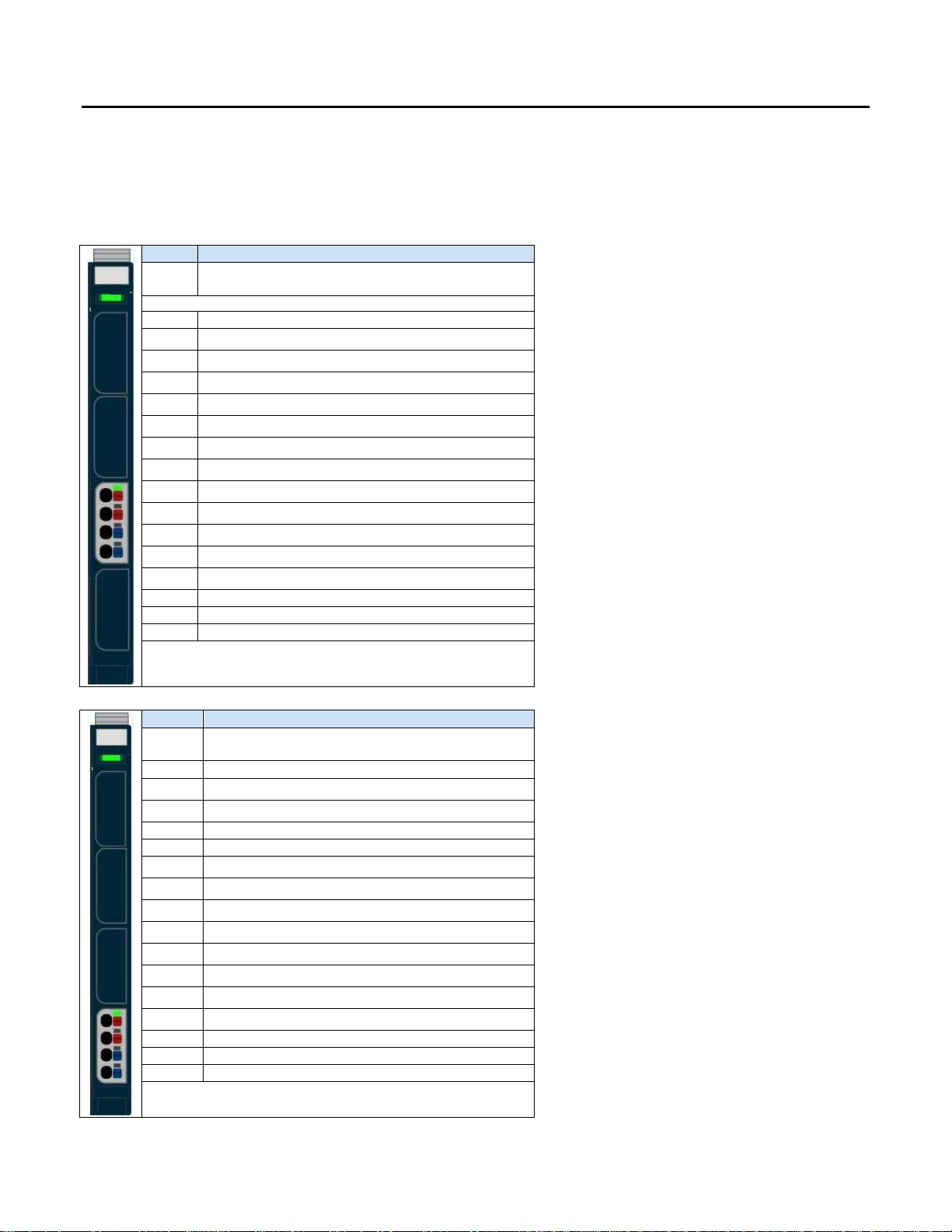
LED
EP-7631
Module
Status
1.1
Green: Supply voltage for input current path > 18 V DC
Red: Supply voltage for input current path < 18 V DC
Red: Internal fuse defective, replace module
4.2
4.3
4.4
LED
EP-7641
Module
Status
1.1
1.4 2.1
3.3
3.4 4.1
Green: Supply voltage for output circuit > 18 V DC
4.2
Red: Supply voltage for output circuit < 18 V DC
4.3 4.4
Red: Internal fuse defective, replace module
Power Distribution Modules
GFK-2963A
LEDs
Potential distribution modules have only a Module Status LED.
Power feed Modules
Green: Voltage applied and is > 18 V DC
1.2
1.3
1.4
2.1
2.2
2.3
2.4
3.1
3.2
3.3
3.4
4.1
Green: Voltage applied and is > 18 V DC
1.2
1.3
2.2
2.3
2.4
3.1
3.2
For public disclosure
Page 4

4 RSTi-EP Slice I/O Power-feed and
24 V DC
GND
24 V DC
Functional
Earth (FE)
Ground
Caution
Power Distribution Modules
GFK-2963A
Field Wiring
The connection frame has one connector block, and two 24 V DC wires can be connected to each connector, along with
two ground connections. Those four connectors are used as shown in the following figure. The Spring style technology
allows either finely stranded or solid wire with crimped wire-end ferrules or ultrasonically welded wires, each with a
maximum cross-section of 1.5 mm² (16 guage), to be inserted easily through the opening in the clamping terminal
without having to use tools. To insert fine stranded wires without wire-end ferrules, the pusher must be pressed in with
a screwdriver and released to latch the wire.
Connector Blocks
Connector Specifications:
• conductor cross-section 0.14 to 1.5 mm² (26 – 16 guage)
• max. ampacity: 10 A
• 4-pole
In the case of a maximum power supply of >8 A and a maximum temperature of > +55 °C, all four
contacts must be connected with 1.5 mm² wiring.
The modules do not have a fused sensor/activator power supply. All cables to the connected sensors/actuators must be
fused corresponding to their conductor cross-sections (as per Standard DIN EN 60204-1, section 12).
Refer to the RSTi-EP Slice I/O User Manual (GFK-2958) for additional information.
For technical assistance, go to http://support.ge-ip.com
.
Page 5

RSTi-EP Slice I/O Power-feed and 5
Power Distribution Modules
GFK-2963A
Connection Diagrams
EP-700F EP-7641 EP-7631
EP-711F EP-751F EP-710F EP-750F
For public disclosure
Page 6

6 RSTi-EP Slice I/O Power-feed and
EP
-
7631
EP
-7641
Power Distribution Modules
GFK-2963A
Connection Block Diagrams
EP-7631
EP-7641
Page 7

RSTi-EP Slice I/O Power-feed and 7
EP-700F
EP-711F
Power Distribution Modules
GFK-2963A
EP-700F
EP-711F
For public disclosure
Page 8

8 RSTi-EP Slice I/O Power-feed and
EP-751F
EP-
710F
EP-750F
Power Distribution Modules
GFK-2963A
EP-751F
EP710F
EP-750F
Page 9

RSTi-EP Slice I/O Power-feed and 9
1-800-433-2682
Power Distribution Modules
GFK-2963A
Installation in Haza r dous Areas
EQUIPMENT LABELED WITH REFERENCE TO CLASS I, GROUPS A, B, C & D, DIV. 2 HAZARDOUS AREAS IS SUITABLE FOR USE IN
CLASS I, DIVISION 2, GROUPS A, B, C, D OR NON-HAZARDOUS AREAS ONLY
WARNING - EXPLOSION HAZARD - SUBSTITUTION OF COMPONENTS MAY IMPAIR SUITABILITY FOR CLASS I, DIVISION 2;
WARNING - EXPLOSION HAZARD - WHEN IN HAZARDOUS AREAS, TURN OFF POWER BEFORE REPLACING OR WIRING
MODULES; AND
WARNING - EXPLOSION HAZARD - DO NOT CONNECT OR DISCONNECT EQUIPMENT UNLESS POWER HAS BEEN
SWITCHED OFF OR THE AREA IS KNOWN TO BE NONHAZARDOUS.
ATEX Marking
II 3 G Ex nA IIC T4 Gc
Ta: -20°C to +60°C (-4° F to +140 °F)
Release History
Catalog Number
EP-7631, EP-7641, EP-700F, EP-711F,
EP-751F, EP-710F, EP-750F
EP-7631, EP-7641, EP-700F, EP-711F,
EP-751F, EP-710F, EP-750F
Firmware
Version
N/A
N/A
Date Comments
Dec-2015 Documentation update only
Oct-2015 Initial Release
Important Product Information for this Release
Updates
None - Documentation update only
Funcional Compatibility
N/A
Problems Resolved by this Release
None - Documentation update only
New Features and Enhancements
None - Documentation update only
Known Restrictions and Open Issues
None
Operational Notes
None
Product Documentation
RSTi-EP Slice I/O Module User Manual (GFK-2958)
RSTi-EP Slice I/O Functional Safety Module User Manual (GFK-2956)
1-434-978-5100
www.ge-ip.com
For public disclosure
 Loading...