

RSTI-EP Slice I/O
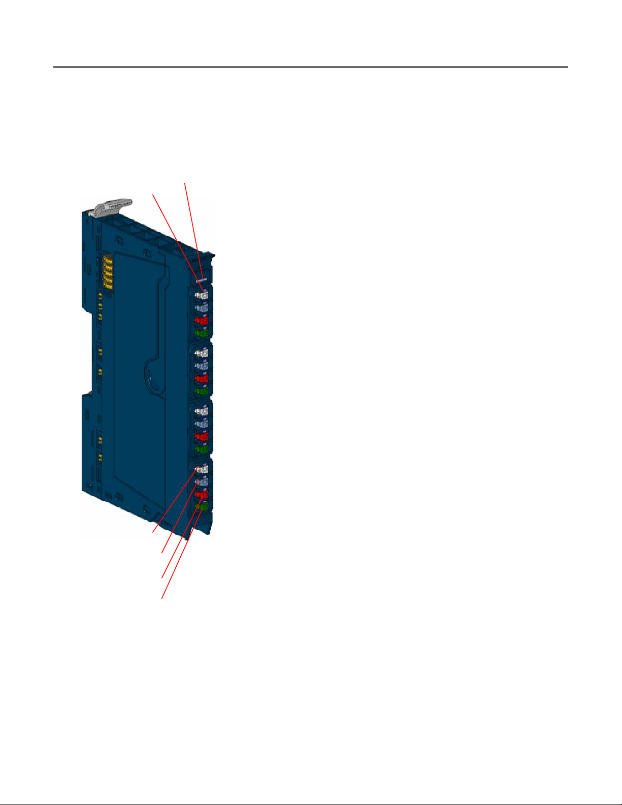
Module Status
LED
Channel Status
LEDs
Digital Input Connector
Ground
24 V DC
FE
GE provides a range of RSTi-EP analog input modules with 4 or 8 inputs and up
Analog Input Modules
GFK-2960A `EP-3164, EP-3264, EP-3124, EP-3368, EP-3468
December 2015 EP-3704, EP-3804
to 16-bit resolution. The measurement range is defined by parameterization
with an accuracy of 0.1% FSR with the exception of EP3124, which 0.25% FSR.
The parameters for the measurement range can be individually set for each
channel.
The EP-3704 module can detect up to 4 analog resistance temperature
detectors. The resolution is 16 bit per channel.
The EP-3804 module can detect up to 4 analog thermocouple sensors or
voltages between ± 15 mV and ± 2 V.
The wiring connectors on each module are color coded for ease of wiring.
Refer to the section,
Each module features a type plate, which includes identification information,
the key technical specifications, and a block diagram. In addition, a QR code
allows for direct online access to the associated documentation. The software
for reading the QR code must support inverted QR codes.
Markers are available as accessories for labelling equipment. Each I/O module
can be labelled using the markers to ensure clear identification when
replacing individual modules or electronic units.
A green Module Status LED indicates there is communication on the system
bus. In addition, each channel has its own status LED.
Field Wiring for additional information.
The RSTi-EP station is usually installed on a horizontally positioned DIN rail.
Installation on vertically positioned DIN rails is also possible.
Modules should to be allowed to de-energize for a minimum 10 seconds after
power down, prior to starting any maintenance activity.
Refer to the RSTi-EP Slice I/O Module User Manual (GFK-2958) for additional
information.
Refer to the RSTi-EP Power Supply Reference Guide, a software utility available
on PME V9.00, for detailed power-feed requirements.
Module Features
Spring style technology for ease of wiring
DIN rail mounted
Double-click installation for positive indication of correct installation
Up to 8 analog inputs
Supports indirect firmware update through network adapter using Web
Analog Input Module
server
Supports hot insertion and extraction
© 2015 General Electric Company. All Rights Reserved.
*
Indicates a trademark of General Electric Company and/or its subsidiaries. All other trademarks are the property of their respective
owners.
2 RSTi-EP Slice I/O Analog Input Modules
EP-3124
EP-3164
EP-3264
EP-3368
EP-3468
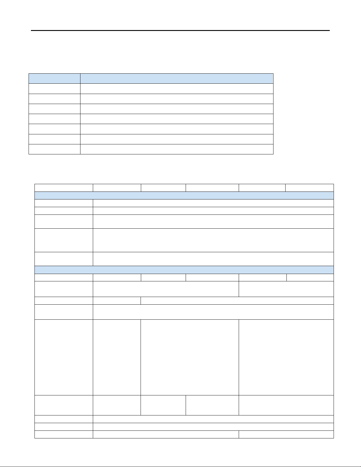
System Data
Data
Process, parameter and diagnostic data depend on the network adapter used.
Interface
RSTi-EP system bus
rate
Overvoltage category: II
Against: 0V - ±50V
Channel-Channel: ±3V
Inputs
Number
4 4 4 8 8
2. Current (0 to 20 mA, 4 to 20 mA)
4 to 20 mA)
Resolution
12 bits
16 bits
Default: disabled
supply current
A
combination
Sensor connection
2-wire, 3-wire, 3-wire + FE
Conversion time
1 ms
Internal resistance
Voltage mode: 100 kΩ; Current mode: 41.2 Ω
approx. 45 Ω
GFK-2960A
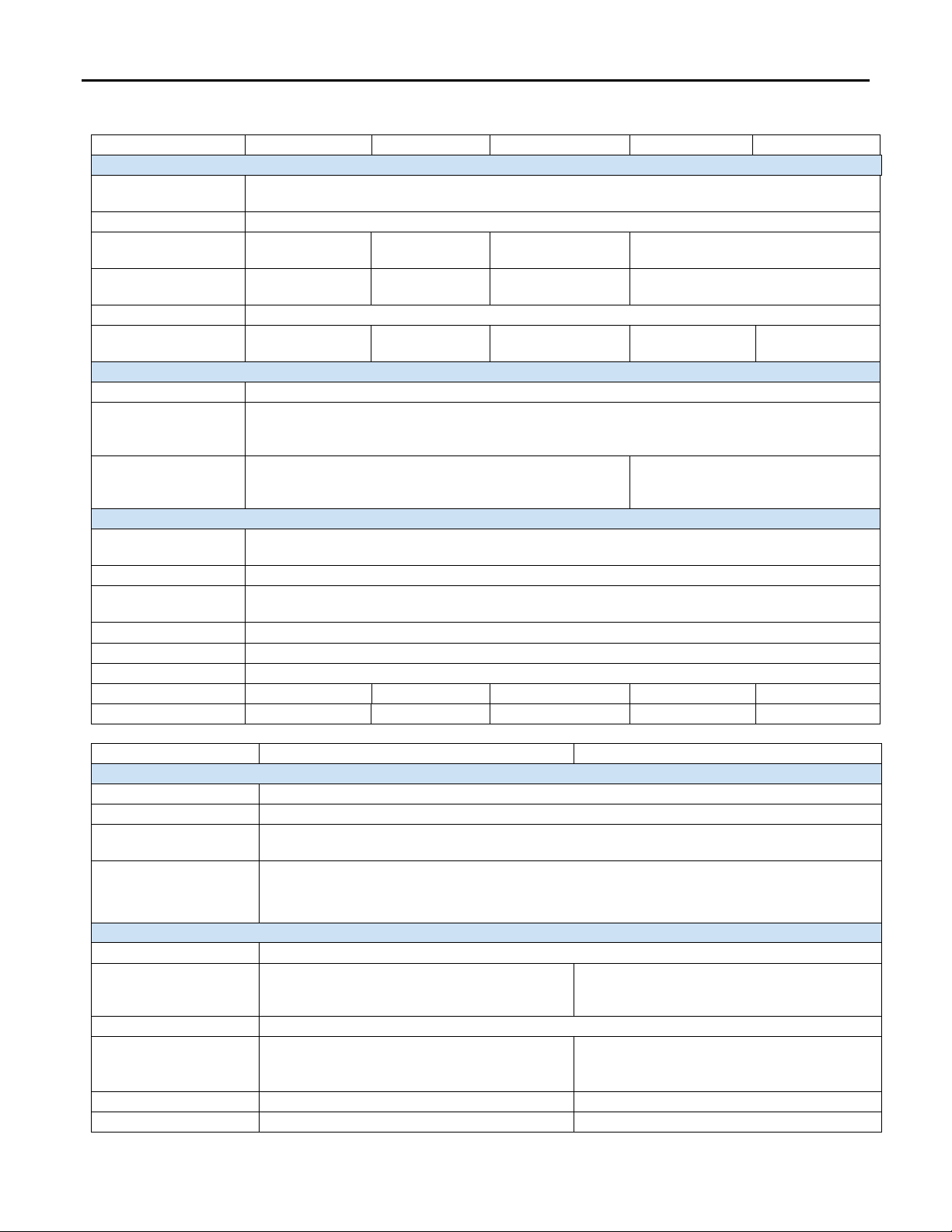
Ordering Information
Module Description
EP-3124 Analog Input, 4 Channels Voltage/Current 12 Bits 2, 3, or 4 Wire
EP-3164 Analog Input, 4 Channels Voltage/Current 16 Bits 2, 3, or 4 Wire
EP-3264 Analog Input, 4 Channels Voltage/Current 16 Bits with Diagnostics 2, 3, or 4 Wire
EP-3368 Analog Input, 8 Channels Current 16 Bits 2, 3, or 4 Wire
EP-3468 Analog Input, 8 Channels Current 16 Bits 2, 3, or 4 Wire, Channel Diagnostic
EP-3704 Analog Input, 4 Channels RTD 16 Bits with Diagnostics 2, 3, or 4 Wire
EP-3804 Analog Input, 4 Channels TC 16 Bits with Diagnostics 2, 3, or 4 Wire
Specifications
System bus transfer
Potential isolation
Common mode
voltage
Input values
Frequency
suppression
Accuracy
48 Mbps
Test voltage: max. 28.8 V within one channel, 500 V DC field/system
Pollution severity level: 2
1. Voltage (0 to 5 V, ±5 V, 0 to 10 V, ±10 V, 1 to 5 V, 2 to 10 V)
Options: disabled (0) / 50 Hz (1) / 60 Hz (2) / Average over 16 values (3)
0.25 % max. at 25
°C (77 °F)
50 ppm/K max.
Temperature
coefficient
max. –10 mV/A
additional
inaccuracy in the
voltage mode due
to sensor power
0.1 % max. at 25 °C (77 °F)
50 ppm/K max. Temperature coefficient
max. –10 mV/A additional inaccuracy in
the voltage mode due to sensor power
supply current
Current input (0 to 20 mA,
0.1 % max. at 25 °C (77 °F)
50 ppm/K max. Temperature
coefficient
Sensor supply
max. 2 A per plug,
total max. 8 A
max. 2 A per
plug, total max. 8
max. 0,5 A per plug
max. 125 mA per channel; channel 0 to
3 and 4 to 7 respectively are fused in
RSTi-EP Slice I/O Analog Input Modules 3
EP-3124
EP-3164
EP-3264
EP-3368
EP-3468
Inputs continued
protection
protective circuit
circuit to +24 V
20°C)
Module diagnostics
Yes
diagnostics
Supply
Supply voltage
20.4V – 28.8V via system bus
path I
SYS
path IIN
General data
temperature
Storage temperature
-40°C to +85°C (-40 °F to +185 °F)
(operation/transport)
11.5 mm (0.45 in)
Depth
76 mm (2.99 in)
Height
120 mm (4.72 in)
Weight
87 g (3.07 oz)
89 g (3.14 oz)
89 g (3.14 oz)
90 g (3.17 oz)
90 g (3.17 oz)
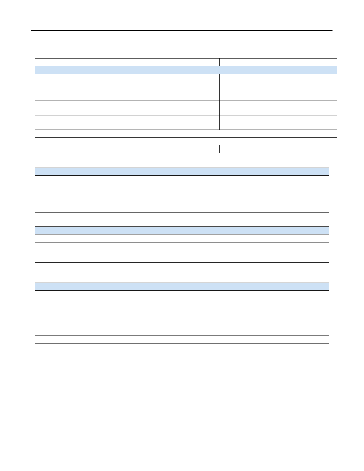
EP-3704
EP-3804†
System Data
Data
Process, parameter and diagnostic data depend on the network adapter used.
Interface
RSTi-EP system bus
rate
Overvoltage category: II
Inputs
Number
4
150 Ω, 300 Ω, 500 Ω, 1 kΩ, 2 kΩ, 4 kΩ
Resolution
16 bits
junction measurement error)
Temperature coefficient
±50 ppm/K max.
50 ppm
Sensor connection
2-wire, 3-wire, 4-wire
2-wire
GFK-2960A
Reverse polarity
Short-circuit-proof
Response time of the
Reset time
Individual channel
Current consumption
from system current
Current consumption
from input current
Operating
Air humidity
Width
< 0.1 s with short-
-- -- --
No
25 mA + sensor supply current 20 mA + load
Yes
Yes
< 50 ms < 50 ms < 0.1 s with short-circuit to +24 V
Temperature-dependent (< 30 s at
No Yes No Yes
8 mA
-20°C to +60°C (-4 °F to +140 °F)
5% to 95%, noncondensing as per IEC 61131-2
System bus transfer
Potential isolation
Sensor types
Accuracy
48 Mbps
Test voltage: max. 28.8 V within one channel, 500 V DC field/system
Pollution severity level: 2
Pt100, Pt200, Pt500, Pt1000, Ni100, Ni120, Ni 200,
Ni500, Ni1000, Cu10, and resistors with 40 Ω, 80 Ω,
max. 0.2 % FSR / 0.3 % FSR for Ni sensors /
0.6 % FSR for Cu10
For public disclosure
J, K, T, B, N, E, R, S, L, U, C, mV
Conversion time ≥ 80 ms: 10 μV + 0.1 % of
voltage measurement range (without cold-
4 RSTi-EP Slice I/O Analog Input Modules
EP-3704
EP-3804†
Inputs continued
Ni1000, 500 Ω, 1 kΩ, 2 kΩ, 4 kΩ)
int. accuracy ≤ 3 K
measurement range
Ω in all other measuring ranges
Temperature range
-200 to +850°C (-328 to 1562 °F)
Conversion time
36 to 240 ms, adjustable
Internal resistance
--
> 1 MΩ
EP-3704
EP-3804†
Inputs (Continued)
Channel to channel: max. ±2 V
--
Channel to voltage supply: max. ±50 V
protection
Module diagnostics
Yes
diagnostics
Supply
Supply voltage
20.4V – 28.8V via system bus
path I
IIN
General data
Operating temperature
-20°C to +60°C (-4 °F to +140 °F)
Storage temperature
-40°C to +85°C (-40 °F to +185 °F)
(operation/transport)
11.5 mm (0.45 in)
Depth
76 mm (2.99 in)
Height
120 mm (4.72 in)
Weight
91 g (3.21 oz)
86 g (3.03 oz)
Warm up time for the module to get the required accuracy is 30 minutes
GFK-2960A
Depending on the sensor type 0,75 mA (Pt100,
Sensor current
Ni100, Ni120, Cu10, 40 Ω, 80 Ω, 150 Ω, 300 Ω) or
0,25 mA (Pt200, Pt500, Pt1000, Ni200, Ni500,
0,25 mA for the cold-junction compensation with
a Pt1000
Cold junction
compensation
Max. wire resistance /
Common mode input
voltage range
Reverse polarity
Individual channel
Current consumption
from system current
SYS
Current consumption
from input current path
--
2.5 Ω / 40 Ω, 5 Ω / 80 Ω, 10 Ω / 150 Ω and Cu10, 25
Yes
Yes
8 mA
20 mA
Internal and external (Pt1000),
--
Air humidity
Width
†
5% to 95%, noncondensing as per IEC 61131-2

RSTi-EP Slice I/O Analog Input Modules 5
Product
I
IIN
I
IS
IL
EP-3124
8 mA
25 mA
-- x --
EP-3164
8 mA
25 mA
-- x --
EP-3264
8 mA
25 mA
-- x --
EP-3368
8 mA
20 mA
--
--
--
EP-3468
8 mA
20 mA
--
--
--
EP-3704
8 mA
20 mA
--
--
--
EP-3804
8 mA
20 mA
--
--
--
I
x
Current consumption from the system current path
Must be included when calculating the power supply
LED
EP-3124
EP-3164
EP-3224
EP-3704
EP-3804
1.1
Red: channel error
Red: channel error
Red: channel error
Red: channel error
Red: channel error
1.2
--
--
--
--
(with current < 1 mA)
1.4
--
--
--
--
2.1
Red: channel error
Red: channel error
Red: channel error
Red: channel error
Red: channel error
2.2
--
--
--
--
(with current < 1 mA)
2.4
--
--
--
--
--
3.1
Red: channel error
Red: channel error
Red: channel error
Red: channel error
Red: channel error
3.2
--
--
--
--
--
(with current < 1 mA)
3.4
--
--
--
--
--
4.1
Red: channel error
Red: channel error
Red: channel error
Red: channel error
Red: channel error
4.2
--
--
--
--
--
(with current < 1 mA)
4.4
--
--
--
--
GFK-2960A
Current Demand for Analog Input Modules
SYS
SYS
I
Power consumption from input current path
IN
Power consumption from output current path
I
OUT
Current demand of the connected sensors
I
S
Current demand of the connected actuators
I
L
OUT
LEDs
Module
Status
1.3
2.3
3.3
Green:
Communication over
the system bus
Red: Module System
Fault or Diagnostic
Fault
-- --
-- --
-- --
Green:
Communication over
the system bus
Red: Module System
Fault or Diagnostic
Fault
Green:
Communication over
the system bus
Red: Module System
Fault or Diagnostic
Fault
Red: +24 V short
circuit or line break
Red: +24 V short
circuit or line break
Red: +24 V short
circuit or line break
Green:
Communication over
the system bus
Red: Module System
Fault or Diagnostic
Fault
--
-- --
--
--
-- --
-- --
Green:
Communication over
the system bus
Red: Module System
Fault or Diagnostic
Fault
4.3
-- --
Red: +24 V short
circuit or line break
For public disclosure
-- --
--

6 RSTi-EP Slice I/O Analog Input Modules
LED
EP-3368
EP-3468
1.1
Red: channel error
Red: channel error
2.1
Red: channel error
Red: channel error
3.1
Red: channel error
Red: channel error
4.1
Red: channel error
Red: channel error
5.1
Red: channel error
Red: channel error
6.1
Red: channel error
Red: channel error
7.1
Red: channel error
Red: channel error
8.1
Red: channel error
Red: channel error
GFK-2960A
Module
Status
Green: Communication over the system bus
Red: Module System Fault or Diagnostic Fault
Green: Communication over the system bus
Red: Module System Fault or Diagnostic Fault
Field Wiring
The connection frame can take up to four connectors, and four wires can be connected to each connector. The Spring
style technology allows for either finely stranded or solid wire with crimped wire-end ferrules or ultrasonically welded
wires, each with a maximum cross-section of 1.5 mm² (16 guage), to be inserted easily through the opening in the
clamping terminal without having to use tools. To insert fine stranded wires without wire-end ferrules, the pusher must
be pressed in with a screwdriver and released to latch the wire.
Note: The four wire connector image is for illustration of color coding only.
Connector Specifications:
The pushers are color-coded for the following connections:
Refer to the RSTi-EP Slice I/O Module User Manual (GFK-2958) for additional information.
For technical assistance, go to http://support.ge-ip.com
Connector with Four Wire Connectors Connector for HD Module (requires special tool)
• conductor cross-section 0.14 to 1.5 mm² (26 – 16 guage)
• max. ampacity: 10 A
• 4-pole
• White Signal
• Blue GND
• Red 24 V DC
• Green Functional earth (FE)
.

RSTi-EP Slice I/O Analog Input Modules 7
GFK-2960A
Connection Diagrams
EP-3164 and EP-3264 EP-3124
EP-3368 and EP-3468
For public disclosure

8 RSTi-EP Slice I/O Analog Input Modules
EP-3164
GFK-2960A
EP-3704 EP-3804
Note: For EP-3804, the external CJC shown with a dotted line is optional. An internal CJC can also be used.
Connection Block Diagrams
EP-3164

RSTi-EP Slice I/O Analog Input Modules 9
EP-3264
EP-3124
EP-3368
GFK-2960A
EP-3264
EP-3124
EP-3368
For public disclosure

10 RSTi-EP Slice I/O Analog Input Modules
EP-3468
EP
-
3704
EP-3804
GFK-2960A
EP-3468
EP-3704
EP=3804

RSTi-EP Slice I/O Analog Input Modules 11
1-800-433-2682
EP-3124, EP-3164, EP-3264,
GFK-2960A
Installation in Haza r dous Areas
EQUIPMENT LABELED WITH REFERENCE TO CLASS I, GROUPS A, B, C & D, DIV. 2 HAZARDOUS AREAS IS SUITABLE FOR USE IN
CLASS I, DIVISION 2, GROUPS A, B, C, D OR NON-HAZARDOUS AREAS ONLY
WARNING - EXPLOSION HAZARD - SUBSTITUTION OF COMPONENTS MAY IMPAIR SUITABILITY FOR CLASS I, DIVISION 2;
WARNING - EXPLOSION HAZARD - WHEN IN HAZARDOUS AREAS, TURN OFF POWER BEFORE REPLACING OR WIRING
MODULES; AND
WARNING - EXPLOSION HAZARD - DO NOT CONNECT OR DISCONNECT EQUIPMENT UNLESS POWER HAS BEEN
SWITCHED OFF OR THE AREA IS KNOWN TO BE NONHAZARDOUS.
ATEX Marking
II 3 G Ex nA IIC T4 Gc
Ta: -20°C to +60°C (-4° F to +140 °F)
Release History
Catalog Number
EP-3124, EP-3164, EP-3264,
EP-3704, EP-3804
EP-3704, EP-3804
Firmware
Version
01.00 Dec-2-15 Documentation update only
01.00 Nov-2015 Initial Release
Date Comments
Important Product Information for this Release
Updates
None - Documentation update only
Funcional Compatibility
N/A
Problems Resolved by this Release
None – Initial Release
New Features and Enhancements
None - Documentation update only
Known Restrictions and Open Issues
None
Operational Notes
None
Product Documentation
RSTi-EP Slice I/O Module User Manual (GFK-2958)
RSTi-EP Slice I/O Functional Safety Module User Manual (GFK-2956)
1-434-978-5100
www.ge-ip.com
For public disclosure
 Loading...