

Page 1

RSTI-EP Slice I/O
Module Status
LED
Safety Circuit 1
LED
Connector
Blank
Connector
Block
Manual Start
Circuit
Connectors
Autostart
Circuit
Connectors
NC
(Not Connected)
OSSD
24 V DC
Ground
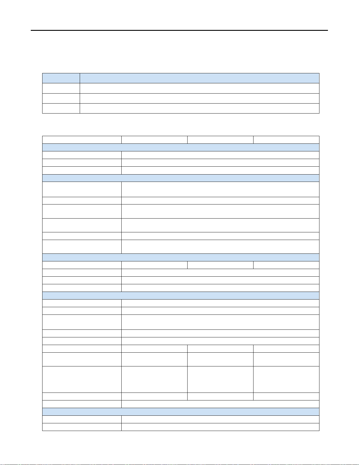
GE provides 3 varients of RSTi-EP safe feed modules EP 1901: one safe input,
GFK-2968A Safe Feed-input Modules
December 2015 EP-1901, EP-1902, EP-1922
EP 1902: two safe inputs and EP 1922: two safe inputs, with delayed
disconnection, which are intended for connecting safety-related equipment.
The RSTi-EP safe feed-input modules are controlled using contact-based
safety transducers and/or safety transducers with OSSD (Output Signal
Switching Device) inputs. The safety function consists of the safe
EP-1901 Module
disconnection of 24 V outputs, the safe state of which is 24 V switched off
(current path for outputs and the OSSD output is switched off).
All input sensors are independently supplied via separate voltage paths and
report the current machine status to the control unit.
Each RSTi-EP safe feed-input module safely switches off all following
modules that are supplied by the output current path (until the next EP-7641
power module) and thus creates a safety segment. To switch the 24 V OSSD
voltage back on, either an automatic or a manual start can be selected.
• Automatic start: the safe output current path is switched on
immediately after resetting the safety circuit(s).
• Manual start: the output current path is only switched on again if the
start button has been held down for a preset length of time.
With the delay module (EP-1922), switching off can be delayed by a defined
time so that, for example, a machine can be shut down in a controlled
manner. The delay time can be set in four steps between 0 and 60 seconds
(corresponds to stop category 1 as per EN 60204.
The wiring connectors on each module are color coded for ease of wiring.
Refer to the section, Field Wiring for additional information.
The RSTi-EP station is usually installed on a horizontally positioned DIN rail.
Installation on vertically positioned DIN rails is also possible.
Modules should to be allowed to de-energize for a minimum 10 seconds
after power down, prior to starting any maintenance activity.
Refer to the RSTi-EP Slice I/O Functional Safety Module User Manual (GFK-
2956) for additional information.
Refer to the RSTi-EP Power Supply Reference Guide, a software utility
available on PME V9.00, for detailed power-feed requirements.
Module Features
SIL 3 compliant (IEC 62061 and EN ISO 13849-1, category 4, PL e)
OSSD outputs
Emergency-stop circuits
Wire breakage and short-circuit detection
Optional delayed shutdown available
Spring style technology for ease of wiring
DIN rail mounted
Double-click installation for positive indication of correct installation
EP-1922 provides optional shutdown time delay in four steps from 0 to
60 seconds
Supports indirect Firmware update through network adapter using web
server.
© 2015 General Electric Company. All Rights Reserved.
*
Indicates a trademark of General Electric Company and/or its subsidiaries. All other trademarks are the property of their respective
owners.
Page 2
2 RSTi-EP Slice I/O Safe Feed-input Modules
EP-1901
EP-1902
EP-1922
System Data
Data
Process and diagnostic data depend on the network adapter used.
Interface
RSTi-EP system bus
System bus transfer rate
48 Mbps
Safety-related data
regarding the entire safety chain
DC (Diagnostic Coverage)
96.64%
dangerous)
Hour)
SSF (Safe Failure Fraction)
98.58 %
Tolerance)
Inputs
Safety inputs
1 x 2channel
2 x 2channel
2 x 2channel
Input type
Type 3 as per IEC 61131-2
Inputs for start function
2 (manual start and autostart)
Input type
Type 3 as per IEC 61131-2
Outputs
Safety output (OSSD)
1
Output current
8 A (not for capacitive load)
(see below)
Turn-off time
< 20 ms
Turn-on time
< 2 s
Output SS1
--
--
1
as per IEC 61131-2
fuse (see below)
Auxiliary outputs
2 x 2
3 x 2
3 x 2
Output current
max. 10 A (only to support the inputs dedicated inputs)
Diagnosis
Module diagnosis
Yes
Individual channel diagnosis
Yes
GFK-2968A
Ordering Information
Module Description
EP-1901 1 Safe Feed-Input, 24 VDC
EP-1902 2 Safe Feed-Inputs, 24 VDC
EP-1922 2 Safe Feed-Inputs, 24 VDC, Programmable Delay
Specifications
Achievable safety level
MTTFd (Mean Time To Failure
PFH (Probability of Failure per
HFT (Hardware Fault
Overload protection
SIL3 (IEC 61508), SIL CL3 (IEC 62061), PLe and Cat. 4 (DIN EN ISO 13849-1),
> 100 years
6.27 x 10⁻⁹ 1/h
1
Excess temperature proof and overload-proof, short circuit proof with external fuse
Output current
Overload protection
--
--
--
--
0,5 A, overload behaviour
Over-temperature,
Overload and Short Circuit
protection with external
Page 3
RSTi-EP Slice I/O Safe Feed-input Modules 3
EP-1901
EP-1902
EP-1922
Supply
Supply voltage
20.4V – 28.8V via system bus
External pre-fusing
mandatory: super fast, max. 8 A
Reverse battery protection
Yes
network adapter), typ.
respective power segment)
EP-1901
EP-1902
EP-1922
General data
Operating temperature
-20°C to +60°C (-4 °F to +140 °F)
Storage temperature
-40°C to +85°C (-40 °F to +185 °F)
(operation/transport)
(0.45 in)
Depth
Height
120 mm (4.72 in)
Weight
80 g (2.82 oz)
82 g (2.89 oz)
84 g (2.96 oz)
Product
I
IIN
I
IS
IL
EP-1901
8 mA
45 mA
--
--
x
EP-1902
8 mA
45 mA
--
--
x
EP-1922
8 mA
45mA
--
-
x
I
x
Current consumption from the system current path
Must be included when calculating the power supply
GFK-2968A
Current consumption (IIN in the
power segment of the fieldbus
8 mA
Current consumption (IIN in the
Air humidity
Width
SYS
I
Power consumption from input current path
IN
Power consumption from output current path
I
OUT
Current demand of the connected sensors
I
S
Current demand of the connected actuators
I
L
5% to 95%, noncondensing as per IEC 61131-2
Current Demand for Safe feed-Input Modules
SYS
OUT
45 mA
11.5 mm
76 mm (2.99 in)
For public disclosure
Page 4

4 RSTi-EP Slice I/O Safe Feed-input Modules
LED
EP-1901
EP-1902
EP-1922
1.1
Yellow: Safety circuit 1 OK
Yellow: Safety circuit 1 OK
Yellow: Safety circuit 1 OK
1.2
--
1.3
--
1.4
--
--
2.2
--
--
--
2.3
--
--
--
2.4
--
--
--
3.1
--
--
--
3.2
--
--
--
3.3
--
--
--
3.4
--
--
--
4.1
--
--
Yellow: SS1 output active
4.2
Yellow: 24 V DC_OSSD active
Yellow: 24 V DC_OSSD active
Yellow: 24 V DC_OSSD active
valid range
valid range
valid range
GFK-2968A
LEDs
Module
Status
2.1
4.3
4.4
Green: Feed-in voltage in
-- -- --
Green: Communication over the system bus
--
--
--
Yellow: Safety circuit 2 OK Yellow: Safety circuit 2 OK
Green: Feed-in voltage in
Green: Feed-in voltage in
Page 5

RSTi-EP Slice I/O Safe Feed-input Modules 5
Safety
, Start,
and Autostart
Connector
Blank
Connector
Power
Connector
GFK-2968A
Field Wiring
The connection frame can take up to four connectors, and four wires can be connected to each connector. Those four
connectors will be comprised of a Power Connector, one or more Safety, Start, and Autostart Connector(s), and Blank
Connectors as needed to fill in the connection frame. The Spring style technology allows either finely stranded or solid
wire conductors with crimped wire-end ferrules or ultrasonically welded wires, each with a maximum cross-section of
1.5 mm² (16 guage), to be inserted easily through the opening in the clamping terminal without having to use tools. To
insert fine stranded wires without wire-end ferrules, the pusher must be pressed in with a screwdriver and released to
latch the wire.
Connector Specifications:
• conductor cross-section 0.14 to 1.5 mm² (26 – 16 guage)
• max. ampacity: 10 A
• 4-pole
The pushers are color-coded for the following connections:
• White Signal
• Blue GND
• Red 24 V DC
The modules do not have a fused sensor/activator power supply. All cables to the connected sensors/actuators must be
fused corresponding to their conductor cross-sections (as per Standard DIN EN 60204-1, section 12).
Refer to the RSTi-EP Slice I/O Functional Safety Module User Manual (GFK-2956) for additional information.
For technical assistance, go to http://support.ge-ip.com
.
For public disclosure
Page 6

6 RSTi-EP Slice I/O Safe Feed-input Modules
To ensure the safety functions regard the following instructions for
Input
Delay
Function
1 2 3
4
= ON
= OFF
X = Setting not relevant
GFK-2968A
Dip Switches
adjustment:
–
DIP switches of equal numbers must have identical positions in
both rows.
–
If an external device generating pulses is connected to a safety
input of the EP-1922, this input must be operated in mode no test
pulses (DIP switch
–
When operating in mode no test pulses
–
the test pulses of the external device must be shorter than 2
ms, otherwise the safe output will be deactivated
–
a safe laying of cables can be neccessary depending on the
required safety level
Note: Use a ball point pen or something similar to set the DIP
DIP Switch on EP1922 Module
switches and avoid spiky or sharp-edged tools.
setting ON).
Safety input 0 evaluating own test pulses
Safety input 0 no test pulses
Safety input 1 evaluating own test pulses
Safety input 1 no test pulses
24 V Safe: no delay
24 V Safe: delay 1 second
24 V Safe: delay 30 seconds
24 V Safe: delay 60 seconds
x
x
x x
x x
x x
x x
x x x
x x x
x x
x x
Setting options for the DIP
Page 7

RSTi-EP Slice I/O Safe Feed-input Modules 7
GFK-2968A
Connection Diagrams
EP-1901 EP-1902
EP-1922
For public disclosure
Page 8

8 RSTi-EP Slice I/O Safe Feed-input Modules
EP-1901
EP
-1902
EP-1922
GFK-2968A
Connection Block Diagrams
EP-1901
EP-1902
EP-1922
Page 9

RSTi-EP Slice I/O Safe Feed-input Modules 9
1-800-433-2682
GFK-2968A
Installation in Haza r dous Areas
EQUIPMENT LABELED WITH REFERENCE TO CLASS I, GROUPS A, B, C & D, DIV. 2 HAZARDOUS AREAS IS SUITABLE FOR USE IN
CLASS I, DIVISION 2, GROUPS A, B, C, D OR NON-HAZARDOUS AREAS ONLY
WARNING - EXPLOSION HAZARD - SUBSTITUTION OF COMPONENTS MAY IMPAIR SUITABILITY FOR CLASS I, DIVISION 2;
WARNING - EXPLOSION HAZARD - WHEN IN HAZARDOUS AREAS, TURN OFF POWER BEFORE REPLACING OR WIRING
MODULES; AND
WARNING - EXPLOSION HAZARD - DO NOT CONNECT OR DISCONNECT EQUIPMENT UNLESS POWER HAS BEEN
SWITCHED OFF OR THE AREA IS KNOWN TO BE NONHAZARDOUS.
ATEX Marking
II 3 G Ex nA IIC T4 Gc
Ta: -20°C to +60°C (-4° F to +140 °F)
Release History
Catalog Number
EP-1901, EP-1902, EP-1922 01.13
EP-1901, EP-1902, EP-1922 01.13 Nov-2015 Initial Release
Firmware
Version
Date Comments
Dec-2015 Documentation update only
Important Product Information for this Release
Updates
None – Documentation update only
Funcional Compatibility
N/A
Problems Resolved by this Release
None – Documentation update only
New Features and Enhancements
None – Documentation update only
Known Restrictions and Open Issues
None
Operational Notes
None
Product Documentation
RSTi-EP Slice I/O Module User Manual (GFK-2958)
RSTi-EP Slice I/O Functional Safety Module User Manual (GFK-2956)
1-434-978-5100
www.ge-ip.com
For public disclosure
 Loading...