

Page 1
Safety and Distributed Control
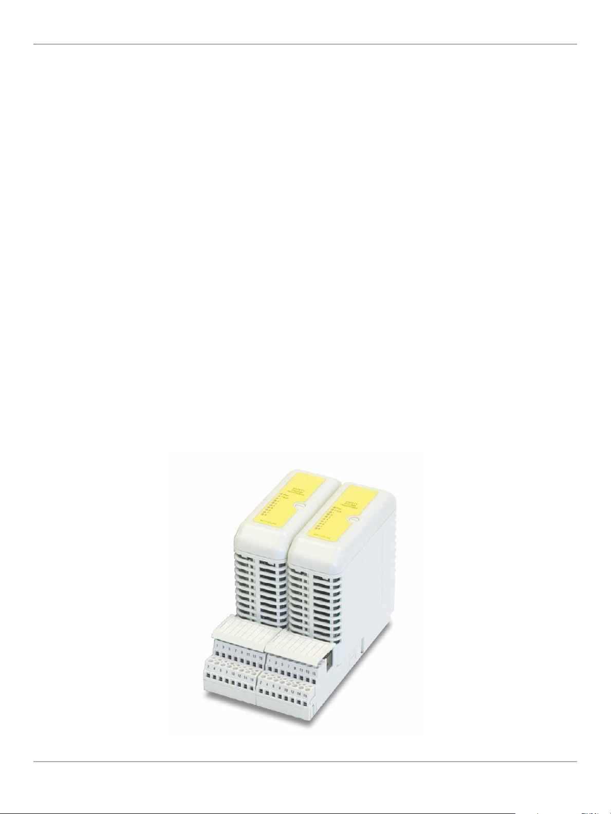
PAC8000 SafetyNet
SafetyNet IO Modules
SafetyNet IO Modules interface to safety system field wiring via Field Terminals. The IO Modules and the Field Terminals mount on
Carriers that provide mechanical support, but also connect the internal communication bus and power supply connections to the
Modules. The IO Modules are certified as suitable for use in SIL 2 safety-related applications.
• Certification
The SafetyNet IO Modules are
certified for use in safety-related
applications up to and including SIL 2.
The SafetyNet System achieves this
certification with a 1oo1D architecture.
The SafetyNet IO Modules have been
designed specifically for safety-related
applications and are certified on the
basis of the excellence of their design.
The certification does not depend on
“proven in use” data.
• Diagnostics
The IO Modules perform
comprehensive internal diagnostic tests
as an essential part of ensuring that
the IO can carry out the required safety
function. If the SafetyNet IO Module’s
internal diagnostics detect a fault that
would prevent the SafetyNet System
from carrying out its safety function,
then it will initiate a controlled
shutdown. A controlled shutdown has
two objectives – firstly, to ensure that
the IO Module enters its failsafe mode;
and secondly, to record sufficient data
to allow the reason for the shutdown to
be determined. If a SafetyNet Module
enters a controlled shutdown, then
all IO channels are deactivated: input
channels are not scanned; and output
channels are de-energized.
• Bussed Field Power
The Bussed Field Power (BFP)
connectors on the rear of IO Module
Carriers provide the power connections
for field instruments wired to the IO
Modules. For the SafetyNet System,
BFP must be 24 VDC and supplied by
MTL’s 8914-PS-AC units. These power
supplies may be used in redundant
pairs, if required.
• Live Maintenance
SafetyNet IO Modules can be removed
and replaced in a Class 1, Division 2
or Zone 2 hazardous area - once the
relevant Bussed Field Power (BFP)
connection has been isolated using
an appropriate hazardous area switch
(such as the MTL951). Removing
and replacing the Modules does
not interrupt the operation of the
other parts of the node. If a Module
is replaced by another Module of
identically the same type, then no
intervention is required for the System
to begin operating normally once the
Bussed Field Power is restored.
• Line Fault Monitoring
In addition to the comprehensive
internal diagnostics the SafetyNet IO
Modules can monitor field wiring for
line faults.
continued next page
www.geautomation.com
Automation & Control Systems
5.31
Page 2

Safety and Distributed Control
• Event Logging
Data from SafetyNet IO Modules can
be time stamped and stored by the
SafetyNet Controller before being
downloaded to the PAC8000 SOE Data
Retrieval Client or a 3rd party historian
package. SafetyNet IO Module data
is time stamped with a resolution of
better than 200ms.
• Failsafe Mode
IO Modules will enter Failsafe Mode
from the Running State either due
to loss of communications with the
Controller or because the module
has received an instruction from the
Controller to enter the Failsafe State. In
this state:
– The Red Fault LED is lit
– The IO Module is flagged as
unhealthy to the Controller
– All Railbus Write requests are
rejected, except instructions to Reset
or to exit the Failsafe State
– Inputs and HART data are read
– Outputs are de-energized
– Background diagnostics continue and
if a failure is detected, the module
will enter Controlled Shutdown
• Controlled Shutdown
A Controlled Shutdown is carried out if
a fault is detected in the Module. In this
state it can communicate the reason
for shutdown.
• LEDs
A number of LEDs are provided on each
IO Module to provide visual indication
of the status of the Module, its channels
and its power supply.
• Module ‘Fault’ LED (red)
– On - Failsafe
– Off - Normal operation Flashing
(equal:mark space ratio) – Cold start in
process, will flash until communication
is established with SafetyNet Controller.
– Blinking (On for a short period, then On
for a longer period – morse code ‘a’) –
Fault state after controlled shutdown
• Module ‘Power’ LED (green)
– On - Power OK
– Off - BFP or Railbus Power Failure
• Module ‘Channel’ LED’s (yellow)
– See Individual Module Specifications.
Publication Reference Chart
GFA-1779 PAC8000 2/x Series Modular I/O
GFA-1769 PAC8000 Carriers and Field Terminals
Automation & Control Systems
5.32
www.geautomation.com
Page 3

Safety and Distributed Control
PAC8000 SafetyNet
PAC8000 Process I/O
PAC8000 delivers full-specification performance in harsh process environment conditions; extreme temperatures, humidity or
corrosives and conditions subject to shock and vibration. In ATEX environments, PAC8000 also excels. All components can be mounted
and maintained in Zone 2/Division 2 hazardous areas. The I/O includes types that can be connected directly to Intrinsically Safe (Exi)
or Increased Safety (Exe) field wiring. PAC8000 provides comprehensive diagnostic data on Controllers, Bus Interface Modules, I/O
Modules, field wiring and field instruments, allowing users to respond to issues quickly and effectively.
PAC8000 I/O can be used in conjunction with intelligent Controllers on architectures which require distributed control (Refer to
Section 2 Conventional Control Systems). Alternatively, where remote I/O is required, the node can use a Bus Interface Module (BIM)
or a network scanner. A range of BIMs are available for connection to remote hosts using different protocols. PROFINET, Modbus RTU,
PROFIBUS DP and Modbus TCP/IP.
Benefits of PAC8000 I/O
• Bus Interface Modules
For architectures that require remote
or distributed I/O, PAC8000 uses
Bus Interface Modules (BIMs) to act
as a network interface or scanner.
Some BIMs can be used redundantly,
mounted on the same BIM carrier to
increase availability. BIMs that can only
be used in simplex mode can work
with the 8510-NS-MO Node Services
Module, which stores the relevant
parameters, so that insertion of a
new replacement triggers automatic
configuration of the unit and the node.
• I/O Modules
A broad range of PAC8000 I/O modules
are available to meet the needs of
different applications. All modules
provide comprehensive diagnostic
information. Analog and discrete
output modules are typically 8channel, with 8-, 16- or 32channel discrete input modules.
The maximum number of I/O Modules
that can be mounted on a node
depends on the BIM type – either 24
(PROFIBUS DP types), 32 (Modbus
RTU type) or 64 (Modbus TCP/IP type)
modules can be mounted on each
node. Modules that mount in zone 2
and can accept field wiring to zone 2
are known as PAC8000 2/2 modules.
Modules which mount in zone 2 and
are compatible with intrinsically safe
field wiring are known as PAC8000
2/1 modules.
• Environmental and Hazardous
Area Operation
PAC8000 can go where other products
cannot. They can be field mounted
and will operate under the following
conditions:
– -40°C to +70°C ambient
temperature
– ISA Level G3 corrosive
atmospheres
– 30g shock and 5g vibration
– Class I, Division 2 and Zone 2
hazardous areas, with I/O field wiring
including intrinsically safe (Exi) and
increased safety (Exe) options.
www.geautomation.com
Publication Reference Chart
GFK2839 PAC8000 PNS Manual
INM8100 8000 I/O - 2/2 I/O modules with SafetyNet
INM8200 8000 I/O - 2/x I/O modules
INM8502 8000 I/O - Profibus-DP BIM
INM8505 8000 I/O – Modbus BIM
INM8510 8510 – Node Services Module
INM8512 8512 - HART Interface Module
Automation & Control Systems
5.33
Page 4

Safety and Distributed Control
• LAN Redundancy
Different LAN Redundancy options
are available from the different
BIMs. PROFINET BIMs support a ring
architecture (PROFINET’s “Media
Redundancy Protocol”, or MRP), the
Ethernet BIM supports redundant,
fault tolerant Ethernet and the Modbus
RTU BIM can operate two LANs in a
number of different ways based on
its configuration. The 8507-BI-DP BIM
can provide redundant LANs when
redundant BIMs are installed.
• HART Pass-through
All PAC8000 BIMs are designed to work
with HART field instruments when
combined with appropriate HARTcapable Analog I/O Modules. This allows
remote asset management packages to
communicate directly with HART field
instruments. The PROFINET BIM due
for initial release will have this feature
in 2013, and the 8505-BI-MB Modbus
BIM requires the use of the 8512-IF-HA
HART Interface Module to enable HART
pass-through.
• HART Acquisition
PAC8000 HART I/O Modules can directly
address smart instruments and provide
HART process and status information
directly to the host. This enables
the implementation of a number of
advanced techniques such as live
re-calibration of the 4-20 mA loop by
continually comparing it to the original
digitized measurement from
the transmitter.
• Upgrading Legacy System
Installations
The Modbus TCP/IP Ethernet BIM
shares the same hardware as the
PAC8000 Intelligent Controllers. It can
be upgraded from a BIM to a Controller
by a simple firmware download. This
feature is particularly useful in legacy
system upgrades, by following a process
such as:
– The PAC8000 Ethernet BIM and I/O is
used to gradually replace failed legacy
system I/O, acting as new remote I/O
to the legacy host – connected by
either Modbus TCP/IP over Ethernet,
or Modbus RTU over an RS485
serial link.
– Many legacy control rooms have
little free space, so users can take
advantage of the PAC8000’s harsh
and hazardous environmental
performance to mount the new I/O
remotely on the plant, close to the
field instruments, freeing up space in
the control room.
– Once the entire legacy I/O has been
replaced, the legacy host
can be removed and the control
capability of the Ethernet BIMs
enabled to instigate distributed
control on a new platform, with
no legacy issues.
• Ease of Use
A range of features provide simplified
day-to-day operation of a process
automation system:
– Only field wiring is connected to field
terminals – field power is
connected to the carrier’s
terminals, simplifying field wiring
tasks and I/O module replacement.
– I/O modules feature LEDs to assist
with fault finding in I/O modules and
field wiring.
– Field terminals and I/O modules
are keyed to each other. It is
impossible to make an unsafe
combination of terminals
and modules, or inadvertently
replace a failed module with an
incorrect replacement.
– When replacing an I/O module, the
Controller or Bus Interface Module
will automatically bring it online if it
recognizes the type as correct.
– Online download of new application
programs is possible with simplex
Controllers, and online download of
new firmware is often possible with
redundant Controllers.
• Power Supplies
12 V System Power must be
connected to each node. This can
be supplied by the AC Power Supply
8913-PS-AC or the DC Power Supply
BQ2320-9R-EX. The Ethernet BIM also
requires its own 12 V Controller Power
connection. Using 12 V for the
internal communication bus allows live
module removal from the Carriers, even
in zone 2 hazardous areas. Different 2/2
I/O Modules require different Bussed
Field Power Supplies. This power supply
is connected to the node via connectors
on the back of the I/O Carrier, and is
routed through the I/O module to the
field wiring. It will normally be necessary
to isolate this supply before removing
the module. As the name suggests,
Bussed Field Power can be bussed along
the back of the I/O Carrier to simplify
connection of the various supply
voltages a node may need. All the power
for 2/1 modules is supplied through
the Carrier, with System Power being
provided by the dedicated IS Power
Supply 8920-PS-DC.
• Addressing of I/O modules
Modules are addressed in terms
of their position, or slot, on the
Carrier. As a result, a module can be
removed and replaced by another of
the same type and the system will
resume operation, including the new
module, automatically. And since all
configuration data is stored in nonvolatile memory, the configuration is
retained even during a power cycle and
without the need for internal batteries.
• Sequence of Event Recording
The 8127-DI-SE module can time
stamp input changes for Sequence
of Events recording. This function is
supported on PAC8000 Controllers
and Ethernet BIMs.
• Integrated Control and Safety
The majority of PAC8000 I/O Modules
can be mounted on SafetyNet SIL 2
functional safety nodes, together
with SafetyNet I/O Modules and
Controllers, to implement Integrated
Control and Safety Systems. (Modules
8129-IO-DC and 8133-HI-TX are not
supported by SafetyNet).
• Engineering Tools
The configuration tool that is required
by each of the different BIM types is
given in the comparison tables.
Automation & Control Systems
5.34
www.geautomation.com
Page 5

Safety and Distributed Control
SafetyNet Discrete Input/Output Module
SafetyNet Discrete Input/Output Module features:
• 8 inputs - any combination of inputs and outputs
• Certified for use in SIL 2 safety applications
• Non-arcing inputs and outputs
• Output channels rated up to 2A continuous
• Inputs for dry contact switches
• 24Vdc Bussed Field Power required from 8914-PS-AC
8811-IO-DC
Product Name 24Vdc, Non-isolated Discrete Input/Output Module
Lifecycle Status Active
Number of Channels (independently configured as inputs or outputs) 8
Inputs
ON/OFF Threshold Current 0.9mA (typ.)
O/C Voltage 24 VDC (typ.) - depends on BFP Supply
Wetting Current 1.2mA (typ.)
Minimum Pulse Width Detected 5ms
Max Input Frequency in Pulse Counting Mode (no debounce) 30Hz
Isolation (any channel to Railbus) 250 VAC
Outputs
Maximum Output Current per Channel 2A
Maximum Output Current per Module - Continuous 6A
Maximum Output Current per Module - Non-continuous
(<10 seconds)
Input Configurable Parameters
Filter Time Interval 0 to 8s (in 1ms steps)
Earth Leakage Detection Channel ON/OFF
Latch Inputs enable /disable
Latch Polarity latch on high/latch on low
Pulse Counting up transition/down transition/disable
Line Fault Detection none/open circuit/open & short circuit
Output Configurable Parameters
Output Type pulse/discrete/pattern
Pulse Width 1ms to 60s
Line Fault Detection
Resistance Measurement Accuracy
For Normally De-energized Output Open and Short-circuit Detection.
With forward biased test current
With reverse biased test current greater of: ±7% or ±(3.1%+430ohm)
Response Time
Input Signal Change to Availability on Railbus 5ms (max.)
Railbus Command to Output Change 1ms (max.)
Hazardous Area Specification
Protection Technique EEx nA nL IIC T4
Location (FM and CSA) Class 1, Div.2, Grps A,B,C,D T4
Power Supplies
System Power Supply 50mA (typ.), 70mA (max.)
Bussed Field Power Supply
All Channels Configured as Inputs 50mA (max)
Any Channels Configured as Output Currents 50mA + output load
Module key code B6
Module Width (mm) 42
Weight (g) 210
†
±(3.4%+5.3ohm) for line resistance δ 220ohm greater of: ±7% or
open line & short circuit detect /disable
±(3.1%+27∧) for line resistance >220∧, <1kohm
8A
PAC8000 SafetyNet
www.geautomation.com
Automation & Control Systems
5.35
Page 6

Safety and Distributed Control
SafetyNet Analog Input Module
SafetyNet Analog Input Module features:
• 8 single ended 4-20mA input channels
• Certified for use in SIL 2 safety applications
• Non-incendive field circuits
• 2-, 3- or 4-wire transmitters
• HART pass-through, acquisition and status reporting
• 24 VDC Bussed Field Power required from 8914-PSAC
8810-HI-TX
Product Name
Lifecycle Status Active
Inputs
Number of Channels 8, single-ended
Nominal Signal Range (span) 4 to 20mA
Full Signal Range 0.25 to 24mA
Line Fault Detection:
Short Circuit Current > 23.5mA
Open Circuit Current < 0.5mA
Output Voltage (@ 20mA) 10.2V (min.)
Output Current 28mA (max.)
Accuracy (at 25°C) ± 0.1% of span
Temperature Coefficient 38 ppm/C
Resolution 16 bits
Repeatability 0.05% of span
Data format 16-bit unsigned (0-25mA = 0-65,535)
HART data format IEEE754 floating point
Isolation (any channel to Railbus) 250 VAC RMS
Isolation (between channels) none
Configurable Parameters
Alarms high, high-high, low and low-low
Alarm Deadband (hysteresis) user defined value
Input Filter Time Constant user defined value
Input Dead Zone user defined value
Drive on Fault State disabled /upscale /downscale
HART Variable and Status Reporting enable /disable
Response Time
Signal Change to Availability on Railbus:
4– 20 mA Mode 25ms (max.)
HART Mode 0.75s per channel
Hazardous Area Specification
Protection Technique EEx nA [nL] IIC T4
Location (FM and CSA
FM Non-incendive Field Wiring Parameters (each channel) Voc = 28.7V; Isc = 33mA
Gas Groups A, B Ca = 0.17µF; La = 11mH
Gas Group C Ca = 0.51µF; La = 33mH
Gas Group D Ca = 1.36µF; La = 88mH
Power Supplies
System Power Supply 50mA (typical), 70mA (max.)
Bussed Field Power Supply 350mA (2-wire TX max.), 110mA (4-wire TX max.)
Module Key Code A1
Module Width (mm) 42
Weight (g) 200
‡
) ss 1, Div.2, Grps A,B,C,D T4
For recommended and compatible Field Terminals, see Field Terminal - Specification and Selection Guide.
†
The first release of SafetyNet will not have full HART capability, contact GE for further information.
‡
CSA with non-incendive field terminal, subject to conditions in CSA certificate.)
4-20 mA Analog Input Module with HART
†
Automation & Control Systems
5.36
www.geautomation.com
Page 7

Safety and Distributed Control
PAC8000 SafetyNet
HAZARDOUS AREA
ZONE 0/DIV1
SAFE AREA OR ZONE 2/
DIV2 HAZARDOUS AREA
8-channel Analog Input
8-channel Analog Input, 4-20 mA with HART features:
• 8 single-ended input channels
• Intrinsically safe field circuits
• Conventional 4–20 mA
• HART pass-through
• HART variable and status reporting
• For 2-wire transmitters
4-20mA
HHC
Channel 1 of 8
#
Railbus
• In-built power supply
8201-HI-IS
Product Name 8-channel Analog Input, 4-20 mA with HART
Lifecycle Status Active
Inputs
Number of Channels 8
Nominal Signal Range (span) 4 to 20 mA
Full Signal Range 0.5 to 22 mA
Line Fault Detection
Voltage to Transmitter @ 20mA 15 V (min.)
Accuracy (@25 °C) ± 20 µA
Resolution 16 bits
Temperature Stability (-40 °C to +70 °C) – ± 0.006% of span per °C
Isolation
Configurable Parameters
Alarms High, high-high, low, low-low
Alarm Deadband (hysteresis) User defined value
Input Filter Time Constant User defined value
Input Dead Zone User defined value
Drive on Failsafe User defined value
Channel Status Active / Inactive
HART Comms Enable / Disable
Response Time
Analog Signal Change to Availability on Railbus
Safety
Field Wiring Protection [EEx ia] IIC
Safety Description (each channel) U
FM Entity Parameters V
Power Supplies
IS Railbus (12V) Current (all channels @ 22 mA) 600 mA (typ.)
Power Dissipation Within Module 4.2 W (max.)
Module Key Code A1
Module width (mm) 42
Weight (g) 260
Field Terminals – Field Wiring Type
Intrinsically Safe Standard 8621-FT-IS
Intrinsically Safe Loop Disconnect 8622-FT-IS
Short circuit current – >21.5 mA;
Open circuit current – <0.5 mA
Any channel to Railbus – 60 VAC
Between channels in same module – None
4–20 mA mode – 33 ms (max.)
HART mode – 0.75 s per channel
= 28 V, Io = 93 mA, Po = 0.65 W
o
≤ 28 VDC, Isc ≤ 93 mA, Ca ≤ 0.14 µF, La ≤ 4.38 mH
oc
www.geautomation.com
Automation & Control Systems
5.37
Page 8

Safety and Distributed Control
PAC8000 2/2 4-20 mA Analog Input Modules
2/2 4–20 mA Analog Input modules measure the current in a 4–20 mA field instrument loop and
report the value read on each channel. The 4-20 mA analog input modules have eight channels.
When the current is measured outside the 4-20 mA range, the module detects this and reports
open and short circuit line faults.
Analog input modules “with HART” can obtain information from HART instruments of protocol
revision 5.0 or later. Each channel can communicate with a single HART instrument. HART universal
command 3 is used to access data on up to 4 dynamic variables and status from each instrument.
This provides more process information to the control system from each device. Compensating
for A/D and D/A errors and comparing the value reported by the module with the original
measurement taken by the field instrument can result in greater accuracy. In addition, HART passthrough may be used for device configuration, calibration and advanced diagnostics by remote
asset management packages.
8101-HI-TX 8103-AI-TX
Product Name 8-channel AI, 4-20 mA with HART 8-channel AI, 4-20 mA
Lifecycle Status Active Active
Module Type Analog Input Analog Input
Range 4 to 20 mA 4 to 20 mA
Bussed Field Power
Transmitter Type 2 or 4 wire 2 or 4 wire
Full Signal Range 1-23 mA 1-23 mA
Output Current 32 mA max. 32 mA max.
Failsafe Mode Low, high or hold last value Low, high or hold last value
LED Indicators
Alarms Hi Hi, Hi, Lo, Lo Lo Hi Hi, Hi, Lo, Lo Lo
Alarm Deadband User-Defined User-Defined
Line Fault Detection
Resolution 16-bit unsigned 16-bit unsigned
Accuracy (% of span) ±0.1% ±0.1%
Repeatability 0.05% of span 0.05% of span
Response Time
Channel to Channel Isolation No No
Dead Zone User-Defined; Zero Default User-Defined; Zero Default
HART Data IEEE754 floating point N/A
Filtering Configurable Configurable
Field Circuits Non-incendive Non-incendive
System Power (12 V) 100 mA typ., 150 mA max. 100 mA typ., 150 mA max.
Module Key Code A1 A1
Module Width (mm) 42 42
Module Weight (g) 200 200
Compatible Field Terminals
General Purpose Wiring
Non-incendive Wiring
Common PAC8000 Specifications See Section xx for System Specifications See Section xx for System Specifications
24 VDC ±10%
300 mA (2-wire), 60 mA (4-wire)
Power, Fault
8 x Channel Status
Open (<0.5 mA)
Short (>23.5 mA)
27 ms max. (mA mode)
0.75 s per channel (Hart mode)
8602-FT-ST (2-wire)
8604-FT-FU (2-wire)
8615-FT-FU (4-wire)
8601-FT-ST (2-wire)
8603-FT-FU (2-wire)
8615-FT-4W (4-wire)
24 VDC ±10%
300 mA (2-wire), 60 mA (4-wire)
Power, Fault
8 x Channel Status
Open (<0.5 mA)
Short (>23.5 mA)
27 ms max.
8602-FT-ST (2-wire)
8604-FT-FU (2-wire)
8615-FT-FU (4-wire)
8601-FT-ST (2-wire)
8603-FT-FU (2-wire)
8615-FT-4W (4-wire)
Automation & Control Systems
5.38
www.geautomation.com
Page 9

Safety and Distributed Control
PAC8000 SafetyNet
HAZARDOUS AREA
ZONE 0/DIV1
250/500 R
SAFE AREA OR ZONE 2/
DIV2 HAZARDOUS AREA
8-channel Analog Input
8-channel Analog Input, 0-10V/potentiometer input features:
• 8 single-ended input channels
0/4 - 20
mA
0 - 10V
DC
Channel 1 of 8
#
Railbus
• Intrinsically safe field circuits
• Conventional 4–20 mA
• HART pass-through
• HART variable and status reporting
• For 2-wire transmitters
• In-built power supply
8230-AI-IS
Product Name 8-channel Analog Input, 0-10V/potentiometer input
Lifecycle Status Active
Inputs
Number of Channels 8, single-ended
Nominal signal range (span) – 0 to 10 V
0 –10V Input Characteristics
Nominal signal range (span) – 0 to 100% of travel
Potentiometer Input Characteristics
Accuracy (at 25 °C) ± 0.1% of span
Isolation
Configurable Parameters
Input Type (per channel) Voltage / Potentiometer
Alarms High and low
Alarm Deadband (hysteresis) User defined value
Input Filter Time Constant User defined value
Input Dead Zone User defined value
Drive on Open Circuit Disabled / upscale / downscale
Channel Status Active / Inactive
Lead Compensation User defined value
Response Time
Signal Change to Availability on Railbus 33 ms (max.)
Open Circuit Line Fault Detection Time ≤ 5 s
Safety
Field Wiring Protection [EExia] IIC
Safety Description (each channel non linear output) U
FM Entity Parameters V
Power Supplies
IS Railbus (12V) current
Power Dissipation Within Module
Module Key Code C4
Module Width (mm) 42
Weight (g) 200
Field Terminals – Field Wiring Type
Intrinsically Safe, Standard 8623-FT-IS
Excitation voltage (nom.) – 10 V (from 2.2 kΩ source)
Full signal range – 0 to +11 V
Resolution – 16 bits
Input impedance – >100 kΩ
Under-range indication – -100 mV
Potentiometer resistance – 100Ω to 10 kΩ
Resolution ( ≥1kΩ potentiometer ) – 14 bits
Resolution (100Ω potentiometer ) – 11 bits
Any channel to Railbus – 100 VAC
Between channels – None
≤ 15.75 V, Io ≤ 20 mA, Po ≤ 0.315 W
o
= 15.75 V, Isc = 20 mA, Ca = 0.22 µF, La = 5 mH
oc
Typical – 200 mA
Max with voltage/current inputs – 250 mA
Max. with 100Ω potentiometer inputs – 350 mA
Max with voltage/current inputs – 3 W
Max. with 100Ω potentiometer inputs – 4.2 W
www.geautomation.com
Automation & Control Systems
5.39
Page 10

Safety and Distributed Control
HAZARDOUS AREA
ZONE 0/DIV1
SAFE AREA OR ZONE 2/
DIV2 HAZARDOUS AREA
8-channel Analog Input
8-channel Analog Input, Thermocouple and mV features:
• 8 input channels
#
Channel 1 of 8
mV
CJ
Railbus
• Intrinsically safe field circuits
• Thermocouple and mV
• Cold junction compensation (internal or remote)
• Built-in thermocouple linearization
• Channels independently configurable
• Open-circuit field wiring detection
Product Name 8-channel Analog Input, Thermocouple and mV
Lifecycle Status Active
Inputs
Number of Channels 8
B,E,J,K,N,R,S or T to EN 60584-1: 1995;
THC Inputs
Russian K and Russian L to rOCT 3044-84
User definable linearization table, Note 1
Temperature Drift < ± 0.003% of span/°C
Cold Junction Compensation Error
†
< ± 1°C (– 40 to + 70°C)
Accuracy (% of Span)
Ambient Temperature
mV inputs:
25° C
+10 to +40° C
-40 to +70° C
Resolution 16 bits
Common Mode Rejection >87 dB @ 50/60 Hz
Series Mode Rejection >50 dB @ 50/60 Hz
Common Mode Voltage Between Channels ± 5 V (max.)
Absolute Maximum Input Voltage ± 30 V
Isolation (any channel to Railbus) 60 V peak
Configurable Parameters
Sensor Type User selectable
Alarms High and low
Input Dead Zone User defined value
Selectable Input Filtering Off / 2 reading avgerage / running avgerage
Drive on Open Circuit Fault Disabled / upscale / downscale
Channel Status Active / Inactive
Cold Junction Compensation Enable / disable / channel number
Response Time
Analog Signal Change to Availability on Railbus 600 ms (max.)
Safety
Field Wiring Protection [EEx ia] IIC
Channels 1, 2, 3, 4, 7 and 8, wired as separate
IS circuits – U
Safety Description (each channel)
Channels 5 and 6, wired as separate IS circuits – U
= 1.1 mA, Po = 0.3 mW (Input terminals are
I
o
equivalent to non-energy storing apparatus)
Channels 1, 2, 3, 4, 7 and 8, wired as separate IS circuits – V
FM Entity Parameters
Channels 5 and 6, wired as separate IS circuits – U
Power Supplies
IS Railbus (12V) Current 120 mA (max.)
Power Dissipation Within Module 1.5 W (max.)
Module Key Code C1
Module Width (mm) 42
Weight (g) 245
Field Terminals – Field Wiring Type
Intrinsically Safe THC 8625-FT-IS
Notes:
Consult GE for support in BIM/configurator.
†
Cold junction compensation located in recommended field terminal.
8205-TI-IS
W3 and W5 to ASTM E 988-96
THC inputs:
± 0.05%
± 0.08%
± 0.18%
= 16.4 V, Io = 79 mA, Po = 0.33 W
o
= 63.7 mA, Po = 131mW
I
sc
P
o
± 0.05%
± 0.1%
± 0.3%
= 0.25 mW
= 1 V, Io = 1 mA,
o
= 1 V,
o
oc
= 16.4 V,
Automation & Control Systems
5.40
www.geautomation.com
Page 11

Safety and Distributed Control
PAC8000 SafetyNet
HAZARDOUS AREA
ZONE 0/DIV1
SAFE AREA OR ZONE 2/
DIV2 HAZARDOUS AREA
8-channel Analog Input
8-channel Analog Input, RTD and Ω features:
• 8 input channels
Channel 1 of 8
#
Railbus
• Intrinsically safe field circuits
• RTD and Ω
• 2-, 3- and 4-wire RTD format
• Channels independently configurable
• Channels are o/c failure independent
8206-TI-IS
Product Name
Lifecycle Status
Inputs
Number of Channels
RTD Inputs
Input type
Pt100, Pt500
jPt100
Ni120
Resistance Input
Excitation current
211 mA
211 mA
211 mA
48 mA
Accuracy (% of span), see note 2
Ambient Temperature
25° C
+10 to +40° C
-40 to +70° C
Cable Resistance per Loop
RTD Excitation Current
Compliance Voltage of Current Source
Resolution
Series Mode Rejection
Isolation (any channel to Railbus)
Configurable Parameters
Sensor Type
Alarms
Input Dead Zone
Selectable Input Filtering
Drive on Open Circuit Fault
Channel Status
Offset (2-wire RTD mode)
Response Time – Signal Change to Availability on Railbus
Safety
Field Wiring Protection
Safety Description (all channels combined)
FM Entity Parameters
Power Supplies
IS Railbus (12V) Current
Power Dissipation Within Module
Field Terminals – Field Wiring Type
Intrinsically Safe Standard
Module Key Code
Module Width (mm)
Weight (g)
Notes:
Consult GE for support in BIM/configurator.
For Pt500 and 0 to 2000 Ω ranges a deviation of 0 to + 0.1% of reading is to be added for channel 1 or any channel preceded by a lower resistance range.
8-channel Analog Input, RTD and Ω
Pt100, Pt500 to BS EN60751: 1996
User definable linearization table, note 1
Off / 2 reading average / running average
Disabled / upscale / downscale
= 16.4 V, Io = 217 mA, Po = 0.9 W
U
o
V
= 16.4 VDC , Isc = 350 mA, Po = 718 mW
oc
Active
8
(2-, 3- or 4-wire)
Ni120 to DIN 43 760: 1985
jPt100 to JIS C1604: 1981
Range
-200 to +850° C
-200 to +650° C
-60 to +250° C
Range
0 to 110 Ω
0 to 280 Ω
0 to 470 Ω
0 to 2000 Ω
RTD & Ω inputs
± 0.05%
± 0.1%
± 0.2%
50 W (max)
211 µA (nom.)
6.8 V
16 bits
>50 dB @ 50/60 Hz
60 V peak
User selectable
High and low
User defined value
Active / Inactive
User defined value
600 ms (max.)
[EEx ia] IIC
120 mA (max.)
1.5 W (max.)
8626-FT-IS
C3
42
245
www.geautomation.com
Automation & Control Systems
5.41
Page 12

Safety and Distributed Control
PAC8000 2/2 Temperature, Voltage and Universal Analog Input Modules
These modules provide digitized data and status information of analog measurements from
thermocouples, mV sources, RTDs and resistance sources. The Universal Module can also be
configured for 4-20 mA and Voltage input operation.
Cold junction compensation for thermocouple applications is provided by means of a sensor in the
dedicated field terminal.
RTD modules provide channels for monitoring input signals from RTD or resistance sources. The
RTD can be 2-, 3- or 4-wire type.
Only the recommended field terminals can be used with these modules.
8105-TI-TC 8106-TI-RT 8119-VI-05 8132-AI-UN
Product Name
Lifecycle Status Active Active Active Active
Module Type Analog Input Analog Input Voltage Input Analog Input
Range Thermocouple / 0 to +120 mV RTD (0-500 ohm) 0.19 to 5.64 VDC 4 to 20 mA/THC/RTD/Voltage
Bussed Field Power N/A N/A 24 VDC ±10%, 60 mA
Transmitter Type N/A 2, 3 or 4 wire N/A 2 or 4 wire
Sensor Type
Output Current N/A
LED Indicators Power, Fault, 4 x Channel Status Power, Fault, 4 x Channel Status Power, Fault, 8 x Channel Status Power, Fault, 8 x Channel Status
Alarms High/Low High/Low High, High-High, Low, Low-Low High-High, High, Low, Low-Low
Alarm Deadband Fixed at 1% Fixed at 1% User-Defined
Action on Line Fault Detection
Resolution 15-bit plus sign 15-bit plus sign 16-bits
Accuracy (% of span)
Repeatability 0.05% of span 0.05% of span
Response Time*
Channel to Channel Isolation None None None 250 VAC rms
Input Dead Zone User-Defined; Zero Default User-Defined; Zero Default User-Defined; Zero Default User-Defined; Zero Default
HART Data N/A N/A N/A N/A
Filtering
Field Circuits Non-incendive Non-incendive Non-incendive Non-incendive
System Power (12 V) 150 mA typ., 200 mA max. 150 mA typ., 200 mA max. 100 mA typ., 150 mA max. 60 mA typ., 100 mA max.
Module Key Code C1 C3 A1 A1
Module Width (mm) 42 42 42 42
Module Weight (g) 200 200 200 230
Compatible Field Terminals
General Purpose Wiring
Non-incendive Wiring
Common PAC8000 Specifications
4-channel THC/mV Input 4-channel RTD or
Resistance Input
B, E, J, K, N, R, S, T, W3,
W5 Russian K, L
mV (0 to +120 mV)
Off, Drive Upscale or Drive
Downscale
25°C ±0.05%, +10 to 40°C ±0.1%
-40 to 70°C ±0.3%
120 ms min.
420 ms max.
Off, 2-Reading Avg.
Running Avg.
8605-FT-TC
8605-FT-TC
See Section xx for
System Specifications
Pt100 to BS1904/DIN43760/
IEC 75Ni120; jPt100 to
JIS C1604: 1989
RTD Excitation Current:
200 µA (nom.)
Off or Drive Upscale
25°C ±0.05%, +10 to 40°C ±0.1%
-40 to 70°C ±0.2%
180 ms min.
840 ms max.
Off, 2-Reading Avg.
Running Avg.
8606-FT-RT
8606-FT-RT
See Section xx for
System Specifications
*Depends on filter and sample time configuration.
8-channel Voltage Input 8-channel Universal AI
24 VDC ±10%, 300 mA (4-20 mA
with excitation), 125 mA
(All other configurations)
THC: B, E, J, K, N, R, S, T, W3, W5,
1-5 VDC
User-Defined Active/Inactive 25 mA max.
Off, Drive Upscale or Drive
Downscale
±0.1% of span
±0.05% of span repeatability
27 ms
User Selectable Filter
and Sample Rates
8615-FT-4W
8615-FT-4W
See Section xx for
System Specifications
Russian K, Russian L, RTD (2 or 3
wire): Pt100, jPt100, Pt200, Pt500,
Ni120, Cu10, Volt: ±120 mV, 0-1 V,
0-5 V, 1-5 V, 0-10 V, ±10 V
O/C Detection <1 sec
15-bit (mA) 14-bit (THC, RTD, Volt
and Resistance)
10°C to 40°C – ±0.1% to 0.3%
(depends on input type)
-40°C to 70°C – ± 0.2% to 0.5%
(depends on input type)
11 ms min.
(reduced resolution) 505 ms max.
User Selectable Filter
and Sample Rates
See Section xx for
System Specifications
Automation & Control Systems
5.42
www.geautomation.com
Page 13

Safety and Distributed Control
PAC8000 2/2 4-20 mA Analog Output Modules
PAC8000 4-20 mA Analog Output modules feature eight channels, with or without HART capability.
The HART module can obtain information from HART instruments of protocol revision 5.0 or later.
Each channel can communicate with a single HART instrument. HART Universal Command 3 can be
used to gather up to four dynamic HART process variables together with status information.
8102-HO-IP 8104-AO-IP
Product Name 8-channel AO, 4-20 mA with HART 8-channel AO, 4-20 mA
Lifecycle Status Active Active
Module Type Analog Output Analog Output
Range 4 to 20 mA 4 to 20 mA
Bussed Field Power
Sample Rate 20 ms 20 ms
Full Signal Range 1 to 23 mA 1 to 23 mA
Channel State
LED Indicators
Open Loop Detection 0.7 ±0.25 mA for 1 sec 0.7 ±0.25 mA for 1 sec
HART Data Pass through and acquisition N/A
Resolution
Accuracy (Over Temp. Range) ±0.25% of span ±0.25% of span
Response Time
Channel to Channel Isolation No No
Channel to Railbus Isolation 100 VAC 100 VAC
Field Circuits Non-incendive Non-incendive
System Power (12 V)
Module Key Code A4 A4
Module Width (mm) 42 42
Module Weight (g) 200 200
Compatible Field Terminals
General Purpose Wiring
Non-incendive Wiring
Common PAC8000 Specifications See Section xx for System Specifications See Section xx for System Specifications
24 VDC ±10%
300 mA max.
User-Defined
Active/Inactive
Power, Fault
8 x Channel Status
12 bits
stored as 16-bit unsigned
25 ms max. (mA mode)
0.75 s per channel (Hart mode)
100 mA typ.
150 mA max.
8602-FT-ST
8604-FT-FU
8601-FT-ST
8603-FT-FU
24 VDC ±10%
300 mA max.
User-Defined
Active/Inactive
Power, Fault
8 x Channel Status
12 bits
stored as 16-bit unsigned
25 ms max.
100 mA typ.
150 mA max.
8602-FT-ST
8604-FT-FU
8601-FT-ST
8603-FT-FU
PAC8000 SafetyNet
www.geautomation.com
Automation & Control Systems
5.43
Page 14

Safety and Distributed Control
HAZARDOUS AREA
ZONE 0/DIV1
SAFE AREA OR ZONE 2/
DIV2 HAZARDOUS AREA
8-channel Analog Output
8-channel Analog Ouput, 4–20 mA with HART features:
• 8 single-ended output channels
HHC
Channel 1 of 8
P
4-20mA
I
#
Railbus
Product Name 8-channel Analog Output, 4–20 mA with HART
Lifecycle Status Active
Outputs
Number of Channels 8
Nominal Signal Range (span) 4 to 20 mA
Full Signal Range 1 to 22 mA
Voltage to Load 13 V min. @ 20 mA
Load Resistance 0 to 650 Ω max.
Accuracy (@ 25°C) ± 20 µA
Temperature Stability (-40°C to + 70 °C) – ± 0.006% of span per °C
Resolution 12 bits
Open Circuit Detection Threshold > 685 Ω (typ.) (also detects loads greater than driveable range)
Isolation
Configurable Parameters
Output Initialization State Predefined value
Drive on “Fail-safe” Upscale / downscale / last value
Channel Status Active / Inactive
HART Variable and Status Reporting Enable / Disable
Response Time
Railbus Command to Output Change
Safety – Location of Module
Field Wiring Protection [EEx ia] IIC
Safety Description (each channel) V
FM Entity Parameters
Power Supplies
IS Railbus (12V) Current All channels @ 22 mA into 650 Ω load – 630 mA
Power Dissipation Within Module 4.1 W (max.)
Module Key Code A4
Module Width (mm) 42
Weight (g) 265
Field Terminals – Field Wiring Type
Intrinsically Safe Standard 8621-FT-IS
Intrinsically Safe Loop Disconnect 8622-FT-IS
• Intrinsically safe field circuits
• 4–20 mA for I/P converters
• Open-circuit field wiring detection
• HART pass-through
• HART variable and status reporting
Any channel to Railbus – 60 VAC
Between channels – None
– 1 s per channel
= 24.6 V, Io = 93 mA, Po = 0.57 W
o
≤ 24.6 VDC, Isc ≤ 93 mA
V
oc
≤ 0.42 µF, La ≤ 4.2 mH
C
a
8202-HO-IS
4-20 mA mode
– 20 ms (typ.)
– 80 ms* (max.)
HART mode
Automation & Control Systems
5.44
www.geautomation.com
Page 15

Safety and Distributed Control
PAC8000 SafetyNet
HAZARDOUS AREA
ZONE 0/DIV1
SAFE AREA OR ZONE 2/
DIV2 HAZARDOUS AREA
8-channel Analog Output
8-channel Analog Output, 4–20 mA features:
• 8 single-ended output channels
#
Channel 1 of 8
P
4-20mA
I
Product Name 8-channel Analog Output, 4–20 mA
Lifecycle Status Active
Outputs
Number of channels 8
Nominal Signal Range (span) -4 to 20 mA
Full Signal Range 1 to 22 mA
Voltage to Load 13 V min. @ 20 mA
Load Resistance 450 Ω max.
Accuracy (@ 25°C) ± 20 µA
Temperature Stability (-40°C to +70 °C) – ± 0.006% of span per °C
Resolution 12 bits
Open Circuit Detection Threshold 0.7 mA ± 0.2 mA
Isolation
Configurable Parameters
Output Initialization State Predefined value
Drive on “Fail-safe” Upscale / downscale / last value
Channel Status Active / Inactive
Safety
Field Wiring Protection [EEx ia] IIC
Safety Description V
Power Supplies
IS Railbus (12V) Current All channels @ 22 mA into 530 Ω load – 630 mA
Power Dissipation Within Module 3.8 W (max.)
Module Key Code A4
Module Width (mm) 42
Weight (g) 245
Field Terminals – Field Wiring Type
Intrinsically Safe Standard 8621-FT-IS
Intrinsically Safe Loop Disconnect 8622-FT-IS
Railbus
• Intrinsically safe
• Conventional 4–20 mA
• Open-circuit field wiring detection
Any channel to Railbus – 60 VAC
Between channels – None
= 24.6 V, Io = 93 mA, Po = 0.57 W
o
8204-HO-IS
www.geautomation.com
Automation & Control Systems
5.45
Page 16

Safety and Distributed Control
HAZARDOUS AREA
ZONE 0/DIV1
SAFE AREA OR ZONE 2/
DIV2 HAZARDOUS AREA
16-channel Discrete Input
16-channel Discrete Input, Switch/proximity detector features:
Resistors are required
for line fault detection.
680
22k
Channel 1
of 16
#
#
Railbus
Product Name 16-channel Discrete Input, Switch/proximity detector
Lifecycle Status Active
Inputs
Number of Channels 16
OFF Current <1.2 mA
ON Current >2.1 mA
Switching Hysteresis 200 µA (nom.)
Applicable Specifications NAMUR, DIN19234
Voltage Applied to Sensor 7.0 to 9.0 V from 1 kΩ ±10%
Output (wetting) Current
Line Fault Detection
Maximum Input Frequency in Pulse Counting Mode 20 Hz
Minimum Pulse Width Detected 45 ms
Configurable Parameters
Selectable Input Filter
Latch Inputs Enable / Disable
Latch Polarity Latch on high / latch on low
Pulse Counting Enable / Disable
Line Fault Detection Enable / Disable
Response Time
Field Event to Availability on Railbus 6 ms (max.)
Safety
Field Wiring Protection [EEx ia] IIC
Safety Description (each channel) U
FM Entity Parameters
Isolation
Power Supplies
IS Railbus (12V) Current
Module Key Code B1
Module Width (mm) 42
Weight (g) 170
Field Terminals – Field Wiring Type
Intrinsically Safe, 16-channel 8623-FT-IS
Intrinsically Safe, 8-channel Loop Disconnect 8624-FT-IS
• 16 single-ended input channels
• Intrinsically safe field circuits
• Simple apparatus, dry contacts or IS proximity detectors
• Open and short-circuit field wiring detection
8220-DI-IS
@ 100Ω line impedance
>6 mA
Short circuit
<100 Ω
Open circuit
>90 kΩ
Fast, slow or user defined (User defined permits
0 to 512 ms values in 3ms steps)
= 10.5 V, Io = 14 mA, Po = 0.04 W
o
≤ 10.5 VDC, Isc ≤ 14 mA
V
oc
≤ 2.67 µF, La ≤ 176 mH
C
a
Any channel to Railbus – 60 VAC (channels arranged in two groups of
eight, with returns commoned within each group)
(16-channel mode) – 350 mA (max.)
(8-channel mode) – 285 mA (max.)
Automation & Control Systems
5.46
www.geautomation.com
Page 17

Safety and Distributed Control
PAC8000 SafetyNet
PAC8000 2/2 DC Discrete Input Modules
PAC8000 2/2 DC Discrete Input Modules can accept up to 8, 16 or 32 discrete inputs, depending on
module type. Inputs can be from dry contacts, NAMUR standard proximity detectors or switched
voltages. The source voltage for the field wiring can be provided through the module (sourcing) or
from an independent field supply (sinking). In operation, the input voltage is compared against a
threshold voltage to create a ‘true’ or ‘false’ condition. A pulse counter is also included, which can
count the number of input pulses for each of the channels.
The 8127-DI-SE module is capable of carrying out time stamping of input changes for sequence of
events recording.
8109-DI-DC 8110-DI-DC 8121-DI-DC
Product Name
Lifecycle Status Active Active Active
Module Type Discrete Input Discrete Input Discrete Input
Maximum Voltage -25 V to +30 VDC As per Bussed Field Power As per Bussed Field Power
Latch
Pulse Counting Enable/Disable Enable/Disable Enable/Disable
LED Indicators
Line Fault Detection No No No
Filtering
Input OFF <3.2 VDC <0.69 mA <0.3 mA
Input ON >11 VDC >2.24 mA >1.2 mA
Wetting Current 6.3 mA typ. 5 mA typ. 2.8 mA t yp.
Minimum Pulse Width 3 ms 3 ms 5 ms
Maximum Switching Frequency 200 Hz 200 Hz 100 Hz
Response Time (max.)
Channel to Channel Isolation None None
Channel to Railbus Isolation 250 VAC 250 VAC 250 VAC
Bussed Field Power Required N/A 40 mA, 18-30 VDC 60 mA, 18-30 VDC
Field Circuits Non-incendive Non-incendive Non-incendive
System Power (12 V) 35 mA typ., 55 mA max. 35 mA typ., 55 mA max. 90 mA typ., 135 mA max.
Module Key Code B2 B1 E1
Module Width (mm) 42 42 42
Module Weight (g) 170 170 210
Compatible Field Terminals
General Purpose Wiring
Non-incendive Wiring
Common PAC8000 Specifications See Section 14 for System Specifications See Section 14 for System Specifications See Section 14 for System Specifications
Fast (22 ms), Slow (258 ms) or User Defined:
8-channel DI,
24 VDC, isolated, sinking
User-Defined:
Enable/Disable
High/Low
Power
Fault
8 x Channel Status
Fast (22 ms), Slow (258 ms) or User Defined:
2 to 512 ms in 2 ms steps
8602-FT-ST
8604-FT-FU
8610-FT-NA
8611-FT-FU
8-channel DI,
24 VDC, non-isolated, sourcing
User-Defined:
Enable/Disable
High/Low
Power
Fault
8 x Channel Status
2 to 512 ms in 2 ms steps
8602-FT-ST
8604-FT-FU
8601-FT-ST
8603-FT-FU
16-channel DI,
24 VDC, non-isolated, sourcing
User-Defined:
Enable/Disable
High/Low
Power
Fault
16 x Channel Status
Fast (22 ms), Slow (258 ms) or User Defined:
2 to 512 ms in 2 ms steps
8617-FT-NI
8617-FT-NI
www.geautomation.com
Automation & Control Systems
5.47
Page 18

PAC8000 2/1 Discrete Input Module
The PAC8000 Intrinsically Safe Discrete Input Module can interface to 16 channels of switch or
proximity detector inputs. Open and short circuit line fault detection are provided for all input
types. The inputs can be configured to latch or to be pulse counting – up to a frequency of 20 Hz
with a minimum pulse width of 45 ms.
8121-DI-DC
Product Name
Lifecycle Status Active
Module Type Discrete Input
Latch
Pulse Counting Enable/Disable
LED Indicators
Line Fault Detection
Input OFF <1.2 mA
Input ON >2.1 mA
Wetting Current >6 mA
Minimum Pulse Width 6 ms
Maximum Pulse Frequency 20 Hz
Response Time (max.)
Channel to Channel Isolation None
Channel to Railbus Isolation
Field Circuits [EEx ia] IIC
System Power (12 V)
Module Key Code B1
Module Width (mm) 42
Module Weight (g) 170
Compatible Field Terminals
Common PAC8000 Specifications See Section 14 for System Specifications
16-channel Intrinsically Safe DI Switch/
proximity Detector Discrete Input
User-Defined:
Enable/Disable
High/Low
Power, Fault
16 x Channel Status
Short circuit <100 Ω
Open circuit >90 kΩ
60 VAC
(channels arranged in two groups of 8,
with returns commoned within each group)
350 mA max. (16-ch mode)
285 mA max. (8-ch mode)
8623-FT-IS
8624-FT-IS
Safety and Distributed Control
Automation & Control Systems
5.48
www.geautomation.com
Page 19

Safety and Distributed Control
PAC8000 SafetyNet
PAC8000 2/2 DC Discrete Input Modules
PAC8000 2/2 DC Discrete Input Modules can accept up to 8, 16 or 32 discrete inputs, depending on
module type. Inputs can be from dry contacts, NAMUR standard proximity detectors or switched
voltages. The source voltage for the field wiring can be provided through the module (sourcing) or
from an independent field supply (sinking). In operation, the input voltage is compared against a
threshold voltage to create a ‘true’ or ‘false’ condition. A pulse counter is also included, which can
count the number of input pulses for each of the channels.
The 8127-DI-SE module is capable of carrying out time stamping of input changes for sequence of
events recording.
8122-DI-DC 8125-DI-DC 8127-DI-SE
Product Name
Lifecycle Status Active Active Active
Module Type Discrete Input Discrete Input SOE Input
Maximum Voltage -25 V to +30 VDC As per Bussed Field Power 0 to 12 VDC
Latch
Pulse Counting Enable/Disable Enable/Disable Enable/Disable
LED Indicators
Line Fault Detection No
Filtering
Input OFF <3.4 VDC <1.2 mA <1.2 mA
Input ON >11 VDC >2.1 mA >2.1 mA
Wetting Current 2.8 mA typ. 8.6 mA typ. 8.6 mA typ.
Minimum Pulse Width 5 ms 250 µs 250 µs
Maximum Switching Frequency 100 Hz 500 Hz 500 Hz
Response Time (max.)
Channel to Channel Isolation 150 V peak None None
Channel to Railbus Isolation 250 VAC 250 VAC 250 VAC
Bussed Field Power Required N/A 190 mA, 18-30 VDC 190 mA, 18-30 VDC
Field Circuits Non-incendive Non-arcing Non-incendive
System Power (12 V) 90 mA typ., 135 mA max. <50 mA <50 mA
Module Key Code E2 B3 B3
Module Width (mm) 42 42 42
Module Weight (g) 210 185 185
Compatible Field Terminals
General Purpose Wiring
Non-incendive Wiring
Common PAC8000 Specifications See Section 14 for System Specifications See Section 14 for System Specifications See Section 14 for System Specifications
Fast (22 ms), Slow (258 ms) or User Defined:
16-channel
24 VDC, isolated, sinking
User-Defined:
Enable/Disable
High/Low
Power
Fault
16 x Channel Status
Fast (22 ms), Slow (258 ms) or User Defined:
2 to 512 ms in 2 ms steps
8617-FT-NI
8617-FT-NI
* When using 8619-FT-MT mass termination assembly, channel current should be externally limited to 250 mA. Ensure both ribbon cables are in place.
When used with a PAC8000 Controller or the Ethernet BIM, the 8127-DI-SE can perform time stamping on input data to within 0.25 ms (max.) between two
channels within the same module, 0.5 ms (max.) for channels on different modules on the same node and 5 ms (typ.) for channels on different nodes (the
latter depending mainly on the accuracy of the Network Time Reference employed). The module can store up to 480 events. The execution cycle of the node
must be such that the event store does not overflow between consecutive reads of the module by the Controller. The maximum recording rate for the SOE
module is 64k events / second. SOE functions are not supported on serial BIMs (8502-BI-DP, 8505-BI-MB, 8507-BI-DP) or the PROFINET BIMs (8515-BI-PN,
8516-BI-PN).
32-channel DI,
24 VDC non-isolated, sourcing
User-Defined:
Enable/Disable
High/Low
Power
Fault
32 x Channel Status
Short circuit <100 Ω,
Open circuit <50 µA
2 to 512 ms in 2 ms steps
8617-FT-NI
8619-FT-MT*
8617-FT-NI
8619-FT-MT*
32-channel SOE DI
24 VDC non-isolated, sourcing
User-Defined:
Enable/Disable
High/Low
Power
Fault
32 x Channel Status
Short circuit <100 Ω,
Open circuit <50 µA
Fast (22 ms), Slow (258 ms) or User Defined:
2 to 512 ms in 2 ms steps
8617-FT-NI
8619-FT-MT*
8617-FT-NI
8619-FT-MT*
www.geautomation.com
Automation & Control Systems
5.49
Page 20

Safety and Distributed Control
PAC8000 2/2 AC Discrete Input Modules
AC Discrete Input modules can accept up to 8 or 16 inputs, depending on module type. The source
voltage for field switching can be provided through the module (sourcing modules) or from an
independent field supply (sinking modules). In operation, the input voltage is compared against a
threshold voltage to create a ‘true’ or ‘false’ condition. A pulse counter is also included which can
count the number of input pulses for each of the channels.
8111-DI-AC 8112-DI-AC 8113-DI-AC 8114-DI-AC 8140-DI-AC
8-channel DI,
Product Name
Lifecycle Status Active Active Active Active Active
Module Type Discrete Input Discrete Input Discrete Input Discrete Input Discrete Input
Latch
Pulse Counting Enable/Disable Enable/Disable Enable/Disable Enable/Disable Enable/Disable
Pulse Counting
Maximum Frequency
Pulse Counting
Minimum Pulse Width
LED Indicators
Line Fault Detection No No No No No
Filtering
Input OFF <34 VAC <0.56 mA <68 VAC <0.28 mA <34 VAC
Input ON >84 VAC >1.4 mA >168 VAC >0.71 mA >84 VAC
Wetting Current 2 mA nominal 2 mA nominal 1 mA nominal 1 mA nominal 1.9 mA nominal
Maximum Input Voltage 130 VAC As Bussed Field Power 265 VAC As Bussed Field Power
Frequency 50/60 Hz 50/60 Hz 50/60 Hz 50/60 Hz 50/60 Hz
Response Time (max.) 33 ms 33 ms 33 ms 33 ms 33 ms
Channel to Channel Isolation No No
Channel to Railbus Isolation 275 VAC max.
Bussed Field Power Required No No No
Field Circuits Non-arcing Non-arcing Non-arcing Non-arcing Non-arcing
Railbus Current (12 V) 40 mA typ., 60 mA max. 40 mA typ., 60 mA max. 40 mA typ., 60 mA max. 40 mA typ., 60 mA max. 110 mA typ.
Module Key Code E4 E1 E5 E2 E3
Module Width (mm) 42 42 42 42 42
Module Weight (g) 170 170 170 170 170
Compatible Field Terminals
General Purpose Wiring
Non-incendive Wiring
Common PAC8000
Specifications
115 VAC, isolated,
sinking
User-Defined:
Enable/Disable
High/Low
Power
Fault
8 x Channel Status
Fast (22 ms), Slow (258 ms)
or User Defined:
2 to 512 ms in 2 ms steps
8602-FT-ST
8604-FT-FU
8610-FT-NA
8611-FT-FU
See Section 14 for
System Specifications
8-channel DI,
115 VAC, non-isolated,
sourcing
User-Defined:
Enable/Disable
High/Low
Power
Fault
8 x Channel Status
Fast (22 ms), Slow (258 ms)
or User Defined:
2 to 512 ms in 2 ms steps
8604-FT-FU
8602-FT-ST
8611-FT-FU
8610-FT-NA
See Section 14 for
System Specifications
8-channel
230 VAC, isolated,
sinking
User-Defined:
Enable/Disable
High/Low
Power
Fault
8 x Channel Status
Fast (22 ms), Slow (258 ms)
or User Defined:
2 to 512 ms in 2 ms steps
8602-FT-ST
8604-FT-FU
8610-FT-NA
8611-FT-FU
See Section 14 for
System Specifications
8-channel DI,
230 VAC, non-isolated,
sourcing
User-Defined:
Enable/Disable
High/Low
Power
Fault
8 x Channel Status
Fast (22 ms), Slow (258 ms)
or User Defined:
2 to 512 ms in 2 ms steps
8604-FT-FU
8602-FT-ST
8611-FT-FU
8610-FT-NA
See Section 14 for
System Specifications
16-channel DI,
115 VAC, isolated,
sinking
User-Defined:
Enable/Disable
High/Low
Power
Fault
16 x Channel Status
Fast (22 ms), Slow (258 ms)
or User Defined:
2 to 512 ms in 2 ms steps
275 VAC max.
between 4-ch blocks
8612-FT-NA
8612-FT-NA
See Section 14 for
System Specifications
Automation & Control Systems
5.50
www.geautomation.com
Page 21

Safety and Distributed Control
PAC8000 SafetyNet
HAZARDOUS AREA
ZONE 0/DIV1
SAFE AREA OR ZONE 2/
DIV2 HAZARDOUS AREA
4-channel Discrete Output
4-channel Discrete Output, 4 Solenoid driver, IIC gas groups features:
• 4 single-ended output channels
#
Solenoid
alarm or
other IS
Product Name 4-channel Discrete Output, 4 Solenoid driver, IIC gas groups
Lifecycle Status Active
Outputs
Number of Channels 4
Minimum Output Voltage
Maximum Output Voltage 25 V
Current Limit per Channel 45 mA (min.)
Output Supply Ripple <0.5% of output (pk. to pk.)
Line Fault Detection
Isolation
Configurable Parameters
Output Initialization State High / low
Output State on “Fail-safe” High / low / last value
Channel Status Active / Inactive
Operation Mode Static / dynamic
Output Discrete / momentary pulse / continuous pulse
Pulse Width 2 ms to 130 s
Duty Cycle 2 ms to 130 s (0.01% to 99.99%)
Line Fault Detection Enable / Disable
Response Time
Railbus Command to Output Change 10 ms (typ.)
Safety
Field Wiring Protection [EEx ia] IIC
Safety Description (each channel) V
FM Entity Parameters
Power Supplies
IS Railbus (12V) Current 560 mA (max.)
Power Dissipation Within Module 3.7 W (max.)
Module Key Code B5
Module Width (mm) 42
Weight (g) 220
Field Terminals – Field Wiring Type
Intrinsically Safe Standard 8621-FT-IS
Intrinsically Safe Loop Disconnect 8622-FT-IS
Channel 1 of 4
#
Railbus
• Intrinsically safe field circuits
• Solenoid valves and alarms or LED indicators
• Line-fault detection
8215-DO-IS
Open circuit – 22 V
45 mA load – 11 V
Short circuit – <15 Ω
Open circuit – >13 kΩ
Any channel to Railbus – 60 VAC
Between channels – None
= 25 V, Io = 110 mA, Po = 0.69 W
o
≤ 25 VDC, Isc ≤ 110 mA
V
oc
≤ 0.19 µF, La ≤ 3.15 mH
C
a
www.geautomation.com
Automation & Control Systems
5.51
Page 22

Safety and Distributed Control
PAC8000 2/2 DC Discrete Output Modules
DC discrete output modules can provide 8 or 16 discrete channels, depending upon module type.
The output voltage for the sourcing types is determined by the Bussed Field Power connected to
the I/O Carrier. (Note – each BFP connection provides the field power to two adjacent I/O modules).
All modules feature solid state relay outputs for reliability – with 8-channel modules switching 1 A
per channel continuous and 16-channel modules switching 0.5 A continuous. Higher currents can
be switched for short periods of time, with the limit of 16 A per module. 8-channel modules can be
used with the field terminals that include fused disconnects to simplify panel design.
8115-DO-DC 8117-DO-DC 8142-DO-DC
Product Name
Lifecycle Status Active Active Active
Module Type Discrete Output Discrete Output Discrete Output
Output Voltage 2 to 60 VDC 2 to 60 VDC 12 to 42 VDC
Output Modes
LED Indicators
Line Fault Detection No No No
Pulse Width 2 ms to 130 s 2 ms to 130 s 500 ms to 60 s
ON Voltage Drop 0.25 V max. 0.25 V max.
OFF Leakage Current 1 mA max. 1 mA max. 1 mA max.
Switched Current (per channel)
Min. Load Current per Channel N/A N/A N/A
Response 1 ms 3 ms 2 ms
Bussed Field Power Required 2 to 60 VDC No 12 to 42 VDC, 6 A max.
Field Circuits Non-arcing Non-arcing Non-arcing
System Power (12 V) 75 mA typ., 125 mA max. 45 mA typ., 70 mA max. 80 mA typ., 125 mA max.
Module Key Code B6 B5 B4
Module Width (mm) 42 42 42
Module Weight (g) 200 200 220
Compatible Field Terminals
General Purpose Wiring
Non-incendive Wiring
Common PAC8000 Specifications See Section 14 for System Specifications See Section 14 for System Specifications See Section 14 for System Specifications
∆
Note the 8129-IO-DC module can supply 2 A continuous at 24 VDC, if higher current capacity is required than can be supplied by the 8115-DO-DC.
8-channel DO,
2-60 VDC, non-isolated, sourcing
Discrete / Momentary or
Continuous Pulsed
Power, Fault
8 x Channel Status
1 A Continuous∆
4 A for <100 ms
6 A for <20 ms
8604-FT-FU
8602-FT-ST
8611-FT-FT
8610-FT-NA
* When using 8619-FT-MT mass termination assembly, channel current should be externally limited to 250 mA. Ensure both ribbon cables are in place.
8-channel DO,
2-60 VDC, isolated, sinking
Discrete / Momentary or
Continuous Pulsed
Power, Fault
8 x Channel Status
1 A Continuous
4 A for <100 ms
6 A for <20 ms
8604-FT-FU
8602-FT-ST
8611-FT-FT
8610-FT-NA
8-channel DO,
24 VDC, non-isolated, sourcing
Discrete / Momentary or
Continuous Pulsed
Power, Fault
8 x Channel Status
<0.25 V @ 0.5 A/channel
<0.75 V @ 6 A module total
0.5 A max. per channel
6 A max. per module
8612-FT-NA
8619-FT-MT*
8612-FT-NA
Automation & Control Systems
5.52
www.geautomation.com
Page 23

Safety and Distributed Control
PAC8000 2/2 AC Discrete Output Modules
AC Discrete Output modules can provide up to 8 outputs, sourcing or sinking, depending upon
module type. The output voltage for the sourcing type is determined by the Bussed Field Power
connected to the I/O Carrier. (Note – each BFP connection provides the field power to two adjacent
I/O modules). Both modules feature solid state relay outputs for reliability – switching 1 A per
channel continuous, (3 A maximum continuous for each module). Higher currents can be switched
for short periods of time. Fused field terminals can be used to simplify panel design.
8116-DO-AC 8118-DO-AC
Product Name
Lifecycle Status Active Active
Module Type Discrete Output Discrete Output
Output Voltage
LED Indicators
Pulse Width 2 ms to 130 s 2 ms to 130 s
ON Voltage Drop <1.2 V <1.2 V
OFF Leakage Current <4 mA <4 mA
Switched Current (per channel)
Min. Load Current per Channel
Response Time 2 ms + 11/42 cycle of mains frequency 2 ms + 11/42 cycle of mains frequency
Bussed Field Power Required 20 to 265 VAC No
Field Circuits Non-arcing Non-arcing
Railbus Current (12 V) 75 mA typ., 125 mA max. 75 mA typ., 125 mA max.
Module Key Code F1 F4
Module Width (mm) 42 42
Module Weight (g) 220 220
Compatible Field Terminals
General Purpose Wiring
Non-incendive Wiring
Common PAC8000 Specifications See Section 14 for System Specifications See Section 14 for System Specifications
20-265 VAC, non-isolated, sourcing
8-channel DO,
20 to 265 VAC
50/60 Hz
Power, Fault
8 x Channel Status
1 A Continuous
5 A for <100 ms
20 A for <20 ms
11 mA @ 115 VAC
5 mA @ 230 VAC
8604-FT-FU
8602-FT-ST
8611-FT-ST
8610-FT-NA
8-channel DO,
20-265 VAC, isolated, sinking
20 to 265 VAC
50/60 Hz
Power, Fault
8 x Channel Status
1 A Continuous
5 A for <100 ms
20 A for <20 ms
11 mA @ 115 VAC
5 mA @ 230 VAC
8604-FT-FU
8602-FT-ST
8611-FT-ST
8610-FT-NA
PAC8000 SafetyNet
www.geautomation.com
Automation & Control Systems
5.53
Page 24

Safety and Distributed Control
Hazardous area
Zone 0 / Div 1
Outputs
NAMUR
gate control
Input Sensors
3-wire
voltage
pulse
Counter, display,
rate meter
123.4
* For switch-type sensors,
4-20mA4-20mA4-20mA
External
2-wire
voltage
current
pulse
pulse
Solenoid, alarm or
other IS device
IS powerIS power
resistors are required for
line fault detection.
External
3-wire
current
current
pulse
pulse
Ch1 Ch2
13 15
14 16
11 N/A
12 N/A
56
17
28
39
410
Proximity
Switch
detector
Product Name
Lifecycle Status
Pulse/Frequency
Number of Channels
Frequency Range
Accuracy (25°C)
Temperature Stability
Control Gate (for gating Channel 1 only)
Switching Thresholds
Input Impedance
Supply Voltage
Sensor Input Characteristics
Namur 1
Switching Thresholds
Input Impedance
Supply Voltage
Current
Input Signal
Threshold
Input Impedance
Open Circuit Current
Short Circuit Current
Voltage
Input Signal
Threshold
Input Impedance
Switching Hysteresis
Switch
Input Voltage Range
Outputs: The outputs are open-collector
type for separately powered IS devices such
as LED clusters, annunciators or solenoids
Number of Channels
OFF State Voltage
OFF State Leakage Current
ON State Voltage Drop
ON State Current
Retransmission Bandwidth
Configurable Parameters
Inputs
Channel
Sensor type
Safe area or
Zone 2 / Div 2 hazardous area
Channel 1 of 2
Railbus
Pulse Input Module
Pulse Input Module, 2-channel pulse input features:
• 2 input channels with power supplies or single quadrature input
• 1 Hz to 50 kHz signal capability
• Frequency and acceleration measurement
• 2 alarm/repeater retransmitted output channels
• 2- and 3-wire pulse transmitter format
• Pulse counting (with gate control)
• Channels independently configurable
• Open circuit, short circuit and missing pulse detection
8223-PI-IS
Pulse Input Module, 2-channel pulse input
Active
2
50 kHz
In quadrature mode – 12.5 kHz
± 0.05% of span
0.005% / °C
1.2 mA / 2.1 mA
1 kΩ
8.1 V (nom.) at 8 mA
1.2 mA / 2.1 mA
1 kΩ
8.1 V (nom.) at 8 mA
20 mA (max.)
Configurable in 8 levels
25 Ω
<0.5 mA
>21.5 mA
0 - 24 VDC (50 V max.)
Configurable in 8 levels
>10 kΩ
100 mV
0 – 10 VDC
2
30 V (max)
10µA (max)
<1.0V @ 50 mA
100 mA
1
2000 Hz
Enable / Disable
NAMUR prox. type (select low / high speed)
Current pulse input
Voltage pulse input
Switch input
table continued on next page
Automation & Control Systems
5.54
www.geautomation.com
Page 25

Safety and Distributed Control
†
Frequency Ranges
Sample Period
Quadrature
Threshold Level
Triggering
Filtering
Alarms
Alarm Limits
Alarm Deadband (hysteresis)
Line Fault Detect
Channel Status
Counter
Counting Direction
Discrete Output
Function selection
Retransmission Scaling (K factor channel 1 only)
Control Gate Input
Counter (channel 1)
Dynamic Data (Read only)
Process Values
Frequency
Count
Acceleration
Status Values
Frequency / acceleration alarms
Line fault detect
Quadrature direction
Counter alarms
Control Data (Write only)
Counter Preset Value
Counter Commands
Isolation
Any Channel to Railbus
Between Input Channels
Between Output Channels
Response Times
Signal Change to Availability on Railbus
Power Supplies
Railbus Current (both channels @22 mA)
Power Dissipation (both channels @22 mA)
Module Key Code
Module Width (mm)
Weight (g)
Safety
Field Wiring Protection
The following figures are for Gas Groups A/B
(IIC) unless otherwise stated.
24V TX Supplies (Ch1 & Ch2)
Current Inputs (Ch1 & Ch2)
Voltage Inputs (Ch1 & Ch2)
NAMUR Inputs (Ch1 & Ch2)
controlled by control gate input: 1 = start (count), 0 = pause
0.1, 0.3, 0.5, 1, 3, 5, 10, 30, 50, 100
20 ms to 200 s
Enable / Disable
User defined values
Rising edge / falling edge
Off, 1, 5, 20, 100 kHz
Frequency / acceleration
High / low
User defined value
Enable / Disable
Active / Inactive
Enable / Disable
Count up / Count down
Disabled
High / low alarm
Acceleration alarm
Counter preset value reached
Quadrature output (channel 1 only)
Scaled retransmission (channel 1 only)
High / low missing pulse detect
1 = clockwise, 2 = anti-clockwise
Start / stop / reset (Note: Channel 1 counter can also be
Load preset value = 0 to disable
None (common 0V connection)
[EEx ia] IIC ([EEx ia] IIB with BEI Optical Encoder)
= 27.4 V, Io = 93.2 mA, Po = 639 m
U
o
U
= ± 1.1 V, Io = 53 mA, Po = 15 mW
o
C
1 – 25
Start (count) / pause
16 bit unsigned
32 bit signed
16 bit signed
Open / short circuit
Preset value reached
32 bit signed
60 VAC
30 VAC
25 ms (max.)
300 mA (max.)
2.8 W (max.)
No load – 2.0 W (max.)
F2
42
260
= 0.087 µF, Lo = 4.2 mH
C
o
Ui = 1.1 V, Ii = 50 mA
= 1000 µF, Lo = 13.1 mH
o
Notes:
†
While measurements can be made in the upper half of this range, the stated accuracy applies only to frequencies up to 50kHz.
kHz
PAC8000 SafetyNet
table continued on next page
www.geautomation.com
Automation & Control Systems
5.55
Page 26

NAMUR Gate Input (Ch1)
Discrete Outputs (Ch1 & Ch2)
All Circuits Combined Within One
Channel
FM Entity Parameters
24V TX Supplies (Ch1 & Ch2)
24V TX Supplies (Ch1 & Ch2 connected
together)
Current Inputs (Ch1 & Ch2)
3-wire Current Inputs (Ch1 & Ch2)
Voltage Inputs (Ch1 & Ch2)
3-wire Voltage Inputs (Ch1 & Ch2)
NAMUR Inputs (Ch1 & Ch2)
NAMUR Gate Input (Ch1)
Discrete Outputs (Ch1 & Ch2)
Field Terminals – Field Wiring
Intrinsically Safe, Standard
Safety and Distributed Control
= 9.6 V, Io = 25 mA, Po = 57 mW
U
o
Ui = 18.2 V, Pi = 333 mW
= 3.6 µF, Lo = 56.6 mH
C
o
Ui = 30 V, Pi = 333 mW
= 28.5 V, Io = 93.2 mA (or 169mA at 13.4V), Po = 639 mW,
U
o
= 0.078 µF, Lo = 1.28 mH
C
o
= 27.4 V, Io = 93.2 mA, Po = 639 mW
U
o
= 0.08 µF, La = 4.1 mH
C
a
Gas Groups C,E (IIB):
= 27.4 V, Io = 186.4 mA, Po = 1.28 W
U
o
= 0.67 µF, La = 4.3 mH
C
a
= 1.2 V, Io = 57.4 mA, Po = 17.2 mW
U
o
= 1000 µF, La = 10.6 mH
C
a
Gas Groups C,E (IIB):
= 27.4 V, Io = 150.6 mA, Po = 656 mW
U
o
= 0.67 µF, La = 6.4 mH
C
a
= 9.56 V, Io = 1.0 mA, Po = 2.39 mW
U
o
= 3.7 µF, La = 1000 mH
C
a
= 27.4 V, Io = 93.2 mA, Po = 642 mW
U
o
= 0.08 µF, La = 4.0 mH
C
a
Uo = 9.56 V, Io = 11.1 mA, Po = 26.4 mW
Ca = 3.7 µF, La = 263 mH
Ui = 30 V, Ii = 100 mA
Ci = 0 µF, Li = 0 mH
8621-FT-IS
Terminal Assignments
Terminal Description
1
2
3
4
5
6
7
8
9
10
11
12
13
14
15
16
Current input
Voltage input
NAMUR input
Common
Power supply +ve
Power supply + ve
Current input
Voltage input
NAMUR input
Common
NAMUR gate/control input
Common
Output +ve
Output -ve
Output +ve
Output –ve
Channel #1
Channel #2
Channel #1
Channel #2
Automation & Control Systems
5.56
www.geautomation.com
Page 27

Safety and Distributed Control
PAC8000 2/2 Pulse/Quadrature Input Module
The PAC8000 Pulse/Quadrature Input Module is a 2-channel device, when used for simple pulse
inputs, and a single channel device when used for quadrature pulse measurement with suitable
encoders. In pulse mode the module can count pulses at up to 50kHz, in quadrature mode up to
12.5kHz. The unit can measure pulse counts, pulse frequency or rate of acceleration.
Pulse input channels can be configured independently to interface to 2- or 3-wire 4-20 mA
transmitters, voltage or current sources and switches or proximity detectors. Thresholds for pulse
counting can be configured by the user, depending on the field instrument type. When using dry
contacts, if suitable resistors are incorporated in to the field wiring loop, the unit can detect open
and short circuit line faults. Additional terminals are provided for re-transmission of the detected
inputs (up to 2kHz) and to allow an input to “gate” (start/stop) the Channel 1 pulse counter.
8123-PI-QU
Product Name Pulse/Quadrature Input
Lifecycle Status Active
Module Type Pulse Input
Number of Channels
Max. Pulse Frequency 50kHz, 12.5kHz quadrature
Sensor Type
LED Indicators
Alarms
Counter Type Up/Down
Counter Resolution 32 bit
Counter Control Data Start/stop/set/reset/preset
NAMUR Input Data
Current Source Input Data
Voltage Source Input Data
Gate Input Data
Output Channel Data
Response Time 25 ms max.
Bussed Field Power Required 24 VDC ±10%
Field Circuits Non-incendive
System Power (12 V) 50 mA typ., 70 mA max.
Module Key Code F2
Module Width (mm) 42
Module Weight (g) 260
Compatible Field Terminals
General Purpose Wiring
Non-incendive Wiring
2 pulse counting inputs, 1 gate input,
2 re-transmission outputs
NAMUR Proximity
Current Pulse, Voltage Pulse, Switch
Power, Fault, 2 x Pulse Input Status
2 x Output Channel Status
User-Defined:
Preset Counter Value, Low/High Frequency
Low/High Acceleration, Missing Pulse, Line Fault
Thresholds 1.2 mA/2.1 mA
Input impedance 1 kΩ, Supply voltage 8.1 V
Input current 4-20 mA
Thresholds 8 configurable levels, Input impedance 250 Ω
Input voltage 0–24 VDC
Thresholds 8 configurable levels, Input impedance >10 kΩ
Thresholds 1.2 mA/2.1 mA
Input impedance 1 kΩ, Supply voltage 8.1 V
Sinking output, On state current 100 mA
Off state leakage 10 µA max.
On state voltage drop <1 V at 50 mA
8602-FT-ST
8601-FT-ST
PAC8000 SafetyNet
Common PAC8000 Specifications See Section 14 for System Specifications
www.geautomation.com
Automation & Control Systems
5.57
Page 28

PAC8000 2/1 Pulse/Quadrature Input Module
The PAC8000 Intrinsically Safe Pulse/Quadrature Input Module is a 2-channel device when used
for simple pulse inputs, and a single channel device when used for quadrature pulse measurement
with suitable encoders. In pulse mode the module can count pulses at up to 50kHz, in quadrature
mode up to 12.5kHz. The unit can measure pulse counts, pulse frequency or rate of acceleration.
Pulse input channels can be configured independently to interface to 2- or 3-wire 4-20 mA
transmitters, voltage or current sources and switches or proximity detectors. Thresholds for pulse
counting can be configured by the user, depending on the field instrument type. When using dry
contacts, if suitable resistors are incorporated in to the field wiring loop, the unit can detect open
and short circuit line faults. Additional terminals are provided for re-transmission of the detected
inputs (up to 2kHz) and to allow an input to “gate” (start/stop) the Channel 1 pulse counter.
8123-PI-QU
Product Name Pulse/Quadrature Input
Lifecycle Status Active
Module Type Pulse Input
Number of Channels 2 pulse counting inputs, 1 gate input, 2 re-transmission outputs
Max. Pulse Frequency 50 kHz, 12.5 kHz quadrature
Sensor Type NAMUR Proximity, Current Pulse, Voltage Pulse, Switch
Power, Fault,
LED Indicators
Alarms
Counter Type Up/Down
Counter Resolution 32 bit
Counter Control Data Start/stop/set/reset/preset
NAMUR Input Data
Current Source Input Data
Voltage Source Input Data
Gate Input Data
Output Channel Data
Response Time 25 ms max.
Field Circuits [EEx ia] IIC
System Power (12 V) 300 mA max. (both channels @ 22 mA)
Module Key Code F2
Module Width (mm) 42
Module Weight (g) 260
Compatible Field Terminals 8621-FT-IS
Common PAC8000 Specifications See Section 14 for System Specifications
Preset Counter Value, Low/High Frequency,
Low/High Acceleration, Missing Pulse, Line Fault
Input impedance 1 kΩ, Supply voltage 8.1 V
2 x Pulse Input Status
2 x Output Channel Status
User-Defined:
Thresholds 1.2 mA/2.1 mA
Input impedance 1 kΩ
Supply voltage 8.1 V
Input current 4-20 mA
Thresholds 8 configurable levels
Input impedance >250 Ω
Input voltage 0–24 VDC
Thresholds 8 configurable levels
Input impedance >10 kΩ
Thresholds 1.2 mA/2.1 mA
Sinking output
On state current 100 mA
Off state leakage 10 µA max.
On state voltage drop <1 V at 50 mA
Safety and Distributed Control
Automation & Control Systems
5.58
www.geautomation.com
Page 29

Safety and Distributed Control
PAC8000 2/2 DC Discrete HDC I/O Module
The PAC8000 Discrete HDC module is derived from the equivalent SafetyNet SIL 2 module – and
features the same high level of internal and automatic Diagnostic Coverage (hence, HDC). The ability
of the unit to detect and report its own internal faults ensures that, when used in redundant I/O
applications, the Controller or host is provided with the data necessary to determine when operation
should be switched to the standby module. The diagnostics also allow the host to be confident that
the standby module has not developed a fault prior to being switched in as the new master.
The 8129-IO-DC has 8-channels which can be individually configured to be inputs or outputs.
Outputs can switch up to 2 A per channel continuously and can also be configured to be
pulse output.
8129-IO-DC
Product Name
Lifecycle Status Active
Module Type
Input On / Off Threshold 0.9 mA typ.
Input Wetting Current 1.2 mA typ.
Input Minimum Pulse Width Detected 5 ms
Input Maximum Frequency
in Pulse Counting Mode
Input Latching
Pulse Counting Up transition / Down transition / Disable
LED Indicators
Line Fault Detection None, Open Circuit, Open and Short Circuit*
Input Filtering 0 to 8 s in 1 ms steps
Output Current
Output Minimum Pulse Width 1 ms to 60 s (pulse out)
Output Pulse Types Pulse / Discrete / User selectable patterns
Frequency 30 Hz
Response Time 5 ms max. (inputs), 1 ms max. (outputs)
Channel to Channel Isolation No
Channel to Railbus Isolation 250 VAC
Bussed Field Power Required
Field Circuits Non-arcing
System Power (12 V) 50 mA typ., 70 mA max.
Bussed Field Power Input 24 VDC ±10%
Module Key Code B6
Module Width (mm) 42
Module Weight (g) 210
Common PAC8000 Specifications See Section 14 for System Specifications
* Only for inputs and normally de-energized outputs, not for normally energized outputs
8-channel DI/DO, 24 VDC non-isolated,
sourcing with High Diagnostic Coverage
Discrete Input/Output
Pulse Output
30 Hz
User-Defined:
Enable/Disable, Latch on High/Low
Power, Fault
8 x Channel Status
2 A per channel, 6 A per module (cont.)
8 A per module (<10s)
18-30 VDC, 50 mA (all inputs)
50 mA + output load (any outputs)
PAC8000 SafetyNet
www.geautomation.com
Automation & Control Systems
5.59
Page 30

Safety and Distributed Control
PAC8000 2/2 4-20 mA Analog Input HDC Module
The PAC8000 4-20 mA Analog Input HDC module is derived from the equivalent SafetyNet SIL 2
module and features the same high level of internal and automatic Diagnostic Coverage (hence,
HDC). The ability of the unit to detect and report its own internal faults ensures that, when used in
redundant I/O applications, the Controller or host is provided with the data necessary to determine
when operation should be switched to the standby module. The diagnostics also allow the host to
be confident that the standby module has not developed a fault prior to being switched in as the
new master.
Standard PAC8000 I/O Modules (such as the 4-20 mA Analog Output type) can be used with the
Redundant Switching Module, but they do not carry the same level of internal diagnostic coverage
as the HDC modules. The host would only switch to the standby module when line faults are
detected or if the module enters failsafe as a result of a major internal fault.
The 8133-HI-TX has 8-channels for interfacing to conventional 4-20 mA circuits and supports both
HART pass-through and acquisition.
8133-HI-TX
Product Name 8-channel, 4-20 mA AI with HART and High Diagnostic Coverage
Lifecycle Status Active
Module Type Analog Input
Range 4 to 20 mA
Bussed Field Power Input 24 VDC ±10%, 300 mA (2-wire), 110 mA (4-wire)
Transmitter Type 2 or 4 wire
Sample Rate per Channel 27 ms
Full Signal Range 0.25-24 mA
Output Current 28 mA max.
Failsafe Mode Low, high or hold last value
LED Indicators Power, Fault, 8 x Channel Status
Alarms Hi Hi, Hi, Lo, Lo Lo
Line Fault Detection Open circuit <0.5 mA, Short circuit >23.5 mA
Resolution 16-bit unsigned
Accuracy (% of span) ±0.1%
Repeatability 0.05% of span
Response Time 25 ms max. (mA mode), 0.75 s per channel (Hart mode)
Channel to Channel Isolation No
Dead Zone User-Defined; Zero Default
HART Data IEEE754 floating point
Filtering Configurable
System Power (12 V) 50 mA typ., 70 mA max.
Module Key Code A1
Module Width (mm) 42
Module Weight (g) 200
Compatible Field Terminals
General Purpose Wiring
Non-incendive Wiring
Common PAC8000 Specifications See Section 14 for System Specifications
Automation & Control Systems
5.60
www.geautomation.com
Page 31

Safety and Distributed Control
PAC8000 2/2 Addressable Smoke and Heat Detector I/O Module
The PAC8000 Addressable Smoke and Heat Detector Module interfaces to devices that
communicate Apollo Discovery protocol. Each module can manage a ring of devices – with both ends
of the ring connected to a single module.
Up to 126 Apollo XP and Discovery devices (detectors, sounders, beacons and actuators)
can interface to a single 8139-SH-DC module and each PAC8000 Node can support up to
10 8139-SH-DC modules. Intrinsically safe Apollo instruments are supported via Apollo
protocol converters and isolators.
If required, like other standard modules, the 8139-SH-DC module can be mounted on SafetyNet
Controller nodes to work alongside SIL 2 rated 4-20 mA point-to-point fire and gas detectors.
8139-SH-DC
Product Name Addressable Smoke and Heat Detector Module
Lifecycle Status Active
Protocol Supported Apollo Discovery for XP and Discovery detectors
Number of Devices 126
Power, Fault
LED Indicators
Poll Time Per Device
Minimum Poll Time 600 ms
Channel to Railbus Isolation 250 VAC
Bussed Field Power Required 750 mA, 30 VDC max.
Field Circuits Non-arcing
Railbus Current (12 V) <100 mA
Module Key Code C2
Module Width (mm) 42
Module Weight (g) 185
Compatible Field Terminals
General Purpose Wiring
Non-incendive Wiring
Common PAC8000 Specifications See Section 14 for System Specifications
Request, Status
Poll IN, Poll OUT
Device not in alarm 45 ms typ.
Device in alarm 135 ms typ.
8610-FT-NA
8611-FT-FU
8610-FT-NA
8611-FT-FU
PAC8000 SafetyNet
www.geautomation.com
Automation & Control Systems
5.61
 Loading...