

Page 1

Safety and Distributed Control
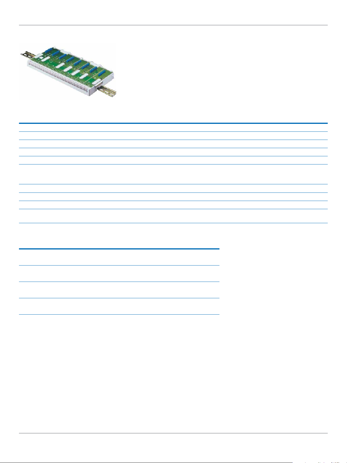
PAC8000 2/2 I/O Module Carriers
These module carriers are designed for 2/2 modules and are for either 32- or 64-module
addressing. If 64-slot addressing is required for a node, these carrier types must be used exclusively
as they cannot be mixed with 32-slot address carriers. A range of extender carriers and cables
allow for flexibility in cabinet design. Carriers can be mounted on T- or G-section DIN-rail or directly
to a flat surface, and may be joined end-to-end to extend the size of an installation.
Bussed Field Power (BFP) is connected to the I/O Module Carrier for modules that require this. Each
BFP connection supplies two adjacent module slots, so these modules must use the same BFP
supply. Terminals are provided on the Carrier to terminate cable screens and shields.
Field terminals are “clicked” in to place on the Carrier, then are trapped in place by inserting the I/O
Module and secured by the module’s screw.
I/O Module Carriers have no active components, so have very high reliability.
8707-CA-08 8710-CA-04
Product Name 8 Module Carrier 4 Module Carrier
Lifecycle Status Active Active
Module Addressing 1-32 1-32
Railbus Connectors
Weight (g) 680 350
Mounting
Dimensions (W x D x H) in mm 342 x 170 x 22 178 x 170 x 22
Common PAC8000 Specifications See Section 14 for System Specifications See Section 14 for System Specifications
Female In
Male Out
DIN-rail (T): 7.5 x 35 mm
DIN-rail (T): 15 x 35 mm
DIN-rail (G)
Flat Panel
Female In
Male Out
DIN-rail (T): 7.5 x 35 mm
DIN-rail (T): 15 x 35 mm
DIN-rail (G)
Flat Panel
PAC8000 SafetyNet
www.geautomation.com
Automation & Control Systems
5.67
Page 2
Safety and Distributed Control
Module Carrier
The 8-module carrier with extended addressing features:
• 64-slot address bus
• Accepts up to eight SafetyNet and/or standard I/O modules
• DIN-rail or panel mounting
• Carries control signals and data on Railbus
• Distributes System Power to modules
• Distributes Bussed Field Power to modules
• Isolated earthing bar for cable screens/shields
8709-CA-08
Product Name 8-module Carrier - extended addressing
Lifecycle Status Active
Electrical Connections
Railbus Connectors female in, male out
Cable Screens/shield Connections M4 screw terminals (x34)
8-pin male (x2) - The two 8-pin connectors provided at the top rear of
Bussed Field Power Supply Connectors
Dimensions (W x D x H) mm 342 x 170 x 22
Weight (g) 680
Mounting Methods Flat panel or DIN rail
DIN-rail types
the carrier connect power supplies for ‘field power’. These supplies are
routed through I/O modules that require power for their field circuits.
‘Top hat’ 35 x 7.5mm rail or 35 x 15mm rail to EN 50022
G-section rail to EN 50035
Bussed Field Power Connector
Terminal Function
1 I/O modules 1 & 2
2 –ve (or Neutral)
3 I/O modules 1 & 2
4 +ve (or Live)
5 I/O modules 3 & 4
6 +ve (or Live)
7 I/O modules 3 & 4
8 –ve (or Neutral)
Connector and Table
The table above gives the connection details for modules 1 to 4. The second connector provides identical connections for
modules 5 to 8.
Notes:
For applications with up to 4 IO Modules, it is possible to use the 4-module Carrier (8710-CA-04).
Automation & Control Systems
5.68
www.geautomation.com
Page 3

Safety and Distributed Control
PAC8000 SafetyNet
PAC8000 2/1 I/O Module Carriers
These module carriers are designed for 2/1 modules with Intrinsically Safe field wiring and are
for either 32- or 64-module addressing. If 64-slot addressing is required for a node, these carrier
types must be used exclusively as they cannot be mixed with 32-slot address carriers. A range of
extender carriers and cables allow for flexibility in cabinet design. Carriers can be mounted on T- or
G-section DIN-rail or directly to a flat surface, and may be joined end-to-end to extend the size of
an installation. Terminals are provided on the Carrier to terminate cable shields and screens.
Field terminals are “clicked” in to place on the Carrier, then are trapped in place by inserting the I/O
Module and secured in place by the module’s screw.
I/O Module Carriers have no active components, so have very high reliability.
2/1 modules do not employ Bussed Field Power as the 2/2 modules do. They draw all their field
power requirements from the System Power supply. The current drawn from the System Power
Supply is typically much higher on the 2/1 side of the node than on the 2/2 side. System Power from
the 2/2 side of the node does not pass through the Railbus Isolator, but is provided by one or more
8920-PS-DC IS Power Supplies mounted on the 2/1 side of the Railbus Isolator.
8727-CA-08 8729-CA-08 8720-CA-04
Product Name 8 Module Carrier 8 Module Carrier 4 Module Carrier
Lifecycle Status Active Active Active
Module Addressing 1-32 1-64 1-32
Railbus Connectors
Weight (g) 680 680 350
Mounting
Dimensions (W x D x H) in mm 342 x 170 x 22 342 x 170 x 22 178 x 170 x 22
Common PAC8000 Specifications See Section xx for System Specifications See Section xx for System Specifications See Section xx for System Specifications
Female In
Male Out
DIN-rail (T): 7.5 x 35 mm
DIN-rail (T): 15 x 35 mm
DIN-rail (G)
Flat Panel
Female In
Male Out
DIN-rail (T): 7.5 x 35 mm
DIN-rail (T): 15 x 35 mm
DIN-rail (G)
Flat Panel
Female In
Male Out
DIN-rail (T): 7.5 x 35 mm
DIN-rail (T): 15 x 35 mm
DIN-rail (G)
Flat Panel
www.geautomation.com
Automation & Control Systems
5.69
 Loading...