

GEC Plessey Semiconductors ZN409CE Datasheet
ZN409CE
PRECISION SERVO INTEGRATED CIRCUIT
The ZN409CE is a precision monolithic integrated circuit
designed particularly for pulse-width position servo mechanisms used in all types of control applications. The low
number of components required with the ZN409CE, together
with its low power consumption, make this integrated circuit
ideal for use in model aircraft, boats and cars where space,
weight and battery life are at a premium. The amplifier will
operate over a wide range of repitition rates and pulse widths
and is therefore suitable for the majority of systems. The
ZN409CE can also be used in motor speed control circuits.
FEATURES
■ Low External Component Count
■ Low Quiescent Current (7mA Typical at 4.8V)
■ Excellent Voltage and Temperature Stability
■ High Output Drive Capability
■ Consistent and Repeatable Performance
■ PrecisionInternal Voltage Stabilisation
■ Time Shared Error Pulse Expansion
■ Balanced Deadband Control
■ Schmitt Trigger Input Shaping
■ Reversing Relay Output (DC Motor Speed Control)
DS3894 - 2.0
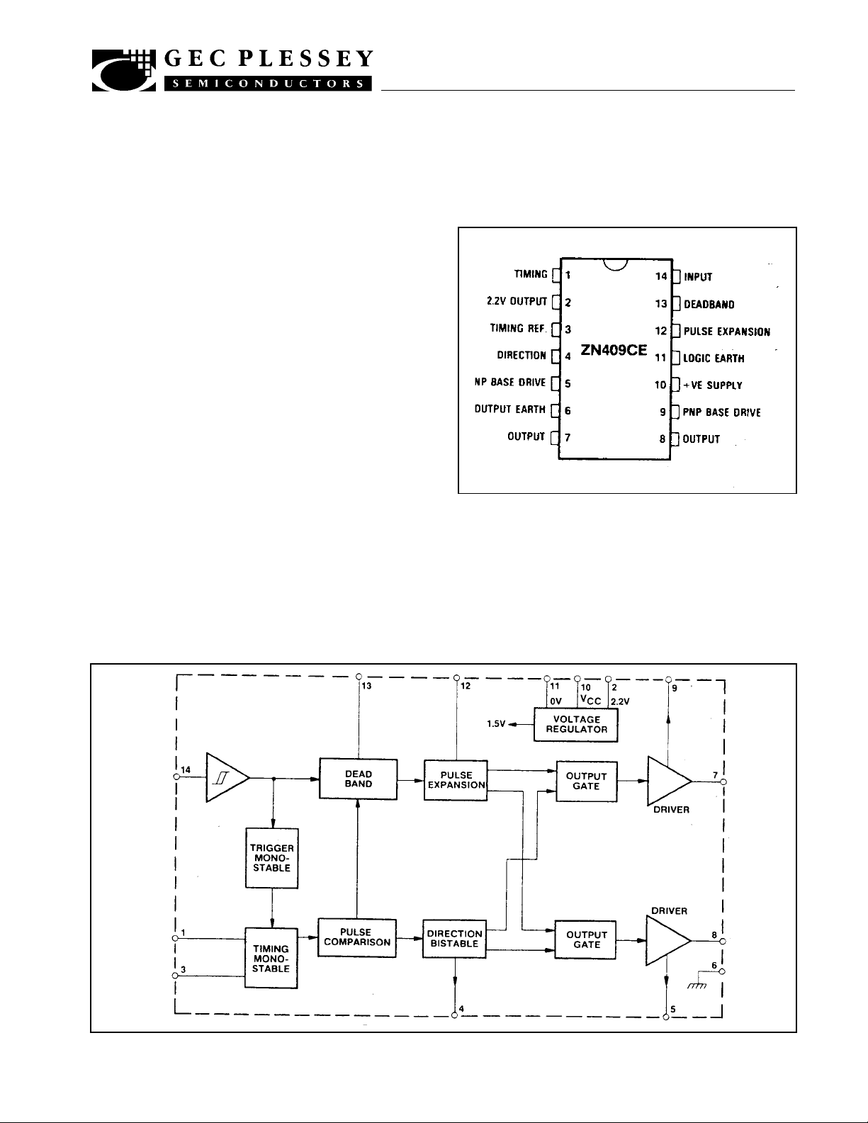
Fig.1 Pin connections - top view
ABSOLUTE MAXIMUM RATINGS
Supply voltage 6.5V
Package dissipation 300mW
Operating Temperature range -20°C to +65°C
Storage temperature range -65°C to +150°C
Fig.2 Block diagram for ZN409CE

ZN409CE
ELECTRICAL CHARACTERISTICS
Test conditions (unless otherwise stated):
Tamb = 25°C, VS = 5V
Characteristics
Input threshold (lower)
Input threshold (upper)
Ratio upper/lower threshold
Input resistance
Input current
Regulator voltage
Regulator supply rejection ratio
Monostable Linearity
Monostable period temperature
coefficient
Output Schmitt deadband
Minimum output pulse
Error pulse for full drive
Total deadband
PNP drive
Output saturation voltage
Direction bistable output
Supply voltage range
Supply current
Total external current from regulator
Peak voltage V
C EXT (with respect to 2V
regulated voltage)
Min.
1.15
1.4
1.1
20
350
2.1
200
-
-
±1
2.5
70
±3.5
40
35
-
2
3.5
4.6
1.3
-
-
Value
Typ. Max.
1.25
1.5
1.2
27
500
2.2
1.35
1.6
1.3
35
650
2.3
300
3.5
4.0
+0.01
±1.5
3.5
100
±5
55
50
300
2.8
5
6.7
±3
4.5
130
±6.5
70
65
400
3.6
6.5
10
-
0.7
0.5
Units
V
V
Pin 14
Pin 14
Test conditions
-10°C to +65°C
kΩ
µA
V
-
-10°C to +65°C, 1.3mA load current
S = 3.5V to 6.5V
V
dV
IN
RSRR = dVOUT
%
-
%/°C
± 45°, Rp = 1.5kΩ, R1 = 12kΩ
Excluding R
1 = 12kΩ (potentiometer slider set
R
T, CT. Rp = 1.5kΩ,
mid-way)
µs
ms
µs
CE = 0.47µF
E = 0.47µF, RE = 180kΩ
C
15ms repetition rate
CE = 0.47µF, RE = 180kΩ
µs
mA
mA
mV
D = 1000pF
C
T = 25°C
T = 10°C
L = 400mA
I
mA
V
mA
-
-
-
mA
V
V
Quiescent
S = 3.5V
V
T = 25°C
T = -10°C
CIRCUIT DESCRIPTION
The ZN409CE incorporates a precision dual voltage
source providing 1.5V for internal use and 2.2V for external
circuit requirements.
The input circuit is a Schmitt trigger allowing servo operation independent of edge speed, as obtained from the receiver-decoder.
Output from the Schmitt trigger is fed to the deadband and
monostable circuits. The deadband circuit prvides a
prgrammable area of insensitivity to input pulse in order to
eliminate hunting and overshoot. Dynamic feedback can be
2
used to reduce the width of the deadband to acceptable levels,
and to maintain correct servo operation.
The monostable circuits provide the inputs to the pulse
comparison circuit which determines direction and amount of
drive required to reach the new position. The output drive is
also controlled by the pulse expansion circuit. This circuit
ensures that a stationary motor will start rotating without
drawing full stall current. This gives much improved battery
life.
 Loading...