

GEC Plessey Semiconductors SL490B Datasheet

THIS DOCUMENT IS FOR MAINTENANCE
PURPOSES ONLY AND IS NOT
RECOMMENDED FOR NEW DESIGNS
0V AND XXX00
V
CC
(19V)
000XX
001XX
010XX
011XX
100XX
CARRIER TIME CONSTANT
REGULATED VOLTAGE, V
REG
PPM TIME CONSTANT
XXX01
XXX10
XXX11
111XX
110XX
101XX
1
2
3
4
5
6
7
8
9
18
17
16
15
14
13
12
11
10
SL490B
SELECTION
MATRIX
CURRENT
SOURCES
SELECTION
MATRIX
CURRENT
SINKS
SELECTION
MATRIX
CURRENT
SOURCES
OUTPUT
SL490B
REMOTE CONTROL TRANSMITTER
(Supersedes version in April 1994 Consumer IC Handbook, HB3120 - 2.0)
GPS has developed and produced a range of monolithic
integrated circuits which give a wide variety of remote control
facilities. As well as ultrasonic or infra-red transmission,
cable, radio or telephone links may also be used. Pulse
Position Modulation (PPM) is used with or without carrier and
automatic error detection is incorporated. Initially designed
with TV remote control in mind, the device is also suitable for
use in radios, tuners, tape and record decks, lamps and
lighting, toys and models, industrial control and monitoring.
The SL490B is an easily extendable, 32-command PPM
transmitter drawing negligible standby current.
FEATURES
■ Ultrasonic or Infra-Red Transmission
■ Direct Drive or Ultrasonic Transducer
■ Direct Drive of Visible LED when using Infra-Red
■ Very Low Power Requirements
■ Pulse Position Modulation gives Excellent Immunity
from Noise and Multipath Reflections
■ Single Pole Key Matrix
■ Switch Resistance up to 1kΩ Tolerated
■ Low External Component Count
■ On-Chip Anti-Bounce Circuitry
ABSOLUTE MAXIMUM RATINGS
Supply voltage, V
CC
Total power dissipation
Operating temperature range
Storage temperature range
210°C to 160°C
255°C to1150°C
19·5V
600mW
APRIL 1995
3056-1.3
DP18
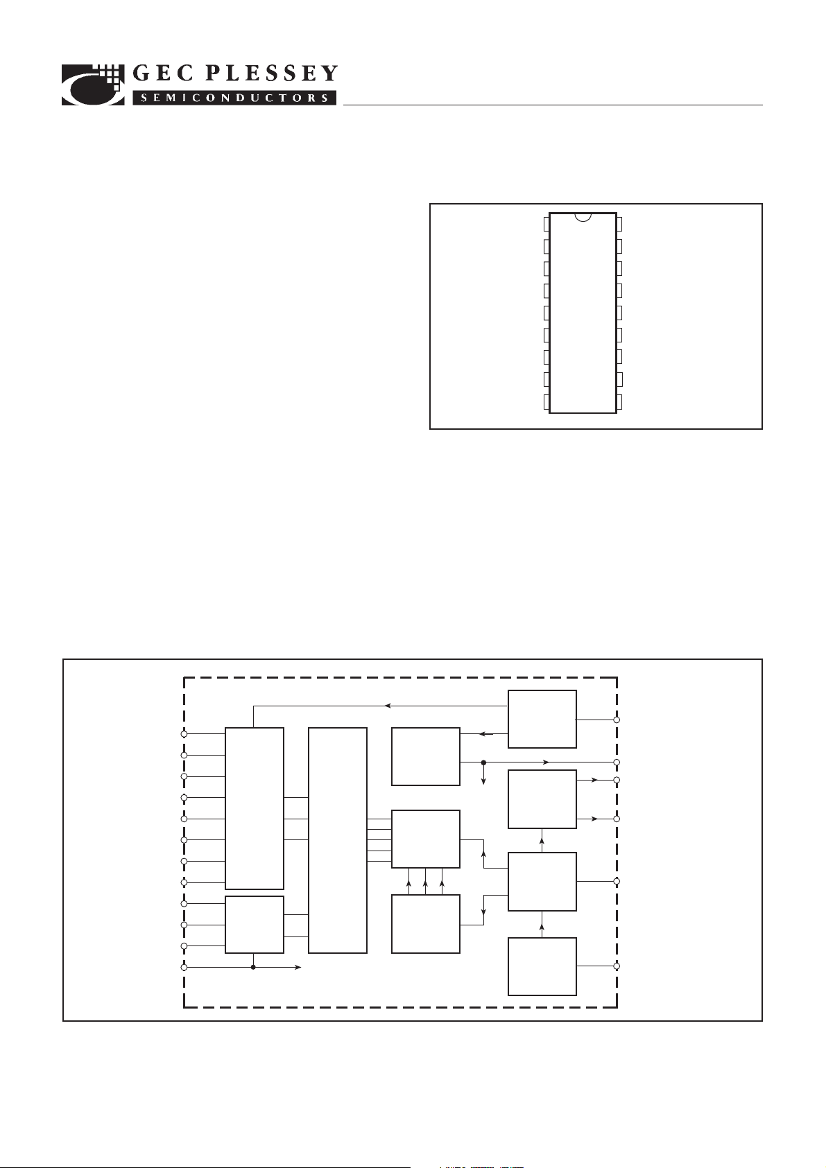
Fig. 1 Pin connections - top view
QUICK REFERENCE DATA
■ Power Supply: 9V Standby 6µA, Operating 8mA
■ Modulation: Pulse Position with or without Carrier
■ Coding: 5-Bit Word giving a Primary Command Set of
32 Commands
■ Key Entry: 8 3 4 Single Pole Key Matrix
■ Data Rate: Selectable 1Bit/Sec to 10kBit/Sec.
■ Carrier Frequency: Selectable 0Hz (No Carrier)
to 200kHz
ORDERING INFORMATION
SL490B NA DP
SWITCH
MATRIX
CURRENT
SOURCES
SWITCH
MATRIX
CURRENT
SINKS
5
6
7
8
9
10
11
12
13
14
15
1
ROW
ENCODER
COLUMN
ENCODER
0V
SUPPLY
SWITCH
AND
REGULATOR
CODE
REGISTER
MULTIPLEX
3-BIT
COUNTER
Fig. 2 SL486 block diagram
SWITCH
CURRENT
SELECTOR
OUTPUT
AMPLIFIER
PULSE
POSITION
MODULATOR
CARRIER
OSCILLATOR
4
V
CC
17
V
REG
2
PPM OUTPUT
3
16
PPM TIME CONSTANT
18
CARRIER TIME CONSTANT
 Loading...