

GEC Plessey Semiconductors SL1454NADP Datasheet

THIS DOCUMENT IS FOR MAINTENANCE
PURPOSES ONLY AND IS NOT
RECOMMENDED FOR NEW DESIGNS
SL1454
WIDEBAND LINEAR FM DETECTOR FOR SATELLITE TV
The SL1454 is a wideband FM demodulator designed to
operate with a carrier frequency between 70MHz and 150MHz.
The internal circuitry of the device is similar to that of the SL1452
except that the quadrature demodulator operates at the input
frequency.
FEATURES
■ Excellent Threshold
■ Negligible Differential Gain and Phase Errors
■
Video Bandwidth Suitable for High Definition TV
■ High Sensitivity and Wide Dynamic Range
■ Wide Operating Frequency Range: 70 to 150MHz
ORDERING INFORMATION
SL1454 NA DP (14-lead plastic DIL package)
ADVANCE INFORMATION
1
0V
0V
2
SL1454
3
4
DEMODULATOR COIL
DEMODULATOR COIL
Fig. 1 Pin connections - top view
ABSOLUTE MAXIMUM RATINGS
Operating temperature range
Supply voltage, pin 6
Input voltage, pin 7 or 8
Storage temperature
Junction temperature
8
INPUT SIGNAL
7
INPUT REF
6
V
5
VIDEO OUTPUT
2039-2·1
CC
DP8
210°C to180°C
7V
2·5V p-p
255°C to 1150°C
1175°C
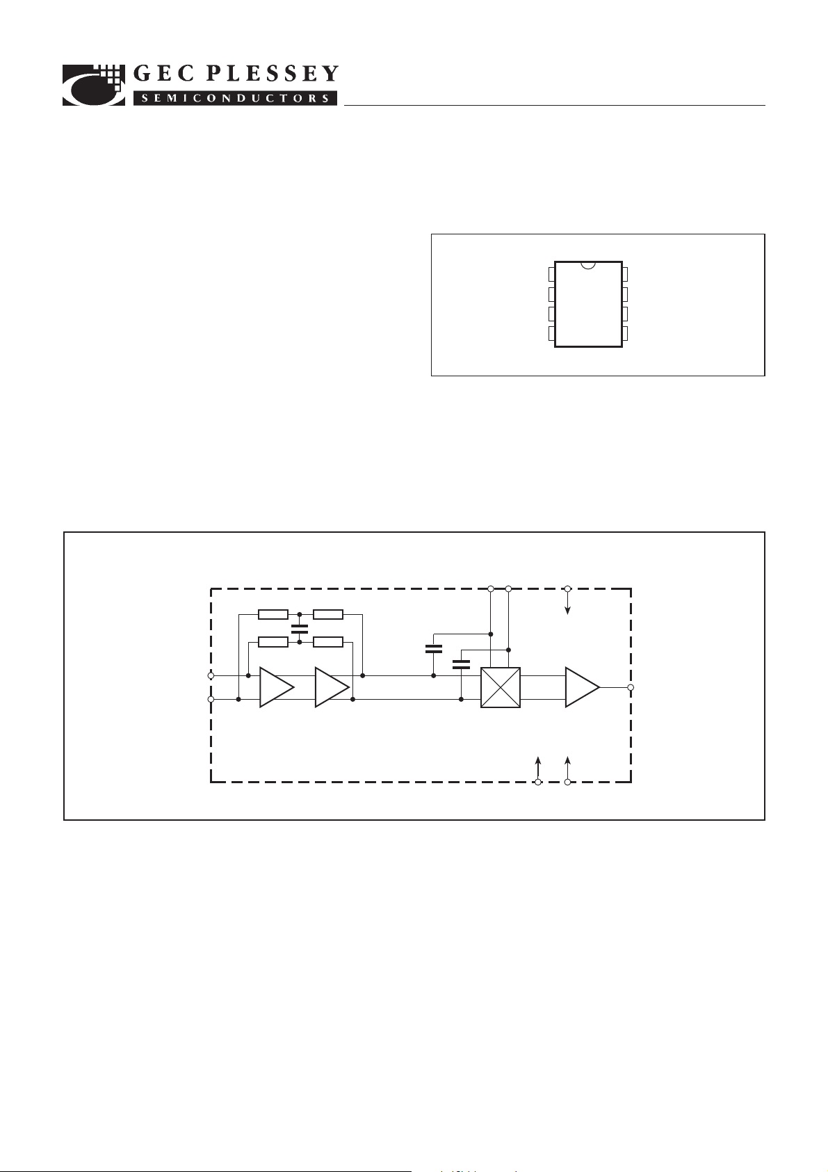
INPUT REF
INPUT SIGNAL
7
8
1k
1k
INPUT
AMPLIFIER
70p
2k
2k
Fig. 2 Block diagram
2p
QUADRATURE
DEMODULATOR
COMPONENTS
2p
DEMODULATOR
32
V
AMPLIFIER
1
0V40V
CC
6
VIDEO
5
VIDEO OUTPUT
SL1454
ELECTRICAL CHARACTERISTICS
These characteristics are guaranteed over the following conditions (unless otherwise stated):
T
= 125°C, V
AMB
= 14·5V to 15·5V, Q = 2, f = 140MHz
CC
Characteristic
Supply current, I
CC
Video output voltage
Video bandwidth
Minimum operating frequency
Maximum operating frequency
Input voltage
Intermodulation
Differential gain
Differential phase
Signal-to-noise ratio
23
Pin
6
5
5
8
8
8
5
Min.
10
Typ. Max.
30
35
0·4
10
70
150
300
250
Units
mA
V p-p
MHz
MHz
MHz
mVrms
dB
V
= 5V
CC
Df = 21·4MHz p-p
Product of input modulation: f = 4·4MHz,
Conditions
Df = 21·4MHz p-p and f = 6MHz, Df = 3MHz p-p
(PAL colour and sound subcarriers).
Value
5
,61
%
Df = 21·4MHz p-p. Demodulated staircase
referred to input staircase before modulation.
5
,61
deg
Demodulated colour bar waveform referred to
waveform before modulation.
5
70
dB
Ratio of output with Df = 21·4MHz p-p at 1MHz
to output rms noise in 10MHz bandwidth
with Df = 0.
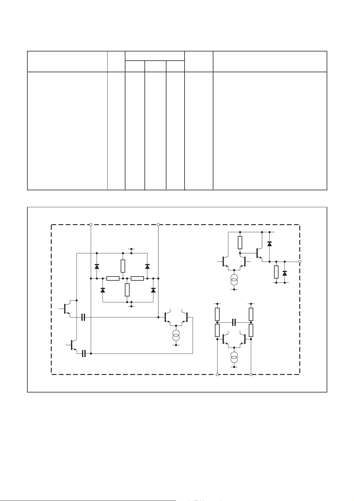
QUADRATURE COIL
15V
15V
1·75k
2p
2p
3·2k
400 400
1·8k
0V
2·5V 2·5V
2mA
0V
INPUT
SIGNAL
Fig. 3 Input/output interface circuits
640
2mA
0V
2k 2k
70p
1k 1k
3mA
0V
87
INPUT
REF
5
VIDEO
OUTPUT
0V
2
 Loading...