

Page 1

G340 INSTALLATION NOTES
(March 31, 2002)
Thank you for purchasing the G340 drive. The G340 DC s ervodrive is warranted t o be free of m anufac turing def ect s f or 1
year from the dat e of purchase. Also anyone who is dissat isfied with it or is unable to make it work will be cheerfully
refunded the purchase price if t he G340 i s returned within 15 days of the purchase date.
PLEASE READ FIRST BEFORE USING THE G340:
If you are not familiar with DC servodrives please do the following set up instructions with the motor on the benc h before
mounting it on the mechanism it will eventually run. This will allow you to get a baseline motor behavior of what to expect.
Before you start, you must have a suitable encoder mounted and properly aligned on the motor. Follow the manufacturer’s
instructions on m ounting and aligning the encoder if the motor doesn’t already come with one.
Next you must have a DC power supply suitable f or the motor. Do not use a power supply voltage m ore than 5 volts in
excess of the motors rat ed voltage. The power supply current rati ng must equal the maxim um current you expect to run
the motor at.
Finally have a STEP and DIRECTION pulse source available.
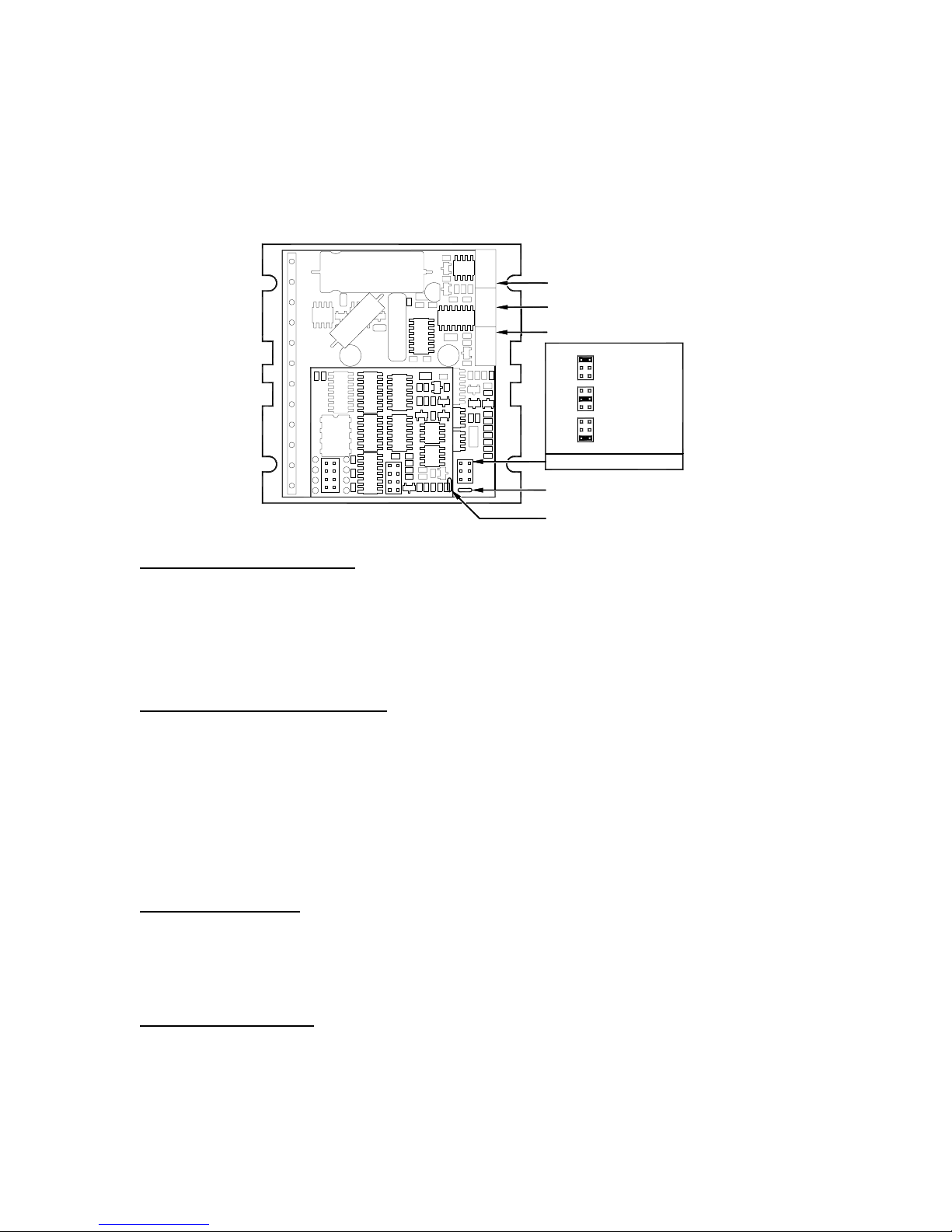
Before going on, t urn the c urrent LIMIT trim pot a quarter to half of full sc ale. Turn the GAIN t rimpot full y off and turn the
DAMPing trimpot to a quarter of full scale. The trimpots are single-turn, do not over-t orque them with a screwdriver.
REMOVING AND REPLACING THE COVER:
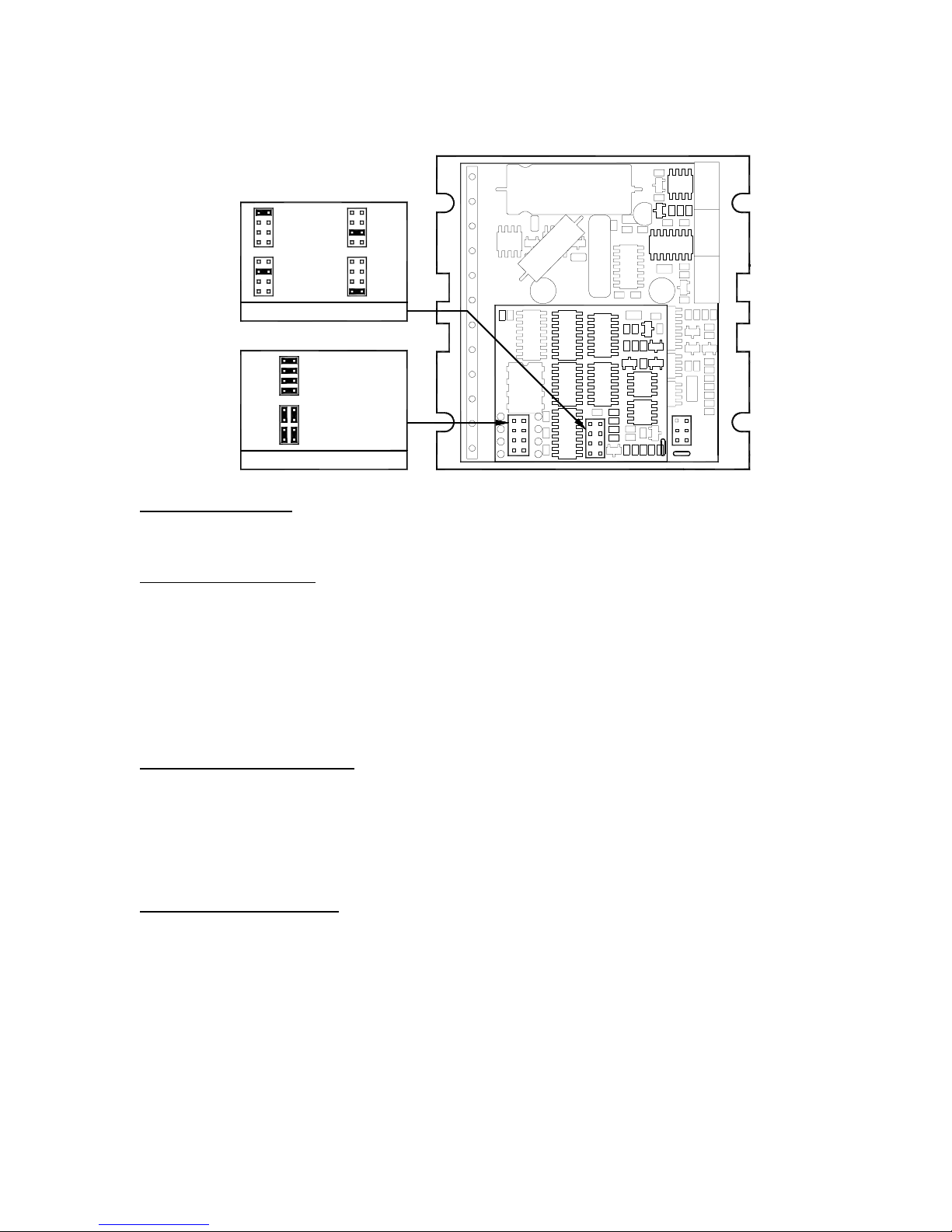
The STEP PULSE MULTIP LIER and the INPUT OPTI ON settings are jumpered internall y. It is nec essary to rem ove the
cover of the drive to change these s ett ings from t heir default values. Please fol low the steps below on how to remove and
replace the cover to avoid damagi ng t he dri ve:
REMOVING THE COVER:
1) Remove the two 2-56 phillips-head screws on the bottom of the drive.
2) Gently lift the back of the cover upward until the LED clears the rec tangular hole
3) Slide the cover backwards while still lifting until it clears the drive.
REPLACING THE COVER:
1) Make sure the LED is vertical rel ative to the drive printed circui t board.
2) Slide the cover forward over the drive while lifti ng the back of the cover.
3) When the cover is fully forward, look to see the LED is al i gned with the hole.
4) Gently press the cover down, mak i ng sure the LED moves into the hol e.
5) Replace the screws on the bottom of the drive.
It is recommended to use small needle-nos e pl i ers or tweezers to move the jumpers on the internal headers.
G340 MULTIPLIER AND INPUT OPTION HEADERS:
MULTIPLIER OPTION HEADER
The G340 has a built in STEP PULS E MULTIPLIER. This circuit puts out 1, 2, 5, or 10 pulses f or every i nput STEP pulse.
All motor moves will be in these increm ent s. For example, if X10 is selec ted, t hen the m ot or will move 10 encoder count s
for every STEP pulse sent t o the G340. Move the jumper on t he MULTIPLIER HEADER to s elect the desired multipl ier.
Do not operate the drive without a jumper.
INPUT OP TION HEADER
The INPUT OPTION HEADER allows the STEP and DIRECTION opto-isolators to be configured as either common
ground or common +5VDC.
If the G340 input s are driven by a sourc e that has only ground available, such as a PC parallel port , mo ve the 4 jum pers
on the header so t hat it l ooks like the COMMON GROUND set ting. Connect the input driver ground to TERM 12 on the
main connector.
If the G340 inputs are driven by open collec tor transistors or standard TTL gates, move the 4 jumpers on the header so
that it looks lik e the COMMON +5VDC setting.
1
Page 2
1
5
2
6
3
7
48
1
5
2
6
3
7
48
X10
X5
1
2
3
48
1
2
3
48
MULTIPLIER HEADER
5
6
X2
7
5
6
X1
7
1
5
2
6
COMMON GROUND
3
7
48
1
5
2
6
COMMON +5VDC
3
7
48
INPUT OPTION HEADER
G340 TERMINAL WIRING:
IMPORTANT: When first testing the G320, connect ERR/RES (term . 5) to ENC+ (term. 7).
Please follow the next steps in the sequence they are given.
STEP 1: ENCODER HOOK-UP
The encoder must be at m ini m um a 25 line-c ount digi tal quadrat ure encoder and m us t operat e on a si ngle +5VDC power
supply. If t he encoder supply current is more than 50 mA, use an external +5VDC s upply. It may have an I NDEX output,
which will not be used. If it has differential outputs , use only the “+” phase outputs. I MPORTANT: Connect a 470-ohm
resistor from TERM. 6 to TERM. 7 if an external power supply is used for the encoder.
(TERM. 6) ENC- Connect the encoder power supply ground to this terminal.
(TERM. 7) ENC+ Connect the encoder +5VDC to thi s terminal
(TERM. 8) PHASE A Connect the encoder phase “A” to thi s terminal
(TERM. 9) PHASE B Connect the encoder phase “B” to this terminal
STEP 2: POWER SUPPLY HOOK-UP
Keep the power supply leads short and use the largest wire gauge that will fit in the t erminals. If the lead length is m ore
than 18” use a 1000 uF capacitor acros s t he G340 power supply term i nals. Make s ure your power supply can provide the
peak current the motor may draw. The power supply volt age must be between 18 VDC and 80 VDC. The actual vol tage
should not be more than 5 volts hi gher than the motor’s rated volt age.
(TERM. 1) POWE R GROUND Connect the power supply ground to this terminal.
(TERM. 2) +18 TO 80 VDC Connect the power supply “+” to t hi s terminal
STEP 3: TESTING THE ENCODER
At this point the encoder s hould be tes ted f or func ti onalit y. I f you wish t o m onitor t he POS ITI ON ERROR t est point with a
voltmeter or oscilloscope, then remove the cover of the drive now. If you have a choice, pick the oscilloscope.
The POSITION ERROR test point shows the difference between the comm and position and the actual m otor position.
When both are the same, the voltage will be +5VDC. For every count the motor is c l ockwise of the command position, the
voltage will decrease by 0.04 volts. When it drops to 0.4 volts, the protection c ircuit takes over and resets the drive for 3
seconds. W hil e reset, the FAULT light is on.
For counter-clockwise posit ion errors the voltage will increase by 0.04 volt s f or every count until it reaches 9.6 volts when
again the protection circui t takes over as before.
VOLTMETER MONITORING: Place the red lead on t he test point and the black lead on the large blue capacitor lead
(GND) furthest from the main connector. Turn on the power supply. The FAULT light should be on for 3 seconds and t hen
2
Page 3
turn off. The voltmet er should read +5VDC. Turn the motor s haft clockwise VE RY slowly. The voltmeter reading should
decrease 0.04 volts f or every encoder count. When the reading reaches 0.4 volts, the red light will turn on and the voltage
will jump back to +5VDC. After 3 seconds the light will turn off. You may turn the motor shaft counter-clock wise as well.
The voltage will increase then by 0.04 volts per count until it reaches 9. 6 volt s and trips the protection circuit.
OSCILLOSCPE MONITORING: Set the s cope to 2 volts / cm vertical and about 1 millisec per cm horizontal. Zero the
trace to the bottom l ine on the screen. DC coupl e the input. Place t he probe on the test point and the ground clip to the
blue capacitor ground lead. Follow the steps i n VOLTMETER TESTING above.
CURRENT LIMIT TRIMPOT
DAMPING TRIMPOT
GAIN TRIMPOT
1
4
ANTI-DITHER
2
5
DISABLED
3
6
1
4
LOW-INERTIA
2
5
ENABLED
3
6
1
4
DIRECTION
2
5
INVERTED
3
6
OPTION JUMPER BLOCK
TEST POINT GND
TEST POINT
(UNDER MULTIPLIER BOARD)
STEP 4: CONTROL INPUT HOOK-UP
The control input group is the standard step motor drive STEP, DIRECTION and +5VDC lines. The STEP and
DIRECTION signal drivers m ust be TTL com pat ible and have edge t ransi tion t im es of 100 ns or fas ter. The +5VDC is the
opto-isolator common anode line and must be returned to the pulse source +5VDC supply.
(TERM. 10) DIR Connect the DI RE CTION line to this term i nal .
(TERM. 11) STEP Connect the STEP line to this terminal.
(TERM. 12) +5VDC Connect this terminal to the cont rol l er +5VDC power supply
STEP 5: TESTING THE CONTROL INPUTS
You may wish to test the functionality of these inputs. If you used an oscilloscope in the previous section, leave it
connected to the test poi nt. If you used a voltmeter, then remove it from the drive.
Set the STEP puls e generator to about 40 pulses per s econd and set the DIRECTION out put to clockwise (logic al “1”).
Turn on the power supply. After the power-on reset period of 5 seconds t he FAULT light will turn off.
If you are using an oscilloscope, then the test point voltage will begin to increase until 3 seconds later it trips the protection
circuit at 9.6 volts. The FAULT light will turn on for 5 seconds and voltage will snap back to +5VDC. After the FAULT turns
off, the sequence will repeat again.
If you are not using an oscilloscope, jus t see if the FAULT light turns on and off every three seconds.
STEP 6: MOTOR HOOK-UP
Make sure the power is off and the STEP pulse source is set to zero pulses per second. Check to see if the trimpot
settings are set according to the instructi ons on page 2. You may wish to secure t he motor so it can’t jump off the bench.
(TERM. 3) ARM- Connect the RED motor lead to this terminal.
(TERM. 4) ARM+ Connect the BLACK motor l ead to this terminal.
STEP 7: TUNING THE SERVO
Turn on the power supply. The FAULT light should turn of f after 3 seconds. I f everything is correct you should hear the
motor “singing”. This is norm al . The motor is di t heri ng or bouncing between adjacent encoder counts. The i ntegral term in
a PID loop has infinite DC gain over time and will amplify even the smallest position error. Because encoder feedback can
only occur on count edges, the l oop is “blind” until it encounters an encoder count edge. It t hen reverses the motor
direction until another edge is found, then the process repeats .
3
Page 4
If the motor jumps slightly and the FAULT light immediately turns back on, then either the motor is wired backwards or the
trimpots are mi sadj ust ed. Chec k t he trim pot s ett ings. If they s eem right then switch the motor leads and try again. If it still
doesn’t work and you followed all the previous st eps, call me at the number at the end of this document.
Now turn on your STEP pulse s ource and ramp the speed up to see if t he motor turns. It s hould turn clockwise with a
logical “1” on the DIRECTION input .
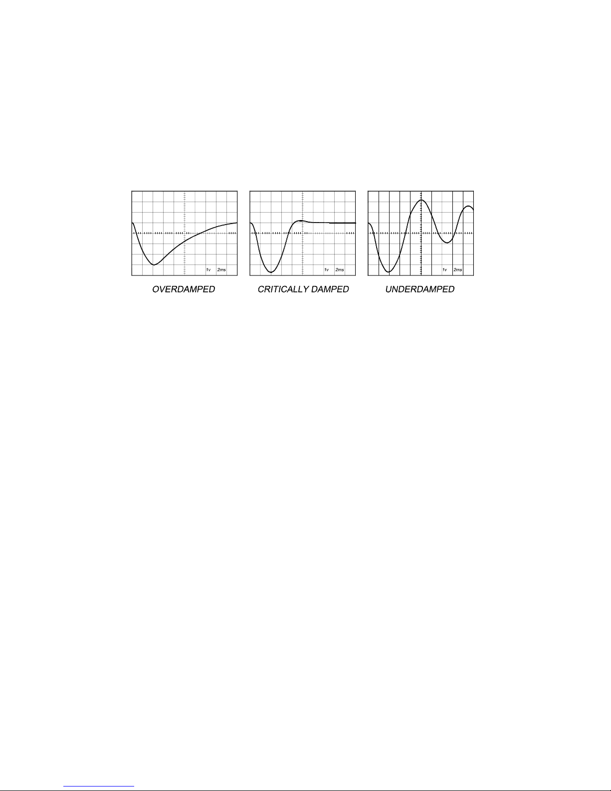
The optimum way to tune the servo is to induc e an impulse load on t he motor while watching an oscilloscope to see how
the motor behaves in response, then adjusting the PID co-eff icients (GAIN and DA MPING trimpot settings) for opt imal
behavior.
In all cases the motor must return to the command position, what matters is how it does it. The manner in which the motor
returns to its com mand position is called dampi ng. At one extreme called overdamped response, t he motor returns to
position after a long, drawn out delay. At the other extreme called underdamped response, the motor returns to its position
too rapidly, overshoots, ret urns and undershoots and so on until it finally s ettles at its comm and position. This is also
caused ringing; when extreme, the over/undershoot builds in am plitude until t he motor ent ers violent osc illation. Between
the two extremes is the optim al res ponse c alled c rit ic al damping. Here the motor rapidly returns to its posit ion with littl e or
no overshoot in the minimal amount of tim e.
GAIN AND DAMPING
GAIN and DAMPING settings generally track each other. If you increase GAIN (greater stiffness), then increased
DAMPING is needed as well to restore c ritical damping. Be careful, increas ing GAIN without increasing DAMPING may
cause the motor to break out into violent oscillation.
The higher GAIN is set, the noisier the mot or will be when stopped. This is because higher gain causes m ore vigorous
dithering between encoder counts at rest . There is a t rade-off between high gain (high s tiff ness) one hand and excessive
dithering (noise and motor heati ng) on the other. Use judgment here.
To see how your servo is compens ated it is first necessary t o induce a disturbance. The easiest way is to s witch the
DIRECTION input while comm anding a constant speed via the STEP i nput. The abrupt direction change puts just the
momentary load needed on the motor while you watch how it responds.
If you are using an oscilloscope, use channel 1 on the test point and channel 2 on the DIRECTION input. Set the trigger to
“normal”, trigger source t o channel 2 and trigger edge to “+”. You should see a s ingle sweep for every clockwise change
in direction.
Slowly increase STEP speed unti l you get a picture similar to one of the three above, and then do the following:
1) OVERDAMPED: Decrease DAMPING or i nc rease GAIN
2) CRITICALLY DAMPED: Do nothing; you’re there
3) UNDERDAMPED: Decrease GAIN or increase DAMPING
(POSITION ERROR TEST POINT NOTE)
Don’t confuse the POS ITION ERROR with the motor or m achine position. The s ignal is actually the dif ferential position
error between the comm and speed and the motor speed. As not ed above, sending clockwise STE P pulses moves the
POSITION ERROR voltage m ore positive while turni ng the mot or cloc kwise moves the POS ITION ERROR vol tage more
negative.
When the motor encoder counts match the num ber of STEP pulses being sent one for one, the POSI TION ERROR
voltage stays at +5VDC. I f the mot or gets ahead of the S TEP pulses such as during very rapi d deceleration, t he voltage
will decrease by 0.04 volts for every encoder count the motor is ahead of the STEP pulses s ent. The PID algorithm will
force the motor to match the STEP input over time and restore the POSI TION ERROR voltage back to +5 VDC.
4
Page 5

CURRENT LIMIT
The current LIMIT trimpot s ets m aximum c urrent t he m otor is perm it ted t o have. I t is adjus table f rom 0 am ps t o 20 am ps.
Normally the LIMIT trim pot is set to maximum (20 amps) unless you want to li mit motor torque to a l ower value.
Motor speed and posit ion is unaffected by t he current LIMIT sett ing unless the torque dem and due to load exceeds this
setting, then the motor pos it ion will fall behind the command position because of ins ufficient torque.
FAULT INDICATOR
The FAULT indicator is on while the drive is in power-on reset, the DISABLE input is held “low” or if the protection circuit is
tripped due to a fault condition. All power MOSFETs are turned off and all internal counters are restet. The FAULT
condition lasts for 3 s econds, and then self-resets to try again. If the protection circuit tripped it and the cause is not
cleared, then it will immediately re-enter t he FA ULT state again and repeat the cycle.
There are two conditions that will trip the protec tion circuit . One condition is if a short-circ uit occurs and c urrent exceeds
20 amps. The other condition i s i f the P OSI TION E RROR exceeds +/- 120 c ounts caus ing a break of the servo-lock . This
condition can have several caus es:
1) The loop settings are severely under-damped and the motor breaks out into oscillation.
2) Excessive motor load due to acceleration or workload.
3) The speed command in excess of what the motor can deliver.
4) The current LIMIT is set too low.
5) The power supply current is insuffi cient for the demand.
6) The power supply voltage is below 18 VDC.
7) The motor is wired backwards, is broken or disconnected.
8) Encoder failure.
REVERSING DEFAULT MOTOR DIRECTION
The G340 will turn the m otor in t he CW direction when the DIRECTION input is “high” (logical “1”, or +5VDC). If ins tead
CCW is preferred, t hen:
1) Reverse the motor “+” and “-“ leads (term. 3 with term. 4)
2) Reverse the encoder “channel A” and “channel B ” l eads (term. 8 with term. 9)
USING THE G340 WITH VERY SMALL MOTORS
Very small motors have low induct ance relat ive t o their operating c urrent. Cons equently ripple c urrent due to puls e-width
modulation can quickly overheat and dest roy these motors. If the G340 will be used with these motors, then an external
low pass filter must be used to attenuate ripple current t o tolerable levels.
A suggested filter consists of two 150 microhenry inductors in series with each motor lead and a 2 microfarad, low
inductance film capacitor across the motor leads. The inductors must be rated for the anticipated peak motor current.
This filter is also need i f i ronless -arm ature or “panc ake” motors are used. These m otors have very low induct ance as well
and will overheat if driven directly by the G340.
(TERM. 5) ERR / RES
This terminal functi ons as an ERROR output and as a RESET input. Because this terminal functions as both an input and
an output, some detail ed description is necess ary.
When first testing the G340, ERR/RES (term. 5) was c onnected to ENC+ (term. 7). It can be lef t that way if it is not
necessary to read the stat e of the ERROR output. Otherwise, the f ol l owing detai l s are important.
The ERROR output is lat ched in t he “ERROR” s tat e (term . 5 = “0”) by the power-on reset ci rcuit ry in the G340. I t will stay
in this state indefi n i t el y until it is cleared by applying +5V to this terminal f or at l east 1 second.
The voltage on this terminal is +5V DC when the G340 is f unct ioning norm al ly. The vol tage on thi s t erm inal goes to 0V DC
whenever the FAULT indicator is lit. Thi s output can be used to signal your c ontroller that an error has occurred.
Normally when the G340 is first powered up, it will be necessary to push t he mom entary switch to START for 5 seconds.
This will clear the power-on reset condition and extinguish the FAULT LED. The m otor will then be enabled and the drive
will begin to operate. If at anytime aft er that a conditi on occ urs t hat c auses the G340 to “fault out”, such as not being able
to complete a step command, t he E RR/ RES terminal will go to “0”, signaling the com puter an error has occurred. This will
require the operator to correct the problem that caused the fault and then push the s witch to “START” for 5 seconds to reenable the G340.
5
Page 6
OPTIONAL
EXTERNAL
FAULT LED
CIRCUIT
TO COMPUTER
MOMENTARY
CENTER OFF
PN2907
5V
START
STOP
5V
LED
220
4.7 uF
1MEG
5V
FAULT
LED
TERM. 5
ERR/RES
470
470
FROM FAULT
DETECTORS
(FAULT=0)
RESET FOR
INTERNAL CIRCUIT
(RESET=1)
10K
G320 DRIVE
At anytime the operator c an push the switch to the “STOP” posi tion to immediatel y hal t the G340 drive. Anytime the G340
is in the “FAULT” s tate (FAULT LED lit), all switching action stops and the motor f reewheels and is unpowered. This will
light the “FAULT” light.
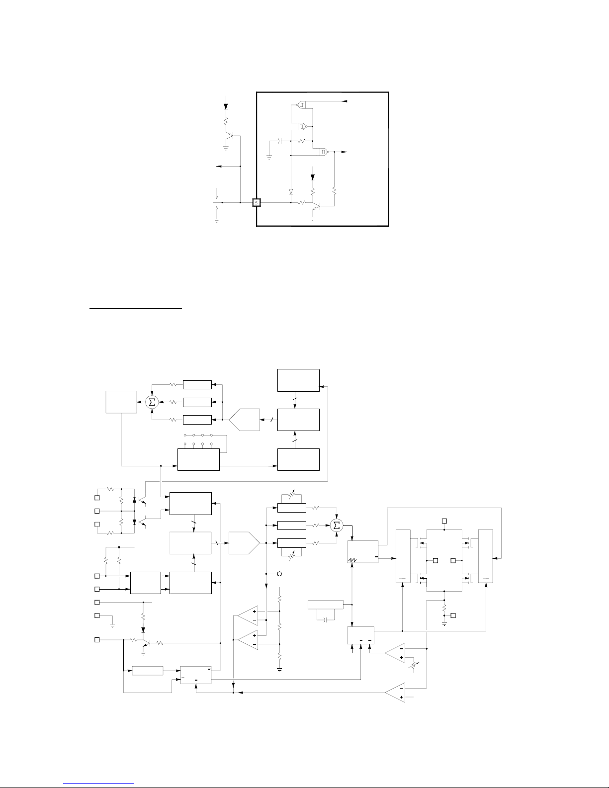
G340 BLOCK DIAGRAM:
DIFFERENTIA L
VOLTAGE
CONTROLLED
OSCILLATOR
200
11
1K
12
1K
10
200
+5VDC
1K 1K
8
9
7
6
5
CH A
QUADRATURE
DECODER
CH B
+5VDC
470
FAULT LED
470
10K
5 SECOND DELAY Q
PROPORTIONAL
DIVIDE BY 1, 2, 5, 10
CLOCK
CLOCK
8-BIT U/D COUNTER
U/D
8-BIT ADDER
U/D
8-BIT U/D COUNTER
CLOCK
S
FAULT LATCH
R
INTEGRAL
8
A
B
8
R
OUTPUT
R
A+B
R
Q
12510
8
4-BIT D/A
CONVERTER
8-BIT D/A
CONVERTER
POSITION ERROR
WINDOW COMPARATOR
4-BIT DOWN COUNTER
4
A+B
4-BIT UP COUNTER
CLOCK
DIFFERENT IAL
INTEGRAL
PROPORTIONAL
TEST POINT
+5VDC
4
A
4-BIT ADDE R
B
4
CLOCK
DAMPING
GAIN
25 KHZ OSCILLATOR
G340 BLOCK DIAGRAM
2
ANALOG
Q
BRIDGE
PULSE WIDTH
MODULATOR
CLK
CURRENT LIMIT
RD
"1"
DRIVER
IN
Q
OFF OFF
34
.025 Ohms
1
Q
R
CURRENT
LIMIT SET
OVER CURRENT LI MIT
BRIDGE
DRIVER
IN
6
Page 7
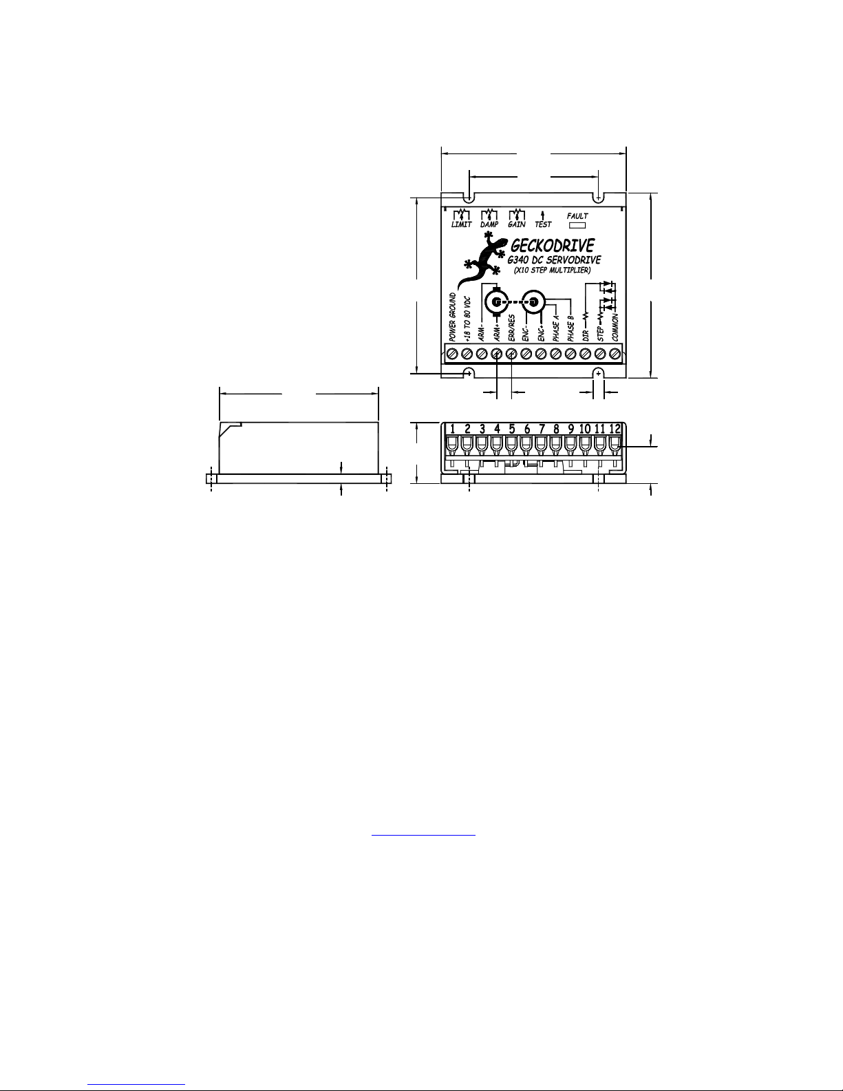
G340 Servodrive
2.5000"
(63.5 mm)
1.7500"
(44.5 mm)
(X10 Step Multiplier)
Cover:
Plate:
Aluminum, Anodized
Aluminum, Hard Anodized
Color: Black, Green Text
Weight:
Size:
3.6 oz (100 gm)
2.5" X 2.5" X 0.825"
2.3750"
(60.3 mm)
(63.6 X 63.5 X 21 mm)
2.1500"
(54.6 mm)
0.125"
(3.2 mm)
G340 SPECIFICATIONS:
Power Supply 18 to 80 VDC
Motor Current 0 to 20 Amps
Lock Range +/- 128 count following error
Feedback Quadrature TTL Encoder
Feedback Resolution X4 Encoder Line Count
Switching Frequency 25 kHz
Current Limit 0 to 20 Amp, Trimpot Adjustable
Analog PID Damping and Gain Trimpots
Step Pulse Frequency 0 to 250 kHz
Step Pulse “0” Time 0.5 Microseconds Min.
Step Pulse “1” Time 3.5 Microseconds Min.
Multiplier Settings X1, X2, X4, X5 and X10
Size 2.5" X 2.5” X 0.825"
Weight 3.6 oz weight
Encoder Supply +5VDC, 50 mA max
Geckodrive Inc. Phone: 1-714-771-1662
9702 Rangeview Drive Fax: 1-714-771-4867
Santa Ana, CA 92705 Web Site: www.geckodrive.com
0.8250"
(21 mm)
0.2000"
0.1500"
(3.8 mm)(5 mm)
2.5000"
(63.5 mm)
0.5000"
(12.7 mm)
7
 Loading...