

Page 1
in.xe
TM
innovative spa pack platform
Versatile
Easy to install
Watertight
TechBook
Page 2

in.xe TechBook
Table of contents
Warnings ............................................................................................................................................................... 2
Introduction ......................................................................................................................................................... 3
Features ................................................................................................................................................................. 4
Overview .............................................................................................................................................................. 5
in.xe dimensions: ................................................................................................................................................ 5
in.k200 dimensions: ........................................................................................................................................... 6
in.xe installation
- Floor installation procedure ................................................................................................................ 6
- Wall installation procedure .................................................................................................................. 7
in.k200 installation & connections
- Installing the in.k200 ............................................................................................................................. 8
- Connecting the main keypad to the in.xe spa pack .......................................................................... 8
in.xe connections
- Electrical wiring for North American model of the in.xe .................................................................. 9
- Electrical wiring for North American or CE model of the in.xe ........................................................ 9
- Heater connections ............................................................................................................................. 11
in.k200 keypad overview
- Function description .......................................................................................................................... 28
- Instructions .......................................................................................................................................... 28
- Typical settings .................................................................................................................................... 30
in.xe error codes
- in.xe error codes summary ................................................................................................................. 31
- Hr error message / step-by-step ....................................................................................................... 32
- Prr error message / step-by-step ....................................................................................................... 32
- HL error message / flow chart & step-by-step ................................................................................. 33
- FLO & UPL error message / flow chart & step-by-step ................................................................... 35
- OH error message / flow chart & step-by-step ............................................................................... 37
Troubleshooting
- Pump 1 doesn't work / flow chart & step-by-step ........................................................................... 38
- Pump 2 or blower doesn't work / flow chart & step-by-step ....................................................... 40
- Circulation pump doesn't work / flow chart & step-by-step ......................................................... 42
- Ozonator doesn't work / flow chart & step-by-step ....................................................................... 43
- Nothing seems to work / flow chart & step-by-step ....................................................................... 44
- Spa not heating / flow chart & step-by-step .................................................................................... 45
- Keypad doesn't seem to work step-by-step ................................................................................... 46
GFCI trips ............................................................................................................................................................ 47
Step-by-step field replacement procedure .................................................................................................. 48
How to replace the heater ................................................................................................................................ 51
Specifications ..................................................................................................................................................... 53
11
Page 3

in.xe TechBook
Warnings
WARNINGS:
Before installing or connecting the unit, please read the following.
* FOR UNITS FOR USE IN OTHER THAN SINGLE-FAMILY DWELLINGS, A CLEARLY LABELED
EMERGENCY SWITCH SHALL BE PROVIDED AS PART OF THE INSTALLATION. THE SWITCH SHALL
BE READILY ACCESSIBLE TO THE OCCUPANTS AND SHALL BE INSTALLED AT LEAST 5' (1.52 M) AWAY,
ADJACENT TO, AND WITHIN SIGHT OF THE UNIT.
* ANY DAMAGED CABLE MUST BE IMMEDIATELY REPLACED.
* TURN POWER OFF BEFORE SERVICING OR MODIFYING ANY CABLE CONNECTIONS IN THIS UNIT.
* TO PREVENT ELECTRIC SHOCK HAZARD AND/OR WATER DAMAGE TO THIS CONTROL, ALL
UNUSED RECEPTACLES MUST HAVE A DUMMY PLUG.
* THIS CONTROLLER MUST NOT BE INSTALLED IN PROXIMITY OF HIGHLY FLAMMABLE MATERIALS.
* LOW VOLTAGE OR IMPROPER WIRING MAY CAUSE DAMAGE TO THIS CONTROL SYSTEM. READ
AND FOLLOW ALL WIRING INSTRUCTIONS WHEN CONNECTING TO POWER SUPPLY.
* THIS PACK CONTAINS NO SERVICEABLE PARTS. CONTACT AN AUTHORIZED SERVICE CENTER FOR
SERVICE.
* ALL CONNECTIONS MUST BE MADE BY A QUALIFIED ELECTRICIAN IN ACCORDANCE WITH THE
NATIONAL ELECTRICAL CODE AND ANY STATE, PROVINCE OR LOCAL ELECTRICAL CODE IN
EFFECT AT THE TIME OF THE INSTALLATION.
Aeware®, Gecko®, and their respective logos are Registered Trademarks of Gecko Alliance Group.
in.xe™, in.access™, in.touch™, in.k200™, in.flo™, in.put™, in.seal™, in.link™, in.t.cip™, in.stik™, heat.wav™
and their respective logos are Trademarks of Gecko Alliance Group.
All other product or company names that may be mentioned in this publication are tradenames,
trademarks or registered trademarks of their respective owners.
2
Page 4
in.xe TechBook
Introduction
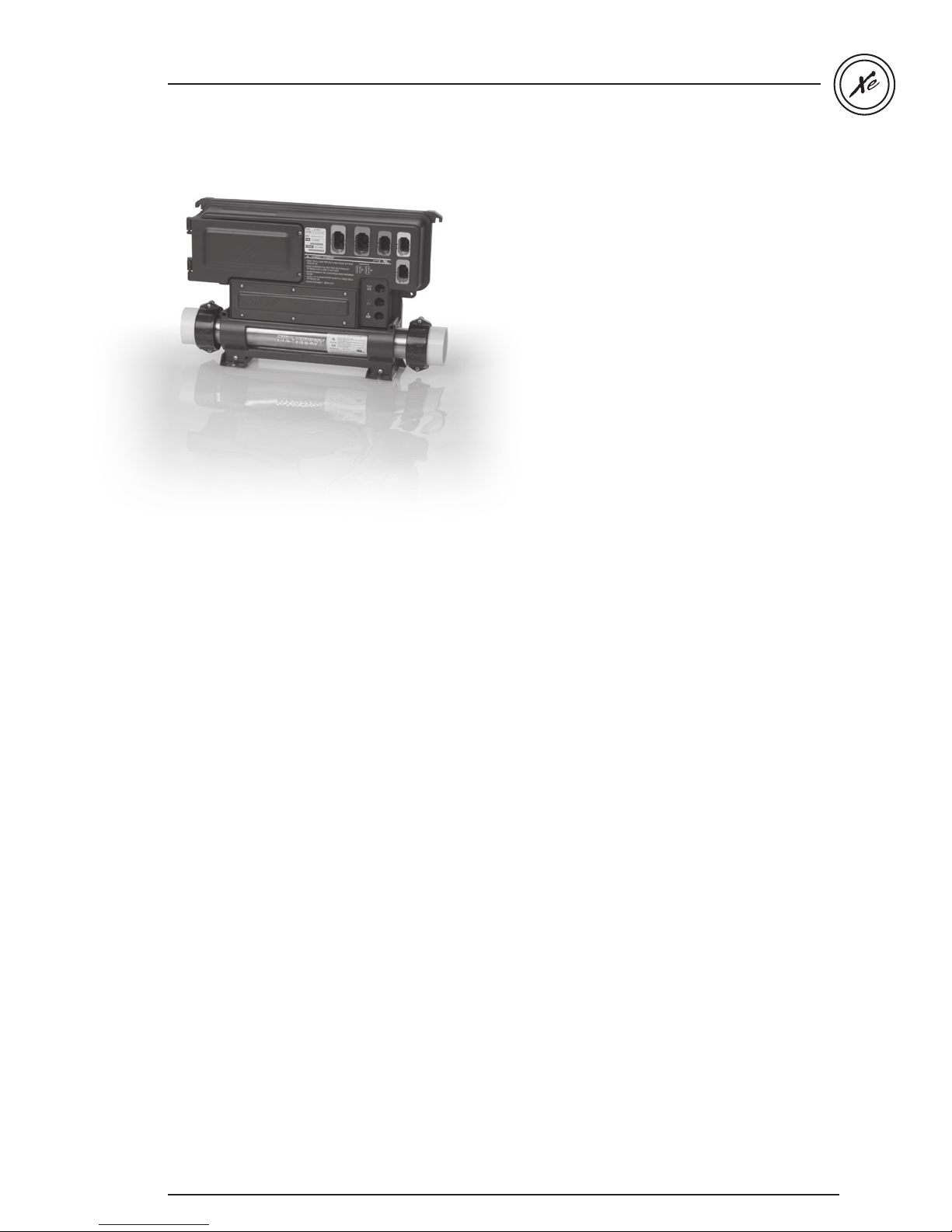
in.xe
Entry-level spa system
Congratulations! You have purchased one of the finest
entry-level spa packs available.
To install, use and enjoy your in.xe spa system take
the time to carefully read these instructions.
The in.xe has been designed for these typical spa
configurations:
• Single pump system
• Dual pump system
• Pump & blower system
• Dual pump & blower system
The in.xe can be wall-mounted or installed on its
mounting base and comes with an integrated heat.wav
water heater.
3
Page 5

in.xe TechBook
Features
The in.xe system boasts a long list of technical features. Each of them contributes to bringing the most advanced
solutions available to in.xe equipped spa owners:
in.put
input terminal block
The in.put was designed to ease wire insertion
(up to # 4 AWG) and connections. Tighter input
connection reduces heat generated for increased
component lifetime.
in.seal
watertight protection
The in.seal provides an extra level of protection
against water infiltration. Connectors and
power box are designed to be watertight so no
water can be in direct contact with electrical
components (IPX-5).
in.axess
board access prevention
Electronic components are placed into separate
and inaccessible compartments. Only serviceable
parts are made accessible to service technicians.
in.link
ingenious plugs and connectors
in.flo
dry-fire protection
A heater safety system located on the heat.wav
heater with an all-electronic dry-fire protection.
in.t.cip
water temperature algorithm
in.t.cip is an intelligent water temperature refresh
algorithm that calculates optimal time to start
pumps and get water temperature readings.
in.t.cip continuously readjusts the heater start time.
in.kin
kinetic heat monitoring
First ever UL approved kinetic heating protection
manages water temp increase generated by pump
heat dissipation. Hardware protection shuts all
accessories off if it senses water overheating.
in.stik
automated software upload
in.link cables are output and input plugs and
connectors that come with colored and tagged
polarizers. Totally waterproof, they are designed
to be easily configured and to ensure that all
cables of equipment used to make a spa or hot
tub work properly are well connected at their
intended connection port, eliminating any risk of
miswiring.
The in.stik is a pen drive with an in.link
connector very similar to a USB memory stick.
It connects to the spa pack and contains data
to program or configure its system. The system
executes the data upload automatically.
4
Page 6
in.xe TechBook
Overview
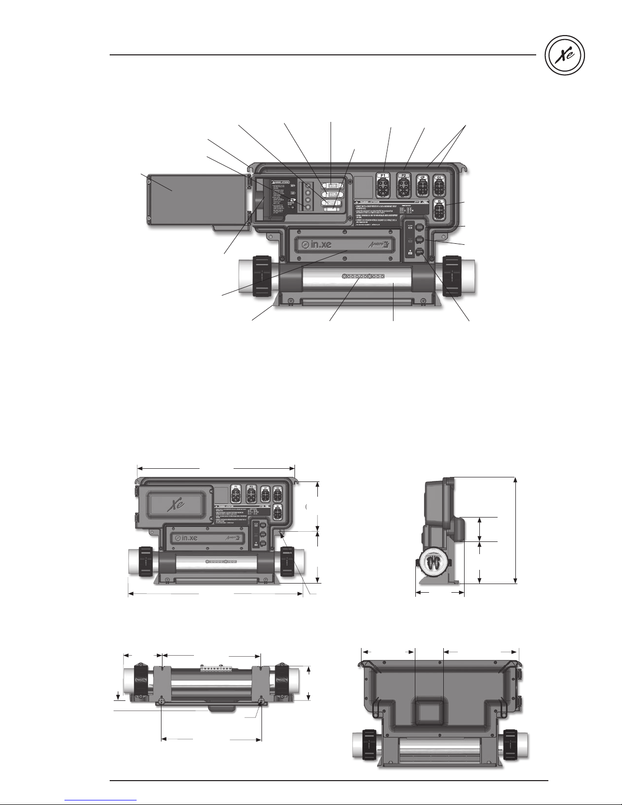
Accessory fuse Pump 2 fuse Pump 1 fuse
Installation brackets
Transformer fuse
Main power
Door to access
entry connection
power input
connectors
and fuses
Main power
cable input entry
Access to heater
connections
Mounting feet
Bonding lug
Note: No connectors should remain unplugged. Use blank plugs to fill unused connectors.
Pump 1
connector
heat.wav heater
* Pump 2
connector
2 connectors for
outputs controlled by
independent relays (for
ozonator, CP, light, blower
or any other accessories)
(120/240 V 5 A).
*Only one output is available on
IN.XE-3
Connector for direct
120/240 V 5 A output
(for audio or accessories)
Main keypad connector
Communication
connector (in.stik)
Light 12 V AC
connector (1 A max)
* Only available on IN.XE-5
in.xe dimensions:
4.2"
(106.7 mm)
1.2"
(30.5mm)
Front view
17.38"
(441.5 mm)
19.32"
(490.7 mm)
Bottom view
10.8"
(275.6 mm)
(6 mm)
11.0"
(279.4 mm)
Ø.25"
4x
5.51"
(140 mm)
5.69"
(144.5mm)
.9"
3
(98.3 mm)
Ø.25"
(6 mm)
Side view
(136.4 mm)
Rear view
6"
(152 mm)3"(76 mm)
5.37"
(69.9mm)
4.5"
(114.3 mm)
8.3"
(210 mm)
2.75"
11.75"
(298.5 mm)
5
Page 7
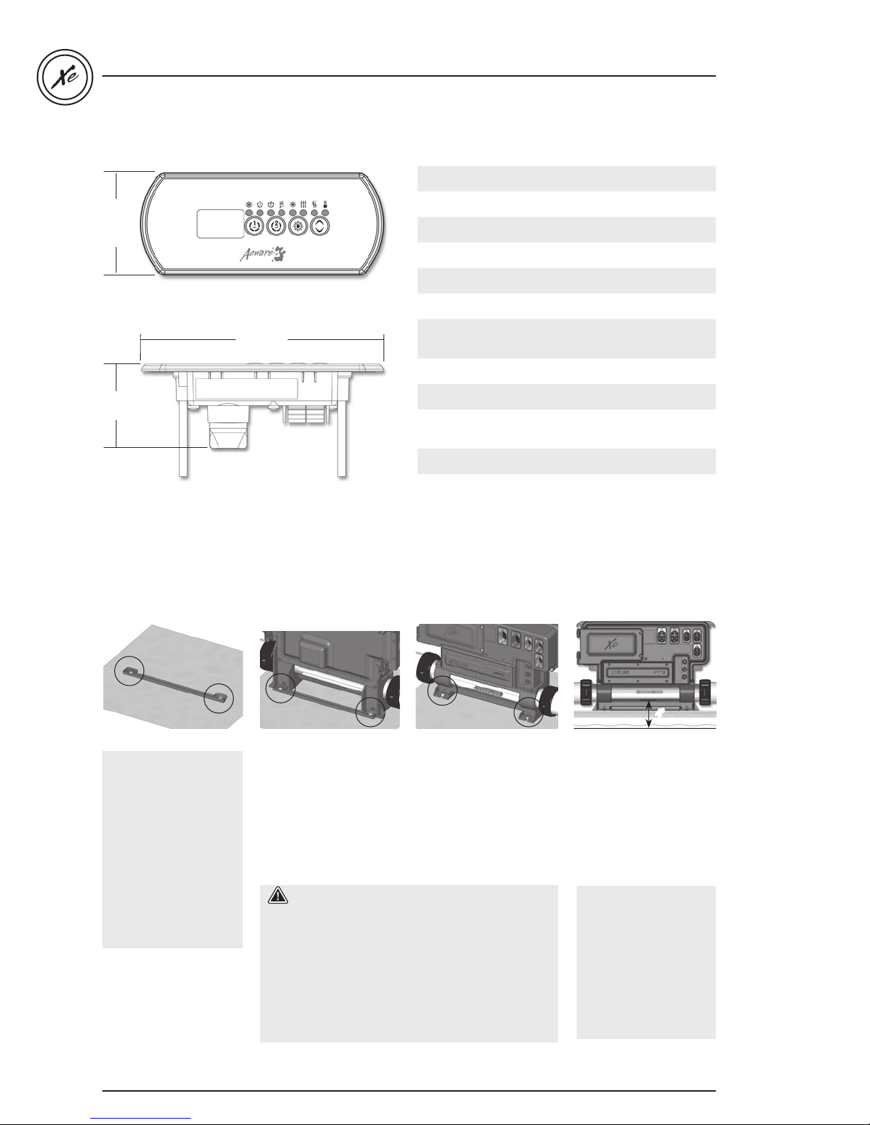
in.k200 dimensions:
in.xe TechBook
Features:
2"
(51 mm)
4.75"
(120 mm)
1.7"
(43 mm)
in.xe installation
Floor installation procedure
LED display
4 Keys
8 light indicators
in.link connector
Mechanical Specs:
Weight:
0.9 lb (0.41 kg)
Dimensions (W x H x D):
Front panel: 4.75" x 2" x 1.7"
(120 mm x 51 mm x 43 mm)
Soft gasket
Approvals:
UV resistance (ASMTD4329)
UL, CSA, TUV and CE
The following material
is recommended:
Slide back side of the
unit's feet into the guide
plate. It should easily slide
4- # 10 screws of
into place.
appropriate length with
round, truss or pan
head.
4- washers .5” OD x
.0625” thickness (12 mm
OD x
1.5 mm)
Warning!
Beware the application of some products
commonly used against corrosion (such as WD-40
family products) as they could damage the power
box, due to a negative chemical reaction between
Select the most appropriate location on the floor for
spa pack and firmly attach
guide plate to wooden
some industrial oils and its plastic enclosure. Any
other materials which may come in contact with
the enclosure must be carefully evaluated under
end use conditions for compatibility.
base with 2 screws backed
by 2 washers.
6
Now firmly attach unit to
wooden base by using
the remaining 2 screws
backed by 2 washers to
attach the front of the feet.
4"
Note: The spa pack must
be installed at least
4" (52 mm) above
potential flood level.
If floor is on ground level,
pack should be raised at
least 4" (52 mm).
Important!
Please note that
countersunk screws
should not be used as
they can damage the
power box support.
Page 8
in.xe TechBook
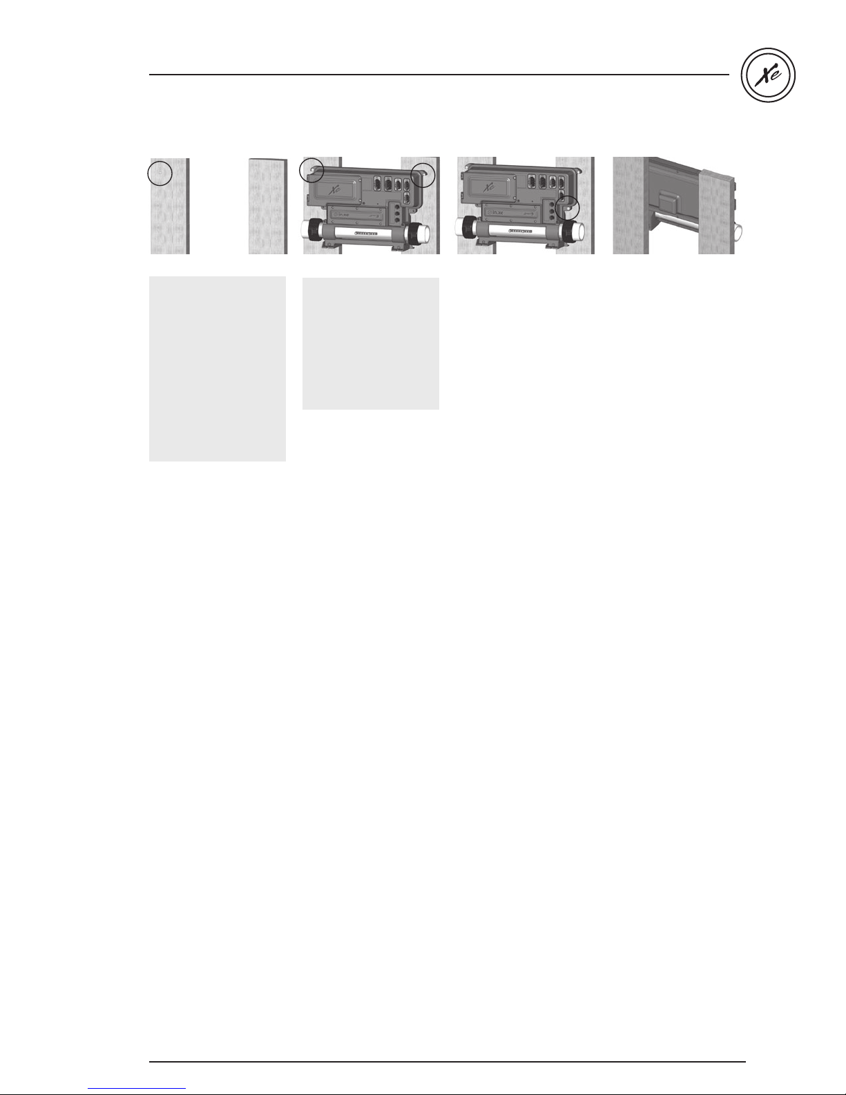
Wall installation procedure
The following material is
recommended:
4- # 10 screws of
appropriate length with
round, truss or pan
head.
4- washers .5" OD x
.0625” thickness (12 mm
OD x
1.5 mm)
Use two 2 standard 2x4
or 2x6 wall studs, spaced
on 16-inch centers to affix
the spa pack.
In the case of a flat
wooden surface: select
the most appropriate
location on wall for
the spa pack. A 4" (52
mm) square cut-out will
be needed to allow
the transformer to fit
through it.
Firmly attach, one at a
time, upper mounting
holes on each side of the
spa pack with 2 screws
backed by 2 washers.
Firmly attach lower
mounting holes on each
side of the pack with
the 2 remaining screws
and 2 washers.
Note: Make sure these
2 screws and 2 washers
are installed. They will
make the pack stable
when input, outputs and
accessory connectors will
be inserted in their ports.
7
Page 9
in.xe TechBook
in.k200 installation & connections
Installing the in.k200
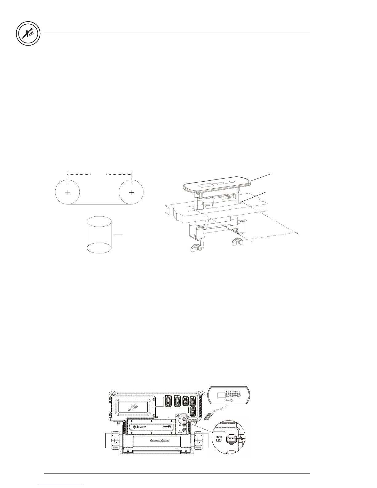
The keypad should be installed directly onto the spa (or very close to it) so that it is easily accessible to the user.
• To install the in.k200, drill two 1” (25 mm) diameter holes at 2.625” (67 mm) from center to center as illustrated.
• Cut out the material between the two holes (see illustration).
• Clean the installation surface and peel the adhesive backing from the keypad.
• Insert keypad and align it correctly, then ensure it is properly glued by gently pressing evenly on the entire surface.
If the keypad is equipped with an optional holder plate, remove the two wing nuts from the back of the keypad and
remove the mounting bracket.
Insert the keypad into the opening you have cut out. Put the mounting bracket and the wing nuts back on their
respective bolts and fix the keypad securely in place (see illustration below).
Gasket with adhesive
∅ 1"
(25 mm)
"
625
.
3
92 mm
∅ 1"
(25 mm)
2.625"
67 mm
∅ 1"
(25 mm)
1" (25 mm)
dia. drill
1"
mm)
(25
Note: It is the installer’s responsibility to ensure that no obstructions (cables, piping, etc.) are present below the deck
at the drill hole location.
Note: If the installation location is not perfectly even (e.g. wood surface), make a silicone joint between the
installation surface and the back of the unit to ensure a proper seal around it.
Connecting the main keypad to the in.xe spa pack
The in.k200 comes with a 10' (3.048 m) cable and an in.link connector.
To connect the in.k200, first remove the in.xe cover (6 screws), then insert the in.link connector into the appropriate
keypad connector (as illustrated.) Route the cable through one of the molded strain relief channels on the bottom
right side of the spa pack (as illustrated.) Don’t forget to replace the cover and all 6 screws (do not over tighten
cover screws.)
Note: always shut power down before connecting an accessory to the in.xe.
8
in.k200
Connect the main keypad
in.k200 as indicated here.
Page 10
in.xe TechBook
in.xe connections
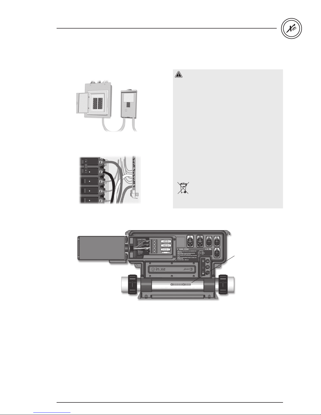
Electrical wiring for North American model of the in.xe
Warning!
For units for use in other than single-family
dwellings, a clearly labeled emergency switch shall
be provided as part of the installation. The switch
shall be readily accessible to the occupants and
shall be installed at least 5' (1.52 m) away, adjacent
to, and within sight of the unit.
-----
This product must always be connected to a circuit
Main electrical box GFCI panel
protected by a ground fault interrupter.
Proper wiring of the electrical service box, GFCI
and in.xe terminal block is essential!
Check your electrical code for local regulations.
Only copper wire should be used, never
aluminum.
-----
Disposal of the product
The appliance (or the product) must be
disposed of separately in accordance with
the local waste disposal legislation in force.
Electrical wiring for North American or CE model of the in.xe
To install the wiring for the in.xe spa control, you'll need
a Phillips screwdriver and a flat screwdriver.
Loosen the 2 screws of the spa pack door and open it.
Remove 5.5" (142 mm) of cable insulation.
Strip away 1" (25 mm) of each wire insulation.
Pull the cable through the cutout of the box
and secure it with a strain relief (1" NPT strain relief;
hole diameter: 1.335").
(For CE use an IEC certified plastic bushing that will
maintain the IPX5 rating.)
Make sure that only the uncut sheathing is clamped
at this opening.
Push the color-coded wires into the terminals as
indicated on the sticker and use the flat screwdriver
to tighten the screws on the terminals.
After making sure wire connections are secure, push
them back into the box and close the door. Tighten
the 2 screws of the spa pack door.
Connect the bonding conductor to the bonding lug on
the front of the in.xe spa pack (a grounded electrode
conductor shall be used to connect the equipment
grounding conductors).
bonding lug
9
Page 11
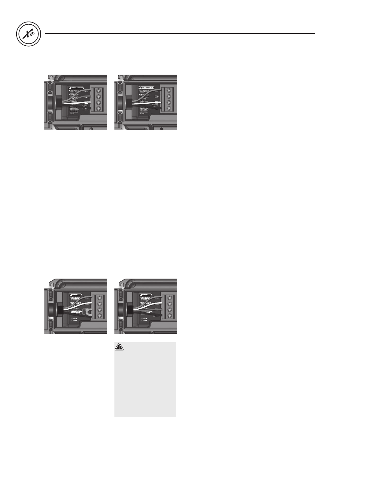
Electrical wiring North American model in.xe
in.xe TechBook
For 240 V (4 wires)
Correct wiring of the
electrical service box,
GFCI, and pack terminal
block is essential.
Call an electrician
if necessary.
For 120 V (*3 wires)
*If connected to a 3
wire system, no 240 V
component will work.
Refer to "Connections
for 120 V heater" section
of this manual.
Electrical wiring European model in.xe.ce
Single-phase Dual-phase
in.xe.ce 230 V
or 230/400 V
Correct wiring of the
electrical service box,
RCD, and pack terminal
block is essential!
Call an electrician
if necessary.
10
Warning!
in.xe.ce models must
always be connected
to a circuit protected
by a Residual-Current
Device (RCD) having
a rated operating
residual-current not
exceeding 30 mA.
Page 12
in.xe TechBook
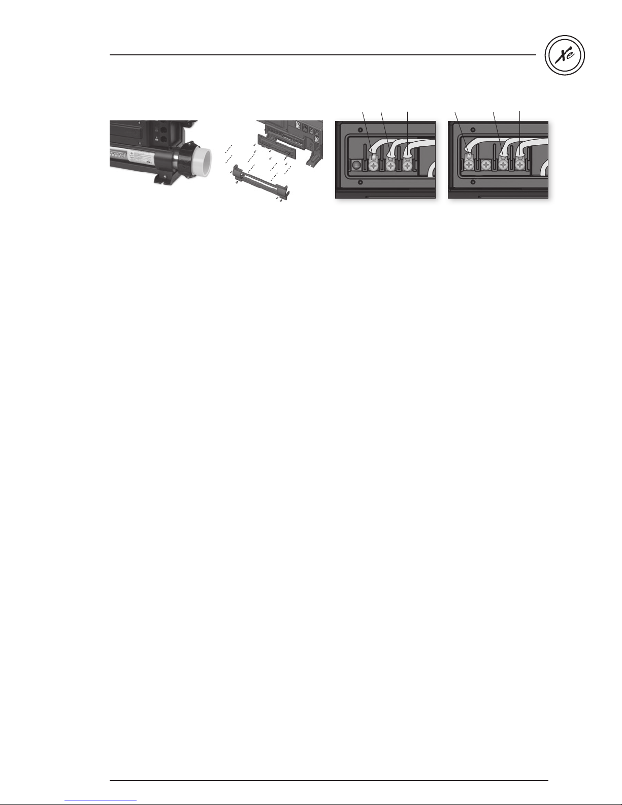
Heater connections
heat.wav heater
in.xe comes with a high performance heat.wav heater.
With no pressure switch, it features in.flo integrated
dry-fire protection.
A watertight panel protects the heater and probe
connectors. Removing the panel gives access to in.flo
dry-fire protection and hi-limit/regulation probe
connectors, line 1, line 2 and ground power input cables
connection ports.
L2 GroundL1
Connections for 230/240 V
heater (4 kW or 2 kW)
Connections for 120 V
heater (1 kW)
GroundN L1
The heat.wav heater is factory configured 240 V /4 kW
(or 2 kW), but it can be converted to a dedicated
120 V / 1 kW by simply switching a cable connection
port. Option available on North American models only.
heat.wav specification summary:
• Supports 120 V or 240 V
• Protected by external breaker (not fused)*
• Incoloy® or Titanium (optional) heater element
for greater protection against corrosion.
*Note: European models are 230 or 240 V and are fuse protected
11
Page 13
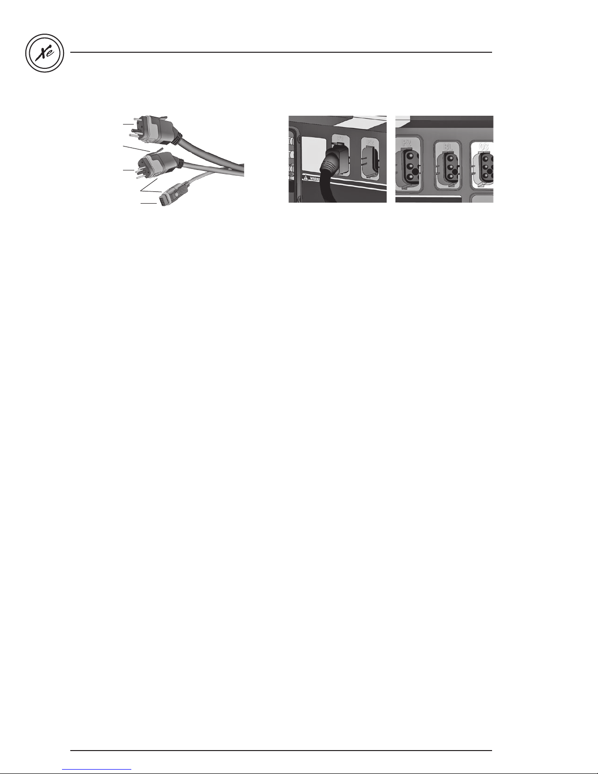
High Current
Integrated latch
Low Current
Colored & tagged
polarizers
Low voltage
in.xe TechBook
in.link connectors
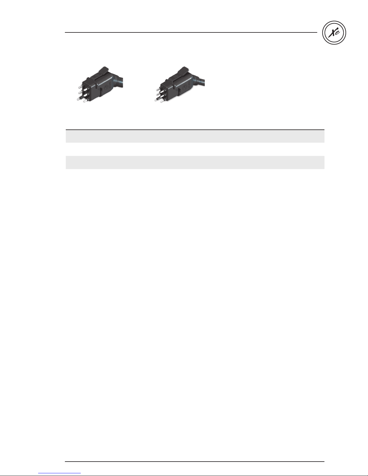
The in.xe features in.link connectors with colored
and tagged polarizers. This new plug and connector
technology has been specifically designed for easy and
safe assembly. The tags are interchangeable depending
on the output; the polarizers are designed to avoid
misconnections.
In.link connectors are easily and conveniently accessible
from the front of the pack offering a wide range of
possible connection configurations. In.link connectors
come in 3 sizes (HC, LC and low voltage) for all types of
inputs and output devices.
Latch snap & strain
relief
A latch mechanism is
provided to maintain male
and female connectors
together. The tab provided
on the male part gives
the operator an audible
and tactile feedback at
the insertion of the cable
in the female part. Once
the latch is engaged, it will
prevent both parts from
separating unintentionally
by vibration or shock.
To unplug the male
connector, a gentle press
on the tab will allow the
release of the locking
mecha-nism to separate
both parts.
Watertight design
UL & CE
The female connector
comes with a built-in
seal ensuring a watertight
connection assembly
sealed from moisture and
water ingress. This sealing
is intended to be suitable
for the North American
and European standards
and the demanding
spa environment.
12
Page 14
in.xe TechBook
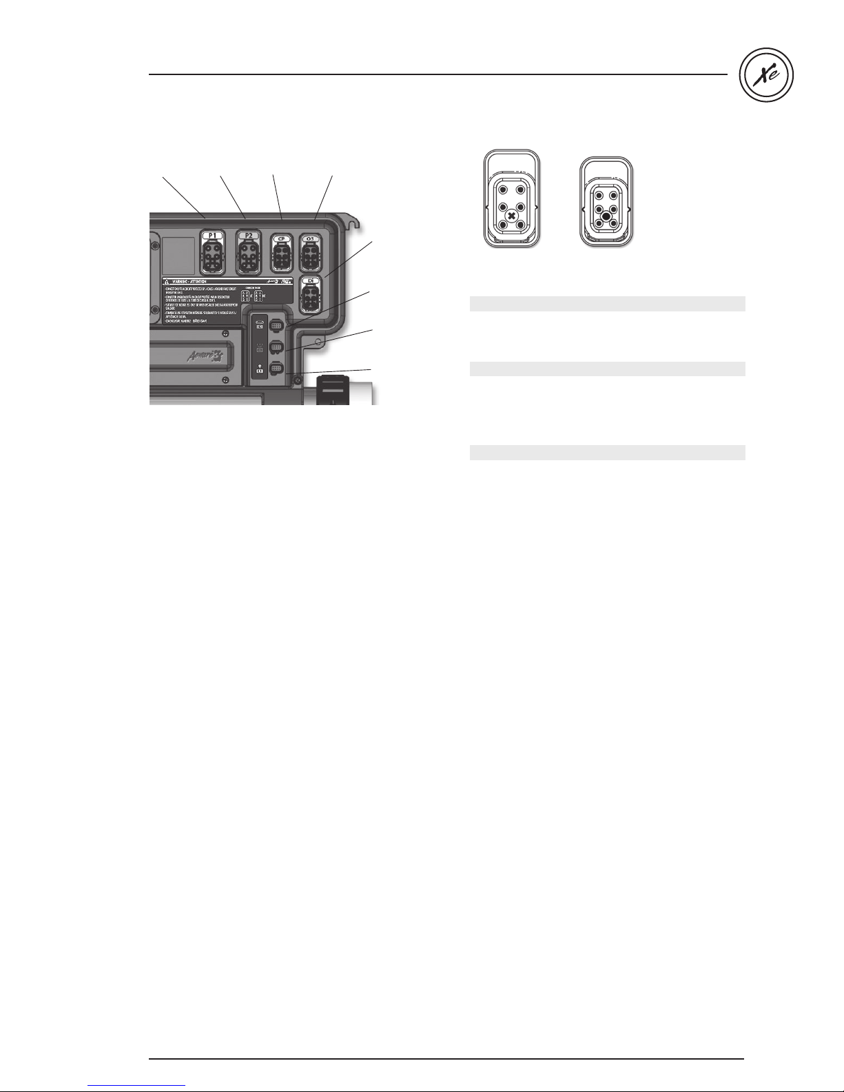
Connector map
Pump 1
connector
* Only available on IN.XE-5. IN.XE-3 has pump 1, ozonator
and direct connectors.
* Pump 2
connector
* Blower
connector
Ozonator
connector
connector
Keypad
connector
Communication
connector
Direct
connector
Light
Female connector on spa pack
3
2
1
6
3
5
2
1
4
6
5
4
LCHC
In.link output connectors:
High-Current - HC connectors:
Output Typical Device
Out 1 Pump 1
Out 2 Pump 2*
Low-Current - LC connectors (relay controlled):
Output Typical Device
Out 3 Blower*
Out 4 Ozonator
Out 5 Audio/video (direct to line)
Low-Voltage - LV connectors:
Output Typical Device
C Main keypad
CO Comm. Connector (in.stik, in.watch)
L1 Light
13
Page 15
in.xe TechBook
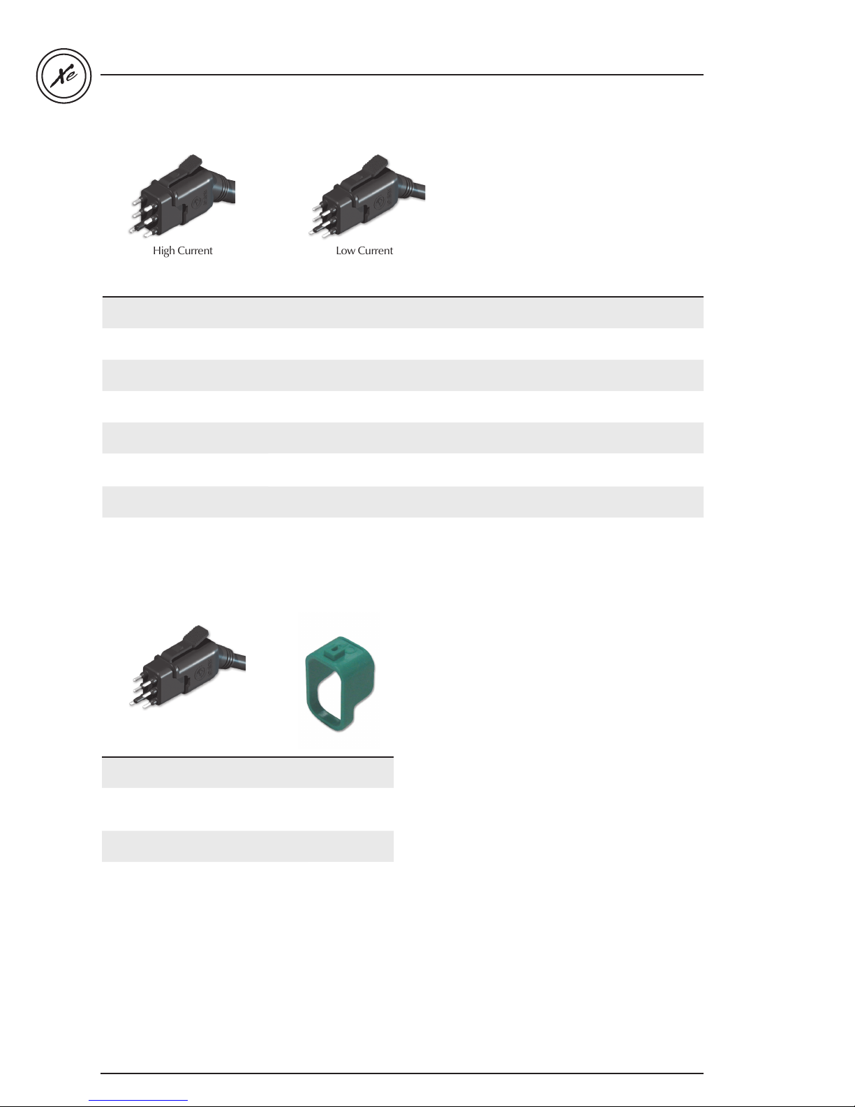
Assembly 240 V cable kit in.link for in.xe
High Current Low Current
Gecko P/N Description Typical use Cable Length
600DB0821
600DB0967
600DB0833
600DB0901
600DB0721
600DB1259
600DB0754
9920-401022
Cable in.link HC 2S
15A 240 V 8'
Cable in.link HC 2S
15A 240 V 8' T CE
Cable in.link HC 1S
15A 240 V 8'
Cable in.link HC 1S
15A 240 V 8' T CE
Cable in.link LC 1S
5A 240 V 4'
Cable in.link LC 1S
5A 240 V 8' T CE
Cable in.link LC 1S
5A 120 V 4'
Cable in.link LV
Light 12 V AC 12'
dual-output loads up to 15 FLA (pump dual speed) 14/4 96"
dual-output loads up to 15 FLA (pump dual speed) for Europe 14/4 96"
single-output loads up to 15 FLA (pump single speed) 14/3 96"
single-output loads up to 15 FLA (pump single speed) for Europe 14/3 96"
single output loads up to 5 FLA (ozone, blower, circ. pump, DC supply, etc.)
single output loads up to 5 FLA (ozone, blower, circ. pump, DC supply, etc.)
for Europe
single output loads up to 5 FLA (ozone, circ. pump, DC supply, etc.) 18/3 48"
light 12 V AC 24/4 144"
18/3 48"
18/3 96"
Assembly 120 and 240 V cable kit in.link for in.xe
Gecko P/N Description Typical use
9917-100894 Keying cable LC - BL - blue
9917-100898 Keying cable LC - O3 - gray
9917-100887 Keying cable HC - P2 - violet
9917-100888 Keying cable HC - P1 - orange
LC Keying
for Blower cable
LC Keying
for Ozonator
cable
HC Keying
for Pump 2 cable
HC Keying
for Pump 1 cable
14
Page 16
in.xe TechBook
Assembly 120 V cable kit in.link for in.xe (continuation)
High Current Low Current
Gecko P/N Description Typical use Cable Length
9920-401239
600DB0857
600DB0754
9920-401022
Cable in.link HC 2S
15A 120 V 8'
Cable in.link HC 1S
15A 120 V 8'
Cable in.link LC 1S
5A 120 V 4'
Cable in.link LV
Light 12 V AC 12'
dual-output loads up to 15 FLA (pump dual speed) 14/4 96"
single-output loads up to 15 FLA (pump single speed) 14/3 96"
single output loads up to 5 FLA (ozone, circ. pump, DC supply, etc.) 18/3 48"
light 12 V AC 24/4 144"
15
Page 17
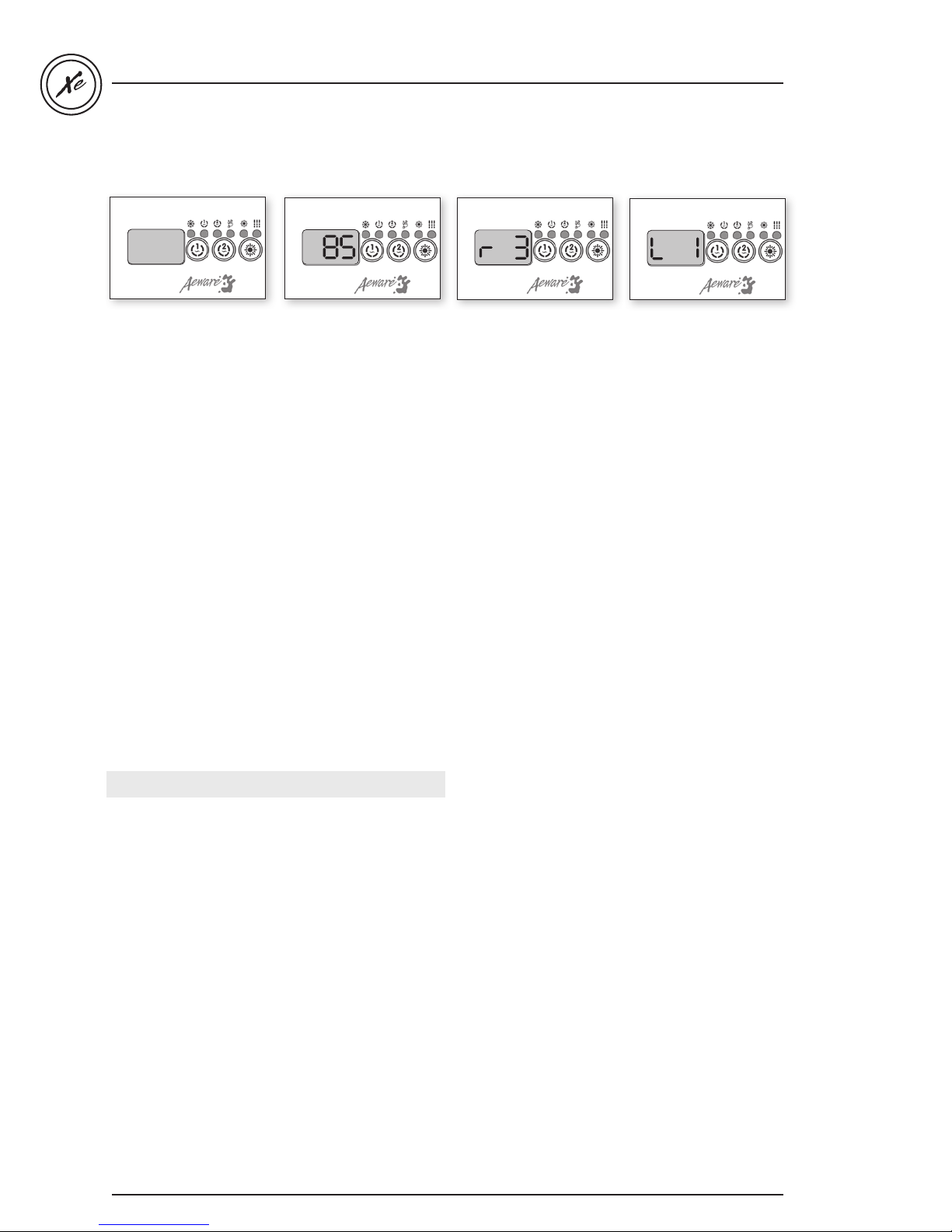
Boot up display sequence (Each parameter is displayed for 2 seconds)
8.8.8
in.xe TechBook
Lamp test
All the segments and LEDs
are lighting up
Software number
Software part number
Valuable Tips
Make sure that all valves are open in the spa plumbing
and that you have good water flow circulating from the
primary pump into the heater.
Important: a minimum flow rate of 18 GPM is required.
Software revision
Revision of the software
Low level selection
Low level selected from
low level menu
Technical information
There is no mechanical switch in the in.xe heater. Instead
in.xe systems have integrated in.flo technology. The in.flo
is an all electronic dry-fire protection device built-in
in.xe's heater.
At power up, in.flo performs a flow check through
the following process:
Pump 1 starts for 2 minutes The display will show "_ _ "
during the check flow process. After 2 minutes the system
validates proper water flow.
16
In case of failure, the system tries again.
The water temperature is shown on the keypad display.
Once the water has reached the set point value plus
0.8 ˚F the heater is turned off.
Page 18
in.xe TechBook
98
Make sure all accessories
are linked to the bonding
connector and connected
to pack.
Turn on the breaker.
It's important to specify
the current rating of the
GFCI used to ensure
safe and efficient current
management (and no
GFCI trippings).
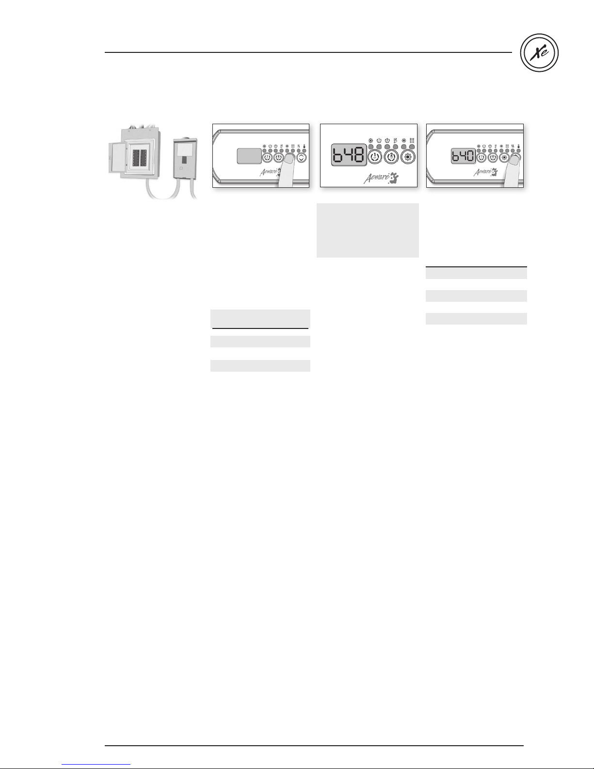
Press and hold Light
button until you access
the breaker setting menu.
Number of Phase
selection
UL Menu not available
CE 1 or 2
UL Swim 1 or 2
CE Swim 1, 2 or 3
The values displayed by
the system correspond
to 0.8 of the maximum
amperage capacity of the
GFCI.
Use the Up/Down button
to select the desired value.
The value can typically be
modified from 10 to 48 for
UL version, and 10 to 40 A
for CE version.
Then press Light button to
set breaker rating.
This table shows typical
settings of Br for GFCI.
Select the one that
matches your breaker.
GFCI Br
60 A 48 A
50 A 40 A
40 A 32 A
30 A 24 A
20 A 16 A
Note: Every OEM has its own
preset configurations.
17
Page 19
Programming the in.xe
using the in.stik
in.xe TechBook
This feature is very useful
on production lines to
configure packs and in the
field for service purposes,
like software updates.
Follow these simple
steps to upload new
predetermined low level
program configurations
into the spa pack.
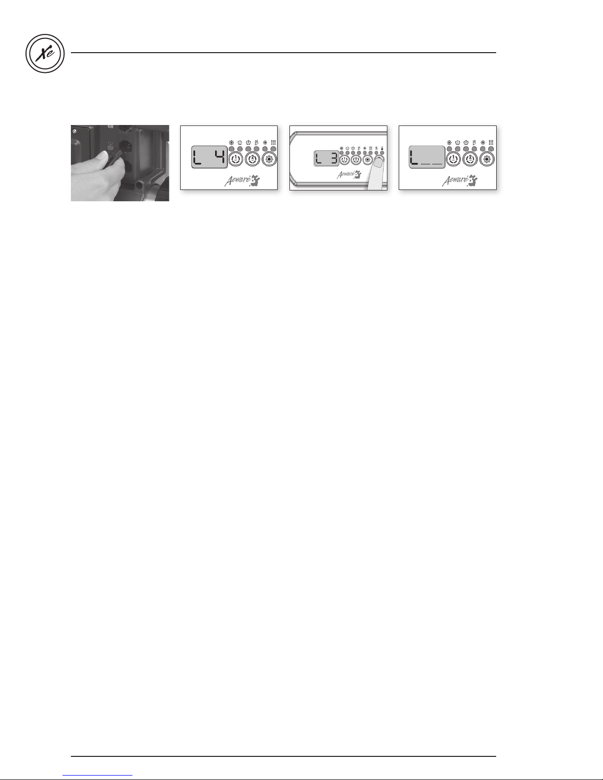
Insert the in.stik in
the communication
connector (see fig. above).
Shut electrical power off.
Turn power on.
At power-up the in.xe
system will upload all the
different configurations set
into the in.stik memory.
The in.xe will then
enter the low-level
configuration menu.
The keypad display will
show L xx where "xx"
represents the previous
configuration number
registered in the system.
Use the Up/Down key
to choose the new
desired low level
configuration number.
Press the Prog. key to
confirm the selected
configuration (consult
the configuration
selection chart section in
this manual).
If the Prog. key is not
pressed within 25
seconds, the unit will
exit this menu without
changing any settings.
Note: If the keypad in use
does not have the Prog.
key, use Light key instead.
If at power-up of the
system your keypad
display shows
the following message:
"L _ _
", it means that all
low level configurations
have been downloaded,
but no configuration
number has been chosen.
18
Page 20
in.xe TechBook
98
Programming the in.xe
using the keypad
Although every in.xe
spa pack is factory set,
in certain cases when
servicing or replacing a
new unit in the field, it
may be necessary to set
a new predetermined
low level program
configuration into
the spa pack.
Follow these simple steps
to re-enter the low level
programming menu using
the keypad:
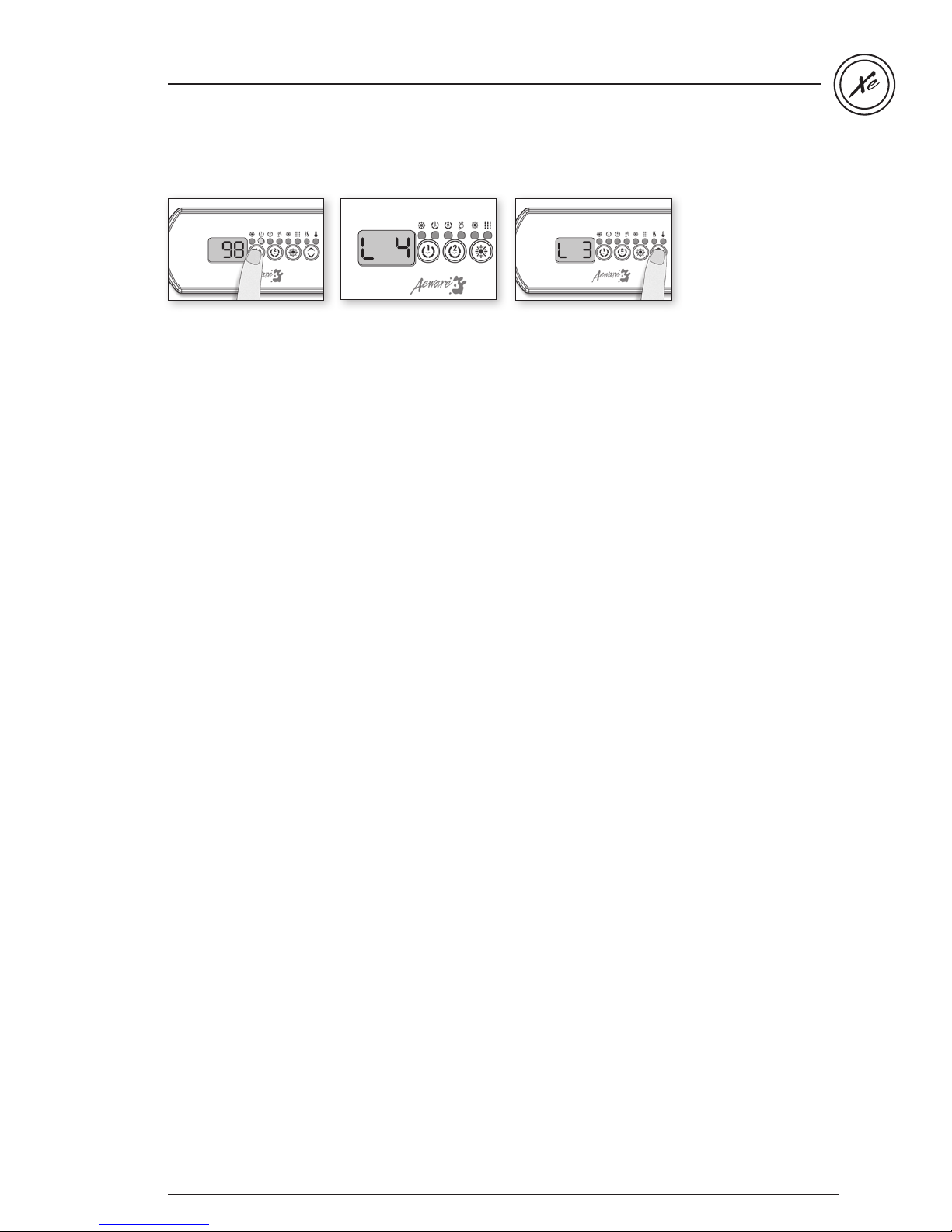
Press and hold the Pump 1
key for 30 seconds.
The keypad display will
show L xx where "xx"
represents the previous
configuration number
registered in the system.
Use the Up/Down key to
choose the new desired
low level configuration
number and press the
Program key to confirm
the selected configuration
(consult the configuration
selection chart section in
this manual).
If the Program key is
not pressed within 25
seconds, the unit will
exit this menu without
changing any settings.
If at power-up of the
system your keypad
display shows the
following message:
"L _ _
", it means that all
low level configurations
have been downloaded,
but no configuration
number has been
chosen.
Note: If the keypad in
use does not have the
Program key, use the
Light key instead.
19
Page 21
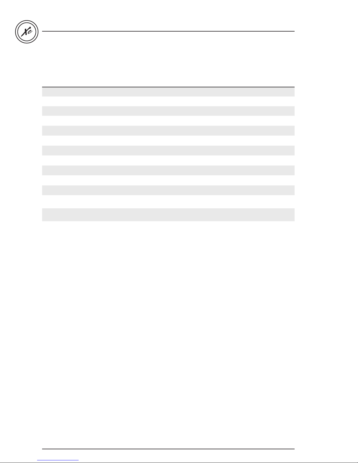
Low Level Configuration Selection Chart
in.xe with low level 85 revision 1, 2 and 3.
in.xe TechBook
Config. # P1
1 2sp 1sp X Always on --- Clean, P1L P1
2 2sp 1sp X Always on --- Purge CP
3 2sp 1sp X --- On during Filter cycle, with P1 Clean, P1L P1
4 2sp 1sp - Duration filtration On during Filter cycle, with CP Clean, CP P1
5 2sp 1sp - Always on Always on with CP Clean, P1L CP
6 2sp 1sp - Duration filtration On during Filter cycle, with CP Clean, CP CP
7 2sp 1sp - --- On during Filter cycle, with P1 Clean, P1L P1
8 2sp - X --- On during Filter cycle, with P1 Clean, P1L P1
9 2sp - - --- On during Filter cycle, with P1 Clean, P1L P1
10 1sp 1sp X --- On during Filter cycle, with P1 Clean, P1L P1
11 1sp 1sp - Duration filtration On during Filter cycle, with CP Clean, CP P1
12 1sp 1sp - Always on Always on with CP Purge CP
13* 1sp Always on Always on with CP Purge CP
BL CP configuration Ozone configuration Filter Type Heater Pump
P2
Note: Every OEM has its own preset configurations.
The ow level configuration may differ depending
on the manufacturer.
* Available on Rev 3.00 only
20
Page 22
in.xe TechBook
in.xe programming field options
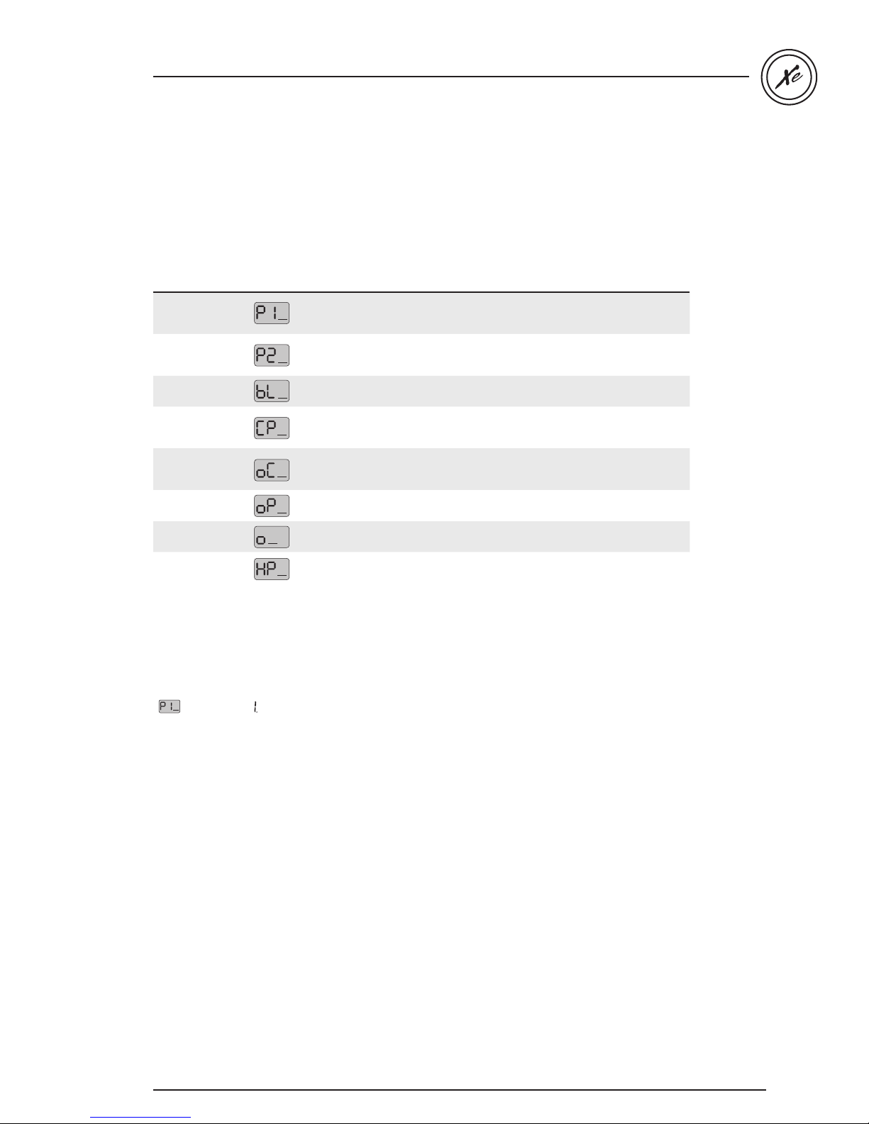
In the event where none of the predetermined low level
program configurations built in the in.xe system suit
your spa equipment assembly, it's possible to custom
To access this menu, press and hold Prog. (or Light key)
for 30 seconds. Use Up/Down key to choose setting.
Press Prog. key (or Light key) to go to the next parameter.
configure the in.xe system by manually entering key
parameter settings.
Table 1
Parameter Display Options Description
Pump 1 Config
Pump 2 Config
Blower Config
Circ. Pump Config
Ozone Config
Ozone Pump
Ozone Type
Heater Pump
Single-speed = 1
Dual-speed = 2
*Pump #1 and Pump #3 = 3
Not installed = 0
Single-speed = 1
Dual-speed = 2
Not installed = 0
Installed = 1
Not installed = 0
Installed = 1
Always on = 2
Not installed = 0
During filter cycle = 1
Always on = 2
Circulation pump = 0
Pump #1 = 1
Standard = 0
Timed = 1
Circulation pump = 0
Pump #1 = 1
Pump #1 configuration
*Available only on certain models.
Pump #2 configuration
Blower configuration
Circulation pump configuration
Ozone generator configuration
Pump associated to ozone generator
Type of ozone generator
Pump associated to heater
Please note that there are three versions of field options
available, depending on your software revision.
Tables 1 & 2 were used with previous versions.
Table 3 is the latest version. The first parameter will help
to indicate which table to consult.
( = table 1) and ( = table 2 or 3)
--
21
Page 23
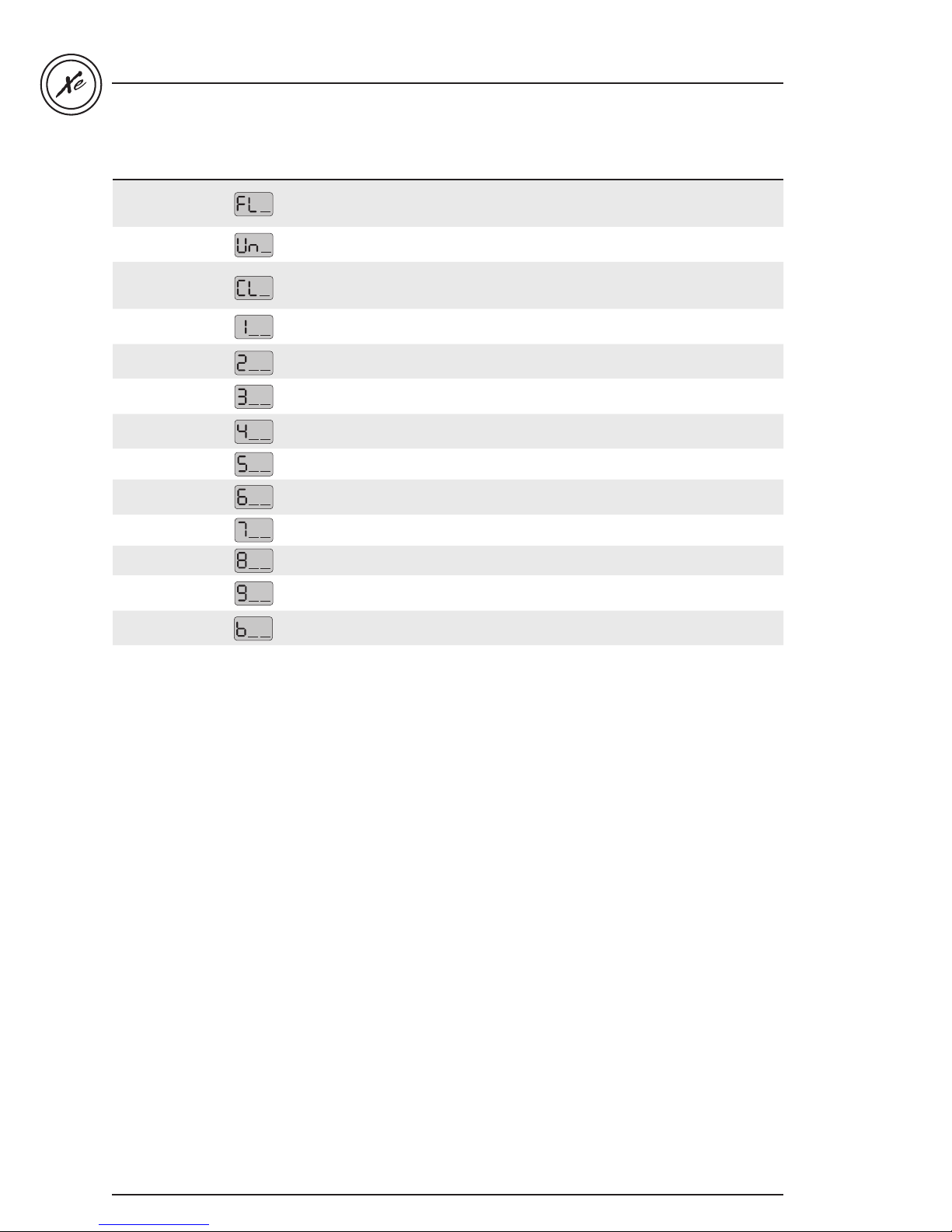
Table 1
Parameter Display Options Description
Filter Config
Temp. Units
Time Format
Pump #1
High current
Pump #1
Low current
Pump #2
High current
Pump #2
Low current
Blower current 1 to 10 amperes (5) Blower current
Circ. Pump current 1 to 5 amperes (2) Circulation pump current
Purge only = 0
With Circ. Pump = 1
With Pump #1, Low speed = 2
°F = 0
°C = 1
No time display = 0
AM/PM format = 1
24H format = 2
1 to 20 amperes (10) Pump #1 high speed current
1 to 15 amperes (4) Pump #1 low speed current
1 to 15 amperes (10) Pump #1 low speed current
1 to 15 amperes (4) Pump #2 low speed current
Filter cycle configuration
Temperature units used on display
Clock display format
in.xe TechBook
Direct current 0 to 5 amperes (1) Direct accessory output current
Heater current 4 to 17 amperes (17) Heater current
Minimum input
current
Input current
10 to 20 amperes
15 to 48 (on UL/CSA packs) (48)
15 to 32 (on CE packs) (32)
Minimum input current
(circuit breaker)
Available household supply current
*Available only on certain models.
22
Page 24
in.xe TechBook
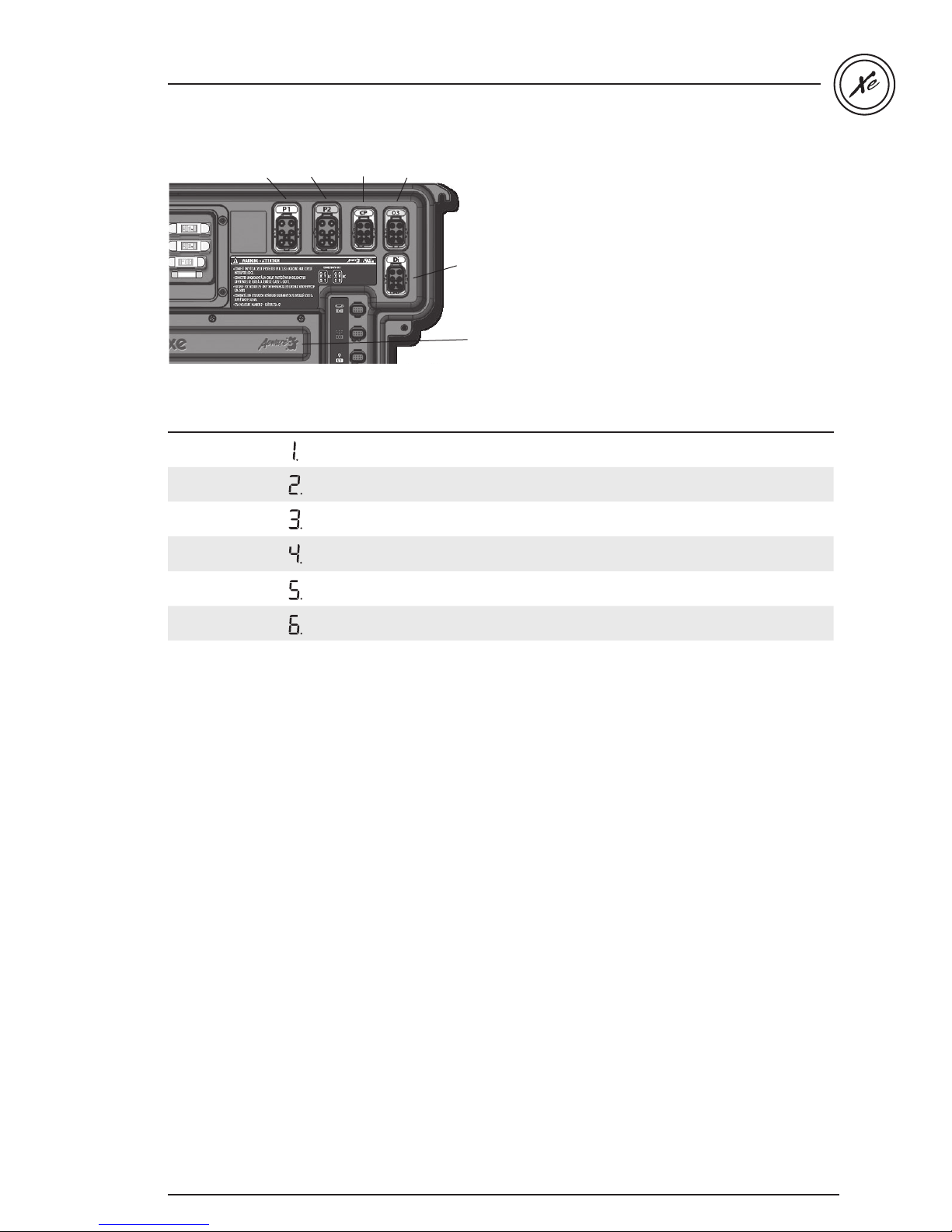
Output 2Output 1 Output 3 Output 4
Direct output
Output 5 or
heater
Table 2
Parameter Display Options Description
Output 1A
--
Output 1B
Output 2
Output 3
Output 4
--
--
--
--
Output 5 --, H Accessory connected to the relay of Output 5A
--,1H,1L,2H,2L,3H,3L,4H,
4L,P5,BL,CP,O3,L2,H
--,1H,1L,2H,2L,3H,3L,4H,
4L,P5,BL,CP,O3,L2,H
--,1H,1L,2H,2L,3H,3L,4H,
4L,P5,BL,CP,O3,L2,H
--,1H,1L,2H,2L,3H,3L,4H,
4L,P5,BL,CP,O3,L2,H
--,1H,1L,2H,2L,3H,3L,4H,
4L,P5,BL,CP,O3,L2,H
Accessory connected to the relay of Output 1A
Accessory connected to the relay of Output 1B
Accessory connected to the relay of Output 2A
Accessory connected to the relay of Output 3A
Accessory connected to the relay of Output 4A
--
23
Page 25
Table 2
Parameter Display Options Description
CP usage
Ozone usage
Ozone Pump
Ozone Type
Heater Pump
Filter Config
Temp. Units
Clock Format
-
-
-
-
-
-
-
-
CP standard = 0
CP always on = 1
Ozone with filtration = 0
Ozone always on = 1
Circulation pump = 0
Pump #1 = 1
Standard (UV) = 0
Timed (Corona) = 1
Circulation pump = 0
Pump #1 = 1
Purge only = 0
With circ. pump = 1
With pump 1, low speed = 2
°F = 0
°C = 1
No time display = 0
AM/PM format = 1
24H format = 2
Usage of the circulation pump
Usage of the ozone generator
Pump associated with the ozone generator
Type of ozone generator
Pump associated with the heater
Filter cycle configuration
Temperature units used on display
Clock display format
in.xe TechBook
Cool down 30 to 240 seconds Cool down of the heating element in seconds
Output 1A current 1 to 20 amperes
Output 1B current 1 to 15 amperes
Output 2 current 1 to 15 amperes
Output 3 current 1 to 15 amperes
Output 4 current 1 to 15 amperes
Output 5 current 1 to 17 amperes
Direct current 0 to 5 amperes Current draw of the Direct output
Minimum input
current
Number of phases 1 or 2 (UL)
Input current 10 to 60 A Single Phase (UL and CE)
--
--
--
--
--
--
--
--
--
--
--
10 to 20
1, 2 or 3 (CE)
10 to 48 A Dual Phase (UL)
10 to 40 A Dual Phase (CE)
10 to 20 A Triple Phase (CE)
Current draw of the accessory connected to
the relay of Output 1A
Current draw of the accessory connected to
the relay of Output 1B
Current draw of the accessory connected to
the relay of Output 2A
Current draw of the accessory connected to
the relay of Output 3A
Current draw of the accessory connected to
the relay of Output 4A
Current draw of the accessory connected to
the relay of Output 5A
Minimum input current (breaker size)
Number of Phase / Breaker
Number of Phases selection
UL Menu not available
CE 1 or 2
UL Swim 1 or 2
CE Swim 1, 2 or 3
Available household current
Maximum Input Current
1 phase 2 Phases 3 Phases
UL 48 na na
CE 40 20 na
UL Swim 60 48 na
CE Swim 60 40 na
24
Page 26
in.xe TechBook
Table 3
Parameter Display Options Description
Output 1A
--
Output 1B
Output 2
Output 3
Output 4
--
--
--
--
Output 5 --, H
--
Output Direct
--
CP usage
-
Ozone usage
-
Ozone Pump
-
Ozone Type
Heater Pump
-
-
Filter Config
Temp. Units
-
-
Clock Format
-
Cool down 30 to 240 seconds
Output 1A current 1 to 20 amperes
Output 1B current 1 to 15 amperes
Output 2 current 1 to 15 amperes
Output 3 current 1 to 15 amperes
Output 4 current 1 to 15 amperes
Output 5 current 1 to 17 amperes
Direct current 0 to 5 amperes Current draw of the Direct output
Minimum input
current
Number of phases
--
--
--
--
--
--
--
--
--
--,1H,1L,2H,2L,3H,3L,4H,
4L,P5,BL,CP,O3,L2,H
--,1H,1L,2H,2L,3H,3L,4H,
4L,P5,BL,CP,O3,L2,H
--,1H,1L,2H,2L,3H,3L,4H,
4L,P5,BL,CP,O3,L2,H
--,1H,1L,2H,2L,3H,3L,4H,
4L,P5,BL,CP,O3,L2,H
--,1H,1L,2H,2L,3H,3L,4H,
4L,P5,BL,CP,O3,L2,H
Direct = -CP on Direct = CP
CP Standard = 0
CP Always On = 1
Ozone with filtration = 0
Ozone Always On = 1
Circulation pump = 0
Pump #1 = 1
Standard (UV) = 0
Timed (Corona) = 1
Circulation pump = 0
Pump #1 = 1
Purge only = 0
With Circ. Pump = 1
With Pump 1, Low speed = 2
°F = 0
°C = 1
No time display = 0
AM/PM format = 1
24H format = 2
10 to 20
1 or 2 (UL)
1, 2 or 3 (CE)
--
Accessory connected to the relay of
Output 1A
Accessory connected to the relay of
Output 1B
Accessory connected to the relay of
Output 2A
Accessory connected to the relay of
Output 3A
Accessory connected to the relay of
Output 4A
Accessory connected to the relay of
Output 5A
Set to CP only if the circulation pump is
connect on the Direct.
Usage of the circulation pump
Usage of the ozone generator
Pump associated with the ozone generator
Type of ozone generator
Pump associated with the heater
Filter cycle configuration
Temperature units used on display
Clock display format
Cool down of the heating element in
seconds
Current draw of the accessory connected
to the relay of Output 1A
Current draw of the accessory connected
to the relay of Output 1B
Current draw of the accessory connected
to the relay of Output 2A
Current draw of the accessory connected
to the relay of Output 3A
Current draw of the accessory connected
to the relay of Output 4A
Current draw of the accessory connected
to the relay of Output 5A
Minimum input current (breaker size)
Number of Phase / Breaker
Number of Phases selection
UL Menu not available
CE 1 or 2
UL Swim 1 or 2
CE Swim 1, 2 or 3
Input current 10 to 60 A Single Phase (UL and CE)
--
10 to 48 A Dual Phase (UL)
10 to 40 A Dual Phase (CE)
10 to 20 A Triple Phase (CE)
Available household current
Maximum Input Current
1 phase 2 Phases 3 Phases
UL 48 na na
CE 40 20 na
UL Swim 60 48 na
CE Swim 60 40 na
25
Page 27

in.xe TechBook
26
Page 28
in.xe TechBook
in.k200 keypad overview
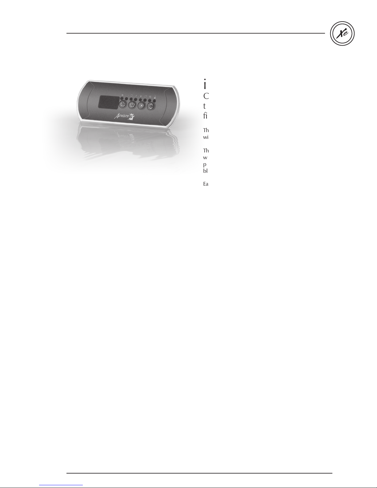
in.k200
Compact series of entry-level keypads
that gives complete control to wet
fingers!
The in.k200 is a compact keypad designed to be used
with Aeware’s in.xe spa system.
This new series of entry-level keypads comes in a
waterproof plastic enclosure and is available in single
pump, dual pump; dual pump/blower, or pump/
blower configurations.
Easy to install, in.k200 comes with an in.link connector.
Note: The following instructions are generic and provide a
quick overview of the main functions. Please refer to your own
QRC for specific functions.
27
Page 29
98
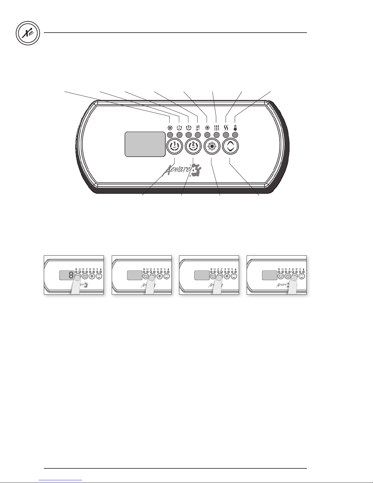
Function description
989898
98
in.xe TechBook
Smart Winter Mode
indicator
Instructions
Pump 1
indicator
Pump 2
indicator
Key 1
Blower
indicator
Light
indicator
Key 2
Filter
indicator
Light key
Heater
indicator
Up/Down key
set point
indicator
Key 1
Key 2 2 Pump
(or single pump/blower)
Press Key 1 to turn Pump
1 on at low speed. Press a
second time to turn pump
to high speed (with a dualspeed pump). A third time
turns pump off.
A built-in timer
automatically turns pump
off after a predetermined
period of time, unless
it has been manually
deactivated.
The Pump 1 indicator
lights up when Pump 1
is on. With dual-speed
pump, the indicator will
flash when Pump 1 is on at
low speed.
28
Press Key 2 to turn pump
2 or blower on. Press a
second time to turn pump
or blower off.
A built-in timer
automatically turns pump
off after a predetermined
period of time, unless
it has been manually
deactivated.
The Pump 2 and/or Blower
indicator lights up when
the corresponding output
is on.
Note: with dual-speed
pump, the indicator will
flash when pump 2 is on at
low speed.
Key 2
(2 Pump/Blower)
Press
Key 2 to turn pump
2 on at high speed.
Pressing a second time
turns blower on. A third
press turns pump 2 off but
leaves blower on. A final
press turns blower off.
A built-in timer
automatically turns
pump/blower off after a
predetermined period of
time, unless it has been
manually deactivated.
The Pump 2 and/or Blower
indicator lights up when
the corresponding output
is on.
Light key
Press
Light key to turn light
on. Press Light key a second
time to turn light off.
A built-in timer
automatically turns light
off after a predetermined
period of time, unless it has
been manually deactivated.
The Light indicator lights
up when light is on.
Page 30
in.xe TechBook
98
F 2
F 2
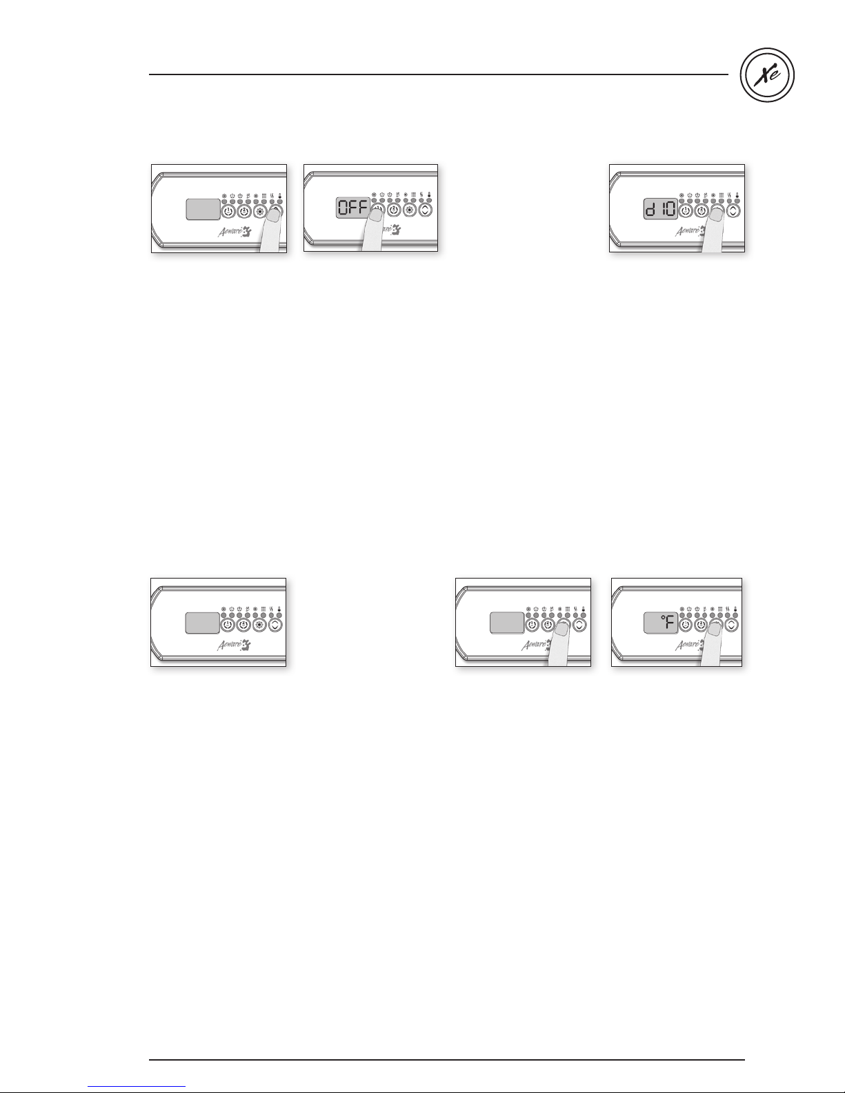
Up/Down key
Use
Up or Down key to set
desired water temperature.
The temperature setting
will be displayed for 5
seconds to confirm your
new selection.
The Set Point icon indicates
that the display shows
the desired temperature,
NOT the current water
temperature!
Off Mode
This mode allows you
to stop all outputs for
30 minutes to perform a
quick spa maintenance.
Press and hold
seconds to activate the off
mode. Quick press
to reactivate the system
before the expiration of
the 30 minute delay.
While the off mode is
engaged, the display will
toggle between
the water temperature.
Key 1 for 5
Key 1
OFF and
Programming the system
Depending on system
configuration the system
performs either filter cycles
or purge cycles.
Programming filter cycles
To program the filter cycles,
you must enter these
parameters: duration and
frequency. During a filter
cycle, pumps & blower
run at high speed for
one minute to purge the
plumbing. Pump 1 or CP
then runs at low speed for
the remainder of
the cycle.
Setting filter cycle duration
Press and hold
Light key until the display
shows
representing the duration
in hours.
Use Up or Down key to
change setting.
0 = no filtration
24 = continuous filtration
Note:
it's not recommended to
set this to "0".
Prog or
dxx, with "xx"
Filter cycle frequency
Press Prog or Light
key again. The display
will show
representing the number
of filter cycles
per day (up to 4).
Use Up or Down key to
change setting.
When the desired
setting is displayed, press
Light key to confirm.
A filter cycle will start
immediately.
The Filter indicator lights
up when a filter cycle is on.
Fx, with "x"
Programming purge
cycles
To program the purge
cycles, you must select
the frequency. During a
purge cycle, all pumps
and the blower run for
one minute.
Purge cycle frequency
Press and hold Light key
until the display shows Fx,
with "x" representing the
number of purge cycles
per day (up to 4).
Use
Up or Down key to
change setting.
When the desired
setting is displayed, press
Light key to confirm.
A purge cycle will start
immediately.
The Filter indicator lights
up when a purge cycle
is on.
Setting the temperature
display units
Quick press Light key
again.
The display will show
either
°F or °C.
Use
Up or Down key to
change units.
Press
Light key a last time
to go back to normal
mode.
°F = Fahrenheit
°C = Celsius
29
Page 31
in.xe TechBook
Water temperature
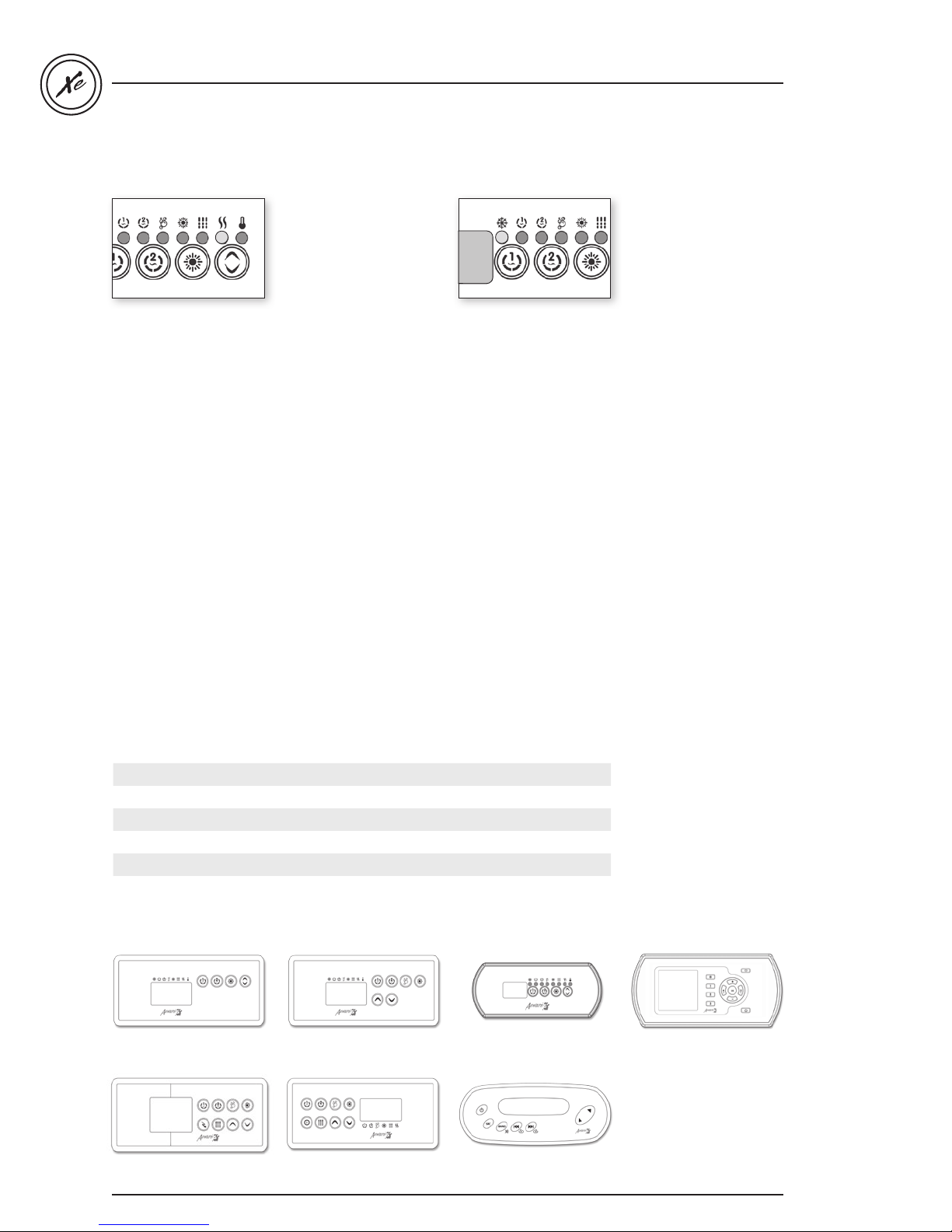
Smart Winter Mode
regulation
In a regulation cycle,
the system first generates
water flow through the
heater housing and the
plumbing, in order to
ensure accurate water
temperature readings as
well as avoiding heater
activation in dry
conditions.
If the readings received
from the system are not
valid, blanks (- - -) will be
displayed until normal
readings have been
successfully found.
After verifying pump
activation and taking
a water temperature
Our Smart Winter Mode
protects your system
from the cold by turning
pumps on several times a
day to prevent water from
freezing in pipes.
The Smart Winter Mode
indicator lights up when
the Smart Winter Mode
is on.
reading if required, the
The system verifies
periodically that all
parameters are within
normal range.
system automatically
turns the heater on to
reach and maintain water
temperature at set point.
The Heater indicator lights
up when the heater is on.
It flashes when there is
a request for more heat
but the heater has not yet
started.
Typical settings
Adjustable Regulating set point: 59°F (15°C) to 104°F (40°C)
Factory Default set point: Typical 95°F (35°C) / Max 100°F (38°C)
Filter Cycle Duration: 0 to 24 hrs / Factory set at 2hrs
Filter Cycle Frequency: 1 to 4 times a day / Factory set at 2
Filter Cycle Start: 00:00 to 23:59 / Factory set at 12:00
Pump Runtime: 1 to 255 min. / Factory set at 20 min.
Light Timeout: 1 to 255 min. / Factory set at 120 min.
Cool down
After heating the spa water
to the desired set point,
the heater is turned off,
but its associated pump
(pump 1 low-speed or CP)
remains on for a certain
amount of time to ensure
adequate cooling of the
heating element,
prolonging its life.
The Heater icon flashes
during this time.
Keypads available for the in.xe:
in.k4
30
in.k8
in.k200 (LED display, 4 keys,
8 light indicators)
in.k450 (LCD display,
6 keys, 10 function icons)
in.k600 (streamlined)in.k19 in.k35
Page 32
in.xe TechBook
in.xe error codes
in.xe error codes summary
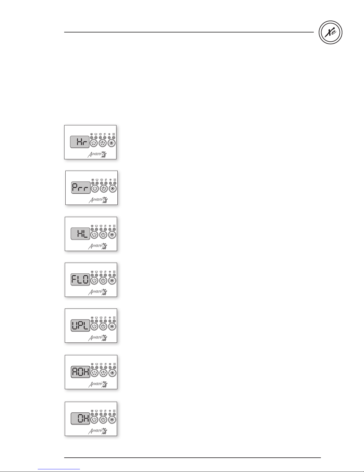
Error codes indicate a failure condition or a problem which needs to be corrected to ensure proper functioning
of the system. Both the error code and the water temperature are alternatively displayed.
All errors codes will be displayed on the keypad display.
Hr
An internal hardware error has been detected in the in.xe.
Prr
The Prr error message indicates a problem with the
regulation probe. The system is constantly verifying if
temperature probe reading is within normal limits.
HL
Water temperature at the heater has reached 119°F.
Do not enter spa water!
FLO
The system did not detect any water flow while the main
pump was running.
UPL
No low-level configuration software has been
downloaded into the system.
AOH
Temperature inside the spa skirt is too high, causing
the internal temperature in the in.xe to go above
normal limits.
OH
Water temperature in the spa has reached 108°F.
Do not enter spa water!
Specifications subjet to change without prior notice.
31
Page 33
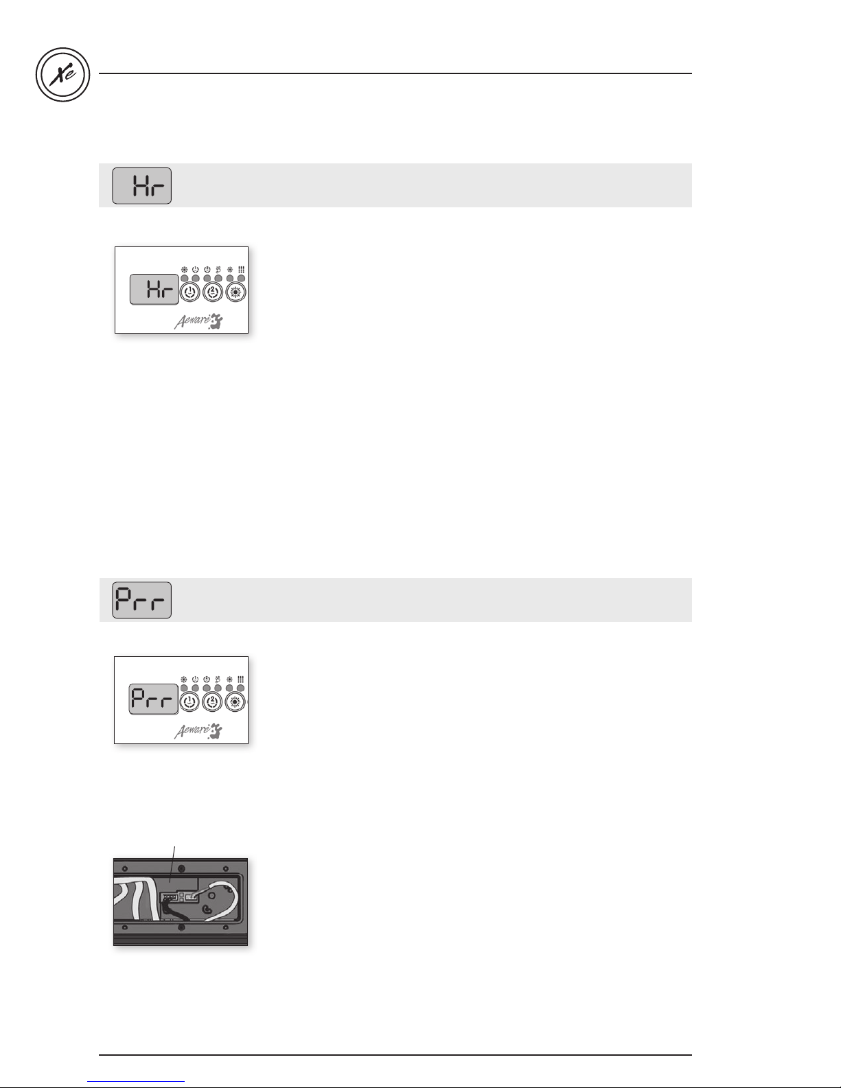
Hr error message / step-by-step
An internal hardware error has been detected
Step-by-Step
• Restart the spa pack
and start & stop all
pumps and blower.
• If error reappears,
replace the in.xe
spa pack.
in.xe TechBook
Prr error message / step-by-step
Regulation probe issue
Step-by-Step
• Verify if regulation
probe (located above
the heater) is properly
connected.
HL Probe & Temp / Regulation Probe
• Replace heater
if problem persists.
• Replace spa pack,
if problem persists.
32
32
Page 34
in.xe TechBook
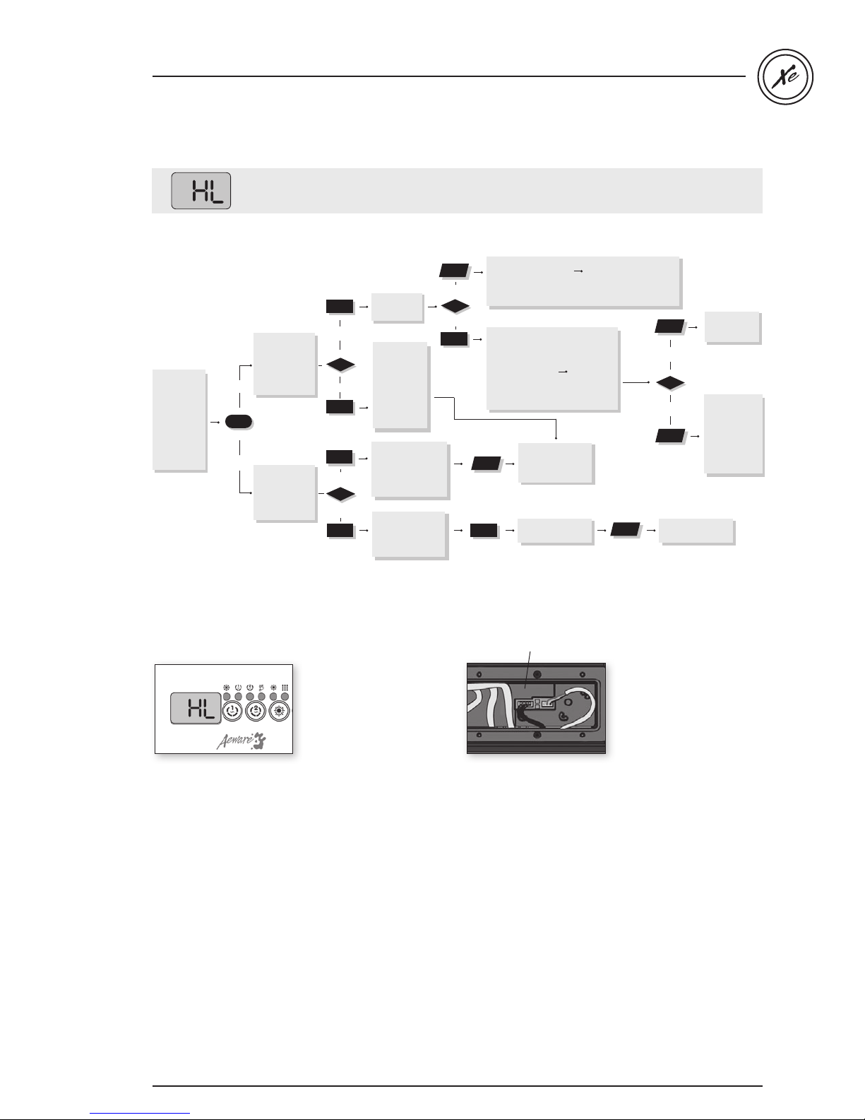
HL error message / flow chart & step-by-step
The system has shut down because the temperature at the heater has reached
119°F (48°C).
Flow chart
Take water
e
temperatur
a digital
with
thermometer.
Is water
temp.
119°F or
higher?
* To Reset System:
Turn power off
and on again at
eaker
the main br
arning!
** W
Handle with care as
heater may be r
Step-by-Step
eally
.
yes
no
hot!
Are you getting
correct water
temperature
reading on
the display?
When HL error
curs,
message oc
does heater
barrel feel
hot? **
Remove spa cover
(even
during the night)
t
blower, if spa is
Star
yes
no
equipped with one.
Lower set point
below actual water
temperature.
Heater indicator
on
keypad display
should
disappear.
If HL error
message persists,
eplace
r
If problem persists,
replace
Is the
weather
very hot?
yes
Verify if
temperature
probe is
no
properly
connected.
If so, r
heater.
Reset
Verify if anything
is
flow (closed tr
or dirty filters).
Reset
Verify if Hi-Limit
probe is pr
connected.
Reset system.*
no
yes
eplace
system.*
obstructing water
aps
system.*
operly
spa pack.
ater
he
Do you get
a 240 V
reading
between
the two
heater
wires on the
board?
.
Wait until spa cools
down (add cold water
if needed).
Reset system.*
Replace
spa
yes
no
If problem persists,
replace
Pump
overhe
water
filter
Lower filter
cycle
Reset system.*
spa pack.
pack.
is
ating
during
cycle.
duration.
HL Probe & Temp / Regulation Probe
HL
Water temperature at the
heater has reached 119°F
1 Measure the tempe-
rature with a DIGITAL
thermometer and
compare its reading
with temp. on the
display. Make sure the
temp. reading is lower
than 119°F.
2 If reading is below 119°F:
• Carefully check if
heater barrel feels hot.
If it’s hot, verify if
anything is obstructing
water flow (closed
valves or dirty filter).
• Shut power off and
power the spa up
again to reset the
system.
• If HL error persists,
replace heater.
• If HL error persists,
replace spa pack.
3 If reading is 119°F or
higher:
• Verify if the Temp &
High Limit probes are
properly connected.
• Shut power off and
power the spa up
again to reset the
system.
• If problem persists,
replace heater.
• If problem persists,
replace spa pack.
3333
Page 35
in.xe TechBook
L2 GroundL1N
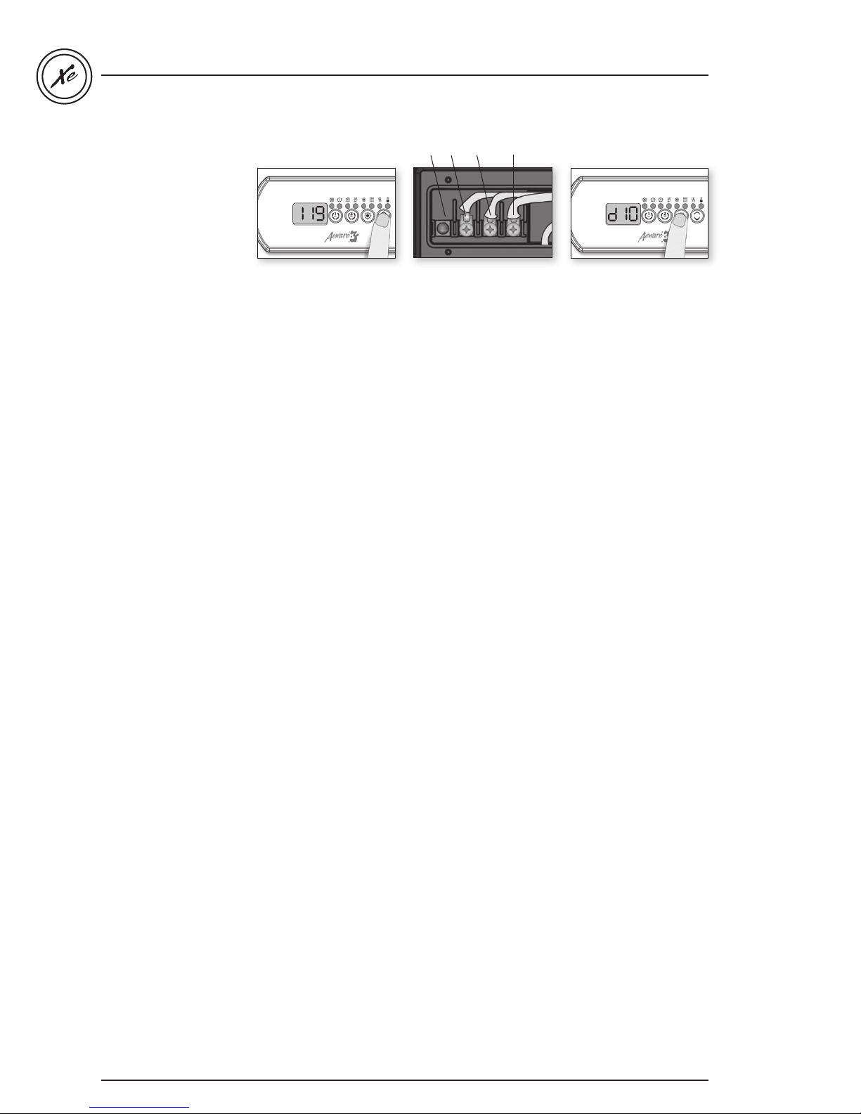
If weather is very hot:
1• Remove spa cover
(even during the night).
Start blower if spa is
equipped with one.
Wait until spa cools
down (add cold water
if necessary).
• Shut power off and
power the spa up again
to reset the system.
If hot weather is not
a factor:
2• Lower set point
below current water
temperature.
The Heater indicator
should disappear from
keypad display.
3• With a voltmeter, read
voltage between the
live and ground heater
terminals.
4• If you do read 240 V,
replace spa pack.
5• If you do not read
240 V, pump may be
overheating water
during filter cycle.
Shorten filter
cycle duration.
To shorten filter cycle
duration:
6• Press and hold the
Light key for 5 seconds.
Display will show a
value that represents
the filter cycle duration
in hours.
7• Use the Down arrow
key to lower the
number of hours.
0 = no filtration
12 = continuous filtration
When the desired
setting is displayed,
press Light key again.
The filter cycle will start
immediately.
34
Page 36
in.xe TechBook
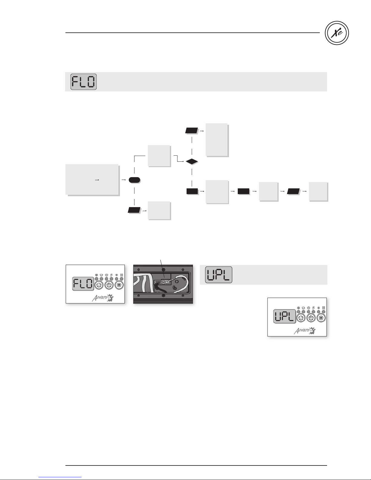
FLO & UPL error message / flow chart & step-by-step
The system did not detect any water flow while the primary pump was running.
Follow the troubleshooting flow chart below to identify the problem:
Make sure that the low-level programming has been properly set, with or without circulation pump
(depending on your system configuration).
Flow chart
There must be
adequate water in
spa for normal use
(a minimum of
18
GPM must
circulate thr
ough
ater)
the he
Step-by-Step
Is pump
working
when you
try to start
it from
keypad?
Remove
anything
obstructing
filter. Clear
Is anything
limiting the
flow of water
into the
pipes?
yes
no
Refer to
“Pump not
Working”
section.
yes
no
any air locks
and verify
water valves.
Verify if
.flo cable
in
operly
is pr
connected
If problem
persists,
replace
heater
If problem
persists,
replace
spa pack
in.flo cable
No low-level configuration software
in system!
Step-by-Step
FLO
Primary pump is activated,
but the system doesn't
detect any water flow
• Make sure water valves
are open and that water
level is high enough.
• Check and remove
anything obstructing the
filter.
• Make sure there are
no air locks (or that no
object obstructs the
passage of water in
the heater channel).
Pumps may make
strange noises.
Follow air lock procedure
to clear them.
• Make sure that the
pump associated to the
heater (primary pump)
is running.
• Make sure the in.flo
cable (located above
the heater) is properly
connected.
• If problem persists
replace heater.
• If the problem is
not solved replace
the spa pack.
• New low-level
configuration
software needs to
be downloaded into
the in.xe spa system;
without it the system
will not be operable.
• Contact our toll free line
for technical support
(1.800.784.3256).
Note: this line is
dedicated to assist
authorized service
technicians and
dealers only.
3535
Page 37
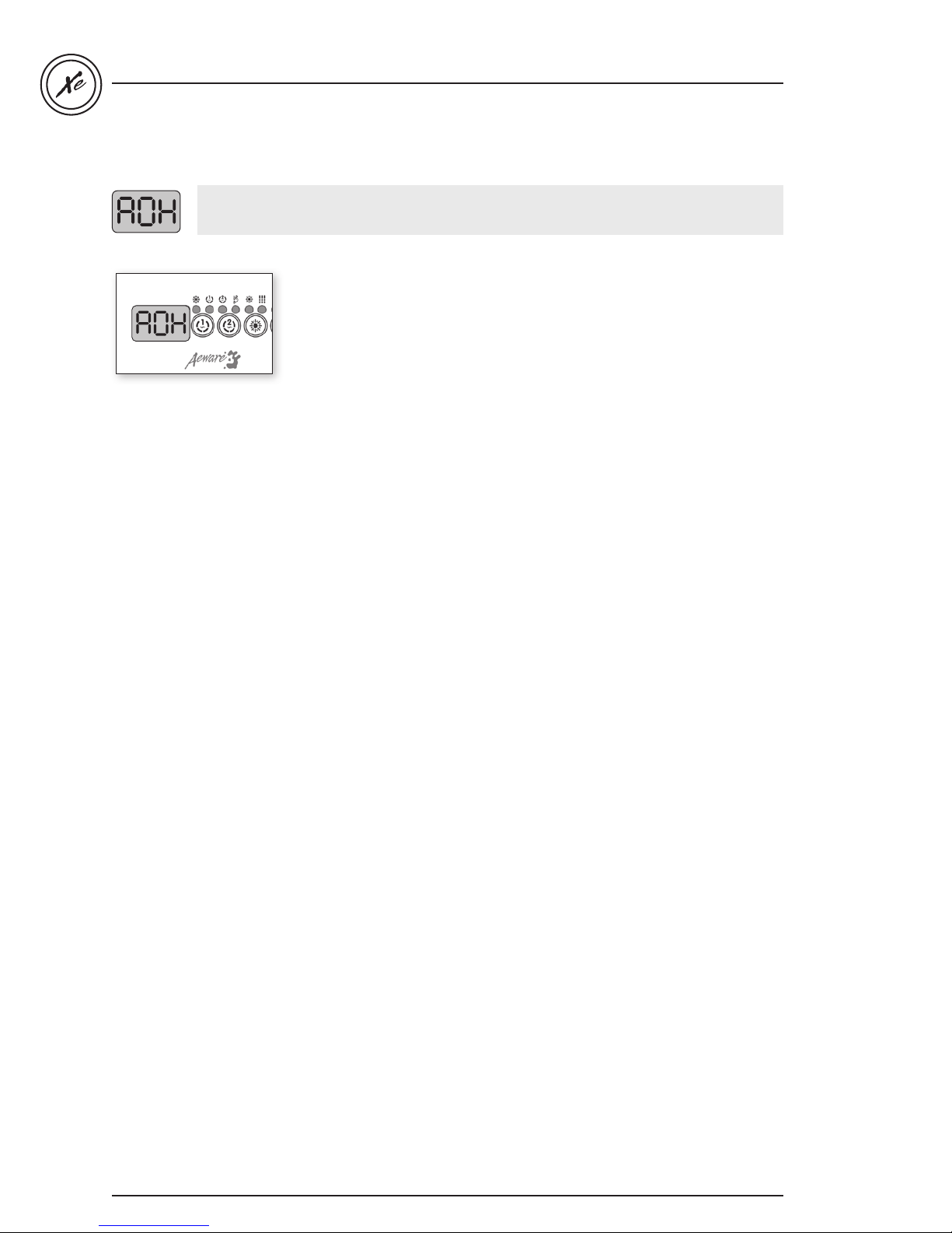
Temperature inside the spa equipment compartment is too high
Step-by-Step
• Remove spa skirt and let
system cool down, until
the error clears.
• If problem persists
replace spa pack.
in.xe TechBook
36
Page 38
in.xe TechBook
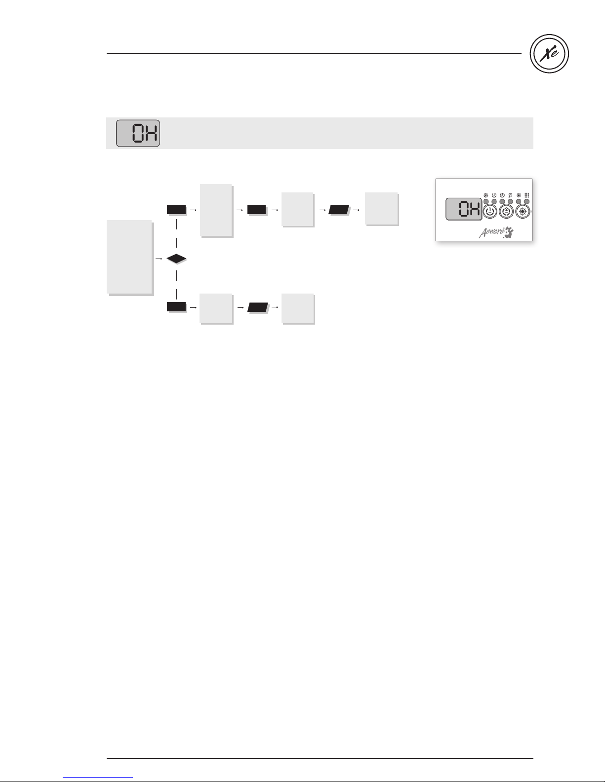
OH error message / flow chart & step-by-step
Water temp in the spa has reached 108°F
Flow chart
Measure water
temperature
with a DIGITAL
thermometer
Is the
temper
ature
reading on the
display correct?
Step-by-Step
Remove
spa cover
and let
system cool
down, until
the error
yes
clears.
Add cold
water and
lower filter
cycles.
Replace
pack,
spa
oblem
if pr
persists
• Measure water
temperature with a
no
Replace
heater,
problem
persists
if
Replace
pack,
spa
oblem
if pr
persists
DIGITAL thermometer
and compare its
reading with temp on
the display. If temp
reading is different,
replace heater.
• Remove spa cover and
let spa cool down.
• Add cold water and
lower filter cycles.
• If problem persists
replace spa pack.
3737
Page 39
98
Troubleshooting
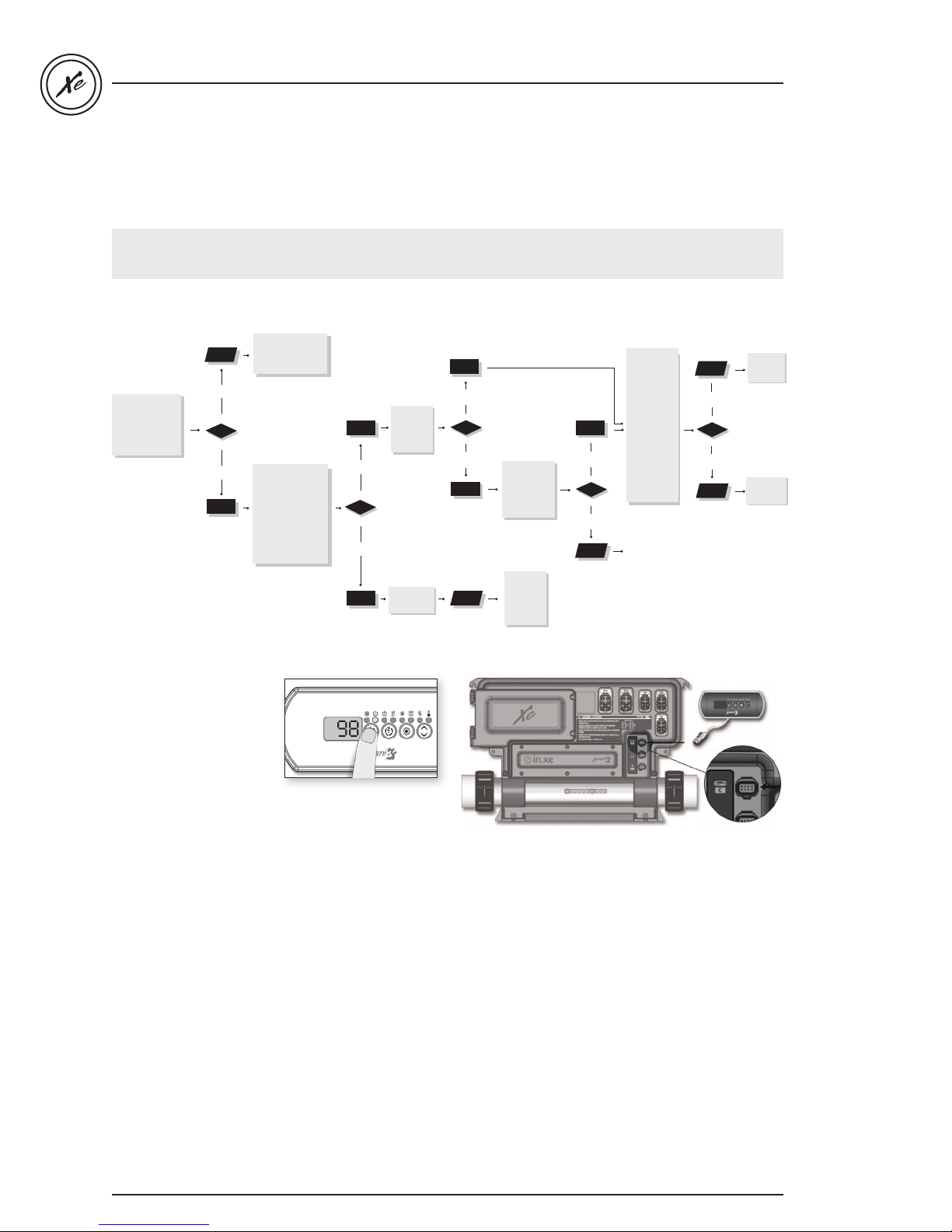
Pump 1 doesn't work / flow chart & step-by-step
If Pump 1 is not working,
follow this troubleshooting flow chart:
Flow chart
Refer to specific
section indicated
by error message.
Have any error
messages (FLO,
OH, HL etc.)
appeared on
keypad display?
yes
no
Verify if low-level
progr
properly.
Does the
indicator appear
on the keypad
display when you
press the Pump
1 key?
amming
Pump 1
is set
Is pump 1
working
in either
speed?
yes
no
in.xe TechBook
Measure
voltage on
the board
yes
no
Replace
1 fuse.
pump
Is there still a
problem?
for both
speeds.
Do you
get a 240
V reading
(or 120 V
yes
for a 120
V pump)
for both
speeds?
no
Problem
solved.
Replace
Pump 1.
yes
no
Replace
pack.
spa
Step-by-Step
Pump 1 does not work!
• Check for an error
message on keypad
display. If there is one,
refer to the specific
section indicated by
the error message.
• Verify low-level
programming
configuration.
Replace
keypad.
• Verify if the Pump 1
indicator appears on
keypad display when
you press Key 1.
If still not
working
replace
spa pack.
• If the Pump 1 indicator does not appear, use a spare
keypad to verify if keypad is defective.
If it is, replace keypad.
If not, replace spa pack.
• If Pump 1 indicator appears when Key 1 is pressed,
verify if pump works in either speed.
38
Page 40
in.xe TechBook
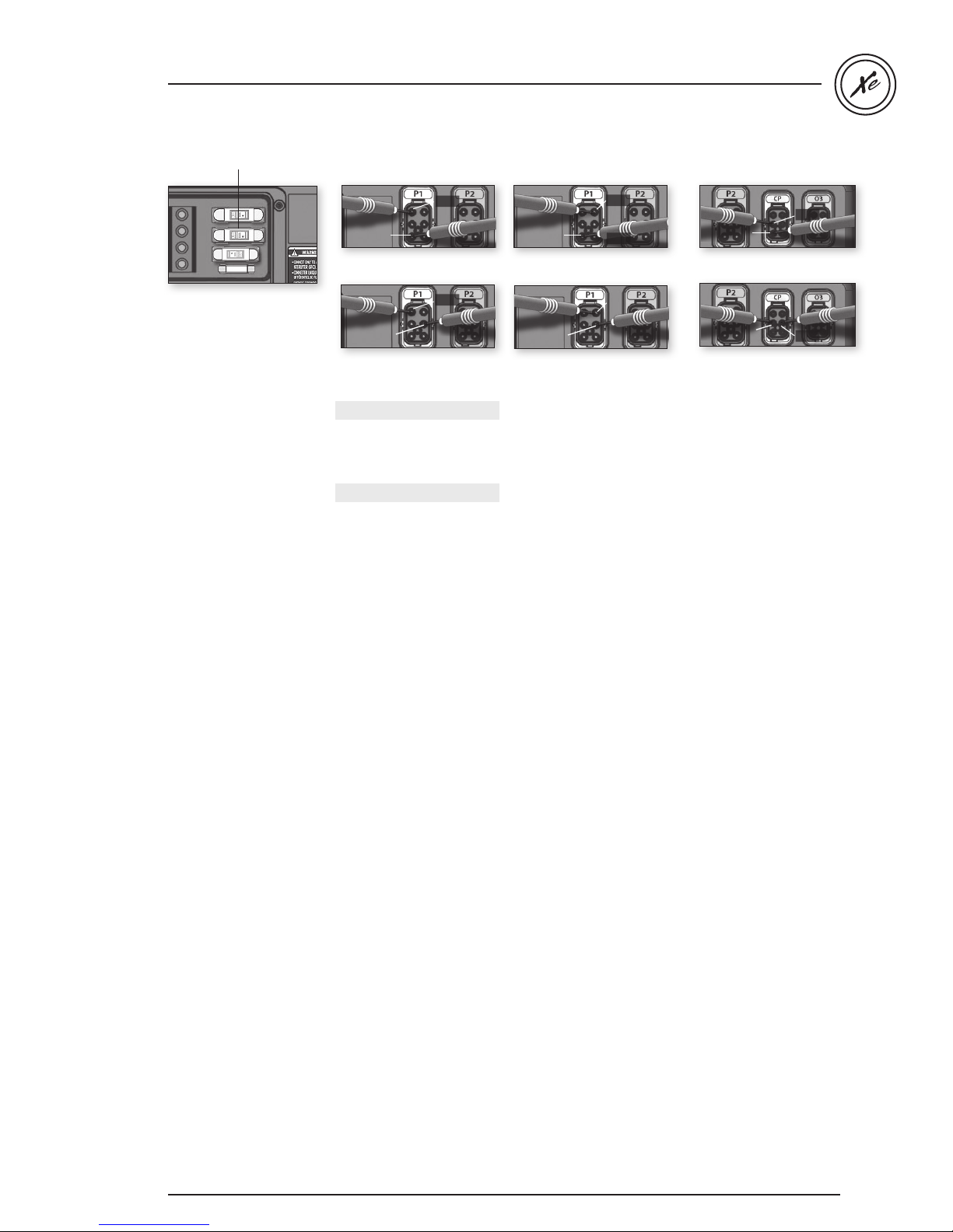
Pump 1 fuse
• If pump 1 does not
work in either speed,
replace pump 1 fuse.
• If replacing the fuse
is not effective or
if pump 1 works in
only one speed, take
voltage reading on the
corresponding in.link
connector.
Pin 1
Pin 3
240 V at P1 connector:
Pin 5
Pin 3 & Pin 1
Pin 3
120 V at P1 connector:
Pin 3 & Pin 5
Pump up to 20 A :
240 V: Pin 3 & Pin 1
120 V: Pin 3 & Pin 5
Pump up to 15 A :
240 V: Pin 2 & Pin 1
120 V: Pin 2 & Pin 5
Your reading should be:
Pin 6
Pin 1
240 V at P1 connector:
Pin 6 & Pin 1
Pin 5
120 V at P1 connector:
Pin 6
Pin 6 & Pin 5
• Turn pump 1 to low
speed and take voltage
reading between:
240 V: Pin 6 & Pin 1
120 V: Pin 6 & Pin 5
Your reading should be:
240 V for a 240 V pump
120 V for a 120 V pump
Pin 2
Pin 1
240 V at CP connector:
Pin 2 & Pin 1
Pin 2
120 V at CP connector:
Pin 2 & Pin 5
Pin 5
• If voltage is as it should
be, replace pump 1.
• If not, replace spa pack.
• Turn pump 1 to high
speed and take voltage
reading between:
240 V for a 240 V pump
120 V for a 120 V pump
39
Page 41
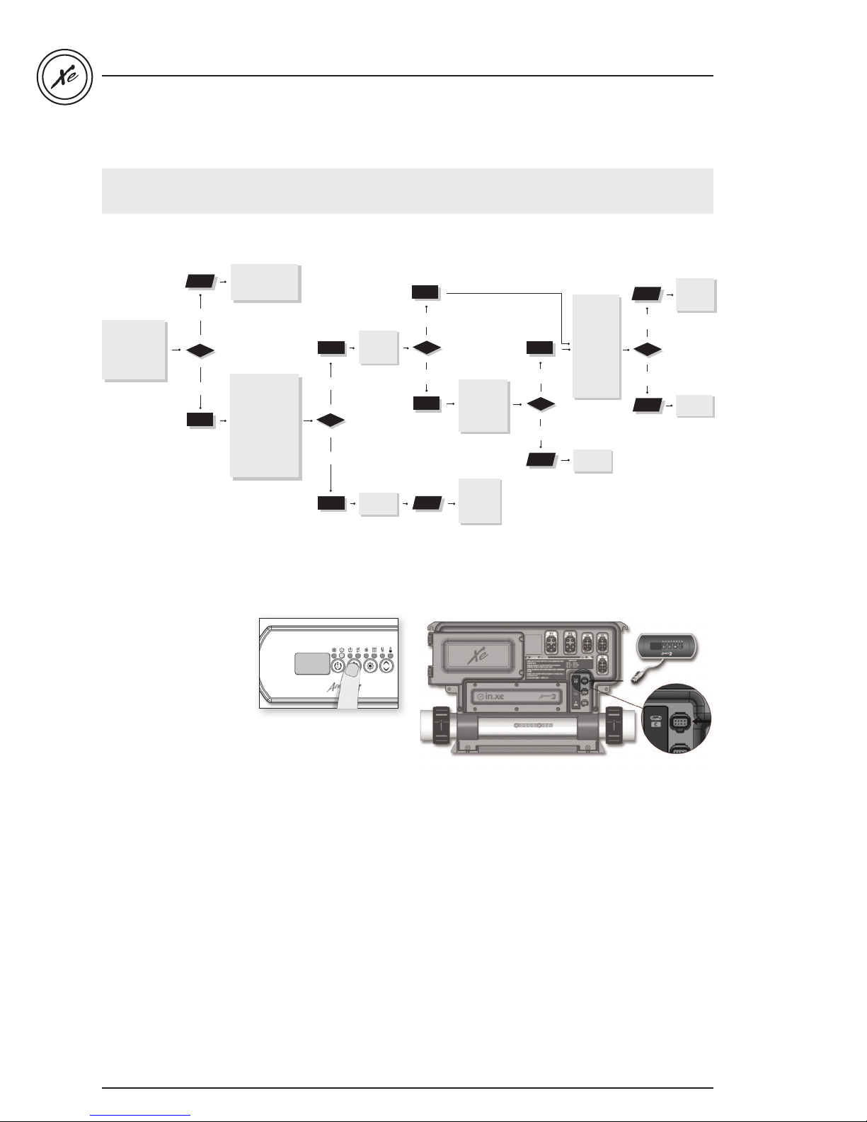
Pump 2 or blower doesn't work / flow chart & step-by-step
98
If pump 2 or blower is not working,
follow this troubleshooting flow chart:
Refer to specific
section indicated
by error message.
Have any error
messages
(OH, HR, etc.)
appeared on
keypad display?
yes
Verify if low-level
no
progr
properly.
Does Pump 2
Blower indicator
appear on keypad
display when you
press Pump 2 or
Blower key?
amming
is set
or
Is pump 2
or blower
working?
yes
no
Replace
keypad.
yes
no
Replace
blower
Is there stll a
problem?
If still not
working
replace
spa pack.
fuse.
in.xe TechBook
Replace
Measure
voltage on
the board.
Do you
get a 240
V reading
(or 120 V
yes
for a 120 V
pump)?
no
Problem
solved.
pump 2
or blower.
yes
no
Replace
spa pack.
Step-by-Step
Pump 2 or blower
is not working!
• Check for an error
message on keypad
display. If there is one,
refer to the specific
section indicated by
the error message.
• Verify low-level
programming
configuration.
• Verify if Pump 2 or
Blower indicator
appears on keypad
display when you
press Key 2.
• If Pump 2 or Blower indicators do not appear, use a
spare keypad to verify if keypad is defective.
If it is, replace keypad.
If not, replace spa pack.
• If Pump 2 indicator appears when Key 2 is
pressed, verify if pump works in either speed
(if dual speed pump).
* Only available on IN.XE-5
40
40
Page 42
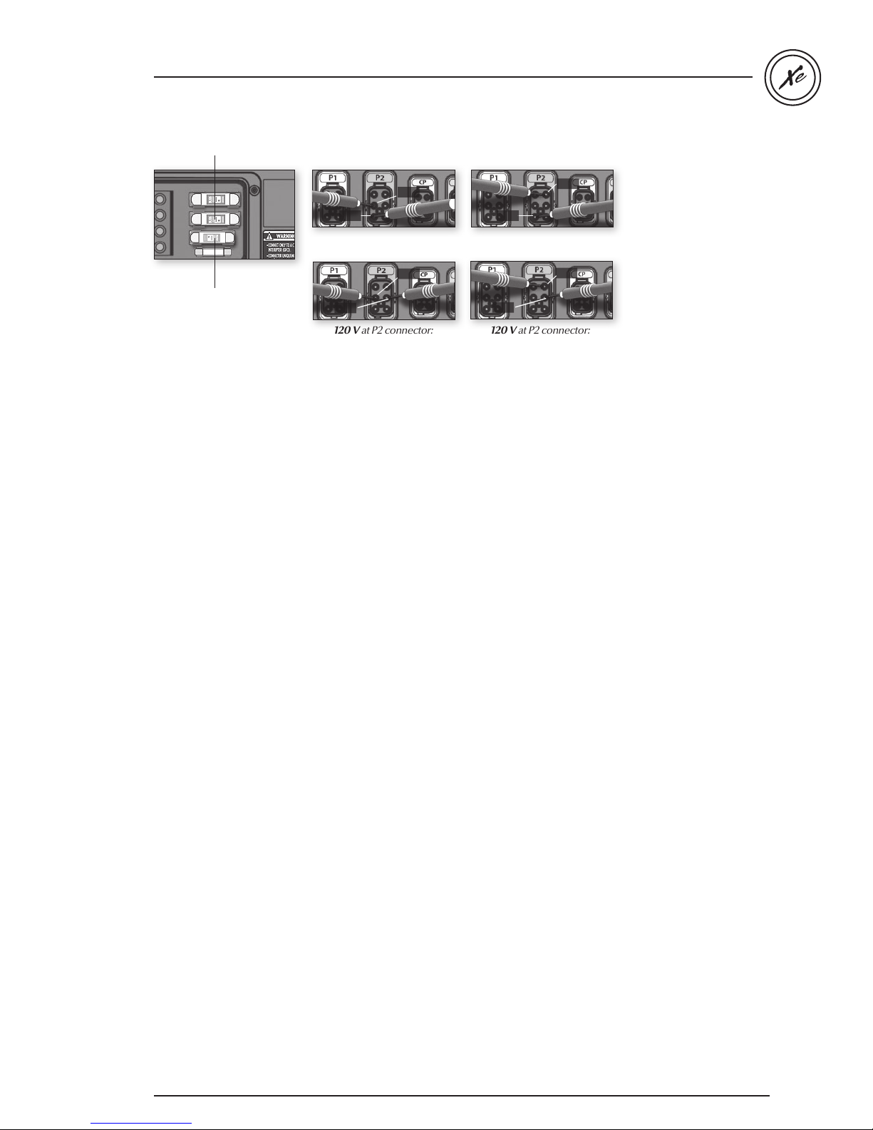
in.xe TechBook
Pump 2 fuse
Accessory fuse
• If Pump 2 or Blower
does not work even
when indicator is on,
replace pump 2 fuse or
the accessory fuse for
the blower.
• If replacing the fuse
is not effective, take
voltage reading on the
corresponding in.link
connector.
Pin 2
Pin 1
240 V at P2 connector:
Pin 2 & Pin 1
Pin 2
Pin 5
120 V at P2 connector:
Pin 2 & Pin 5
• Turn pump 2 to high
speed and take voltage
reading between:
240 V: Pin 2 & Pin 1
120 V: Pin 2 & Pin 5
Your reading should be:
240 V for a 240 V pump
120 V for a 120 V pump
Pin 6
Pin 1
240 V at P2 connector:
Pin 6 & Pin 1
Pin 6
Pin 5
120 V at P2 connector:
Pin 6 & Pin 5
• Turn pump 2 to low
speed and take voltage
reading between:
240 V: Pin 6 & Pin 1
120 V: Pin 6 & Pin 5
Your reading should be:
240 V for a 240 V pump
120 V for a 120 V pump
• Turn blower on and take
voltage reading between:
240 V: Pin 2 & Pin 1
120 V: Pin 2 & Pin 1
Your reading should be:
240 V for a 240 V blower
120 V for a 120 V blower
• If voltage is as it should be,
replace pump 2 or
blower.
• If not, replace spa pack.
* Only available on IN.XE-5
41
Page 43
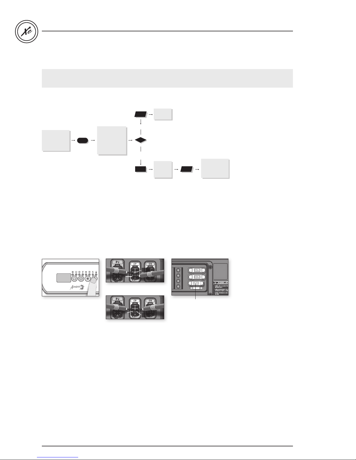
Circulation pump doesn't work / flow chart & step-by-step
98
If circulation pump is not working,
follow this troubleshooting flow chart:
Flow chart
Replace
pump.
circ
in.xe TechBook
Verify if low-level
progr
been configured
properly
amming
has
Step-by-Step
Do you read
120 V for a 120 V
circ pump (or 240
V for 240 V) on the
connector ?
Pin 1
240 V at CP connector:
yes
no
Pin 2 & Pin 1
Pin 2
Replace
accessory
Fuse
Replace spa pack
you still ar
if
en’t
getting a voltage
re
.
ading
Pin 2
If circulation pump is not
120 V at CP connector:
working:
• Verify low level
programming
configuration.
• Start circulation pump
by setting temperature
set point 2 °F higher
than actual water
temperature.
• Take voltage reading
on the corresponding
in.link connector:
240 V: Pin 2 & Pin 1
120 V: Pin 2 & Pin 5
Your reading should be:
240 V for a 240 V pump
120 V for a 120 V pump
42
42
Accessory fuse
Pin 5
Pin 2 & Pin 5
• If you don't get a voltage
reading, replace
the accessory fuse
• If changing the fuse does
not fix the problem,
replace the spa pack.
• If voltage is as it should
be, replace circulation
pump.
Page 44
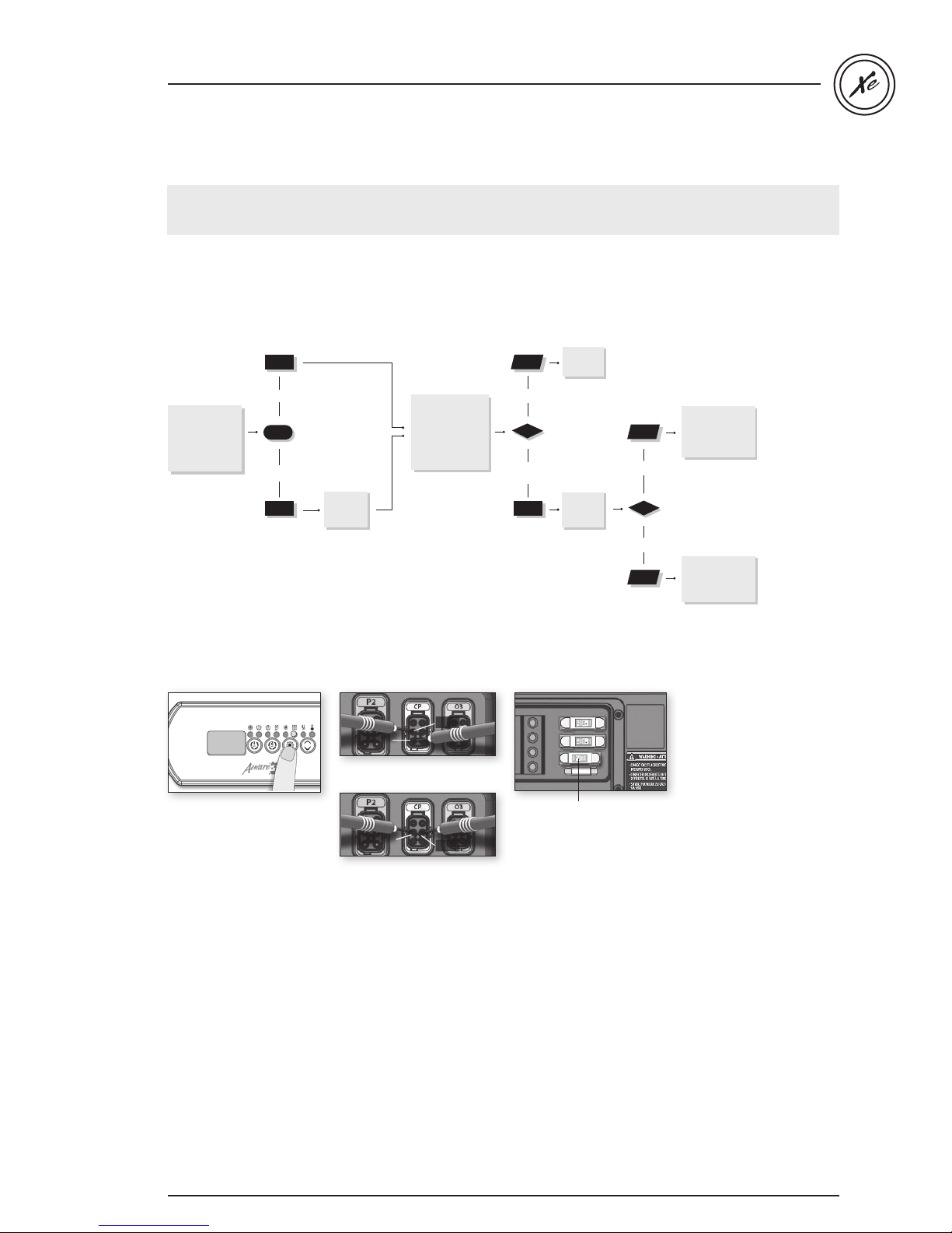
in.xe TechBook
98
Ozonator doesn't work / flow chart & step-by-step
If the ozonator is not working,
follow this troubleshooting flow chart:
Ozonator output will be shut down when pump 1, pump 2 or blower have been turned on manually.
Flow chart
Replace
.
ozonator
yes
Has Filter
Cycle indicator
appeared steady
on keypad
display?
no
Step-by-Step
If the ozonator is not
working:
Start up a
cycle.
filter
Pin 1
240 V at CP connector:
Pin 2 & Pin 1
Pin 2
120 V at CP connector:
Pin 2 & Pin 5
Do you read
120 V for a
120 V ozonator
(or 240 V for 240
V) on
the board?
Pin 2
Pin 5
yes
no
Accessory fuse
Is pump 1
working?
Replace spa pack
you still ar
if
getting a voltage
re
ading
yes
no
Refer to “Pump 1
does not Work!”
section.
en’t
.
• Verify Filter Cycle
indicator appears steady
on keypad.
• If the filter indicator is
blinking it indicates that
the filter cycle has been
interrupted.
In this case, reset the
breaker by turning the
power off and on again
to resume cycle.
• If not, start up a filter
cycle (see "Programming
filter cycles" section).
• If ozonator does not
work even when filter
cycle indicator is on,
take voltage reading
on the corresponding
in.link connector:
240 V: Pin 2 & Pin 1
120 V: Pin 2 & Pin 5
Your reading shoud be:
240 V for a 240 V
ozonator
120 V for a 120 V
ozonator
• If you don't get a voltage
reading, replace the
accessory fuse.
• If voltage is as it should
be, replace ozonator.
• If not, replace spa pack.
4343
Page 45
in.xe TechBook
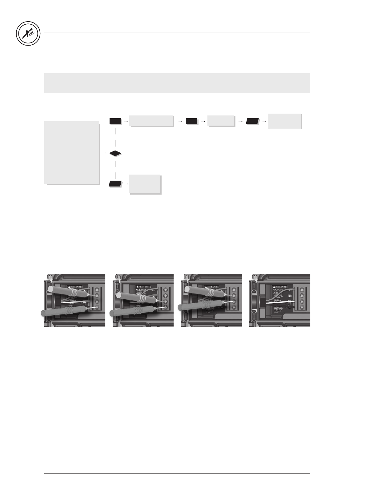
Nothing seems to work / flow chart & step-by-step
If nothing seems to work, turn off the main breaker and visually inspect power input cable, gently pulling on it
to make sure it is properly tightened. Then, follow this troubleshooting flow chart:
Flow chart
For 240 V systems:
Do you read 240 V between line
1 & line 2, 120 V between line 1 &
neutral, 120 V between line 2 &
neutral on the board?
For 120 V systems:
Do you read 120 V between
line 1 & neutral?
Step-by-Step
yes
no
Verify if k
correctly to spa pack.
There is an electrical
wiring
Call an electrician.
pr
eypad
oblem
is connected
.
Replace
transformer
fuse
Replace spa pack
there is still nothing
if
on
eypad
k
display.
Nothing seems to work!
• Verify that all
screws are properly
tightened on the
• Measure voltage
between line 1
and neutral.
terminal block.
Turn power off
• You should get 120 V.
and make sure that
all cables hold firmly
in the terminal block
if you pull on them.
• On the terminal
block, measure
voltage between line
1 and line 2.
• You should get 240 V.
44
44
• Measure voltage
between line 2
and neutral.
• You should get 120 V.
• If you do not get good
readings, this indicates
an electrical wiring
problem.
Call an electrician!
For 120 V Systems
• Measure voltage
between line 1
and neutral.
• You should get 120 V.
• If you do not get good
readings, this indicates
an electrical wiring
problem.
Call an electrician!
Page 46
in.xe TechBook
Accessory fuse
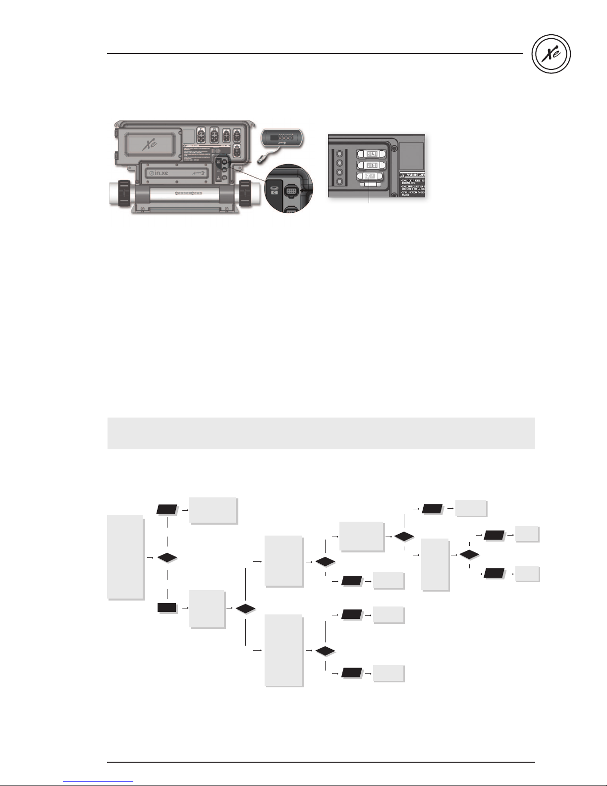
• Verify if keypad is correctly connected to the spa pack.
Spa not heating / flow chart & step-by-step
If spa is not heating,
follow this troubleshooting flow chart:
Flow chart
Refer to specific
Are there
any error
messages
on the
keypad
display?
Ensure
temp
set point is
higher
than
water
actual
temp.
error mes
section.
yes
no
Has Heater
indicator
appeared
on keypad
display?
sage
Do you get
a 240 V
reading
yes
between the
two heater
terminals
on the board?
Take water
temp and
compare with
value
temp
displayed
no
k
eypad
on
Is differ
ence
greater than
2°F?
.
• Replace transformer
fuse.
• If problem persists,
replace spa pack.
Are heater
screws properly
yes
connected to
the heater?
no
yes
no
Replace
spa pack.
Replace
heater.
System
works
fine.
yes
Tighten
screws
no
properly
Is ther
still a
problem?
Replace
heater.
yes
e
no
Replace
heater.
Problem
solved.
45
Page 47
in.xe TechBook
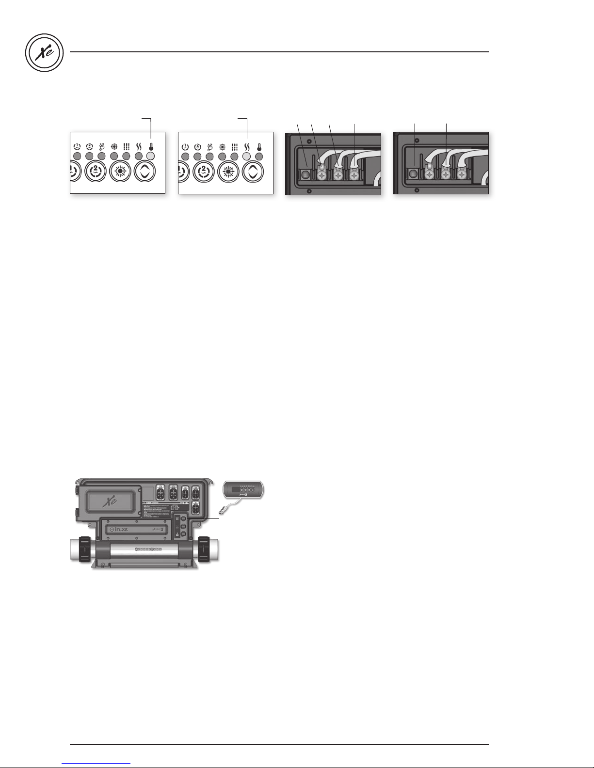
Spa not heating!
• Check for an error
message on keypad
display. If there is one,
refer to specific section indicated by the
error message.
• If there is no error
message, try to raise
water temperature by
increasing the set point
2°F higher than actual
water temperature.
Press Up key to
increase set point.
Heater indicatorset point indicator
• Verify if Heater
indicator appears on
keypad display.
• The heater indicator
will be on when heater
is on. It will flash if
more heat has been
requested, but heater
has not started yet.
L2 GroundL1N
240 V Heater (4 kW or 2 kW)
• If heater indicator lights
up on the display, take
voltage reading on the
heater terminals.
Your reading should be:
240 V: Line 1 & Line 2
120 V: Line 1 & Neutral
L1N
120 V Heater (1 kW)
• If voltage reading is
not as it should be,
verify that heater
terminals are properly
connected .
• If it is as it should be,
replace spa pack.
• In the case of the
European model
in.xe.ce only, replace
accessory fuse.
• If problem persists,
replace spa pack.
Keypad doesn't seem to work step-by-step
Keypad connector
If a keypad doesn’t seem to work:
• Verify keypad connections and try spare keypad.
• Replace keypad if problem is corrected.
• Replace in.xe if problem is not corrected.
46
Page 48
in.xe TechBook
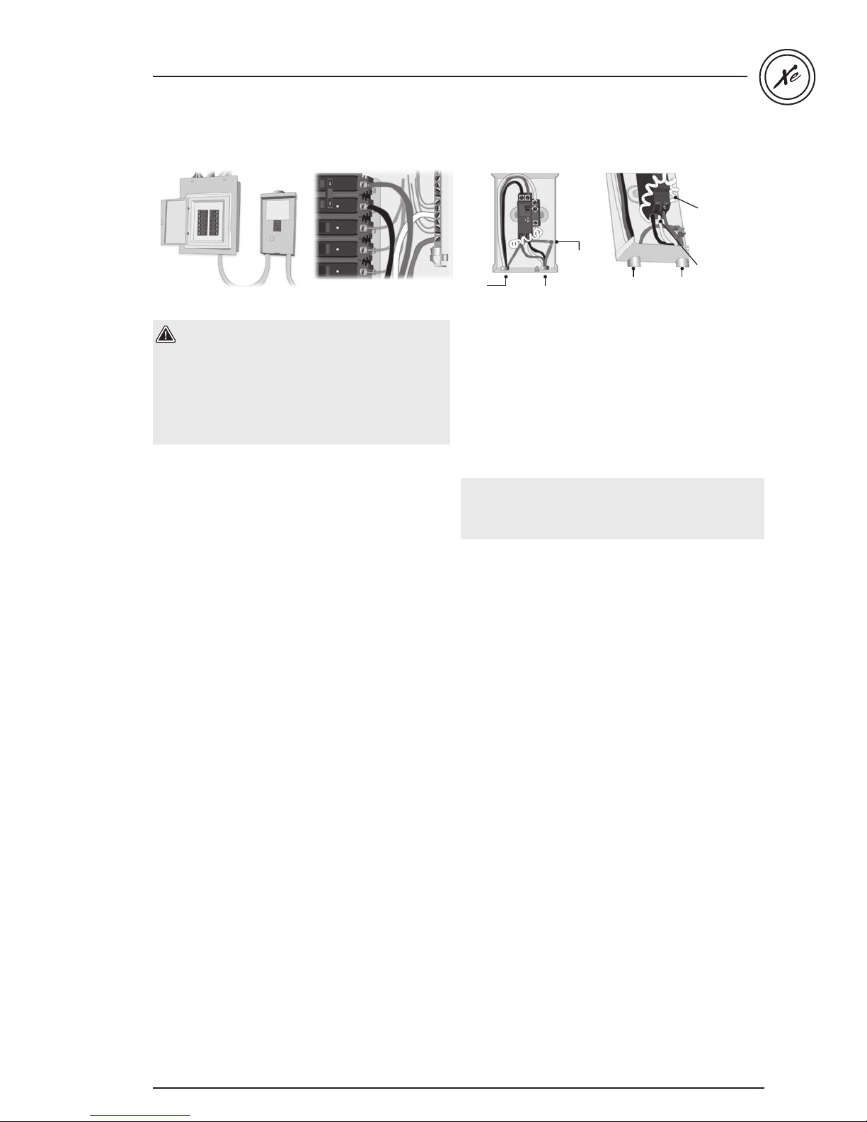
GFCI trips
Main electrical box GFCI panel
From
electrical box
To spa
Ground
wire
From
electrical box
To spa
Important
connections:
Neutral of
GFCI must be
connected to
neutral bus.
Neutral from
spa must be
connected to
breaker.
Warning!
Total current output cannot exceed total current
input rating!
There are different GFCI models used on the
market. See manufacture's instructions that come
with the GFCI for specific information. Note that all
illustrations are examples only.
Verify if GFCI is properly connected.
If it's not, verify GFCI diagram and reconnect it.
Verify in.xe pack wiring (make sure that the neutral
and the ground have not been inverted).
If the GFCI is properly connected but still tripping ,
unplug all outputs from the spa pack (pumps, blower,
heater, ozonator etc).
Reconnect one output at a time until the GFCI trips
again.
Replace defective component.
Note: Incorrect GFCI wiring may lead to a condition where the
GFCI may NOT trip when it should, causing electrical shock
hazard. All electrical installations should be done by qualified
personnel only.
47
Page 49
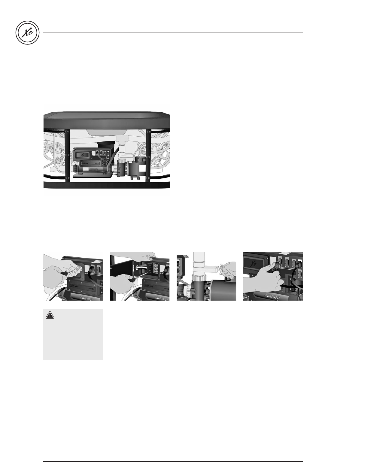
Step-by-step field replacement procedure
in.xe TechBook
in.xe
Step-by-step field replacement
procedure
As part of our technical support services, this section
provides step-by-step methods to facilitate the
replacement of in.xe spa packs in the field.
Tools needed:
• Phillips & flat screwdrivers
• Multimeter
• Open-ended adjustable wrench
• Scraper tool
• Pliers
• GFCI tester
All procedures described in this service manual
must only be performed by qualified personnel, in
accordance with the standards applicable in the country
of installation.
Warning!
When replacing an
in.xe spa pack, make
sure to turn power off
before proceeding.
With a Phillips screwdriver
or a flat screwdriver
loosen the 2 screws of
the spa pack door and
open it.
48
Disconnect incoming
power lines by loosening
the screws on the terminals
of the terminal block.
Carefully revise the spa
plumbing schematics and
identify the spa flow shut
off valves. Make sure that
both flow shut off valves
which control water
inlet before and after the
heater are closed.
Unplug all HC (high
current) outputs. e.g.:
pumps, blower or any
other accessories.
Page 50
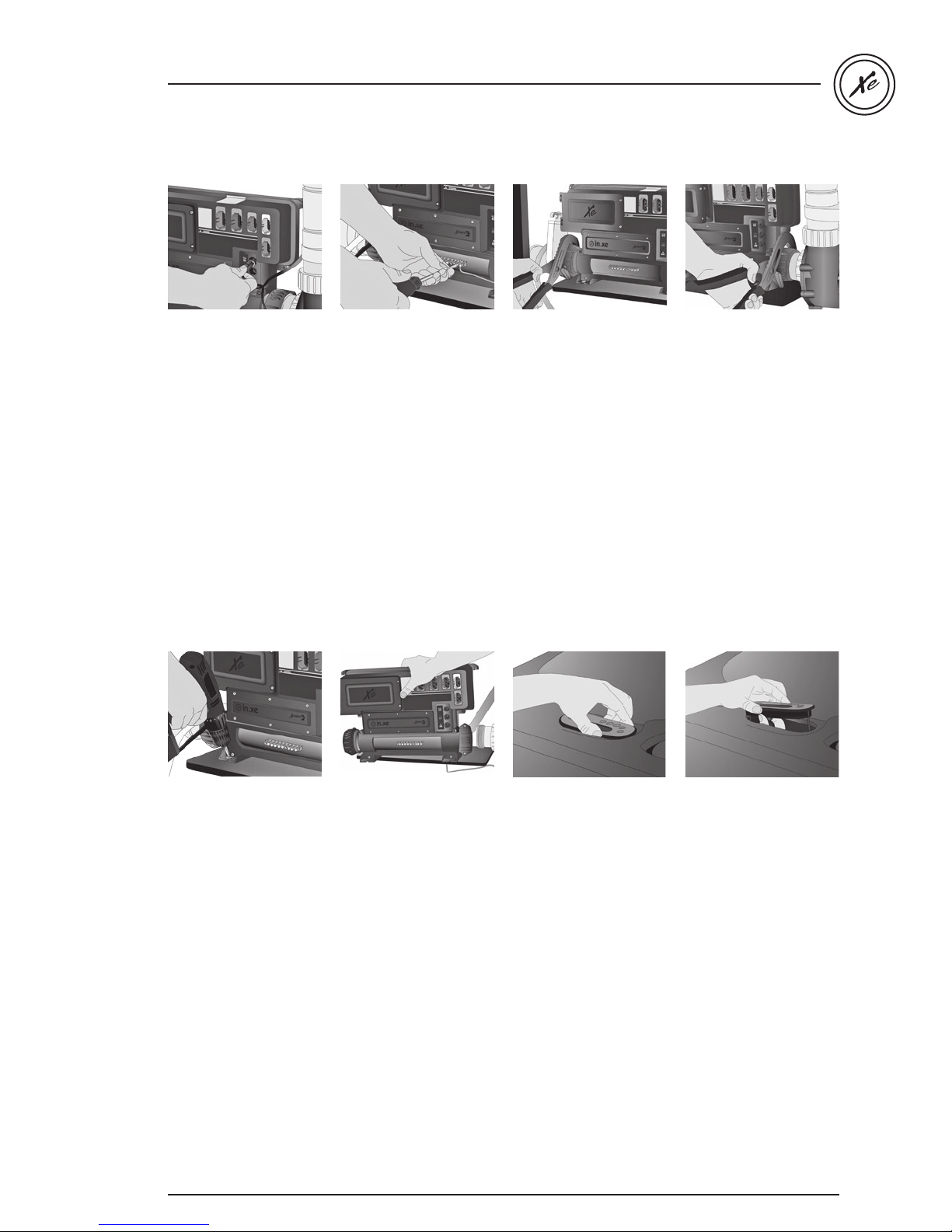
in.xe TechBook
Unplug all LC (Low
Current) outputs. e.g.:
main keypad, light or any
other accessory.
Disconnect the grounding
cable from the bonding
lug of the in.xe spa pack.
Using an open-ended
adjustable wrench loosen
both 2" plastic nuts at each
end of the in.xe heater, as
illustrated.
Remove the 2 screws that
hold the front of the unit's
feet attached to the spa
floor.
Note: the in.xe can also be
wall-mounted. For more
details on wall installation
procedure refer to the wall
installation section of the
in.xe techbook.
Release the 2" heater nuts
from both ends of the spa
piping. Release the in.xe
spa pack by sliding the unit
away from the guide plate
that holds the backside of
the unit's feet in place.
Remove the defective in.xe
spa pack from the spa.
Once that is done, remove
the old in.xe keypad from
the spa.
Note: the procedure on
keypad replacement
shown here is for
educational purposes only.
It is not always necessary to
replace the keypad, unless
it may be the cause of the
malfunctioning of the in.xe
system. Common sense
should prevail.
When removing the
old in.xe keypad, make
sure to note the exact
model, available options
etc. Ideally, the new
replacement keypad
should be of the exact
same model as the old one.
If it's not, contact our
Technical Support
Department for a keypad
compatibility list.
49
Page 51
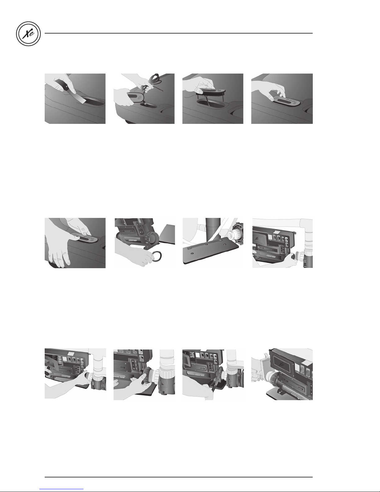
in.xe TechBook
With a scraper tool, gently
clean the installation
surface of the new
keypad. Finish by using
an alcohol saturated
paper towel to remove
any unwanted residue left
over from the old keypad.
Secure the keypad in
place. Ensure that its
adhesive strip is properly
glued by pressing evenly
with your finger over the
entire surface.
Feed the cable of the new
keypad through the hole
opening in the spa.
Orient the cable's
connector towards the
in.xe pack to facilitate its
connection later.
Place a rubber 2" O'ring
gasket at the end of each
heater nut, to prevent
water leakage between
the heater nuts and the 2”
PVC heater tailpieces.
Insert the keypad into the
opening.
When installing the new
in.xe spa pack, slide back
side of the unit's feet into
the guide plate.
Peel off the double-sided
tape protective layer from
the back of the keypad.
Make sure that the keypad
is well aligned and rests
perfectly in the recess of
the spa.
Install the new in.xe spa
pack in the spa plumbing.
Screw fittings to join to the
spa pipe system. Make
sure that the piping and
nut threads are not over
tightened.
50
Finally, follow the same
procedure in reverse order
to connect replacement
in.xe spa pack.
Page 52
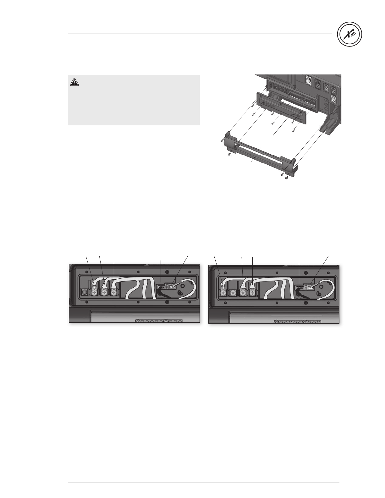
in.xe TechBook
How to replace the heater
Warning!
Before starting removal procedure be sure to:
• Turn off electric power to the the unit.
• Ensure spa water valves are closed
(or that the spa is drained).
Using a Phillips screwdriver, loosen the 6 screws that
hold the heater connections door in place.
Once the screws are removed, disengage the heater
connections door.
Loosen and remove the 4 screws and disengage
the heater bracket.
heater
connections
bracket
heater
door
L2 L1 Ground HL Probe &
240 V Heater (4 kW or 2 kW)
Temp Probe
in.flo
Use a Phillips screwdriver to loosen the terminals and
remove all electrical heater connections:
Neutral Line (N), Line 1 (L1), Line 2 (L2) and Ground Line
(Ground).
Manually remove the HL probe & Temp probe connector.
Manually remove the in.flo connector.
Be careful not to damage any connector by twisting
or pulling too hard.
L1N Ground HL Probe &
120 V Heater (1 kW)
Temp Probe
in.flo
51
Page 53
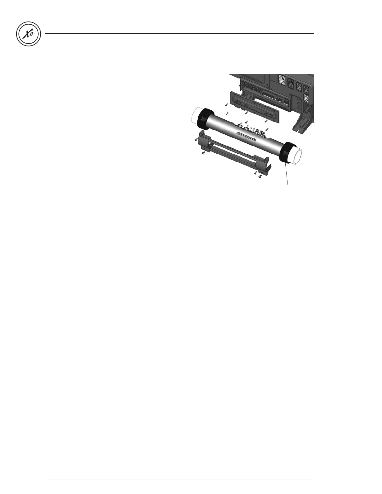
After disconnecting all electrical heater connections,
loosen and remove the 2 heater nuts retaining
the heater.
Disengage heater from the in.xe pack by slightly twisting
in such a way that the bottom of the heater comes out
first. Pull the heater away from the pack.
Replace the defective heater with a new one, and repeat
the same procedure in reverse order to reconnect the
replacement heater to the in.xe pack.
in.xe TechBook
Heater nut
52
Page 54
in.xe TechBook
Specifications
Environmental ratings:
Operating temperature: North American model in.xe:
32˚F (0˚C) to 140˚F (60˚C) for pump 1 up to 15 A
32˚F (0˚C) to 122˚F (50˚C) for pump 1 up to 20 A
European model in.xe.ce:
for single-phase system (32 A Max) or 2-phase (2 x 16 A)
32˚F (0˚C) to 140˚F (60˚C)
for single-phase system (40 A Max) or 2-phase (2 x 20 A)
32˚F (0˚C) to 122˚F (50˚C)
(* Controller must be installed under the spa skirt)
Storage temperature: -13°F (-25°C) to 185°F (85°C)
Humidity: Up to 85% RH, non condensing
Mechanical:
Weight: 10.5 lb (4.76 kg)
Dimensions (W x H x D): 17.38" x 11.75" x 5.1" (441.5x298.5 x129 mm)
UL/CSA Standards:
UL 1563 Fifth Ed.
UL File: E182156
CSA No. 22.2 - 218.1-M89.
TUV Standards:
EN/IEC 60335 - 2 - 60: 2003/2002 - EN/IEC 60335 - 1: 2002/2001
(incl. Corr. & Am. up to 2004)
EN55014-1
EN55014-2
EN61000-3-2
EN61000-3-3
The in.xe.ce is lab tested to IPx5 enclosure protection levels.
IPx5 level of waterproofing is conditional on 3 items:
• Both front covers (heater and input wiring) are closed and screwed shut.
• A suitable waterproof strain-relief/bushing is used for the cable entry into the pack.
• Any unused in.link connection (HC, LC, or low voltage) is plugged with the appropriate blank plug.
53
Page 55
in.xe UL/CSA electrical specifications
Input rating: 120/240 V nominal (+ 5/- 10 %) (2 lines required with neutral) 48 A Max,
or: 120 V nominal only (+ 5/- 10%) single line with neutral) 16 A Max,
60Hz nominal (+ 1. 5 / -1.0 Hz).
Output ratings:
Output Voltage Maximum Current Typical Device
Out 1 120/240 V 20 FLA/70 LRA (in-rush) Pump 1 High Speed
120/240 V 15 FLA/60 LRA (in-rush) Pump 1 Low Speed
Out 2* 240 V 15 FLA/60 LRA (in-rush) Pump 2
Out 3* 120/240 V 6 FLA/10 A (CP)/Blower
Out 4 120/240 V 6 FLA/10 A Ozone Generator
Out 5 120/240 V 10 A (always ON) Audio/Video device
L1 12 V AC 1 A Light
CO Communications port Comm.connector (in.stik)
C1 Tub side controller
in.xe TechBook
heat.wav rating:
Voltage: 120 or 240 V, 60 Hz
Wattage: 17A resistive (4 kW at 240 V)
8.5 A resistive (1kW at 120 V)
Flow rate: Minimum of 18 GPM is required
Important:
• All low voltage acccessories use + 5 V DC and/or + 12 V DC.
• All low voltage acccessories combined: 150 mA max, on + 12 V DC.
• The maximum amperage for outputs 3 to 5 cannot exceed 12 A.
in.xe.ce TUV electrical specifications
Input rating: 230/400 V nominal (+ 5/- 10 %) (2-phase system) 20 A Max per phase
or: 230 V nominal (+ 5/- 10 %) (single-phase system) 40 A Max
Output ratings:
Output Voltage Maximum Current Typical Device
Out 1 230 V 15 FLA/60 LRA (in-rush) Pump 1 High & Low
Out 2* 230 V 15 FLA/60 LRA (in-rush) Pump 2
Out 3* 230 V 6 FLA/10 A (CP)/Blower
Out 4 230 V 6 FLA/10 A Ozone Generator
Out 5 230 V 10 A (always ON) Audio/Video device
L1 12 V AC 1 A Light
CO Communications port Comm.connector (in.stik)
C1 Tub side controller
heat.wav rating:
Voltage: 230 V, 50 Hz
Wattage: 8.7 A resistive (2kW at 230 V)
5.7 A resistive (1.3 kW at 230 V)
16.5 A resistive (3.8 kW at 230 V)
Flow rate: Minimum of 18 GPM is required
54
* Only available on IN.XE-5-XX-XXX
Page 56

Gecko Alliance
450 des Canetons, Quebec City (Qc), G2E 5W6 Canada, 1.800.78.GECKO
9225 Stellar Court, Corona, CA 92883 USA, 951.667.2000
www.geckoalliance.com
Printed in Canada 09-2013
9919-100760-C
Rev. 09-2013
© Groupe Gecko Alliance Inc., 2013
All trademarks or registered trademarks
are the property of their respective owners.
 Loading...