

Page 1
TechBook
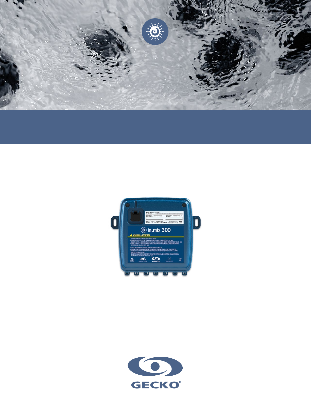
in.mix 300
LED controller & power supply
a lighting control console at your fingertips
up to 3 different color zones
the power to illuminate
Page 2

Table of contents
Safety instructions ............................................................................................................................................................ 2
Warnings ......................................................................................................................................................................... 3
Introduction ..................................................................................................................................................................... 5
Overview .......................................................................................................................................................................... 6
Dimensions ...................................................................................................................................................................... 7
Installation ....................................................................................................................................................................... 8
Connections
- Preparation ......................................................................................................................................................... 9
- Compatible LED lights ...................................................................................................................................... 11
- Other compatible LED lights ............................................................................................................................. 12
- Other connections ............................................................................................................................................ 14
Compatible keypads ...................................................................................................................................................... 15
Troubleshooting ............................................................................................................................................................. 16
Specifications ................................................................................................................................................................ 17
1
Page 3
Safety instructions
CAUTION
RISK OF ELECTRIC SHOCK
DO NOT OPEN
CAUTION: TO REDUCE THE RISK OF ELECTRIC SHOCK, DO NOT REMOVE SCREWS ON THE BACK OF
THE ENCLOSURE. NO USER-SERVICEABLE PARTS INSIDE. REFER SERVICING TO QUALIFIED SERVICE
PERSONNEL.
The lightning flash with the arrowhead symbol within an equilateral triangle is intended to alert the user to
the presence of uninsulated ‘‘dangerous voltage’’ within the product’s enclosure that may be of sufficient
magnitude to constitute a risk of electric shock to persons.
The exclamation point within an equilateral triangle is intended to alert the user to the presence of important
operating and maintenance (servicing) instructions in the service literature accompanying this appliance.
IMPORTANT SAFETY INSTRUCTIONS:
For your own safety please read the following important safety instructions carefully before attempting to
connect this unit to the mains power supply. They will also enable you to get the best performance from and
prolong the life of the unit:
* READ THESE INSTRUCTIONS.
* KEEP THESE INSTRUCTIONS.
* HEED ALL WARNINGS.
* FOLLOW ALL INSTRUCTIONS.
* CLEAN ONLY WITH DRY CLOTH. BEWARE THE APPLICATION OF SOME PRODUCTS COMMONLY USED AGAINST
CORROSION (SUCH AS WD-40 FAMILY PRODUCTS) AS THEY COULD DAMAGE THE ENCLOSURE, DUE TO A NEGATIVE
CHEMICAL REACTION BETWEEN SOME INDUSTRIAL OILS AND ITS PLASTIC ENCLOSURE. ANY OTHER MATERIALS WHICH
MAY COME IN CONTACT WITH THE ENCLOSURE MUST BE CAREFULLY EVALUATED UNDER END USE CONDITIONS FOR
COMPATIBILITY.
* DO NOT INSTALL NEAR ANY HEAT SOURCES. CLEARANCE AND MINIMUM DISTANCE BETWEEN THE VARIOUS PARTS OF
THE APPLIANCE AND THE SURROUNDING STRUCTURE ARE NOT SPECIFIED AS LONG AS THEY ARE SUFFICIENT SO THAT
THE AMBIENT TEMPERATURE AROUND THE APPARATUS DOES NOT EXCEED 140°F (60°C).
* DO NOT DEFEAT THE SAFETY PURPOSE OF THE POLARIZED OR GROUNDING-TYPE PLUG. A POLARIZED PLUG HAS TWO
BLADES WITH ONE WIDER THAN THE OTHER. A GROUNDING TYPE PLUG HAS TWO BLADES AND A THIRD GROUNDING
PRONG. THE WIDE BLADE OR THE THIRD PRONG ARE PROVIDED FOR YOUR SAFETY. IF THE PROVIDED PLUG DOES NOT
FIT INTO YOUR OUTLET, CONSULT AN ELECTRICIAN FOR REPLACEMENT OF THE OBSOLETE OUTLET.
* PROTECT THE POWER CORD FROM BEING WALKED ON OR PINCHED PARTICULARLY AT PLUGS, CONVENIENCE
RECEPTACLES, AND THE POINT WHERE THEY EXIT FROM THE APPARATUS.
* ONLY USE ATTACHMENTS/ACCESSORIES SPECIFIED BY THE MANUFACTURER.
* UNPLUG THIS APPARATUS DURING LIGHTNING STORMS OR WHEN UNUSED FOR LONG PERIODS OF TIME.
* REFER ALL SERVICING TO QUALIFIED SERVICE PERSONNEL. SERVICING IS REQUIRED WHEN THE APPARATUS HAS
BEEN DAMAGED IN ANY WAY, SUCH AS POWER-SUPPLY CORD OR PLUG IS DAMAGED, LIQUID HAS BEEN SPILLED OR
OBJECTS HAVE FALLEN INTO THE APPARATUS, THE APPARATUS HAS BEEN EXPOSED TO RAIN OR MOISTURE, DOES NOT
OPERATE NORMALLY, OR HAS BEEN DROPPED.
* THIS APPLIANCE INCORPORATES AN EARTH CONNECTION FOR FUNCTIONAL PURPOSES ONLY.
Aeware®, Gecko®, and their respective logos are Registered Trademarks of Gecko Alliance Group.
in.mix 300™, in.stream 2™, in.k1000™, in.k800™, in.k500™ and their respective logos are Trademarks of Gecko Alliance Group.
All other product or company names that may be mentioned in this publication are tradenames, trademarks or registered trademarks
of their respective owners.
2
Page 4
Warnings
WARNINGS:
Before installing or connecting the unit, please read the following.
* DO NOT DISASSEMBLE OR ALTER THE APPARATUS.
* DO NOT USE FOAM TO ISOLATE THE UNIT.
* TURN POWER OFF BEFORE SERVICING OR MODIFYING ANY CABLE CONNECTIONS IN THIS UNIT.
* TO PREVENT ELECTRIC SHOCK HAZARD AND/OR WATER DAMAGE TO THIS APPARATUS, ALL CONDUITS MUST BE
PLUGGED WITH THE ATTACHED GASKET.
* IN.MIX ENCLOSURE SHALL BE LOCATED ABOVE THE FLOOD ZONE WHERE THEY ARE UNLIKELY TO BE
SUBMERGED IN THE EVENT THE SPA IS OVERFILLED (OR SIMILAR ABNORMAL CONDITION OCCURENCE).
* PRODUCT MUST BE DISPOSED OF SEPARATELY FROM NORMAL HOUSEHOLD IN ACCORDANCE WITH LOCAL
WASTE DISPOSAL LEGISLATION.
WARNINGS:
When this equipment is provided as an audio/video components for spas, U1563 - 6th edition requires
that the following instructions (or equivalent) be provided as part of the instruction manual for the spa
equipment.
* "CAUTION – RISK OF ELECTRIC SHOCK. DO NOT LEAVE COMPARTMENT DOOR OPEN";
* "CAUTION – RISK OF ELECTRIC SHOCK. REPLACE COMPONENTS ONLY WITH IDENTICAL COMPONENTS";
* WARNING – TO PREVENT DAMAGE, FIRE AND ELECTOCUTION DO NOT CONNECT LIGHT ASSEMBLY CABLE THAT HAS
NOT BEEN APPROVED BY GECKO
* DO NOT SERVICE THIS PRODUCT YOURSELF AS OPENING OR REMOVING COVERS MAY EXPOSE YOU TO
DANGEROUS VOLTAGE OR OTHER RISK OF INJURY. REFER ALL SERVICING TO QUALIFIED SERVICE PERSONNEL.
* WHEN THE POWER SUPPLY CONNECTIONS OR POWER SUPPLY CORD(S) ARE DAMAGED; IF WATER IS ENTERING THE
IN.MIX ENCLOSURE OR ANY ELECTRICAL EQUIPMENT COMPARTMENT AREA; IF THE PROTECTIVE SHIELDS OR BARRIERS
ARE SHOWING SIGNS OF DETERIORATION; OR IF THERE ARE SIGNS OF OTHER POTENTIAL DAMAGE TO THE UNIT, TURN
OFF THE UNIT AND REFER SERVICING TO A QUALIFIED SERVICE PERSONNEL.
* THIS UNIT SHOULD BE SUBJECTED TO PERIODIC ROUTINE MAINTENANCE (FOR EXAMPLE, ONCE EVERY 3 MONTHS) TO
MAKE SURE THAT THE UNIT IS OPERATING PROPERLY.
* PRODUCT MUST BE DISPOSED OF SEPARATELY FROM NORMAL HOUSEHOLD IN ACCORDANCE WITH LOCAL WASTE
DISPOSAL LEGISLATION.
3
Page 5

4
Page 6
Introduction
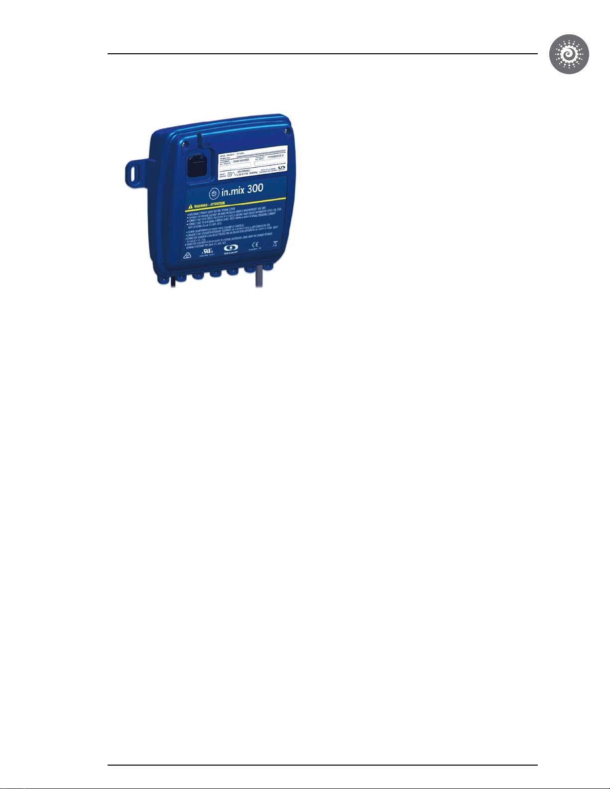
in.mix 300
LED controller & power supply
for your spa
The in.mix 300 provides the low voltage required to power
the RGB LED fixture of your spa.
When connected to one of our X or Y series control
systems for spas and hot tubs, in.mix transforms our
in.k1000 touch screen and in.k800 color display keypads
in real lighting consoles with a perfect interface. Create
your personalized ambiance easily with an infinite
selection of colors and a light intensity dimmer.
The in.mix comes with a built-in power supply and can be
connected to a 120V or 240V output of your spa’s control
system. It can drive up to 100 points of RGB in 3 zones
and illuminate the water of your spa or create accent
colors around it.
5
Page 7
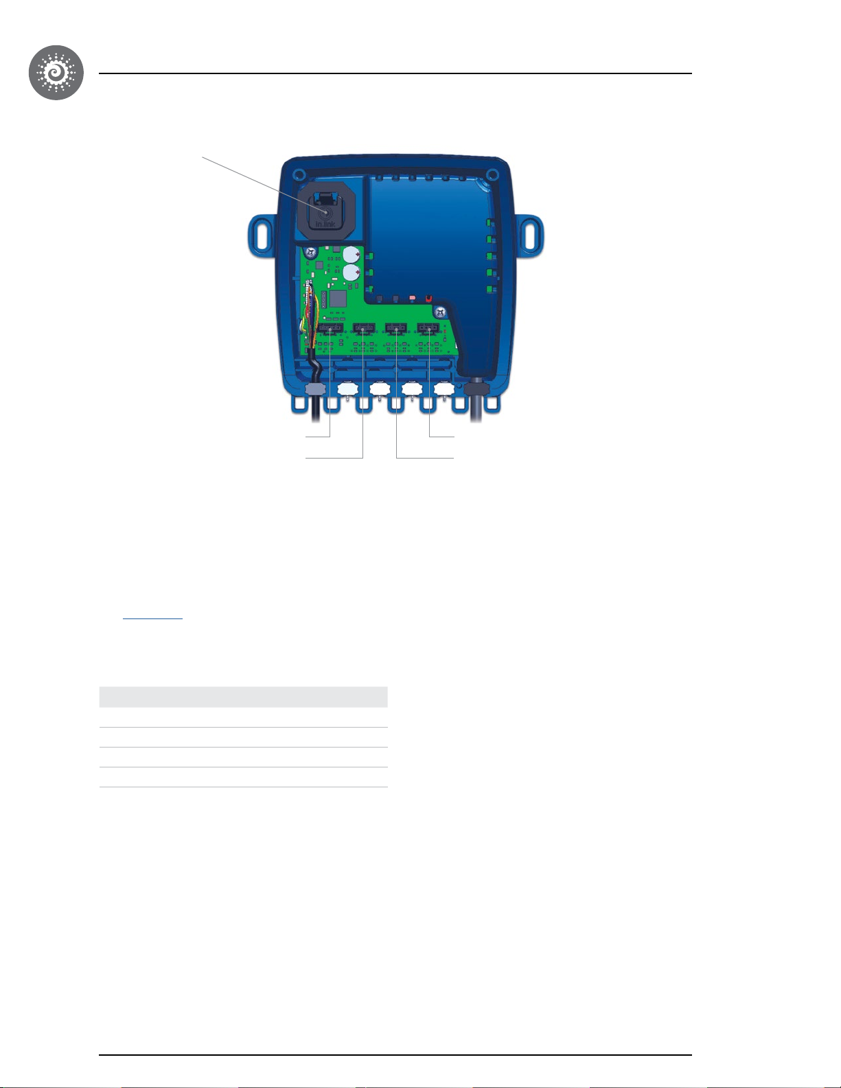
Overview
CO port
OUT 1
OUT 2
The in.mix 300 module supports 3 LED zones.
Zone 1 supports 2 types of connexions (A and B). The type A connection is made for 5 pin LEDs and the type B
connection is for 4 pin LEDs (see page 9 for the pin functions). It is important to note that these 2 connections will always
output the same color, since they are in the same Zone 1.
All zones may be used at the same time, but the total permissible power should always be respected
(see connections section).
Table of correspondence between zones and connections:
Connector Zone
OUT1 1
OUT2 1
OUT3 2
OUT4 3
This is the default zone assignment for each output. The low level configuration of the pack can be configured for a
different zone assignment. Please refer to the low level specifications.
OUT 4
OUT 3
Status light (optional)
When you assign a zone to have the status light functionality, it can help you diagnose problems on your spa.
• Blue light flashing: Maintenance reminder
• Blue light on: Everything is normal
• Red light flashing: You've lost communication on your spa
• Red light on: You have a problem on your spa
6
Page 8
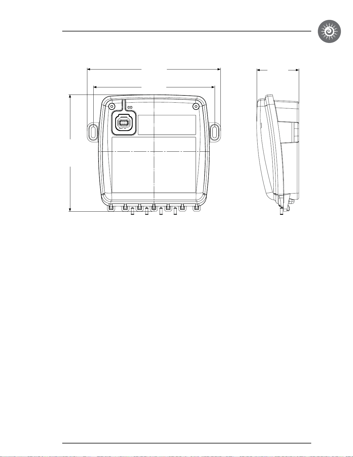
Dimensions
6.13"
(156 mm)
7.03"
(179 mm)
6.38"
(162 mm)
Front view
2.22"
(56 mm)
Side view
7
Page 9
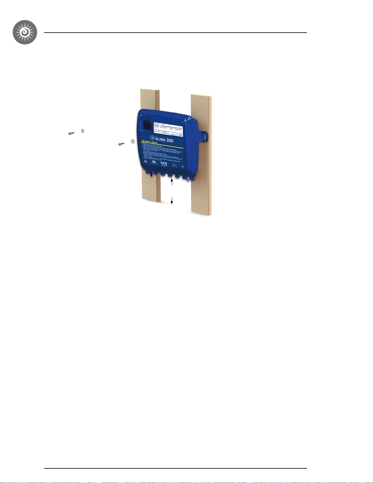
Installation
To prevent water from getting inside the device, the in.mix 300 should be installed on a vertical surface as shown below:
4"
(100 mm)
Secure the in.mix 300
Firmly attach upper mounting holes one at a time on each
side of the apparatus.
The following material is recommended:
2 - # 10 screws of appropriate length with round,
truss or pan head.
2 - washers 0.5" OD x .0625” thickness
(12 mm OD x 1.5 mm)
8
Page 10
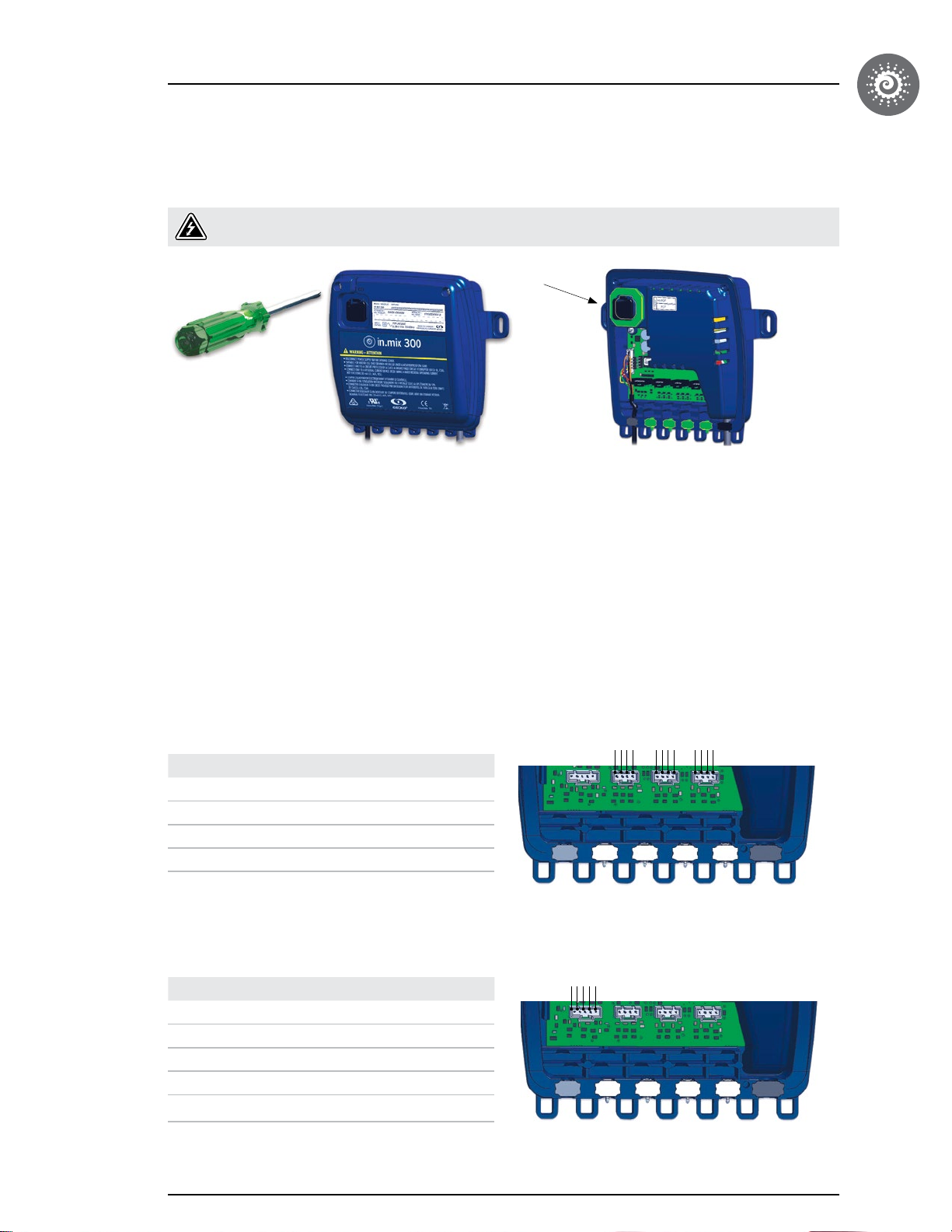
Connections
Preparation
To prevent electric shock hazard, do not connect to main power supply while the cover is removed.
Gasket
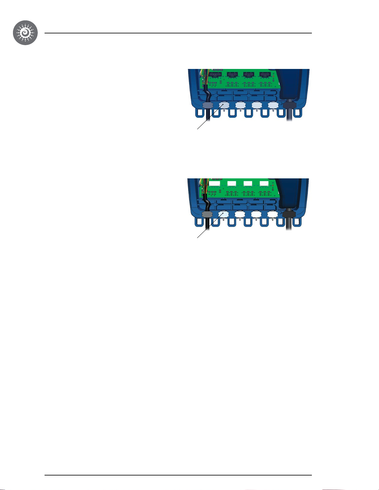
Remove the cover screws from the front of the apparatus with a Phillips screw driver.
Before closing, please make sure the in.mix 300 gasket is well in place.
Remove all seals and insert LED wire. Repeat for every LED lights you need to connect.
The in.mix 300 powers the LEDs with DC current**.
No matter the quantity of LEDs or their placement
(Out 1 to Out 4), a maximum of 1.6A can be supplied
by the in.mix 300. Every color (red, green or blue) is
controlled independently through switching. The current
limiting resistors are not supplied, they must therefore be
in the LEDs. One must not connect a LED (or other light)
directly to any zone.
Connectors Out 2, Out 3 and Out 4 offer the following connections. The switching transistors are on the in.mix 300.
1 1 12 2 23 3 34 4 4
Pin Function
1 BLUE (switched ground)
2 GREEN (switched ground)
3 RED (switched ground)
4 V
cc
Connector Out 1 offers the following connections. For this output, the switching transistors are included with the LEDs,
which is standard with “cluster” type models.
Pin Function
1 2 34 5
1 BLUE (TTL output, High=on)
2 GREEN (TTL output, High=on)
3 RED (TTL output, High = on)
4 +12V
5 OV
** The output voltage is switched to simulate the power of a
5V output.
9
Page 11
Connections
Connection for the 5VDC Output version:
The in.mix 300 is compatible with Molex’s SL series
LED connectors.
Female Housing 4 Pos : #50-57-9404
Female Housing 5 Pos : #50-57-9405
Pin Female part number (AWG 22-24) : #16-02-0102
** The output voltage is switched to simulate the power of a
5V output.
Connection for the 12VDC Output version:
The in.mix 300 is compatible with Molex's SL series
LED connectors.
Female Housing 4 POS : #3-643814-4 (AWG24)
Female Housing 5 POS: #3-643814-5 (AWG24)
seal
seal
in.mix 300 - 5 volts
in.mix 300 - 12 volts
10
Page 12
Connections
Compatible LED lights
Contact Gecko Alliance to determine if the LED models you plan on using are compatible.
If J&J Electronics Inc.’s Spyder LEDs from their ColorCHOICE™ series are used, a maximum of 100 are supported by
the in.mix-300. They may be distributed in any way through the 3 Zones.
The Out 1 is compatible with the J&J cluster.
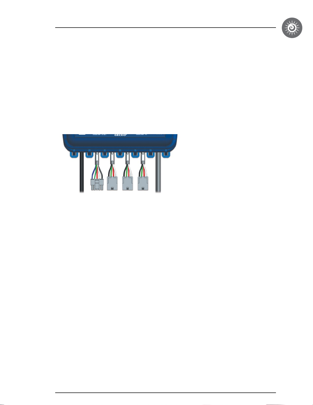
If choosing J&J Electronics, please note the in.mix 300 comes in "plug and play" version (#0609-521005) with cables
included as seen here:
Different options are available according to the situation. Please note you can only have a "plug and play" model with J&J
Electronics.
11
Page 13
Connections
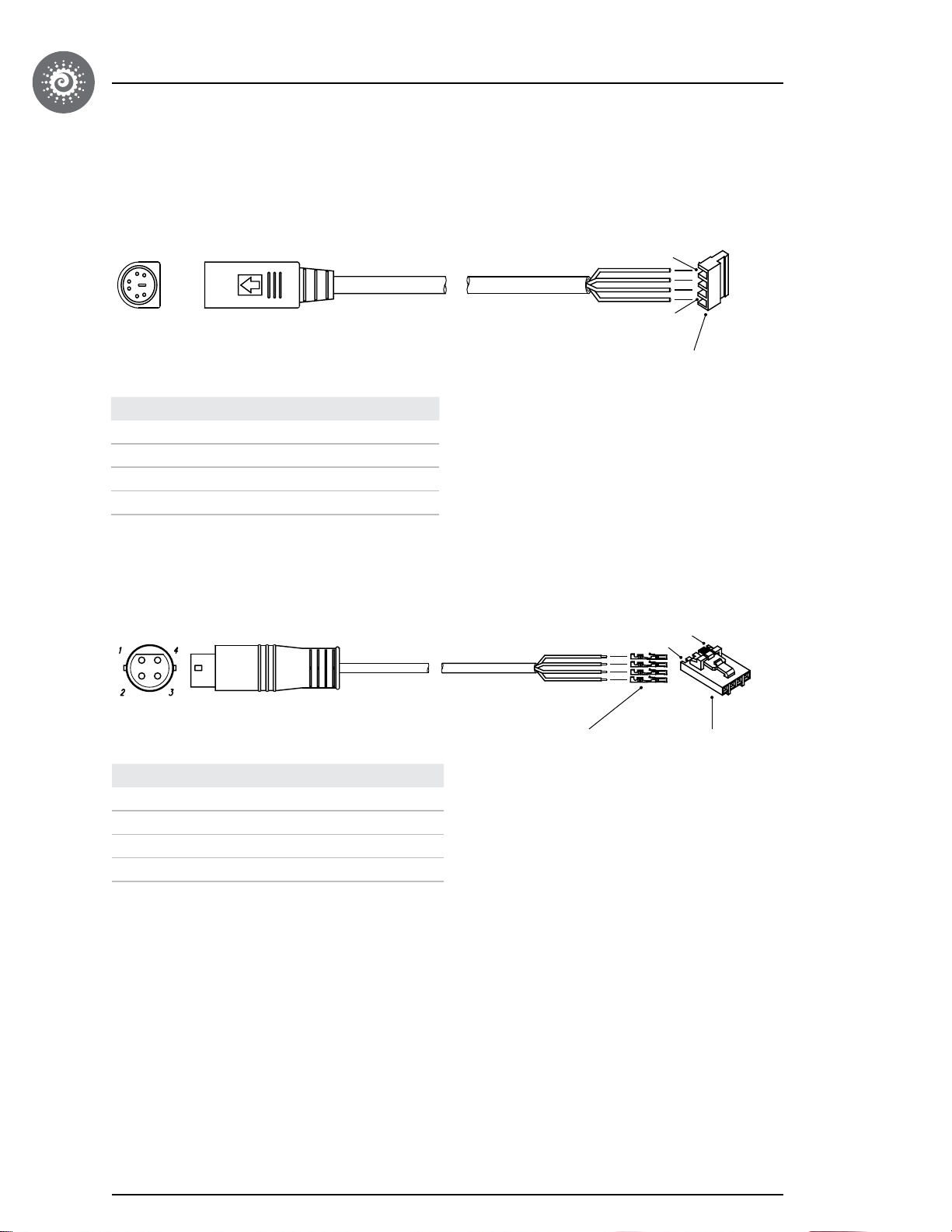
Other compatible LED lights
Rosstech
Pin Function
1 (red) BLUE
2 (green) GREEN
3 (white) RED
4 (black) Vcc
4
1
MTA-100 FEMALE 4 POSITIONS
TYCO P/N: 3-640440-4
Maximum LED Quantity: 100 LEDS
Consumption: 12V
Rising Dragon
Pin Function
1 (blue) BLUE
2 (green) GREEN
3 (red) RED
4 (black) Vcc
1
MOLEX P/N : 16-02-0102 4X
MOLEX P/N: 50-57-9404
Maximum LED Quantity: 120 LEDS
Consumption: 5V
4
12
Page 14
Connections
Other compatible LED lights
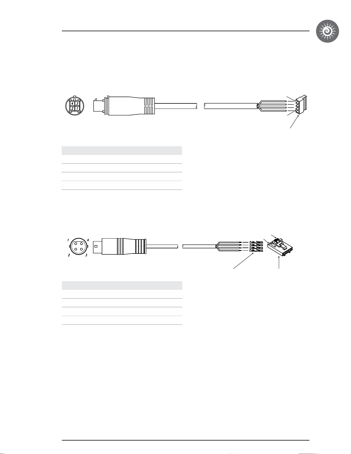
Sloan LED
Pin Function
1 (black) BLUE
2 (white) GREEN
3 (green) RED
4 (red) Vcc
4
1
MTA-100 FEMALE 4 POSITIONS
TYCO P/N: 3-640440-4
Maximum LED Quantity: 120 LEDS
Consumption: 12V
Proway
Pin Function
1 (blue) BLUE
2 (green) GREEN
3 (black) RED
4 (red) Vcc
MOLEX P/N : 16-02-0102 4X
MOLEX P/N: 50-57-9404
Maximum LED Quantity: 120 LEDS
Consumption: 5V
4
1
13
Page 15
Connections
Other connections
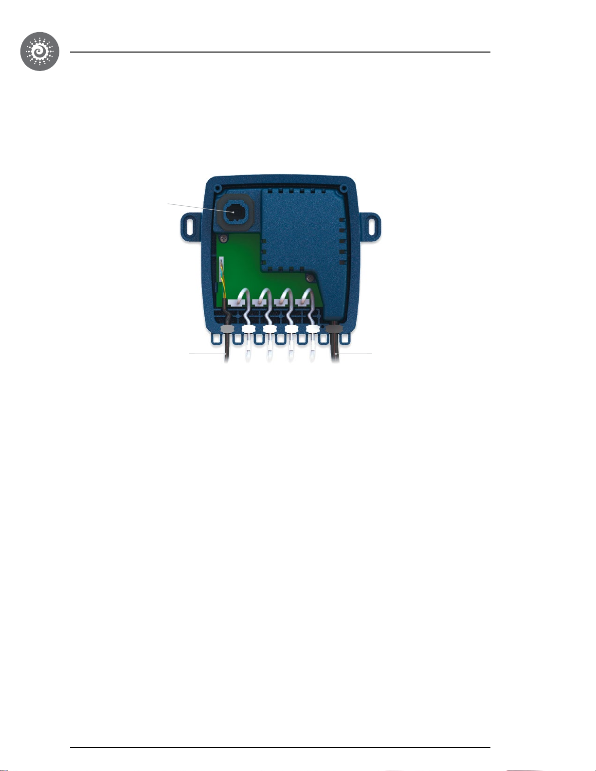
Complete the cabling as follows:
CO on the enclosure to connect
to other accessories
To CO Pack
Connect the CO cable of the in.mix 300 to the CO
connector of the spa pack. See the documentation
related to your specific pack model for more details on
this connection.
AC Power input
Connect the AC power cable of the in.mix 300 to a direct
output of the spa pack. See the documentation related
to your specific pack model for more details on this
connection.
14
Page 16
Compatible keypads
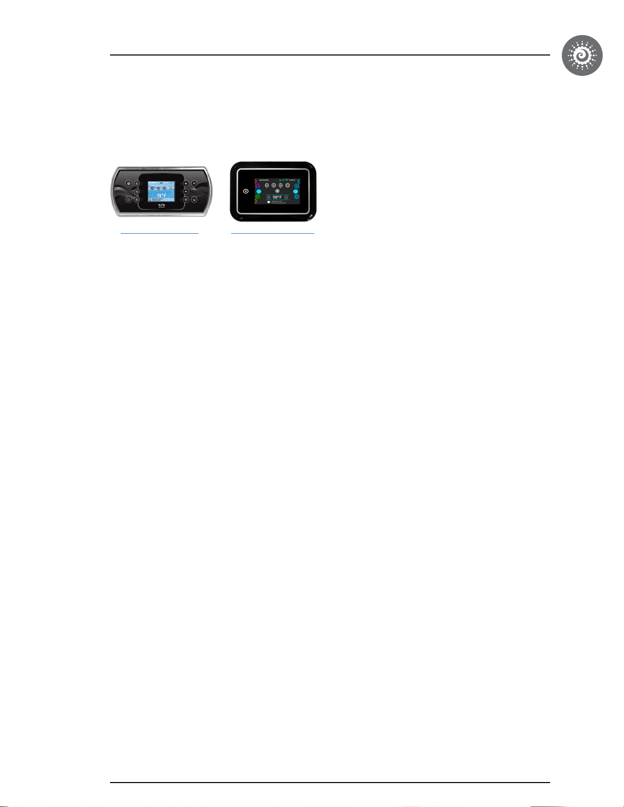
List of keypads compatible with in.mix 300
For more information on the keypads compatible with your in.mix 300 refer to the corresponding techbook.
in.k800 main keypad
Color LCD display, 10 keys
in.k1000 main keypad
Color LCD capacitive
touchscreen display
15
Page 17
Troubleshooting
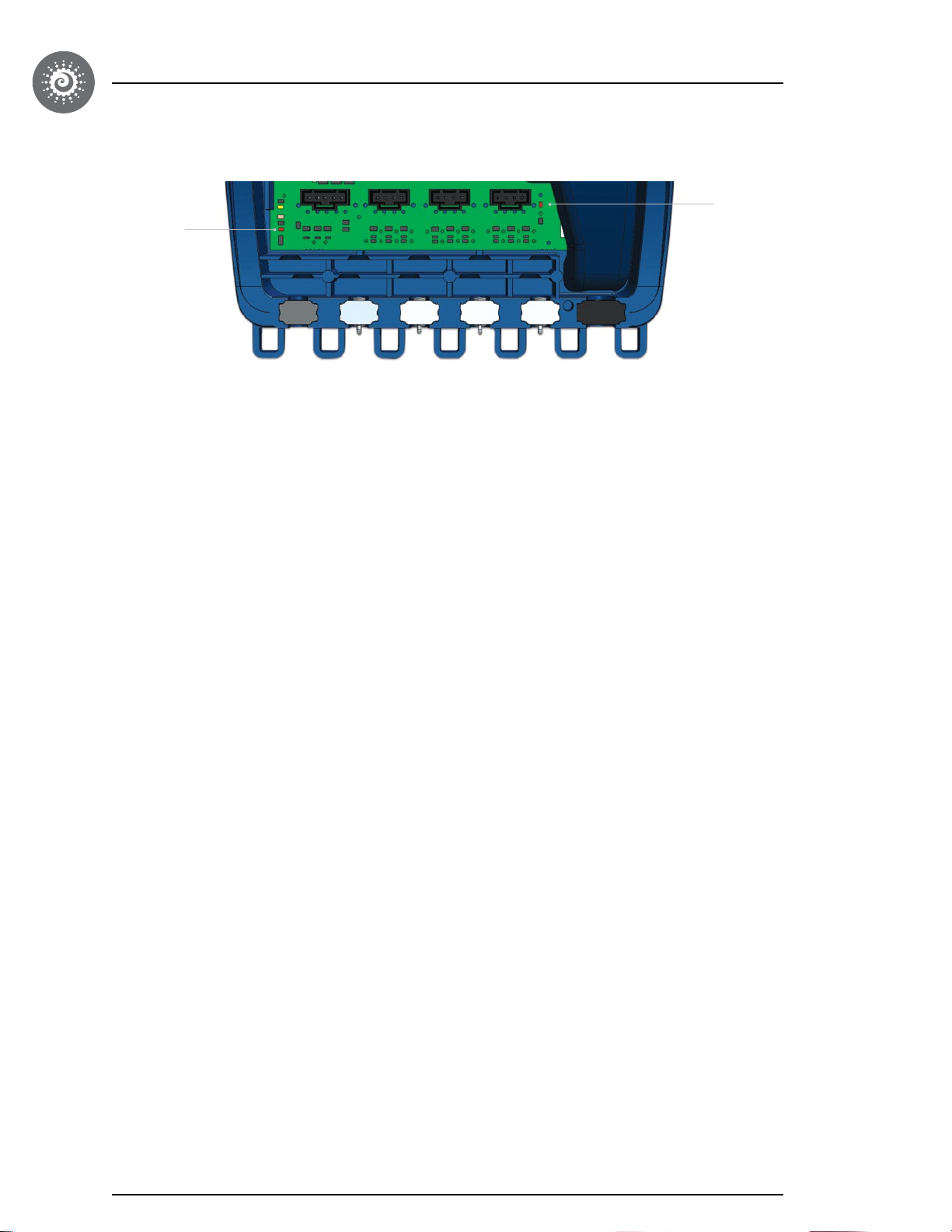
Led Diag #1
LED Diagnostic #1
Led Diag #2
This LED is normally always lit (red). If it is not lit, this indicates a short circuit (or an overload) on the V
power supply.
CC
This unit supplies a maximum of 1.6A.
• Turn off the power of the pack and in.mix 300. Verify the Pack Fuse.
• Unplug all outputs (1 to 4).
Turn on the power of the pack as well as in.mix. If the LED lights up then, there is an issue with one of the Zones
connected to the in.mix 300.
• Plug the Zone connectors back one by one to see which one is causing the problem.
• If none of them seem to be the source of the problem, there is an issue with the in.mix 300. Replace it.
LED Diagnostic #2
This LED is normally always lit (red). If not, check if all cables are connected correctly. If all of the connections are
verified, replace the in.mix 300 pcb.
16
Page 18
Specifications
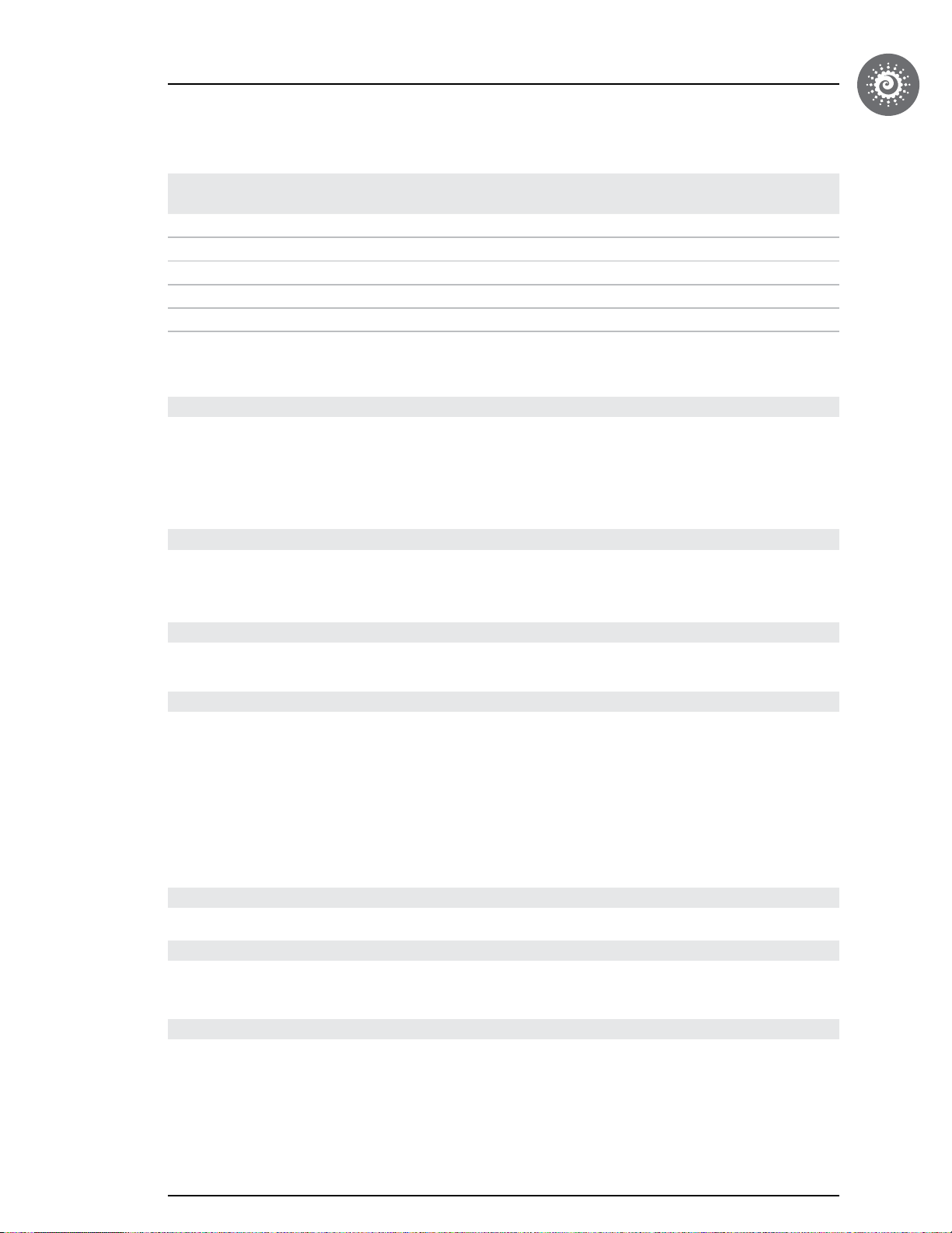
Model number Description
0609-521001 in.mix 300-SL-AMP-V-GE1 • • •
0609-521002 in.mix 300-SL-IN-5V-GE1 • • •
0609-521003 in.mix 300-MTA-AMP-12V-GE1 • • •
0609-521004 in.mix 300-MTA-IN-12V-GE1 • • •
0609-521005 in.mix 300-JJ-IN-5V-GE1 • • •
LED 5VLED
12V
In
Molex
In
MTA100
IN
J&J
Alim
4 pos
Alim
in.link
Environmental ratings
Operating temperature: -4 °F (-20 °C) to 140 °F (60 °C)
Storage temperature: -22 °F (-30 °C) to 185 °F (85 °C)
Humidity: 70% max
Water resistance: IPX5
Mechanical
Weight: 1.9 lb (870 g)
Dimensions (W x H x D): 7.03'' x 6.13'' x 2.22'' (179 x 156 x 56 mm)
Line input
Input voltage: 100-240VAC 50/60 Hz
LED outputs
Other connections
Compatibility
UL & CSA certifications
5 VDC or 12 VDC output, variable
3 Independent zones
4 Connector outputs, can be assigned by low level configuration to
any of the zones
up to 100 points of light (RGB)
up to 78,000 colors *
2 Rainbow effects with smooth transition
plug and play with J&J light spider and cluster
Additional CO connector for the other accessories
Compatible with X and Y series version 2 (-V2)
Compatible with in.k800 version 22 or in.k1000 version 14
UL1563 sixth ed.
UL file: E182156
CSA No. 22.2 - 218.1 - M89
* With in.k1000 keypad only. The in.k800 keypad offers a selection of 10 colors.
17
Page 19

Specifications
European certifications
CEM Europe
EN/IEC60335-1: 2010/A1: 2013
EN/IEC60335-2: 60/A2: 2008
CSA No. 22.2 - 218.1 - M89
EN 55014-1
EN 55014-2
EN 61000-3-2
EN 61000-3-3
18
Page 20

9919-101516-C
Rev. 08-2017
© Groupe Gecko Alliance inc., 2017
All trademarks or registered trademarks
are the property of their respective owners.
450 des Canetons, Québec (Qc), G2E 5W6 Canada, 1.800.78.GECKO
Gecko Alliance
www.geckoalliance.com
Printed in Canada
 Loading...