


Gecko
141 Palmer Street, Richmond VIC 3121 Australia T:+61 3 8420 8940 sales@src.com.au
For all models: Compact, Rugged, Blast, Tremor, Prism, SMA & SMA-HR
Seismographs, Accelerographs
Recorders, Vibration Monitors

Welcome to the world of simplified seismic recording with your new Kelunji Gecko
seismograph. Within minutes you can be recording earthquakes, blasts and other ground
vibrations using our latest generation instrument that takes high dynamic range, high
sample rate, low power, continuous recording into new territory.
In the Gecko, we have reinvented the modern digital seismograph. The low cost of flash
memory means you can save weeks, months, even years of continuous data on a single
memory card. The Gecko can record everything continuously while logging trigger times for
you to sort through back at the lab. Even if your trigger settings missed the event, you’ll
always be able to retrieve that chunk of time from the continuous archive.
An even more efficient way of managing your data is not to have to collect it at all, so we
have included a simple telemetry protocol that streams data packets over the Internet via a
cellular data modem or Ethernet link. Data from all of your stations is then available in a
single archive for you to access whenever you need it. Simply install our free “Live Stream”
data reception software on your Windows, Mac or Linux PC and watch your data live on
screen while it is archived away to your PC. Live Stream is ideal for collating data from
multiple network-connected structural monitoring instruments. Download it free today from
the SRC website: https://www.src.com.au/downloads/live-stream/
Our “Waves” waveform analysis application is available as a free download for Windows,
Mac and Linux from http://www.src.com.au/downloads/waves/ . Each Gecko purchased is
entitled to one Waves product key that will remove the advertisement that pops up for 10
seconds when you launch the program. Simply email sales@src.com.au with your recorder
serial number to obtain a product key. Each product key can only be used once and is not
transferable to another computer.
Happy recording!
From the Gecko development team.

Table of Contents
Getting Started ................................................................................. 1
Setting up your recorder ..................................................................................... 1
The User Interface .............................................................................................. 2
Menu Map ............................................................................................................ 3
The Home Screen .............................................................................. 4
Status Screen Loop – Right Button ...................................................................... 4
Realtime Data Loop – Up Button .......................................................................... 5
Sensor Signal .................................................................................................... 5
Vector Sum ....................................................................................................... 5
Raw Signal ........................................................................................................ 5
The Main Menu .................................................................................. 6
Unmount SD card ................................................................................................ 6
Data Storage ..................................................................................................... 7
Station Info ......................................................................................................... 7
Station Code ..................................................................................................... 8
Network Code .................................................................................................... 8
Location ID ....................................................................................................... 8
Sample Rate ........................................................................................................ 9
Channels to Store .............................................................................................. 10
Channels to Send .............................................................................................. 10
Sensor Setup ..................................................................................................... 10
3D Sensor ....................................................................................................... 10
External 1D Sensor .......................................................................................... 13
Input Amplifier .................................................................................................. 14
Trigger & Alarm ................................................................................................. 15
Level Triggering ............................................................................................... 15
STA/LTA Triggering .......................................................................................... 16
Alarm Outputs ................................................................................................. 17
System Alerts .................................................................................................. 17
On-screen Alerts .............................................................................................. 18
Telemetry .......................................................................................................... 18
Mode .............................................................................................................. 19
Device ............................................................................................................ 19
3G modem Settings .......................................................................................... 19
Settings File ...................................................................................................... 20
Start Calibration ................................................................................................ 20

Data Storage and Formats .............................................................. 21
The Root Directory ........................................................................................... 22
The Data Folder ............................................................................................... 22
The Histogram Folder ....................................................................................... 23
MiniSEED files ................................................................................................... 23
Upgrading the Gecko firmware .......................................................................... 24
Ports & Wiring ................................................................................ 24
Power connector ............................................................................................... 24
Alarm & Communications port ........................................................................... 25
4D Sensor port (2018 Compact & Rugged) ........................................................ 25
1D Sensor port (mid-2019 Blast & SMA) ........................................................... 25
Register your Gecko ........................................................................ 26
Warranty ........................................................................................ 26
Extended warranty ............................................................................................ 26
Appendix A ..................................................................................... 28
Installing the Gecko Blast or SMA ..................................................................... 28
Gains, range and clip levels ............................................................................... 29
Installing the Gecko SMA-HR ............................................................................ 30
Calibrating a Gecko SMA-HR .............................................................................. 32
Installing the Gecko Tremor .............................................................................. 32
Installing the Gecko Prism ................................................................................ 33
Checking Sensor Operation ................................................................................ 33
Appendix B ..................................................................................... 34
Internal Battery ................................................................................................ 34
Charge Regulator .............................................................................................. 35
LED Patterns (routine) ...................................................................................... 35
LED Patterns (exceptions) ................................................................................. 35
Appendix C ..................................................................................... 36
Perle IOLAN DS1 Ethernet Adaptor ................................................................... 36
Change IP address of the Ethernet adaptor ....................................................... 37
Define IP address of Kelunji Hub computer ....................................................... 38

1
Getting Started
All Gecko models have a 2-pin power port, 6-pin alarm/communications port, and a coaxial
GPS aerial connection. From mid 2019 Gecko Blast & SMA models also have a 4-pin port for
an external sensor channel. Gecko Compact & Rugged have a 19-pin sensor connection.
Setting up your recorder
The two-pin connector is the power input to the Gecko. The default Gecko operating voltage
range is 11.5 and 24 Volts DC (useful for 12V DC battery over-discharge protection), but it
can be factory switched to extend the range to 7V to 30V DC at no cost. If the power is
removed then restored, the Gecko will restart using the saved settings.
The Gecko only takes a few seconds to initialise the operating system after power is applied.
If an SD card is installed, the recorder will start storing continuous data to the SD card
within seconds.
The small gold coaxial socket is the connection for the GPS aerial. The GPS is crucial in
maintaining accurate absolute time to synchronise recordings from various instruments and
monitoring locations, but it also provides global position information. Simply screw the GPS
cable plug onto the threaded GPS socket until finger-tight.
The Gecko Compact and Rugged is supplied with a sensor plug which you can attach to your
sensor cable. You can find the wiring diagram at the end of this manual. Align the keyed
plug with the socket and push it on, locking it in place with the bayonet-style collar.
At this point you now have a fully functioning recorder, but you will need to modify some
settings to suit your application. Setting a unique station code is an essential starting point.

2
The User Interface
The Gecko does not require a computer to control it. All recorder settings are accessible
through the LCD and are modified using the four control buttons.
Gecko Compact (above)
Gecko Rugged; and Gecko Prism, Tremor & Blast velocity sensors (above)
Gecko SMA, SMA-HR, and Prism acceleration sensors (above)
SEISMOGRAPH
RIGHT
MENU
(LEFT)
UP DOWN
ACCELEROGRAPH
RIGHT
MENU
(LEFT)
UP DOWN

3
Menu Map
After start-up, pressing the Menu button will toggle between the main menu and the home
screen. The LCD backlight will stay on for 2 minutes from the last button press.
On most screens you can scroll Up and Down through a list and enter a menu item or
toggle a setting by using the Right button. Pressing the Menu button will save the current
setting and take you back one menu level.
E: -2,726 0.6
N: 4,326 0.8
Z: -698 0.7
O: 12,356 1.2
*1
p
3D 0.1234567 mm/s
max 11.1234567 mm/s
1D 80.2123546 dB
*1
max 101.1234567 dB
*1
p
2019-04-01 11:52:18
E: -0.0439408 mm/s
N: 0.0360011 mm/s
Z: -0.0011021 mm/s
p
Home Screen
Info & Telemetr y 3D Sensor Info GPS loca tion information
2019-04-01 11:52:16 Volt: 14.06 500sps
3D Sensor Name & S/N
*2
Lat: -37.8189800
GECKO Storing ENZO+
u
Temp: 35.5° x512uGecko Blast
u
Long: 145.0109620
GPS:04 Sending ___O+ #2000343 v4.2.4271 586-H2 586-H1 586-V3 Sats: 12 Alt: 22m
32GB free:92.23495% Connected to Server Type: Acceleration hAcc: 10m vAcc: 19m
Main Menu Station Information Save Continuous Data 3D Sensor
Unmount SD card Station Code Channel E: On Sensor Name
> Station Info > Network Code Channel N: On > Units
Sample Rate Location ID (3D) Channel Z: On Sensitivity ch E
Channels to Store Location ID (1D)
*1
Channel O: On
*1
Sensitivity ch N
*5
Channels to Send 3D Vector: Off Sensitivity ch Z
*5
3D Sensor
*3
3D Sensor
Auto-Zero Delay
*5
1D Sensor
*1
Select a Sensor
Cal Enable
*5
Input Amplifier > Select a Sensor Custom Sensor Cal Type
*5
Trigger & Alarm Sensor Serial No > Geophone 28.8V/m/s Cal Duration
*5
Telemetry Mass Lock
*5
Geospace GS-1 1Hz Cal Sine Freq
*5
Settings File Mass Unlock
*5
...<more> SIG+ Mode: Normal
*5
Start Calibration
*4 *5
SIG- Mode: Normal
*5
Input: DC Offset
*5
Communications STA/LTA Triggering
Trigger & Alarm
Enable: Off
Level Triggering
> Mode: Continuous > Threshold
Device: 3G modem > Level STA window size > Enable: Off
TCP Socket Port
*6
STA/LTA LTA window size Set Trigger Level
Server IP/Domain
*6
Alarm Outputs Filter: 2-20Hz
Carrier APN
*6
System Alerts Channel: Z+N+E
Raw Values
Vector Peak
Sensor Signal
Gecko menu appearance will vary by model:
*1 will not appear on 3-channel models
*2 "1D Sensor Info" will show here for 4-channel models
*3 will only appear on Gecko Compact & Rugged
*4 will only appear if sensor has calibration function
*5 will not appear when setting up 4th channel
*6 will only appear for 3G modem on menu re-entry

4
The Home Screen
The home screen shows:
• the Gecko clock’s date and time (in UTC – Universal Time Coordinated)
• station code, and which channels are being stored to the SD card
• number of GPS satellites visible; and channels being sent via Telemetry
• SD card capacity and percentage of storage remaining
2019-04-01 05:52:16
GECKO Storing ENZO+
GPS:04 Sending ___O+
32GB free:92.23495%
“O” is the 4th channel on some Gecko models, and “+” is the vector sum of channels ENZ.
The “Storing” word animates using q down arrows to indicates packets of data for the
displayed channels are being written to the SD card. The “Sending” word animates using p
up arrows to indicate packets of data for the displayed channels are being streamed to a
remote computer.
Status Screen Loop – Right Button
Version 4 of the Gecko firmware expands the status line to several status pages. These are
shown on the Menu Map within the blue area. Press the Right button to scroll through
them, or press the Menu/Left button to return to the Home screen.
• The first screen shows input power voltage and CPU temperature, the current sample
rate and input amplifier (gain) setting, followed by the Gecko serial number and
firmware version number. The firmware version now integrates the “build” number.
If telemetry is enabled, the bottom line shows the connection status
• The next screen shows the name and serial number of the 3D sensor connected to
channels ENZ. The sensor type is shown on the bottom line
• If you have a 4-channel recorder, the next screen shows the 1D sensor information
• The final screen shows the GPS location information. The “hAcc” value is the
horizontal accuracy value of the GPS aerial position in metres as read from the GPS
receiver, and “vAcc” is the vertical accuracy.
Home Screen
Info & Telemetry 3D Sensor Info GPS location infor mation
2019-04-01 11:52:16 Volt: 14.06 500sps
3D Sensor Name & S/N
*2
Lat: -37.8189800
GECKO Storing ENZO+
u
Temp: 35.5° x512uGecko Blast
u
Long: 145.0109620
GPS:04 Sending ___O+ #2000343 v4.0.4234 586-H2 586-H1 586-V3 Sats: 12 Alt: 22m
32GB free:92.23495% Connection Status Type: Acceleration hAcc: 10m vAcc: 19m

5
Realtime Data Loop – Up Button
Press the Up button from the Home screen to view real time sensor data.
Sensor Signal
The first screen shows sensor output in real units in real time. These values are calculated
based on the sensor and gain settings. Tap or shake the sensor to see the numbers change.
Pressing the Right button on this screen will prompt you to
press the Right button again to reset the zero level. The
Zero Level is set based on the average signal level over the
next 2 seconds.
If you have a 4-channel Gecko, the date and time line will not be shown, with channel O
appearing at the bottom with its live sensor units values shown as per the settings.
Vector Sum
The next screen Up shows the live vector sum of the 3D sensor, and holds the peak value.
For 4-channel models, the live data from channel O is shown and its peak (max) value held.
Pressing the Right button on this screen will prompt you to
press the Right button again to clear the peak values.
Raw Signal
Pressing Up again will display the raw numbers from the ADC in real time. The values
shown are up to ±8,388,608 counts, which represents a signed 24-bit number.
Pressing the Right button will prompt you to do so again to
confirm a reset of the zero level. If you have a 4-channel
Gecko, the date and time line will not be shown, with
channel O appearing at the bottom.
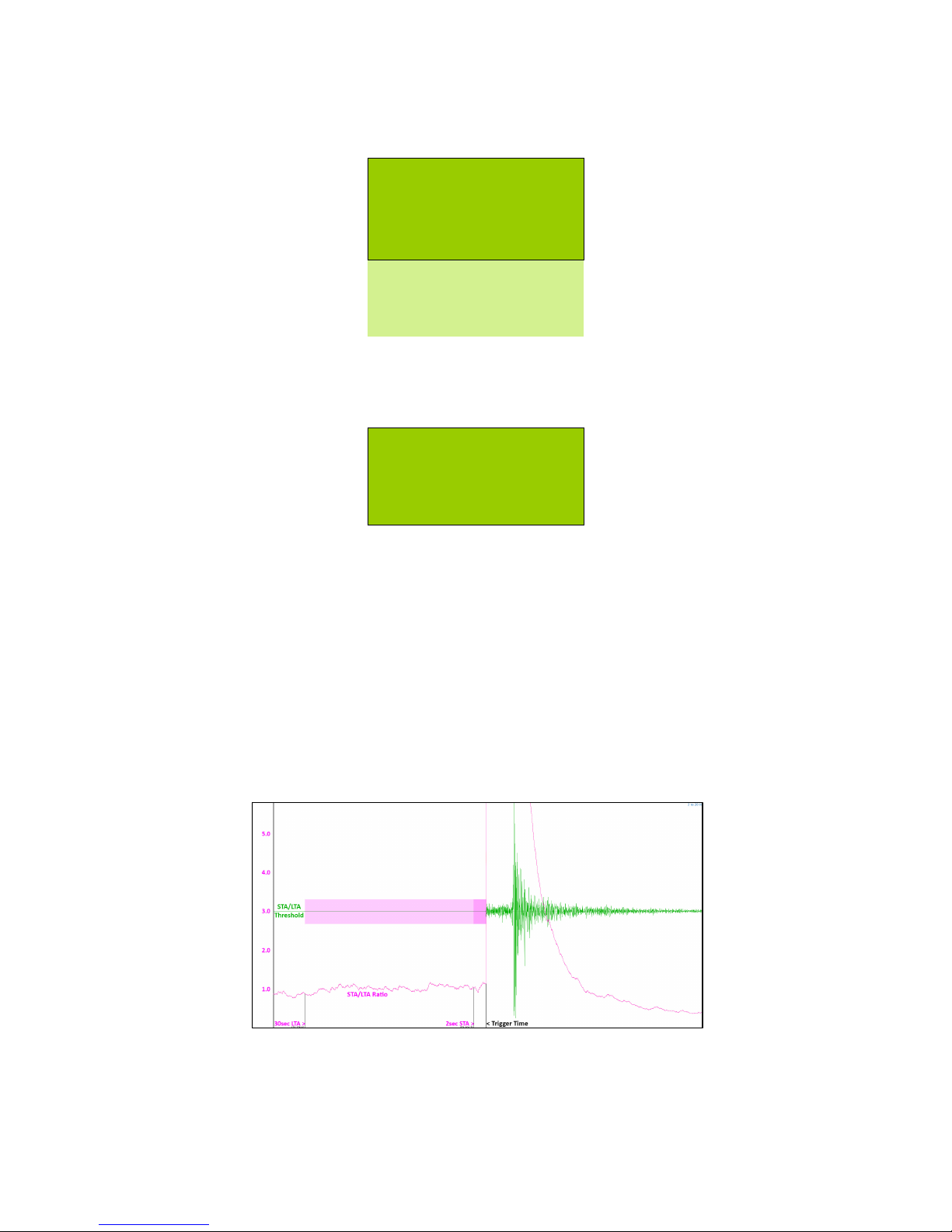
Another feature of this screen is the ability to view the STA/LTA ratio in real time. The value
at the end of each line is the ratio of the average signal in the short term divided by the
average signal in the long term. When nothing much is happening, this value will sit around
1.0, but a short burst of anomalous signal will increase number. This number may assist
you in determining at what level to set your STA/LTA trigger threshold.
Note: The STA/LTA value will only display if STA/LTA triggering is enabled.
2019-04-01 11:52:18
E: -0.0439408 mm/s
N: 0.0360011 mm/s
Z: -0.0011021 mm/s
3D 0.1234567 mm/s
max 11.1234567 mm/s
1D 80.0360011 dB
max 101.0011021 dB
2019-04-01 11:52:20
E: -2,726 0.6
N: 4,326 0.8
Z: -356 1.2

6
The Main Menu
Pressing the Menu button from the home screen will show you a list of actions and settings
for managing your recorder. The main menu includes some or all of the following items:
Main Menu
Unmount SD card
> Station Info
Sample Rate
Channels to Store
Channels to Send
3D sensor
1D sensor
Input Amplifier
Trigger & Alarm
Telemetry
Settings File
Start Calibration
If you change any settings, they are applied once you exit to the home screen. The settings
are also automatically saved to the recorder’s configuration file.
Unmount SD card
In version 3.2 of the Gecko firmware we removed the option to stop and start data
sampling. Data is being sampled at all times, whether an SD card is present or not, because
data can be telemetered without an SD card. If there is no SD card, backfilling of unsent
data will not be possible.
Before you remove the SD card, you should unmount the SD card so that the system does
not try to write data to the SD card while it is being removed, an action that can corrupt the
file, file system, or SD card.
When you insert an SD card, it will automatically be mounted.

7
Data Storage
The Gecko is supplied with a 32GB SD card, formatted with the FAT file system. Larger
capacity SD cards can be used in the Gecko if they are pre-formatted as FAT (not exFAT).
To remove the card from a Gecko Compact 3ch (above, left) slide open the SD card cover
and press in the SD card to eject it. The SD card faces up, and it cannot be inserted upside-
down. For the Gecko Compact 4ch (above, centre), the SD card cover requires a quarter
turn anti-clockwise before removal. The SD card faces the rear of the recorder.
If you have a Rugged model with optional integrated sensor, unscrew the card cover to
access the SD card slot (above, right). The SD card faces the rear of the recorder.
Insert the SD card into your computer (directly if you have an SD card slot, or via a USB
card reader) and you’ll be able to browse your continuous data files.
To re-insert the card, push the SD card into the socket, ensuring you feel the card spring
back from push-lock. The SD card will automatically mount and recording should resume.
Check that the q arrows are animating over the word “Storing” on the Home screen, which
indicates data packets are being written “down” to the SD card.
Station Info
Every seismic monitoring point needs to have a unique identifier. As part of the MiniSEED
data format standard there are three tiers of identifier – Network, Station, and Location.
Station Information
Station Code
> Network Code
Location ID (3D)
Location ID (1D)

8
Station Code
Important! Please change your station code to a unique code, otherwise data
from all of your stations will be called GECKO and it will be difficult for
you to work out which data files came from which station!
The station code identifies the location of the station. If a location has multiple sensors (e.g.
monitoring a building, or setting up an array of sensors) you can use the same station code
but identify each recording point with a different Location ID.
This station code (default is GECKO) can be up to 5 characters long and can only contain
uppercase letters and numbers. If you wish to use less than 5 characters, end the code with
blank space character. Note that any characters after a blank space will be ignored (e.g. if
you enter “ABC 1” the Gecko will use station code “ABC”).
Enter Station Code
GECKO
A flashing block indicates the cursor position. Use the Up and Down buttons to scroll
through letters and numbers, and use the Right button to move to the next character.
Press the Left/Menu button when on the first character to save and exit.
Network Code
The MiniSEED format allows you to include a two character network code, which can be your
FDSN code. For example, the Seismology Research Centre uses “OZ”, Geoscience Australia
uses “AU”, and the British Geological Survey uses “GB”. You can register for an FDSN code
at fdsn.org, or you can use this field for you own identification purposes.
Location ID
As mentioned above, a seismic monitoring station may have multiple monitoring points, so
rather than coming up with a station code for each, they can all use the same station code
with a unique Location ID. This field is any two character code. For example, if you are
monitoring the basement, middle and top of a building you could use Location IDs of B1,
M1, and T1; or simply 01, 02 and 03.
The default value for channels ENZ is 00, and for 4-channel systems channel O has ID 01.

9
Sample Rate
Some sample rates in the Gecko use an FIR filter to remove
frequencies above the Nyquist frequency, i.e. half the
sample rate, e.g. 50Hz at 100 samples per second (sps).
250, 500, 1000, 2000 and 4000sps do not use FIR filtering.
Scroll to the sample rate you wish to use, then press the
Menu button to exit and apply the new sample rate.
Channel Naming
The naming of channels has been automated in the Gecko based on the selected sample
rate and sensor type, with preset channel names.
The SEED standard states that each channel requires a 3-letter code, where the first letter
indicates the Band Code, the second letter indicates the Instrument Code, and the third
letter is the Orientation Code. Detailed information on this standard can be found here:
https://ds.iris.edu/ds/nodes/dmc/data/formats/seed-channel-naming/
The Gecko will set the first letter of the channel name based on the sample rate:
• B: 40 sps
• H: 100 & 200 sps
• C: 250, 400, 500, 800 sps
• F: 1000, 1600, 2000, 4000 sps
The Gecko will set the second letter of the channel name based on the sensor type:
• H: Velocity Seismometer
• N: Accelerometer
• D: Pressure Sensor (e.g. Microphone)
• J: Rotation Sensor
• Q: Voltage
The Gecko will set the third letter of the channel name based on the channel number:
• E: channel 1, typically used for East, Transverse, or X
• N: channel 2, typically used for North, Radial, or Y
• Z: channel 3, typically used for Up, Vertical, or Z
• O: channel 4, typically used for Outdoor Microphone or an extra Vertical sensor
For example, the vertical channel of 40sps broadband seismograph would be BHZ, whereas
a horizontal channel of a 100sps structural monitoring accelerograph might be HNE or HNN.
The data stored as the vector sum of the 3D sensor is named SUM and will use the same
location ID as channels E, N, and Z to reinforce the association with those channels.
Select Sample Rate
40 sps
> 100 sps
200 sps
250 sps
...<more>

10
Channels to Store
As of firmware version 4.0, the Gecko can now turn off any unused channels to save
storage space, and can store (and send) the vector sum of the 3D channels.
Toggle the channels on or off as required. The 3D Vector
channel is the vector sum of channels ENZ, which can now
be stored and streamed. Note that if a channel is enabled for
telemetry (see next setting below), it will automatically be
stored to the SD card as well to ensure the data is available
for backfill should the communication link drop out.
If all channels are accidentally turned off, the Z channel is automatically re-enabled to
ensure at least one channel is being recorded. Note that if a channel is turned off here, it
will also be turned off in the “Channels to Send” settings – see below.
Channels to Send
You can select which channels to send continuously to your remote server. For vibration
monitoring applications you may choose to send the 3D Vector sum channel continuously,
storing the ENZO channels to be sent if a trigger process is enabled and an event detected.
Toggle the channels on or off as required using the Right
button. Version 4 of the Gecko now allows you to stream the
Vector Sum of channels ENZ instead of the individual
channels, although these channels can still be stored and
telemetered when the Gecko triggers.
Note that if a channel is enabled for telemetry, it will
automatically be turned on in the “Channels to Store” settings as the stored data is required
for backfilling gaps in data telemetry. Disabling a channel in telemetry will not disable that
channel in the “Channels to Store” settings.
Sensor Setup
This section of the user manual applies to Gecko Compact, Rugged, Blast and SMA models only. For all
other models, skip ahead to the Input Amplifier section.
3D Sensor
This menu has items that deal with 3D sensor information
and control. This will not be visible in the Blast or SMA, but
the method same applies for setting up the 1D sensor, so
Blast & SMA users should read this section.
Save Continuous Data
Channel E: On
> Channel N: On
Channel Z: On
Channel O: On
3D Vector: Off
Send Continuous Data
Channel E: Off
> Channel N: Off
Channel Z: On
Channel O: Off
3D Vector: Off
3D Sensor
> Select a Sensor
Sensor Serial No.
Mass Lock
Mass Unlock

11
Select a Sensor
The Gecko has a range of popular sensors settings preloaded into the menu to save users
the trouble of entering all of the parameters that allow the data to be displayed in
engineering units (e.g. mm/s, g, mm, dB, rad/s, etc.) rather than recorder counts.
Select a Sensor
Custom
> Geophone 28.8V/m/s
Geospace GS-1 1Hz
…<more>
Scroll down to the sensor you have connected and press the Menu/Left button to exit and
save. This will copy the selected sensor values to the “Custom” sensor so that you can
adjust the settings for your particular sensor. To do this, re-enter the “Select a Sensor”
menu and scroll up to “Custom” and press the Right button to edit the parameters.
Custom Sensor
If you are connecting a sensor that is not in the predefined list, start from a similar type of
sensor and customise the parameters to match your sensor so that the data is stored with
the basic corrections that can be applied automatically when viewed in Waves.
3D Sensor
Sensor Name
> Type: Velocity
Sensitivity ch E
Sensitivity ch N
Sensitivity ch Z
Auto-Zero Delay
Cal Enable
Cal Type
Cal Duration
Cal Sine Freq
SIG+ Mode: Normal
SIG- Mode: Normal
Input: DC Offset
If a setting has a colon, press the Right button to toggle its value, otherwise Right will
enter a menu to select a setting from a list. In the latter case, edit the parameter using the
Up and Down buttons, and use the Menu/Left button to save and exit.
The Sensor Name is a free text field to help you identify the model you are creating. This
can be up to 20 characters long.

12
The Type of sensor you are using can be toggled between Velocity (where units are defined
in metres per second), Acceleration (g), Pressure (pascal), Rotation (radians per second),
Displacement (metres), and Other (“units”).
Sensitivity can be set per channel, which indicates how many Volts-per-unit your sensor
outputs, e.g. 750V/m/s for a Nanometrics Trillium Compact velocity sensor. Note that
Acceleration units will be saved as V/m/s2 in accordance with international standards, but
entered as V/g for convenience as most sensors are specified in this manner.
The Gecko can automatically set the zero signal level after the recorder is powered up. If
your sensor performs a self-test on start-up, or requires some time before it settles, use the
Auto-Zero Delay to define the number of seconds to wait until the start of the zero-level
determination process (a 2-second average) or set the value to zero to disable the signal
zeroing function.
Some sensors have a calibration circuit whereby the recorder can send it a stepped voltage
or sine wave signal, and the components will respond accordingly to show that they are
working as expected. Some sensors require a control signal to tell it to enter calibration
mode – the type of control signal is set under the Cal Enable menu.
The Cal Type defines the type and amplitude of the signal size that is sent to the sensor.
There are four sizes of step voltages and sine waves: small, medium, large and extra large,
which generate amplitudes of about 0.5V, 1V, 5V, 10V respectively.
The Cal Duration is the number of seconds that the sine or step signal is active, which is
normally set to the long period response time of your broad band seismometer, or just a
few seconds for a short period seismometer or accelerometer. A “Step” calibrate will run for
twice the entered value to capture the trailing edge of the step response.
The frequency of the sine wave can also be set in the Cal Sine Freq menu, with available
choices being 1Hz, 5Hz, 10Hz, 50Hz, 100Hz, 500Hz, and 1000Hz.
Previously know as “Input Mode” the SIG+ Mode setting tells the Gecko how whether or
not power needs to be applied to the sensor channel positive wires (pins C, E, G and S on
the Gecko sensor connector). For most sensors, this mode should be set to “Normal”, but if
you are using an IEPE sensor, you can select “25V” which will put a 25V of DC power at
4mA out to the sensor channel.
WARNING! Enabling 25V output to non-IEPE sensors may damage your sensor
Previously known as “Sensor Wiring” the SIG- Mode tells the Gecko whether the sensor
channel negative wires (pins D, F, H & T on the sensor connector) need to be connected to
power ground or not. Most sensors require you to measure the difference between the
positive and negative wires, so the “Normal” setting would be used in most cases. If your
sensor requires the negative channel wire to be connected to power ground (e.g. for IEPE
sensors) then select “Ground”.

13
An new setting introduced in firmware version 4.1 allows manual control of a high pass filter
on the sensor input. This enables a simple circuit that removes the DC offset from sensors
by introducing a low order high pass frequency filter. For most sensors, it is best to leave
this Input setting as “DC Offset”, but if you are using an IEPE sensor or have a sensor that
has a large DC offset, set the Input to “Filtered” to enable the filter which will slowly bring
the signal level down to zero. Do not enable this for long period or broadband
seismometers.
An example of where this Input Filter is important is with the White Industrial Geophones,
which have a signal output between 0V to +5V, where the zero level normally sits at +2.5V.
In this case, much of the -20V to +20V input range of the Gecko is wasted. Running the
Gecko’s Input Amplifier at x4 would effectively stretch the 0-5V to 0-20V, but you would
still only be using the upper half of the Gecko’s dynamic range. By enabling the Input Filter,
the zero level of 2.5V would be brought down to 0V, so the output signal would be -2.5V to
+2.5V. This allows you to use an Input Amplifier setting of x8 to stretch the sensor’s output
from -20V to +20V, using the full dynamic range of the Gecko’s 24-bit resolution.
Sensor Serial No.
A 20-character field is available to record your sensor’s serial number. This information is
stored in the station status text file for future reference. Upper and lower case letters,
numbers, and some special characters are available.
Mass Lock & Unlock
Guralp 3-series seismometers have motorised mass controllers that allow the delicate
sensor components to be locked in place for transport and unlocked after installation. Use
Sensor Lock before moving a sensor (this takes just a few seconds), or Sensor Unlock
when the sensor is in place and ready to start monitoring, or to re-centre the masses.
Issuing this command simply connects one of two pins on the sensor connector to Ground
for 5 seconds, so the feature could be used for other purposes if required.
External 1D Sensor
If you have a 4-channel Gecko Compact, Rugged, Blast or SMA, you can set up your 1D
sensor in a similar way to the 3D sensor. Simply select a sensor from the list and optionally
re-enter the menu to customise its name, units and sensitivity. No other settings are
available for this channel.
1D Sensor
Sensor Name
> Type: Pressure
Sensitivity
Set the sensor serial number using the only other menu option.
The SIG+, SIG- & Input settings of the 1D sensor are the same as set for the 3D sensor.

14
Input Amplifier
The Gecko is, fundamentally, a high speed, high resolution Voltage data logger. It measures
the voltage across each channel’s pair of wires, and it can measure from -20V to +20V DC
at 24-bit resolution. This 40V peak-to-peak range is read as a 24-bit number, producing a
value between 0 and 16,777,216 counts, which equates to 419,430.4 counts per volt.
Input Range
x1 (40Vpp)
> x2 (20Vpp)
x4 (10Vpp)
x8 (5Vpp)
x16 (2.5Vpp)
x32 (1.25Vpp)
x64 (625mVpp)
x128 (313mVpp)
x256 (156mVpp)
x512 ( 78mVpp)
If you are using a sensor with a 40Vpp output (for ±10V differential output sensors, such as
Nanometrics or Guralp seismometers) set the gain to x1.
If you have lower voltage output sensors, use the input amplifier to utilise the full dynamic
range of the Gecko - e.g. ±5V IEPE accelerometers or ±4V MEMS accelerometers (as used
in the Gecko SMA), could use a gain of x4 to stretch those output to ±20V or ±16V
respectively to record at higher resolution. Note that ground offsets will also be amplified.
If you are using a passive sensor (e.g. geophone) you can use even higher gains to see
smaller signals at higher resolution. For example, the Gecko Tremor’s geophones (standard
sensitivity of 78.74 V/m/s) normally have a clip level of 254mm/s, but by using a gain of
x16 you can see smaller signals and get a similar effective sensitivity (1260 V/m/s) and clip
level (16mm/s) as a typical short period active seismometer.

15
Trigger & Alarm
The primary function of the Gecko is as a continuous data recorder, but we realise that
triggering is still required to help find events of interest and to control alarms. The Gecko
has two Level trigger processes and an STA/LTA trigger process that can be enabled and
disabled. The Gecko also monitors some system parameters that can generate an alarm.
Trigger & Alarm
> Level
STA/LTA
Alarm Outputs
System Alerts
The Gecko logs the trigger time to a text file that can be used to help you find the data in
the continuous archive. This “trig.txt” file is located in the top level folder of the SD card.
We have developed a small application that can be copied to the Gecko SD card and run
from a Windows computer that will scan the trig.txt folder and then automatically extract
the continuous data from the archive, creating a discreet file in a folder called “reports” on
the SD card that contains one minute of data before and after the trigger time. At the same
time a PDF report is generated for the triggered event, with files named based on the local
time in your PC. This app simplifies vibration monitoring reporting for non-technical users.
Level Triggering
By default each Level trigger process is OFF, but simply toggle this using the Right button.
Level Triggering
> Enable: On
Set Trigger Level
The Gecko will trigger on the vector sum of the 3D sensor channels. The percentage level of
the trigger threshold will affect the ground motion units displayed on the Set Trigger Level
screen. For accelerometers, the estimated MMI and PEIS intensity that relates to this trigger
threshold will also be displayed.
% of Full Scale
5.00 %
0.10316 g
MMI: VI PEIS: 6
Use the Up/Down buttons to change the number values from 0.01% to 99.99% of the
recorder’s full scale range. The line below will update with the ground motion value based
on the calibrated sensor sensitivity and gain of your Gecko.
16
STA/LTA Triggering
By default the STA/LTA trigger process is OFF. Toggle this ON/OFF using the Right button.
STA/LTA Triggering
Enable: Off
> Threshold
STA window size
LTA window size
Filter: 2-20Hz
Channel: Z+N+E
The Short Term Average (STA) signal level divided by the Long Term Average (LTA) signal
level produces a ratio indicating how much above-average signal is occurring.
Short Term Average
2.0 second
averaging window
If you want to declare and event when the short term average signal level is three times
higher than the long term average signal level, you set the Threshold to 3. The length of
the short term and long term time windows is also user selectable.
The LTA value must be larger than the STA value.
Signal averages can be calculated using the raw data or filtered to suit to local earthquake
detection. On the Filter line, use the Right button to toggle the 2-20Hz filter on or off.
The STA/LTA algorithm can run on any, some, or all of the 3D input channels, which you
can cycle through using the Right button on the last menu item.
A more detailed explanation of the STA/LTA trigger algorithm is provided in our Waves data
analysis application’s user manual. You can visualise the effect of changing the various
STA/LTA settings using Waves.

17
Alarm Outputs
Gecko recorders built from mid 2016 include an alarm output function. There are two alarm
outputs available. The signal on pin 6 of the comms/alarm connector is connected to pin 4
when Alarm #1 is activated, and to pin 5 for Alarm #2, for the alarm duration.
By default the Gecko’s positive power is hard-wired to pin 6, but on request we can modify
the hardware to make pin 6 a user input line that switches to the Alarm outputs. If this
modification is done, the switching circuit is rated to 0.13A at 50VAC or 50VDC, but we can
optionally supply an external SPDT relay PCB that is rated to 10A @ 250VAC or 30VDC.
Alarm Outputs
#1: Level
> #2: System
Alarm Duration
Each Alarm can be controlled by one of three processes – Level triggers, STA/LTA triggers,
and System Alerts; or the alarm feature can be turned Off. Simply press the Right button
to cycle through the options for each alarm.
The final menu item is self-explanatory – this setting determines how long the alarm stays
active after being triggered. If this value is set to zero, the alarm will continue until it is
manually reset.
System Alerts
System Alerts enable an alarm to be raised when certain monitored parameters get to a
particular level that may indicate an impending problem with the system.
System Alerts
> Low Voltage
High Temperature
The values are user-editable, but by default the alert will be raised when:
• The voltage drops below 11.9V
• The processor temperature exceeds 55°C
A Gecko can optionally operate down to almost 6V, but a voltage this low may damage
some batteries. We suggest using a charge regulator that has a low voltage load disconnect.
The internal temperature of the processor can get close to 80°C if the external ambient
temperature gets as high as 70°C, but at typical stations the reading would not exceed
50°C, hence the default alert value of 55.

18
On-screen Alerts
When an enabled alarm is triggered, a message will appear on the home screen to indicate
which of the two Alarm Outputs has activated, and which parameter triggered the alarm.
2019-04-01 11:52:16
Alarm1: Level
Alarm2: Low Voltage
Press > to dismiss
The on-screen alert will be cleared after the Alarm Duration time has elapsed if the alarm
condition is no longer true (e.g. when the ground motion subsides after an earthquake).
If the alarm condition persists (e.g. low voltage) the alert will be displayed on the LCD until
the user presses the Right button to dismiss the alert. The on-screen alert for this alarm
will not be displayed again until the condition changes to false (e.g. voltage returns to
normal) and then becomes true again.
The Gecko uses a data ring buffer, which means it will overwrite old data with new data
when the memory card has only 2% storage remaining. A Low Memory alert will be raised
when less than 4% of storage remains.
Telemetry
The Gecko has a communication port to allow streaming of continuous data to a remote
computer. Data is sent using a custom serial protocol that communicates with our “Live
Stream” application (or eqServer) which is used for data acquisition, display, remote
recorder setup, and remote firmware upgrades.
Communications
> Mode: Continuous
Device: 3G modem
TCP Socket Port
Destination IP/DNS
Carrier APN
The Gecko can stream data to a remote computer with or without an SD card present. If
Telemetry is enabled on start-up and no SD card is present, it will connect and stream data.
If an SD card is removed or fails during operation, telemetry will continue regardless.

19
Mode
Use the Right button to toggle between three modes: Off, Continuous, and Triggered.
When Continuous mode is selected, the enabled “Channels to Send” (see main menu) will
be streamed continuously to the remote server.
If Triggered mode is selected, a connection to the remote computer is maintained, and
heartbeat signals are sent to the server every few seconds. If a Level or STA/LTA trigger
process is enabled and detects an event, a trigger packet will be immediately sent to the
remote server. The server will then request the waveform data files stored on the Gecko’s
SD card as they become available. The time period before or after the trigger time to be
extracted is defined by the user in the remote server software.
When telemetry mode is set to Off the Gecko will not attempt to start a serial connection.
Device
This setting defines the type of communication device connected to the Gecko’s
communication port. Use the Right button to cycle through “Ethernet” or “3G modem” or
“Serial” (for direct USB cable) if you have one of these devices connected (available for
separate purchase). See Appendix C for information on Ethernet adaptor configuration.
3G modem Settings
If you have selected “3G modem” as your communication Device, use the Left button to
exit, then re-enter the menu and you will see several additional settings. These settings
only relate to the Telit 3G modem which the Gecko configures using AT commands.
TCP Socket Port
To start data telemetry, the Gecko needs to establish a socket connection to a remote
computer using TCP/IP, so a port on the computer needs to be assigned for this
communication link. The default port is set to “58772”, but this can be changed if required.
Server IP/Domain
The data reception application will be running on a remote computer, so for the Gecko to be
able to find it we need to define this computer’s IP address or domain name. The normal
text entry method is used to define this address after you enter the menu.
Carrier APN
The 3G modem also requires the cellular carrier’s APN (Access Point Name) to be able to
connect to the Internet. This is normally “internet” or “carrier.internet” (e.g. telstra.internet
for Australia’s main carrier) and can be modified within the Gecko using the normal text
entry method.

20
Settings File
You can save the configuration of your Gecko to a text file. Simply enter the “Settings File”
menu located at the bottom of the main menu.
Configuration File
Load Settings
> Save Settings
Reset to Factory
Use the Right button to select the action. When saved, a file called “user-settings.dat” is
written to the top level folder of the SD card. Similarly, using the Load command will read in
this file and apply the settings contained therein. If a user-settings.dat file does not exist,
no settings will be changed.
You can also return all settings to factory default values by selecting the last menu item.
Please ensure you have a copy of the user-settings.dat text file to use as a reference before
returning the settings to factory defaults.
Start Calibration
Some sensors include circuitry to test the response of the sensor components to a known
input signal. The Gecko can generate a signal (voltage step or sine wave) or simply initiate
the sensor’s own calibration routine. If your 3D sensor has a calibration duration setting,
this menu item will be visible and initiated by pressing the Right button.
E: -2,726
N: 4,326
Z: -356
<Abort ON DELAY 45
<Abort CALSIG ON 30
<Abort OFF DELAY 45
Once started, the raw ENZ channel values are shown in real time. The bottom line shows
that you can press Left to abort the calibration process, and also shows a countdown timer
describing the current stage of the process.
There are three stages to the process – the on-delay, the signal, and the off-delay. For step
calibrations, each stage runs for the “calibration duration” in the sensor setting. For sine
wave calibrations the delay periods are only a few seconds. The start delay allows the
sensor to settle after the test circuitry is switched on before the signal is applied, and the
end delay allows the sensor to respond to the signal being removed.
The sensor should not be disturbed during the test process. View the files in your
continuous data archive to see how the sensor responded compared to past tests.

21
Data Storage and Formats
The Gecko stores continuous data to the SD card in a logical file hierarchy to make it easy
to find the data you’re looking for, but it also stores some additional files that you may find
useful. The SD card is formatted in standard FAT32 file system and can be read by most
computers with an SD card slot or using a USB SD card reader.
The sample rate affects the size of the data files stored, so we will briefly discuss how much
data you can expect to record given a particular sample rate. The Gecko is recording data to
the SD card continuously in MiniSEED format using Steim-1 compression. Data is stored on
the SD card in one-minute long files in a Year > Month > Day > Hour folder hierarchy to
make browsing data on your computer as easy as possible.
Your Gecko will probably be recording low levels of signal from your sensor most of the
time, so the data files are usually quite small. The occasional earthquake or noise signal will
increase the size of the data files in the short term, but for estimation purposes we will look
at what volume of data is generated at typical background signal levels.
Recording 3-channels at 100sps in an urban environment generates about 2GB per month.
Increasing the sample rate to 250sps generates about 5GB per month, and running at
4000sps creates about 70GB per month, so the sample-rate to data-volume relationship is
reasonably linear. Low noise environments (such as underground vaults or remote stations)
will generate smaller amounts of data due to the MiniSEED format data optimisation.
At a quiet station, recording
at 100sps, the standard 32GB
SD card will typically store
about 20 months of
continuous triaxial data in
the ring buffer.
You can view your data by inserting your SD card into your computer and starting up
Waves. Simply drag a single file, an hour folder, or a day folder (Waves can display up to
24 hours data in a single window) onto the empty Waves viewer window to view your data.
Waves will read the “.ss” file from your data folder to auto-fill the station information. Keep
your files in their respective folders or risk losing this meta-data link, or save the file in a
meta-rich format like PC-SUDS, or as a MiniSEED zip file (where the waveform file and .ss
files are zipped together into a folder that can be read directly by Waves without
decompression).
Download Waves for free from http://www.src.com.au/downloads/waves/

22
The Root Directory
The root directory contains a folder called “data” that contains all of the seismic waveform
files, and a folder called “histogram” which contains daily files that record data values each
minute. The top level folder also contains a number of other files:
• log.txt (and older log_0.txt … log_9.txt): a simple text files that record several
parameters for instrument performance analysis, such as history of restarts and any
system exceptions. Up to 10 past text files are stored, with a new file started on
power-up if the current log file is too big
• settings.ss: also a text file, containing all of the current configuration settings of
the Gecko. It is updated each time the user changes a setting.
• user-settings.dat: the current configuration of the Gecko as written by the
Load/Save Settings function described earlier
• trig.txt: a list of times and information when a trigger process was activated
The Data Folder
The top level folder named “data” contains subdirectories named by date to allow you to
quickly find the files you’re looking for. The first level down is the Year folder, which
contains Month folders, which in turn contain Day folders, and the Hour folders are the next
and final folder level. Each hour folder will contain MiniSEED format data files, each file
being one minute long. Each hour folder also contains one or more files ending in “.ss”
which contains information about the recorder parameters which include the correction
factors that are needed for analysis of the data.

23
The Histogram Folder
The top level folder named “histogram” contains daily CSV files where an entry is written to
file each minute, recording peak data values and other parameters. The files are simply
named by date (e.g. 2016-12-31.csv). Open the file using Excel or a text viewer and you
will be able to plot the following data by minute:
• The raw and sensor peak vector sum values for the ENZ channels in the last minute
• The absolute peak values for the O channel in the last minute (4-ch models only)
• Input Voltage and CPU Temperature at the time of the data entry
• Latitude, Longitude, Altitude, and other GPS parameters at the time of data entry
• The clock stability (vcxo) value, and the percentage of storage memory available
The file header contains information about the station, including parameters for converting
raw values into sensor units.
Divide the raw value by the cpv, sens and gain to calculate the value in units, e.g:
290183 ÷ 838860.8 ÷ 750.0 ÷ 2 = 0.00023062 m/s (or 0.23062 mm/s)
MiniSEED files
Continuous data files in the Gecko are in MiniSEED format, which is a widely adopted
international standard format for seismic data. You can find out more about this data format
at the IRIS website:
http://ds.iris.edu/ds/nodes/dmc/data/formats/miniseed/
Being a “data only” format, the lack of embedded station information makes it impossible to
simply open a file and read a ground motion value (and therefore calculate magnitude). The
way we have handled this is to embed a seismograph settings (.ss) file in every Hour folder.
If you use our Waves application to open a data file, it will look for an .ss file in the file’s
folder and automatically read and apply the appropriate corrections to the data so that
ground motion units are displayed. Similarly if you drag an entire Hour or Day folder into
Waves, it will read the first .ss file and apply these station settings to the merged data file
displayed in the Waves window.
The problem then becomes needing to keep the .ss files and MiniSEED data files together to
retain this association. The simplest solution is to use the “Save As…” function in Waves to
save the file in “PC-SUDS” format (a less common international standard seismic data
format) which embeds all of the relevant station data within the data file. Alternatively,
select the option to save the file as a “MiniSEED zip” file which will bundle the .ms data file
with the .ss info file (and a station.xml file) into a zipped folder.

24
Upgrading the Gecko firmware
The process of upgrading the firmware in the Gecko could not be easier. The firmware
upgrade file is called Rasbora.bin and simply needs to be copied to the root level of your
Gecko’s SD card. With the Gecko turned off, insert the SD card, then apply power. After a
few seconds you will see a message indicating that it is “Upgrading Firmware”, which only
takes a few seconds. The Gecko will then restart and the new firmware features will be
available.
A Gecko will only upgrade its firmware if the Rasbora.bin file has a later firmware number,
otherwise the file will be ignored. After the upgrade the Rasbora.bin file remains in the root
folder of the SD card so that the card can be used to upgrade other Gecko recorders, but it
can be deleted from the folder at any time with no adverse effect on the Gecko.
Always check your settings after an upgrade to be sure something has not unexpectedly
changed, which can happen when upgrading from much older versions of firmware.
Ports & Wiring
Power connector
The two-pin connector is the power input to the Gecko, with the pin 1 as the supply voltage
or battery positive, and pin 2 as the ground or battery negative. If a wired power cable with
a matching plug has been supplied, it will have bare wire ends (red or white=positive;
black=negative) for connection to an external battery.
Gecko Compact 4ch uses LTW connectors (above, left) and other models use LEMO connectors (above, right)
On Gecko models that use LEMO connectors, the cable plugs simply push in when correctly
aligned (look for the red mark) and are locked in place. Pulling on the plug’s body will slide
it back to unlock and remove the plug. On the Gecko Compact 4-ch, larger LTW connectors
with bayonet or screw locks are used.

25
Alarm & Communications port
The six-pin connector is for alarm output and communication adaptors. The standard colour
wiring of this cable is detailed in the table below:
• Pin 1 (white wire) RS232 Transmit (for Ethernet adaptor or 3G modem)
• Pin 2 (green wire) RS232 Receive (for Ethernet adaptor or 3G modem)
• Pin 3 (black wire) Ground (for RS232 and Power)
• Pin 4 (red wire) Alarm #1 output (connects pin 6 when active)
• Pin 5 (blue wire) Alarm #2 output (connects pin 6 when active)
• Pin 6 (orange wire) Power +VDC (can be factory-set to be alarm line in)
4D Sensor port (2018
Compact & Rugged)
At left is a diagram of the pin connections of
the Gecko sensor port. Looking at the wire-
connection side of the supplied cable plug
shows the same pin configuration. The
function of each pin is listed in the table
below the drawing.
1D Sensor port (mid2019 Blast & SMA)
Below is a diagram of the pin connections of
the Gecko Blast and SMA. These models
have a 4-pin socket for an external channel.
Pin 1: O+ signal
Pin 2: O- return
Pin 3: Ground
Pin 4: DC Input Power (+5V optional)
A
D
C
B
HGF
E
M
L
K
JTS
R
P N
UV

26
Register your Gecko
We highly recommend registering your Gecko with us so that we can add you to our product
update notification list. Simply email sales@src.com.au with your Gecko serial number and
we will notify you when Gecko firmware updates and Waves software updates are available
– usually just a few times per year.
Warranty
Seismic equipment manufactured by ESS Earth Sciences is warranted to the original
purchaser only, to be free of defects in material and workmanship at the time of shipment
and for a period of one year from the delivery date. This warranty applies to equipment
purchased from ESS Earth Sciences that has been properly installed and operated, but not
to equipment which has been subject to neglect, accident, improper installation, misuse,
misapplication, abuse or alteration. It does not apply to damage caused by factors beyond
our control including fire, flood, lightning or vandalism.
ESS Earth Sciences will, at its own option, repair at its laboratory or replace equipment
covered under this warranty. All costs of freight and insurance plus any applicable customs
and clearance fees will be paid by the purchaser. All goods must be sent in original
packaging with appropriate protection against damage including electrostatic charge.
It is the responsibility of the purchaser: to give prompt notice of any claim; to request a
return authorisation before returning any equipment to ESS Earth Sciences; and to return
the goods within the warranty period.
Extended warranty
Extensions to the standard 12 month warranty are available. These are available at the time
of purchase, or at any time before the expiry of the original warranty. Extended warranties
have the same conditions as the original warranty. Please contact ESS Earth Sciences for
further information.
Products that are out of warranty can be returned to the factory for refurbishment and will
then qualify for extended warranty. Contact ESS Earth Sciences for further information.
Seismology Research Centre
a division of ESS Earth Sciences
141 Palmer Street, Richmond
VIC 3121 Australia
+61 3 8420 8940
www.src.com.au

27
Appendices

28
Appendix A
Installing the Gecko Blast or SMA
The Gecko Blast and SMA are designed to measure large vibrations. You can simply sit them
on a surface to measure ground motion, but we recommend you bolt the sensors down.
To install the Blast in soft soil, screw the three included spikes into the holes in the base,
which may require you to unscrew the standard adjustable feet. Push the sensor and spikes
into the soil by hand as far as you can, using the bubble on the lid to level the sensor as
close to flat as is practical (being perfectly level is not critical).
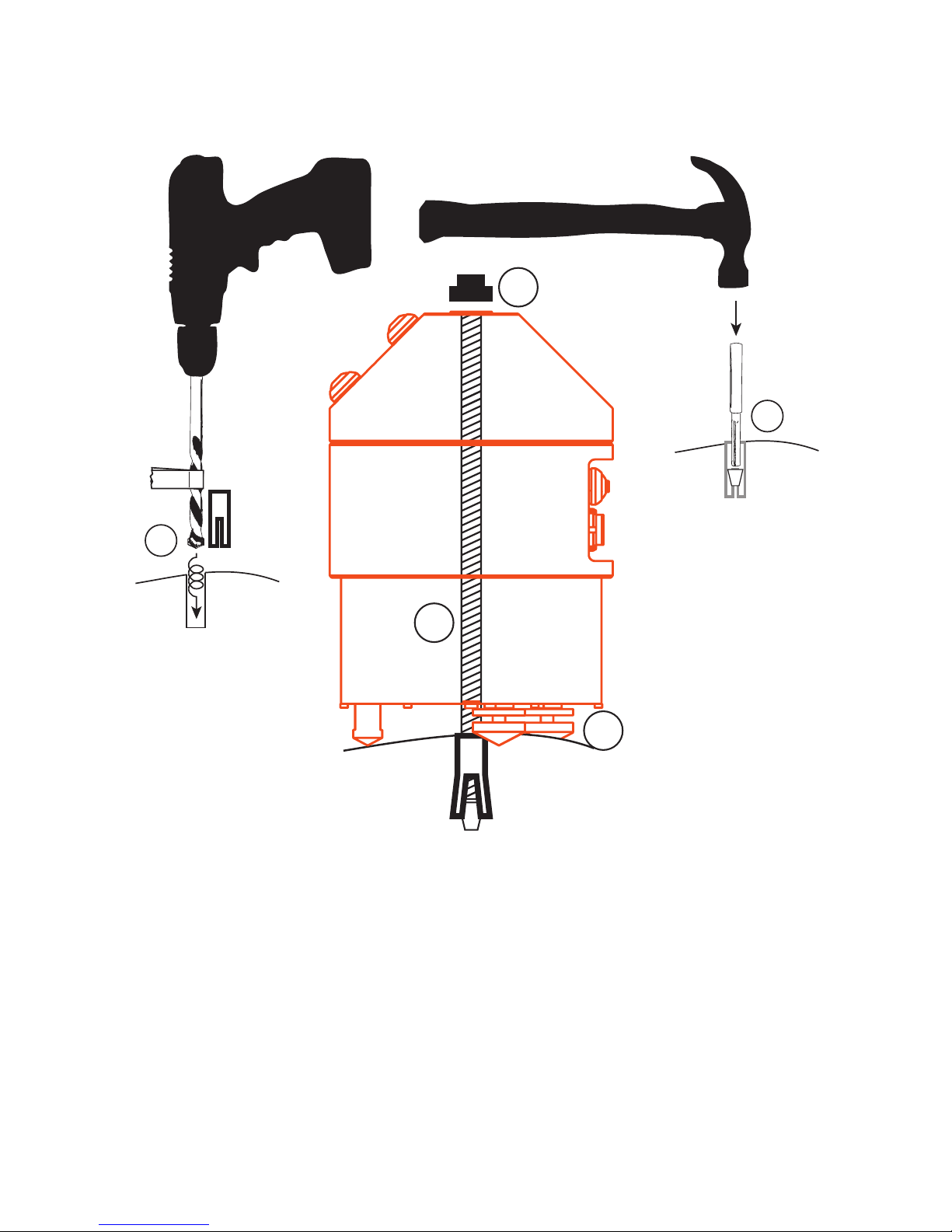
To attach the Blast or SMA to a hard surface (e.g. rock or concrete) we recommend you use
the included threaded rod, nut and anchor system through the centre of the sensor, along
with the standard feet for level adjustment. You’ll need a hammer drill, a hammer, and the
included installation kit.
1. Using the supplied 10mm masonry bit and your hammer drill, make a vertical hole for
the drop-in anchor.
Tip: measure the depth of the anchor and place some tape on the drill bit so you know how deep to drill
1
3
10
6
8

29
2. Insert anchor thread-side up into hole. Gently tap with hammer until flush with surface
3. Insert the tapered end of the anchor setting tool into the anchor.
4. By tapping down the embedded spreader, the anchor will bite into the hole. A few firm
taps of your hammer will be enough to punch the spreader to the bottom of the anchor.
5. Screw the supplied 8mm threaded rod into the anchor. After tightening, ensure the rod
cannot be pulled out of the ground by hand.
6. Using the central hole in the Gecko, slide the unit over the threaded rod.
7. Orienting your recorder depends on your application. We recommend:
a. For earthquake monitoring, rotate the Gecko until the arrow is pointing North
b. For structural monitoring, point the North arrow along an axis of your structure
8. Loosen the upper locking nuts on the adjustable feet and screw the feet in or out until
the bubble on top of the Gecko is centred indicating that the chassis is level.
9. Screw the locking nuts up to the base of the Gecko so that the feet can no longer be
adjusted.
10. Use the supplied flanged plastic nut to lock the Gecko down onto the threaded rod.
Hand tightening is sufficient to tie the Gecko down for better coupling and to avoid
accidental movement.
If you need to move your sensor, you can reuse the threaded rod and locking nut.
Additional M8 Ramset DynaSet Drop-in Anchors can be purchased at hardware stores, or
contact us if you require any spare parts.
Gains, range and clip levels
The Gecko Blast’s geophones have a nominal output of
28.8V/m/s. The Gecko recorder has an input range of ±20V at a
gain of x1, which equates to a clip level of 694.4mm/s. The
typical noise level at a quiet site is less than ±0.005mm/s, and
at a gain of x1 the Gecko Blast resolution is about 0.0001mm/s,
or about 50 times lower than a typical monitoring site, so you
should not need to change the gain. If you do increase the gain
for higher sensitivity, the clip level will be affected as estimated
in the table (left).
The Gecko SMA uses ±4V output range sensors, so to maximise the resolution of the data
the Gecko SMA will be shipped with a gain of x4, which will use 80% of the Gecko’s dynamic
range. Increasing the gain further will reduce the clip level of your SMA.
Gain
Clip Level
x1
±695 mm/s
x2
±347 mm/s
x4
±174 mm/s
x8
±89 mm/s
x16
±43 mm/s
x32
±22 mm/s
x64
±11 mm/s
x128
±5.4 mm/s
x256
±2.7 mm/s
x512
±1.4 mm/s
30
Installing the Gecko SMA-HR
You’ll need a hammer drill, a hammer, and the included installation kit.
1. Using the supplied 10mm masonry bit and your hammer drill, make a vertical hole for
the drop-in anchor.
Tip: measure the depth of the anchor and place some tape on the drill bit so you know how deep to drill
2. Insert anchor thread-side up into hole. Gently tap with hammer until flush with surface
3. Insert the tapered end of the anchor setting tool into the anchor.
4. By tapping down the embedded spreader, the anchor will bite into the hole. A few firm
taps of your hammer will be enough to punch the spreader to the bottom of the anchor.
5. Screw the supplied 8mm threaded rod into the anchor. After tightening, ensure the rod
cannot be pulled out of the ground by hand.
6. Using the central hole in the Gecko SMA-HR, slide the unit over the threaded rod.
10
6
8
1
3

31
7. Orienting your recorder depends on your application. We recommend:
a. For earthquake monitoring, rotate the Gecko until the arrow is pointing North
b. For dam monitoring, point the North arrow along the dam wall with East direction
pointing downstream
c. For building monitoring, align the arrow of the Gecko to the axis of your building
that is closest to North
8. Loosen the upper locking nuts on the two adjustable feet and screw the feet in or out
until the bubble on top of the Gecko is centred indicating that the chassis is level.
9. Screw the locking nuts up to the base of the Gecko so that the feet can no longer be
adjusted.
10. Use the supplied flanged plastic nut to lock the Gecko down onto the threaded rod.
Hand tightening is sufficient to tie the Gecko down in case the ground acceleration
exceeds the force of gravity or horizontal friction.
7b
7c
32
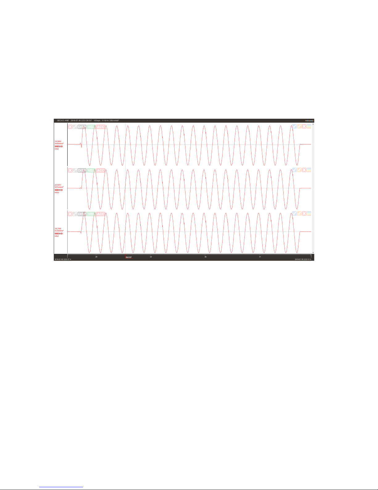
Calibrating a Gecko SMA-HR
The Gecko SMA-HR has an in-built calibration procedure whereby the processor sends a 5Hz
sine wave of 1V amplitude to excite the sensor components. By comparing the sensor
response over time you can check that your sensor is still within specification.
After running the calibration routine using the feature discussed earlier in this user manual,
open the files from your SD card’s continuous data archive that correspond to the time you
performed the calibration to see how the sensor responded. It should look like this:
Installing the Gecko Tremor
You can follow the same installation procedure as the SMA-HR for the Tremor. The main
difference is that the typical application for the Tremor will either be local earthquake
monitoring (in which case you would orient the arrow on the lid of the Gecko to point North)
or for local blast or vibration monitoring (in which case you may wish to orient the arrow to
point towards the vibration source which will make the North channel a record of radial
energy, which in turn makes the East channel a record of transverse motion.
33
Installing the Gecko Prism
The Gecko Prism contains a very robust but very sensitive velocity sensor. Once the
seismograph is powered on, be careful not to move the sensor. Pressing the buttons to
control the unit should not send the sensor into a clipping condition. If you accidentally
knock the sensor and the signal levels start clipping, simply turn the unit off for a second
and then on again to quickly settle the sensor.
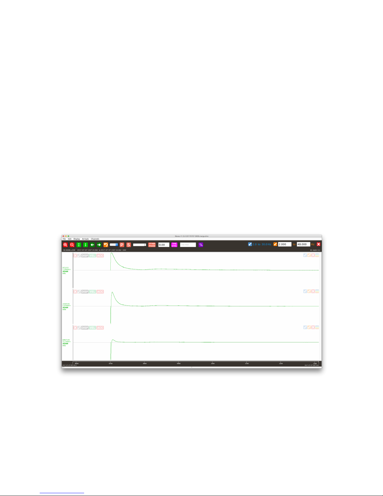
Checking Sensor Operation
After powering up your Prism, from the Home Screen it is recommended that you press the
Up button to view the signal values to check that the sensor starts up correctly.
About 20 seconds after power is applied, the Prism sensor will start up, one channel at a
time: East, North, then Up. Depending on the tilt, the signal values will shoot to a full scale
(positive or negative 8 million counts) and it will then begin to settle to the zero level. The
values may stay at the clip level for a few seconds as the sensor output has a greater range
than that of the recorder, but you’ll soon start to see the numbers heading towards a zero
signal level. It takes about an hour for the integrators to settle and get close to the zero
level, and a few hours to settle completely - see 6+ hour recording below.
If one of the channel signals appears to be jumping around randomly, or if the sensor is
making a regular clicking or buzzing sound, turn the Prism off and on again after a few
seconds to restart the sensor initialisation routine. This state may occur if you knock or
move the sensor excessively during the initialisation period.
34
Appendix B
Internal Battery
When the optional internal Nickel Metal Hydride (NiMH) battery is fitted to the Gecko
Rugged, Prism or SMA-HR, the Gecko power circuit will be set to cut power when the
battery voltage drops too low to protect the battery.
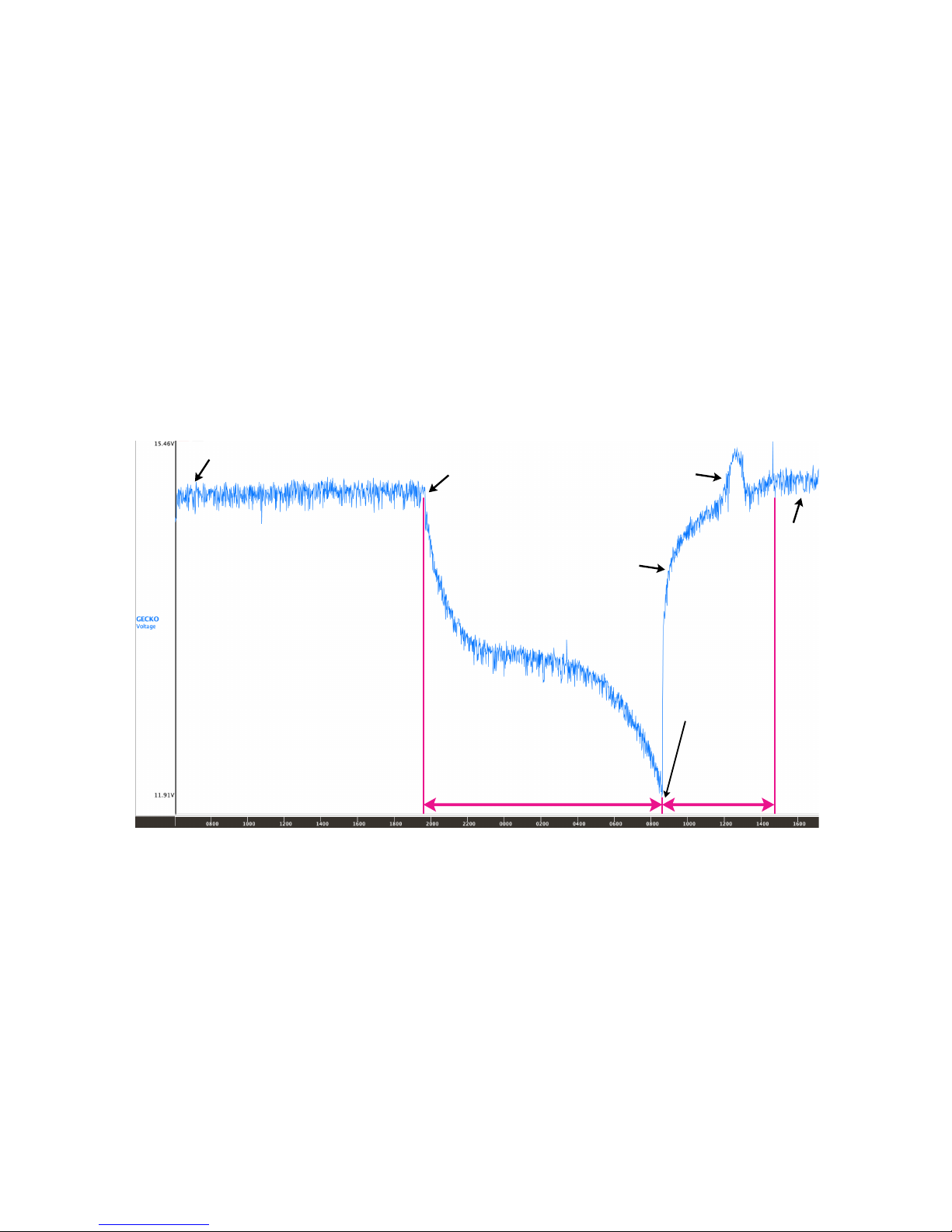
The internal battery pack is expected to run Gecko sensor models for several hours, with
backup time depending on Gecko model and the state of battery charge when AC power is
disconnected. When power is reconnected after the battery is discharged, the battery should
be fully charged in around 6 hours while the Gecko is operating, after which time the
regulator will keep a small float current flowing to the battery that will offset the power the
system draws while running.
The internal battery pack is supplied with a 12V power supply plug pack that is compatible
with 110-250V AC power sources, along with a NiMH charge regulator which is programmed
to charge to battery pack in such a way as to maximise the life of the battery. The internal
battery pack can still be charged even if the Gecko itself is switched off.
The AC plug pack outputs a DC voltage, but the charge regulator accepts power from any
type of DC power source, from 10V to 70V DC. We recommend that the power rating of
your DC supply should be at least 24W (2A @ 12V DC).
Float
Charging
AC power
disconnected
New 1650mAH
NiMH Battery
Discharge and
Recharge Test
(using Gecko SMA-HR)
Gecko
switches
off to
protect
battery.
AC power
connected
Fully charged battery gives SMA-HR
more than 12 hours backup run time
SMA-HR running.
Fully recharged in
around 6 hours
Constant
Current
Charging
Constant
Voltage
Charging
Float

35
Charge Regulator
Rechargeable Nickel Metal Hydride (NiMH) batteries require a particular power delivery cycle
for optimum charging and battery life. An unregulated power supply can provide a NiMH
battery pack with charge, but without proper regulation the battery can become damaged
from over-charging or over-heating. Please use the supplied charge regulator and AC plug
pack to maintain battery condition.
Depending on the options ordered, the charge regulator may be supplied in a small
weatherproof casing or packaged in a wall-mountable box containing other optional
components. In either case, a single LED on the charge regulator provides the status of the
charging cycle and displays any errors. Use the information below to decode the status of
the charge regulator and the battery condition.
LED Patterns (routine)
Traffic light (Red-Orange-Green) System reset. Occurs at power-on
and when battery is connected
Slow Orange blink System waiting. Battery disconnected
Solid Orange Constant current phase
Orange with Green blink Constant voltage phase
Solid Green Charge Complete. Float Charge continues
LED Patterns (exceptions)
Three Red Flashes Charge suspended. Battery voltage too low
Two Red Flashes Charge suspended. Battery voltage too high
Slow Red blink (Once every 5 sec) Charge suspended. Battery or PCB too hot
Fast Red blink Thermistor error. Needs input power reset
Orange blink (Once every 0.5 sec) Timeout
Solid Red Fault. Needs input power reset
36
Appendix C
Perle IOLAN DS1 Ethernet Adaptor
If you need to stream your seismic data over a Local Area Network (LAN) or over the
Internet in real time to a remote computer, an Ethernet adaptor is available for connection
to the recorder’s communication port. Our free Kelunji Hub and Live Stream software is
available for installation on your own remote Windows or Linux computer, or you can
subscribe to our cloud data hosting service. Email sales@src.com.au for pricing and
conditions on our cloud hosting service.
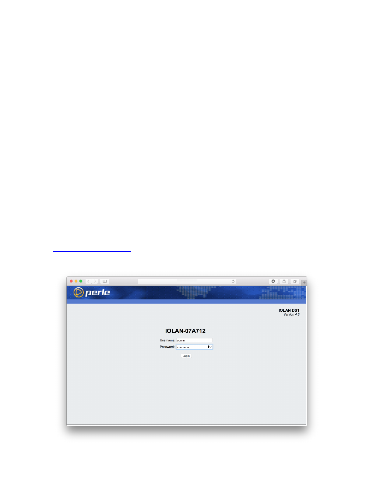
The “IOLAN DS1” Ethernet adaptor, manufactured by Perle, is a serial to Ethernet adaptor
which can be configured using a web browser connected to the Ethernet side of the device.
We have set the default IP address of the device to 192.168.20.100 with a gateway setting
of 255.255.255.0. It is unlikely that the default IP address will be allowed on your LAN, so
you will need to modify the device settings. The device is also configured to stream data to
our cloud data service, so if you have installed Kelunji Hub on a computer on your network
you will need to modify the IP address to that of the destination computer.
To change these settings, you will need to communicate with the device using a web
browser. To do this, set your computer’s IP address to 192.168.20.50, then set your
computer’s gateway address to 255.255.255.0, then open a web browser and type
http://192.168.20.100/ into the address bar. You will be asked for a username and
password to log in to the device, which are admin and superuser respectively.

37
Change IP address of the Ethernet adaptor
When you log into the Ethernet adaptor, you’ll see the screen below.
You will most likely need to
change the IP address of the
device to an address that is
compatible with your LAN.
Click on the “Network”
button on the main screen
or the “Network” folder in
the left side bar to view the
network settings.
Click on the “IP Settings”
button or icon in the side
bar folder to edit the IP
address, subnet mask, and
gateway address. You can
set the device to have a
fixed IP address or you can
set it to use DHCP to
request an automatic
address from your network.
DHCP is the most common
way computers connect to a
LAN.
If you have set the device to
use DHCP but are unsure
what IP address it has been
assigned, download the
Device Manager software
from perle.com and install it
on a Windows PC to see the
devices on your network.
Additional network settings
are available. If you are
unfamiliar with these
settings, please consult your
IT Administrator for advice.

38
Define IP address of Kelunji Hub computer
As supplied the Ethernet adaptor will try to connect to our Cloud-based Kelunji Hub data
reception system. If you have subscribed to our online hosting service you will be able to
extract data from this server’s archive using Waves.
If you have chosen to run Kelunji Hub on a computer on your local network, you’ll need to
modify the Host destination IP address that your Ethernet adaptor is trying to connect to. In
the left side bar menu, click on “Advanced” under the Network settings, as shown below.
Click on “KelunjiHub” in the
Host Table to highlight it,
then click the “Edit” button.
A small window will pop up
allowing you to edit the Host
name and address.
Warning: DO NOT change
the name of the Host
from “KelunjiHub”
Enter the IP address of the
computer that is running
your local copy of Kelunji
Hub, then click “OK”.
To apply all of the new
settings, reboot the IOLAN
device using the link at the
bottom right of the screen.
If you have enabled Telemetry via Ethernet in your Gecko, the Gecko will now connect to
the Kelunji Hub application on the Host server, then automatically start streaming data. You
can check the connection status on the Gecko Home screen by pressing the Right button
until the Connection status message is displayed.

TREMOR or PRISMSMA-HR
BLAST or SMA
GECKO COMPACT GECKO RUGGED
Gecko Seismographs and Accelerographs
src.com.au
Digitisers
To Record
Any Sensor
Portable
Vibration
Sensors
Professional
Earthquake
Sensors
 Loading...