

Page 1
Read Me Before Usage!
Manual of 1002
Page 2

Table of Contents
Chapter 1 Content Description
Section 1 On-Lap Monitor and Accessories —1
Section 2 Notices of Touch Screen Monitor —2
Section 3 Safety Precautions —3
Section 4 Safety Instructions —3
Section 5 Product Maintenance —3
Section 6 LCD Pixel Statement —4
Section 7 Disposal of Electronic Equipment —4
Chapter 2 Installation Instructions
Section 1 Protective Cover and VESA 100 Stand Assembly
Section 2 Connect the Video Cable and USB Touch Output and
Power Cable
Section 3 Connect the 5V 2A Charger (Optional) —8
Chapter 3 Power On and Off the On-Lap Monitor
Section 1 Power On and Off the On-Lap Monitor —8
Section 2 Monitor Display Setting —8
Section 3 Windows 7/8 Touchscreen Setting —9
Section 4 Windows 8 Touch Gesture Description —10
Chapter 4 Hot Keys, LED lights and OSD Instructions
Section 1 Hot Keys & LED lights Description —10
Section 2 OSD Description —11
Section 3 Low Power Protection Warning —14
Chapter 5 Specification
Section 1 Plug and Play —14
Section 2 Pin Assignment and Standard Default Modes —14
Section 3 Specification —15
Section 4 Troubleshooting —16
—1
—4
—4
—6
—8
—10
—14
Page 3
Chapter 1 Content Description
Section 1 On-Lap Monitor and Accessories
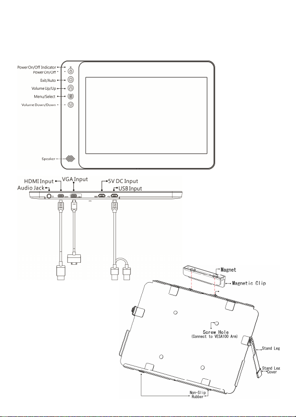
1. Parts Description
1
Fig.: 1002 buttons
and LED light
Description
Fig.: On-Lap 1002 input/
output ports
Fig.: Parts Description of
Protective Cover
Page 4
2
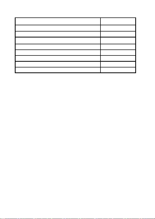
2. Package & Accessories
Accessories On Lap 1002
Protective Cover 1 pcs; Magnetic Clip 1pcs Yes
Micro USB to USB Touch Power Cable 1 pcs Yes
Micro HDMI Video Cable 1pcs Yes
VGA Video Cable 1 pcs No (Optional)
Charger (5V,Max.2A) x1 No (Optional)
Stand 4 x1 No (Optional)
(Screw + Nut)* 4 sets; Screw * 2 pcs Yes
User Manual x1 Yes
Section 2 Notice of On-Lap Monitor
1. Please do not use sharp objects to touch the screen. Gently use the finger
to touch or swipe on the screen.
2. Please do not place touch monitor near light bulb, electrical wire or
other items that generate electromagnetic field, which will result in abnormality to touch function.
3. Please do not press the arm or other item to the screen or apply heavy
pressure onto the screen.
4. Please keep fingers clean and dry when performing touch. If the finger
has water drops it may result in the touch screen unable to determine
touch location. Use finger to touch the screen, do not use fingertip to
perform touch.
5. Touch signal needs to communicate through USB cable to Windows 8 or
Windows 7 installed computer. Need to first make sure the Micro USB to
USB Touch Power Cable is inserted into the correct port in order to have
touch function capability.
6. Unstable power input will interfere with touch signal, resulting in inaccurate or failed touch function. It is suggested to use the USB port on laptop or manufacturer’s 5V 2A Charger.
7. Disconnect power source before cleaning. Please use soft cloth to clean
touch screen monitor. When difficult to clean, wet the cloth then perform cleaning again. Please do not use chlorine, alcohol, ammonia, detergent or other corroding solvents. These solvents may cause damage
to the touch screen monitor or leave unremovable residue.
Page 5

8. Avoid LCD monitor become exposed to direct sunlight for a long period
of time, which may result in damage. When monitor displays different
images, image brightness may become slightly uneven. Showing the
same image for a prolonged period of time may result in poor liquid
crystal response time, causing image persistence to occur.
9. Monitor may be broken when heavy pressure or sharp object is applied
to it. Please properly cover the monitor and make sure the monitor glass
will not be pressed if need to carry it outdoors. Placing touch screen
monitor inside carrying bag may result in monitor glass damaged by
pressing, dropping or colliding with laptop and other items. Place the
monitor in protective cover, and carefully make sure the screen glass will
not be pressed or touched.
Section 3 Safety Precautions
1. The Product may be severely damaged from overturning or falling.
Please do not place on a shaky or unstable table, cupboard or trolley. Do
not use the On-Lap Monitor on a moving vehicle.
2. Do not place the items on a vibrating surface, vibration may cause damage to the internal components.
3. The product is not waterproof. Do not use the Product at or near a place
with water.
4. Do not insert any object into the Product’s slots or gaps.
5. Loudness warning! Avoid volume levels that may be harmful to your
hearing. Please check the volume setting before you use the Audio Jack.
Section 4 Safety Instructions
Please read this Manual carefully and observe the operation instructions and
precautionary notes. Do retain this document for future reference.
Section 5 Product Maintenance
Do not attempt to repair the Product yourself. Should any of the following
conditions occur, please contact our maintenance personnel for service:
1) Unable to operate the Product after following the instructions in the
Manual.
2) The Product falls and the outer casing is damaged.
3) Power cable or video cables is damaged.
4) Liquid infiltrated into the Product.
Any normal wear and misuse, including but not limited to product failure due to normal
usage, is not covered under warranty. Accident, damage, software or hardware changes,
force majeure, or become in contact with liquid that result in product malfunction is not
covered under warranty.
3
Page 6
4
Section 6 LCD Pixel Statement
The On-Lap Monitor uses a high quality LCD panel. Nevertheless, there might
be instances where defective pixels may occur; however, this will not affect
the normal functioning of the Product.
Section 7 Disposal of Electronic Equipment
The electronic equipment and batteries should not be disposed of with household waste but should be left at an appropriate collection point for recycling.
Chapter 2 Installation Instructions
Section 1 Protective Cover and VESA 100 Stand Assembly
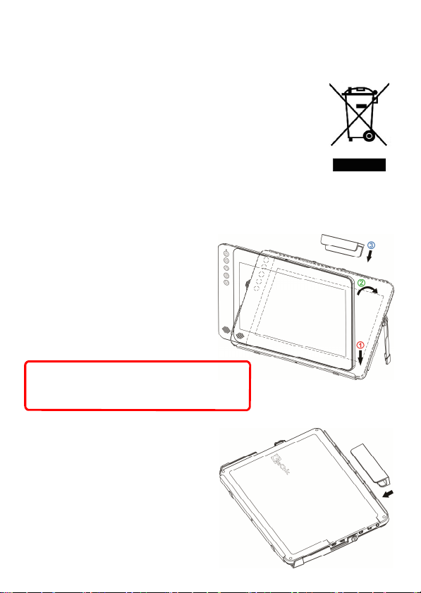
1 Install Protective Cover
1-1 Open the Protective Cover Stand,
place the monitor into the Protective Cover, place the magnetic clip
on top (Place the short side of the
Magnetic Clip on the top).
Fig : Protective Cover as screen stand
Caution: The Magnetic Clip must be placed
on the top in order to prevent the Monitor
from falling out.
1-2 Close the Protective Cover Stand,
place monitor in protective cover,
with the back facing out, place the
magnetic clip on top (Place the long
side of the Magnetic Clip on the
top)
Fig : Monitor placed in Protective Cover
Page 7
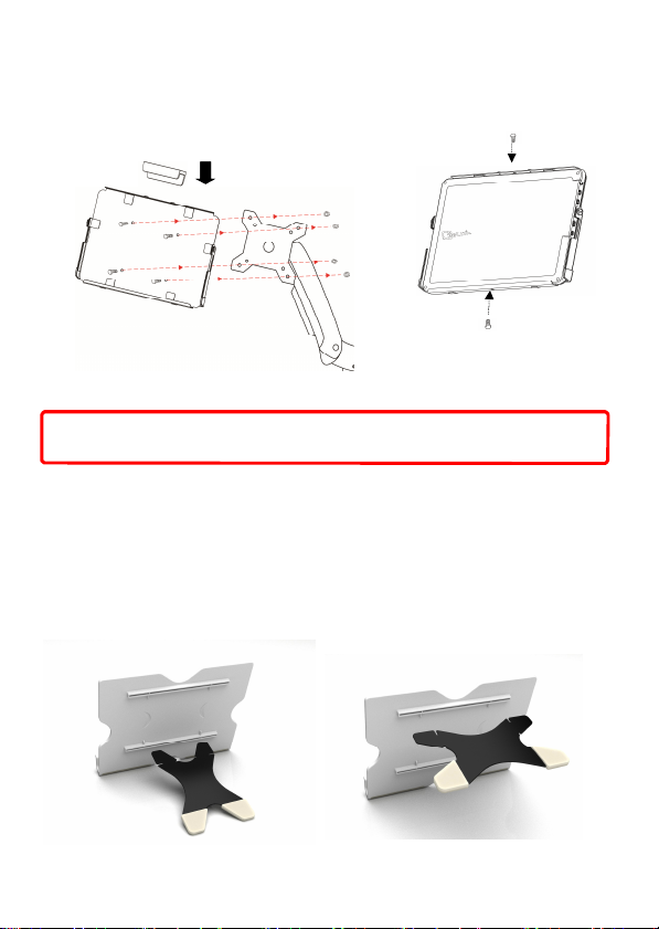
2 VESA 100 Arm Installation
Place the protective cover onto VESA 100 arm, as shown in Fig. Place the
monitor into the protective cover, place the magnetic clip on top ( short
side on the top)
5
Fig : Place the Protective Cover onto
VESA 100 arm and use Magnetic Clip
Caution: The Magnetic Clip or screws must be placed in order to prevent the
Monitor from falling out.
3 Install Stand 4 (optional)
Place Protective Cover onto VESA 100 arm, based from Fig., place the monitor
into the Protective Cover, place the magnetic clip on top
Step 1 Assemble Stand 4
Select the desired angle placement to assemble Stand 4. Before assembly,
check if X plate is properly inserted onto slot.
Fig : Install Stand 4
Fig : Screw in to secure the
Monitor
Page 8
6
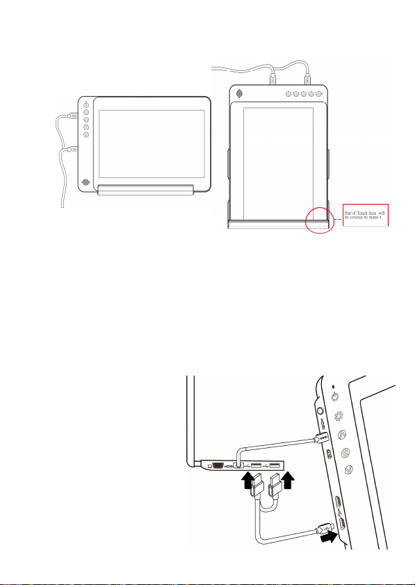
Step2: Place On-Lap monitor onto Stand 4
Place On-Lap monitor onto Stand 4. Stand 4 is positioned at the bottom center of monitor.
Fig : Place On-Lap 1002 onto Stand 4
(Remark: Place On-Lap 1002 vertically onto Stand 4. Touch screen will be
covered by Stand 4, may affect some Windows 8 touch gestures. Stand 4 is
not recommended for Windows 8 user who needs to place the monitor
vertically.
Section 2 Connect the Video Cable and USB Touch Output and
Power Cable
Step1: Connect USB Touch Output and Power Cable
Connect USB Touch Output and Power Cable’s Micro USB (B type) con-
nector to On-Lap 1002’s Micro
USB port. Connect the other end,
USB connector to USB port of
laptop. With this connection,
laptop will provide power and
touch signal to On-Lap 1002.
If one USB port on laptop is
unable to provide enough power,
please connect the two USB
connectors to two USB ports on
laptop, this can provide twice the
power.
Fig.: Connect USB Touch Power Cable
Notebook
On-Lap 1002
Page 9
*On-Lap 1002 has two Micro USB ports:
USB port can transmit touch signal and power, DC IN port can only transmit
power. If USB Touch Output and Power Cable connect to DC IN port, touch function
cannot be used.
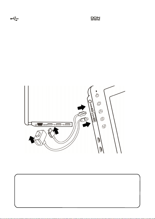
Step2: Connect the Video Cables
Choose or based on the type of connection port
Connect Micro HDMI Video Cable’s Micro HDMI (-D) type connector to
Micro HDMI port of On-Lap 1002. Connect the other end, HDMI-A type connector to laptop, tablet, game console, or DVD player’s HDMI port.
Or connect VGA Video Cable’s VGA connector to VGA port of On-Lap
1002. Connect the other end, D-Sub connector to D-Sub/VGA connector port
on the laptop. (Need to purchase VGA Video Cable designed for On-Lap 1002
in order to use)
Notebook
On-Lap 1002
7
Fig.: Connect Micro HDMI or VGA Video Cable
*The two On-Lap 1002 video cables look similar in appearance, match with the
diagram before connecting to avoid connecting to the wrong port. If wrongly
connect Micro HDMI Video Cable to VGA port, or wrongly connect VGA Video
Cable to HDMI port, the monitor will not display.
**Only when Micro HDMI Video Cable is connected will the monitor have
sound. VGA Video Cable is not able to transmit audio signal .
Page 10
8
Section 3 Connect the 5V 2A Charger (Optional)
If wish to have On-Lap 1002 use independent
power source, use 5V 2A Charger to provide
5V DC and not use power from laptop, please
refer to diagram. Connect 5V 2A Charger to
Micro USB port (DC IN) of On-Lap 1002. At this
time, On-Lap 1002 will only use power from
DC IN port.
*Do not disconnect the USB Touch Output and
Power Cable from On-Lap 1002 USB port, or else
touch function cannot be used.
Chapter 3 Power On and Off the On-Lap Monitor
Section 1 Power On and Off the On-Lap
1. From Off state to On state: Press Power Button to activate On/Off.
2. First time use: When Micro USB to USB touch signal and power connect
to USB port on computer or 5V DC Charger, On-Lap will automatically
start and detect video signal to automatically display video. (Connection
method can refer to Chapter 2 Section 2)
Section 2 Monitor Display Setting
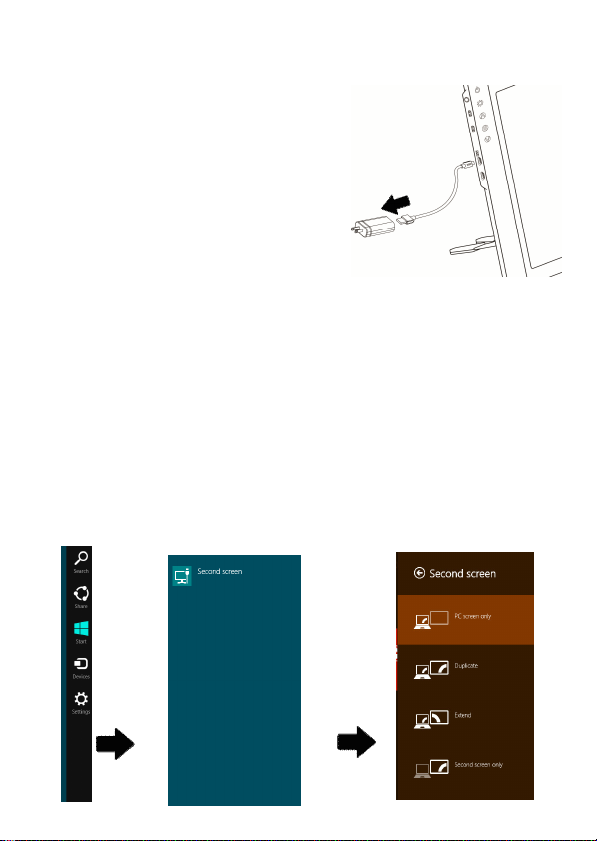
1. Set Extended Display Mode – Windows 8 /8.1
Select directly from right side of screen [Devices] ->select [2nd Monitor] ->
select [Extend Mode]
For screen resolution setting please refer to 2
Page 11
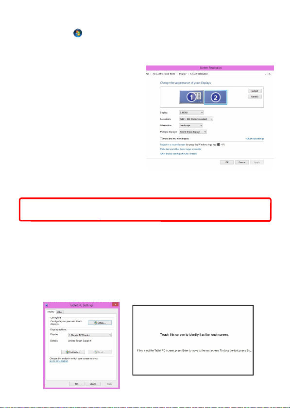
2. Resolution setting – Windows 7 system
● Click on icon
● Click on Control Panel > Appearance and Personalization
● Click on Display > Connect to an external display.
Normally Display ① is the laptop’s monitor, Display ② is the external
monitor. Click on Detect if you are
unsure.
● At Display, select “2.HDMI”
(digital video) or “2. display
device: VGA” (analog video)
for Display
● Select “1280x1080” for
Resolution
● Select "Landscape" or
"Portrait" for Orientation.
● Select "Extend these displays"
for Multiple display, and drag
Display 2 to the right side of Display 1. For Duplicated mode, select
"Duplicate these displays".
● Select OK and exit after saving the settings.
Caution: Resolution of On Lap 1002 must be set as 1280x800 (full screen),
otherwise the touch function can not be operated correctly.
Section 3 Windows 7/8 Touchscreen Setting
If the computer is unable to automatically start touchscreen function, please
use the “Tablet PC Setting ”of the Windows 7/8 Control Panel to perform
touchscreen setting.
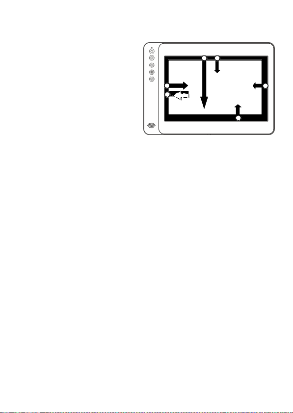
As below Fig., please select “Setting (S)”, when Windows message appears
on the screen of On-Lap 1002, follow the direction to touch the screen and
the setting is complete.
9
Page 12
10
Section 4 Windows 8 Touch Gesture Description
Common Touch Gesture Introduction:
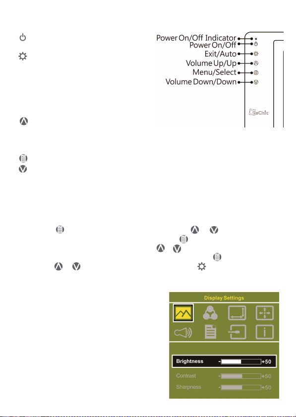
1. Use finger to swipe in from
edge:
Swipe in from the right edge
of the screen (Arrow 1) : Open
the five charms – Search, Share,
Start, Devices, and Settings
Swipe in from the left edge of
the screen (Arrow 2) : Switch
between apps
Swipe in from the left edge of
the screen then out toward the left edge of the screen (Arrow 3): Display
all apps
Swipe in from the top edge (Arrow 4) or bottom edge (Arrow 5):
Display commands of app, like Add New, Reminder, etc.
With touch, drag the app from the top edge of screen (Arrow 6) to the
bottom of the screen: Close app
2. Select item: Tap on the item to open. This function is similar to clicking
on mouse.
3. Press and hold the item for a few seconds then release: Display item
information. This function is similar to right-clicking on mouse.
4. Zoom in and out: Touch the item with two fingers then move fingers
toward each other (pinch) or away from each other (stretch).
5. Slide finger on the screen, horizontally or vertically, to move through
content. This function is similar to scrolling with a mouse.
Chapter 4 Hot Keys and OSD Instructions
Section 1 Hot Keys and LED Light Description
* The buttons are capacitive touch module. Please touch the buttons by the fingertip
gently. Do not press the buttons with stress or continuously, which may cause them fail
to response. “Increase/up” or “Decrease/down” continuously shall be done by
touching the button and holding. Do not touch two buttons at the same time, due it may
cause no response or fault response.
LED Lights Description :
It shows green light when turn on On-Lap Monitor and shows red light when
shut down.
Page 13
11
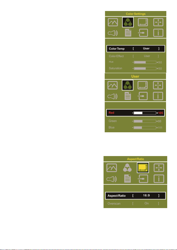
Hot Keys Description
Power: Touch the Power Button can
power on/off the Monitor.
Exit/Auto Adjustment: In the OSD
panel, touch the Exit Button to exit and
back to the previous page. When there is
no OSD menu, touch this
Button will activate automatic adjustment function (only pertains to analog
VGA signal)
Increase Volume/UP: Touch this
Button to increase the volume of speakers. If the OSD menu is launched, touch this button will move up or move left
the list. Touch and hold for automatic continuous increase.
Menu/Select: Touch the Menu Button to launch OSD panel.
Decrease Volume/Down: Touch this Button to decrease the volume of
speakers. If the OSD menu is launched, touch this button will move down or
move right the list. Touch and hold for automatic continuous decrease.
Section 2 OSD Description
1. Basic Button Operation
Press button to launch the OSD panel. Press or to view the
functions. To adjust a certain function, press to launch it. If the selected
function consists of sub-menu, press or again to view the submenu. When the desired function is highlighted, press to launch it.
Press or to change the setting. To exit, press to exit. Repeat the
preceding steps to adjust other setting.
2. Display Settings
As shown in Fig., after Display Settings
is launched, can adjust Brightness,
Contrast, and Sharpness.
Page 14
12
3. Color Setting
As shown in Fig., after Color Settings is
launched, can adjust Color Temp and
Color Effect to adjust screen color setting.
Hue setting can make the image color
lean toward green or purple
Saturation setting can make saturation
more vivid or more black and white
At Color Temperature, select “User”, can
adjust RGB color setting, please refer to Fig.
Select “Cool” can increase the blue saturation of the image. Select “Warm”can increase the red saturation of the image. At
Color Effect, select “Standard”, “Game”,
“Movie”, “Photo” and “Vivid
Select “Standard” can adjust the Hue and
Saturation of Red/Blue/Green/Cyan/Yellow/
Magenta
4. Aspect Ratio
Please refer to Fig. Suggested setting is 16:9. When HDMI image is 4:3
format, can select 4:3, make image not enlarge to 16:9 and change shape.
Using VGA image input won’t have this
function
Notice: When use 4:3 setting, the left and
right sides of On-Lap 1002 will show
black frame. Because its not full screen
image display, thus image location and
touch signal location will not be the same,
will not be able to touch the correct loca-
tion
Overscan: Only when input HDMI Video
signal (ex. 1080P/720P/576P/480P) , can
use such function. Use this function can adjust the image scan area.
Page 15
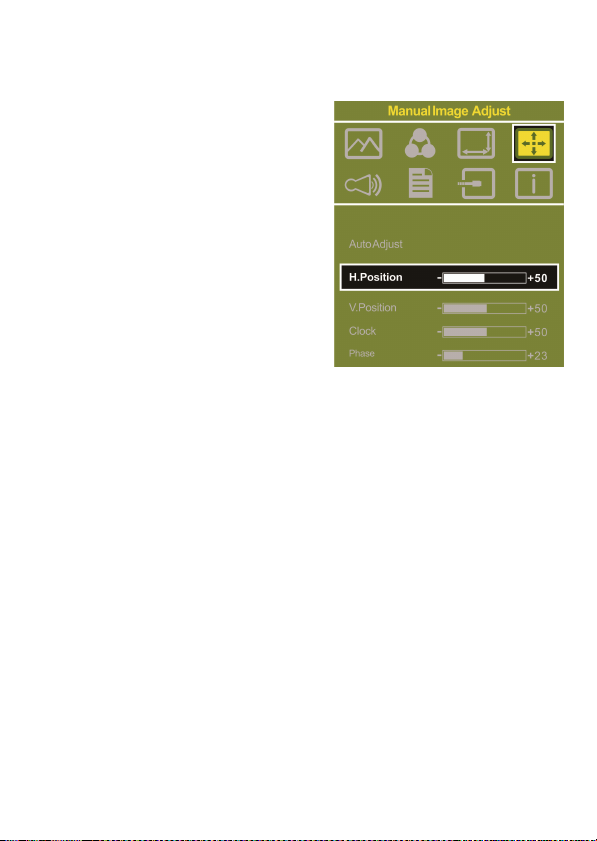
5. Manual Image Adjust
Auto Adjust: Only when input VGA signal can use such function. Will auto-
matically adjust VGA setting
H.Position: Moves the display area left
and right .
V.Position: Moves the display area up
and down
Clock: Adjust the pixel clock for user's
preference
Phase: Adjust the pixel phase for user's
preference
6. Audio: Adjust volume or select mute
7. OSD Menu
OSD Timer: Adjust OSD Time
OSD H. POS: Moves OSD left and right
OSD V. POS: Moves OSD up and down
OSD Transparency: Makes OSD transparent
Language: Select OSD language
Reset: Restore to factory setting
8. Input Source: Select VGA signal source, HDMI signal or Auto Detect
9. Information: Display factory version
13
Page 16
14
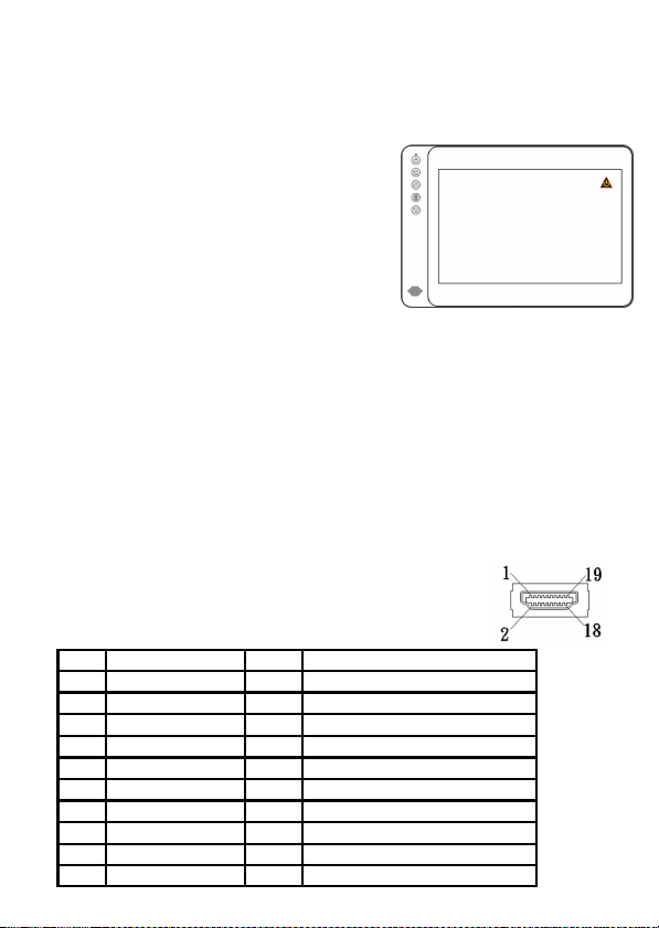
Section 3 Low Power Protection Warning
If the volume setting is too high, the power requirement may be greater than
the power provided by computer or external 5V
DC Charger. At this time, the Low Power Protection Warning will appear. Please reduce the
volume immediately. Connect the two USB
connectors of Micro USB Touch Output and
Power Cable to the two USB ports on computer.
If the volume is not reduced in time, the Monitor
will decrease the volume and brightness automatically.
Fig.: Low voltage warning shown at upper right corner on screen.
Chapter 5 Specification
Section 1 Plug and Play
The On-Lap Monitor conforms to VESA DDC standard and supports VESA
DDC2. DDC2B is a bi-directional data channel based on I2C protocol. The host
can request EDID information over the DDC2B channel. The On-Lap Monitor is
able to inform the host system of its identity, and depending on the level of
DDC used, communicate additional information about its display capabilities.
Section 2 Pin Assignment
1. HDMI Connector Pinout
Pin Name Pin Name
1
TMDS Data2+
2
TMDS Data2 Shield
3
TMDS Data2 –
4
TMDS Data1+
5
TMDS Data1 Shield
6
TMDS Data1 –
7
TMDS Data0+
8
TMDS Data0 Shield
9
TMDS Data0 –
10
TMDS Clock+
Fig.: HDMI-A Connector
(Connect to HDMI port)
11
12
13
14
15
16
17
18
19
TMDS Clock Shield
TMDS Clock –
CEC
Reserved
SCL (I²C Serial Clock for DDC)
SDA (I²C Serial Data Line for DDC)
DDC/CEC Ground
+5 V Power
Hot Plug Detect
Page 17
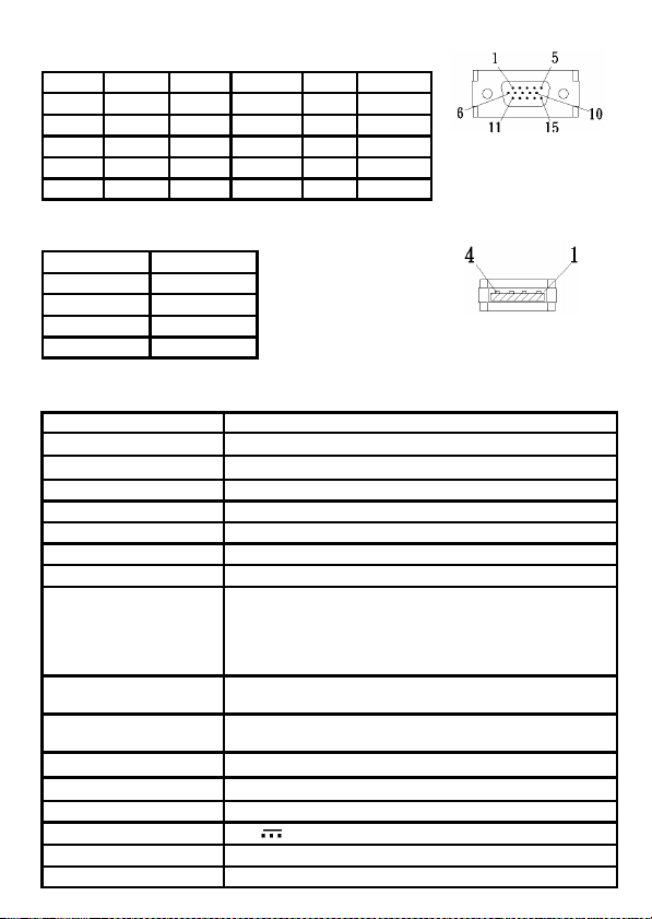
2. VGA Connector Pinout
Pin No. Name Pin No. Name Pin No. Name
1 RED 6 RGND 11 NC
2 GREEN 7 GGND 12 SDA
3 BLUE 8 BGND 13 HSYNC
4 NC 9 +5V 14 VSYNC
5 GND 10 SGND 15 SCL
Fig.: VGA connector
(connect to PC’s
VGA port)
3. USB Connector Pinout
Pin No. Name
1 Vcc (+5V)
2 D+
3 D-
4 Ground
Fig .: USB Connector
Section 3 Specification
1002
Panel Type 10.1” IPS LCD 16:10 WIDE (LED Backlight)
Resolution / Color Depth 1280 x 800 /262K colors
Pixel Pitch 0.1695mm
Viewing Angle 85°/85°/85°/85°
Contrast Ratio 800:1
Response Time 25 (ms)
Brightness 250 (cd/m2)
Resolution Supported
Support Video Mode
Touch Type
Support OS
Touch Hardness Hardness of Touch Glass ≧7H
Speaker 1x 1.0W(Max.) (Rated Impedance 4 Ω at 2KHz)
Rating Votage 5V DC
Rating Power 1.2A
Waiting Power 90mA
1920x1080(60Hz); 1440x900(60Hz); 1366x768(60Hz);
1280x1024(60Hz); 1280x800(60Hz); 1280x768(60Hz);
1024x768(60Hz); 800x600(60Hz) (Caution: If video output
frequency of computer graphic card is out of the above
range, it may cause the panel damage.)
1080P(60Hz); 1080i(30Hz); 720P(60Hz); 480P(60Hz) ; 480i
(60Hz)
Projective Capacitive Touch Monitor, support 10-finger
multi-point touch.
Support Microsoft Win8.1、Win8、Win7
15
Page 18
16
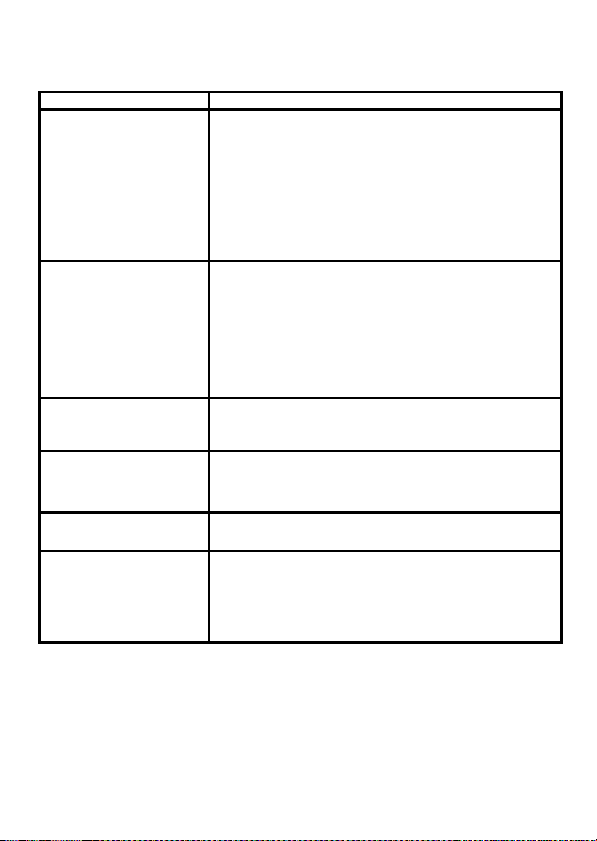
Section 4 Trouble Shooting
1. Image or Audio output troubles
Problem Solution
1. Check if Micro USB Touch Output and Power Cable is
properly connected between the computer and On-Lap
1002’s USB port. Turn down the monitor and unplug
No response when finger
touches on monitor
No image
OSD displays “ No
Signal” warning
Image disappears, or image
size is too big, too small, or
image is not centered.
Monitor has image but no
sound
Monitor displays Low
Power Protection Warning
the cable. Plug the cable and turn on the monitor again.
2. Check if Micro USB Touch Output and Power Cable is
mistakenly connected to DC IN port. If so, only power is
transmitted and no touch is available.
3. Refer to Charter 3 Section 3, do Windows 7/8
touchscreen setting
1. Check if Power On/Off Indicator shows green light. If
not, it means no power connection. Please refer to user
manual instruction to connect power.
2. Check if VGA/HDMI Video Cable is connected between
On-Lap’s connector port and computer’s connector
port.
3. Check if Micro HDMI Video Cable connector is accidently connected to the VGA port on On-Lap.
Please check if the Video Cable is correctly connected to On-
Lap Monitor’s video input port and laptops’ video output
port.
The trouble may be caused by VGA video input. Please
adjust resolution, clock, horizontal position and vertical
position via OSD.
1. Press UP Button to increase audio level.
2. Use of VGA input will not have audio signal.
Because the output current is greater than the input current,
please lower the audio and brightness level. Connect the two
USB connectors of Micro USB Touch Output and Power Cable
to the two USB ports on the computer to increase power. Or
using 5V 2A Charger to supply power.
2. The unavailability of “ Duplicate these displays” or “ Extend these
displays” in Display setting may be limited by the graphics chip of the
laptop or have the graphic chip features limited due to the power saving
mode of the laptop or have the graphic chip driver updated. Please consult your laptop manufacturer or graphic chip manufacturer.
Page 19

GeChic Corporation
5F-3, No. 138, Zhongming S. Rd.,
West Dist., Taichung, Taiwan (R.O.C.)
Customer Service: [email protected]
www.gechic.com
 Loading...